EP4027313B1 - Light-signaling device for access points - Google Patents
Light-signaling device for access points Download PDFInfo
- Publication number
- EP4027313B1 EP4027313B1 EP21150472.5A EP21150472A EP4027313B1 EP 4027313 B1 EP4027313 B1 EP 4027313B1 EP 21150472 A EP21150472 A EP 21150472A EP 4027313 B1 EP4027313 B1 EP 4027313B1
- Authority
- EP
- European Patent Office
- Prior art keywords
- light
- control unit
- automation
- lighting element
- communication
- Prior art date
- Legal status (The legal status is an assumption and is not a legal conclusion. Google has not performed a legal analysis and makes no representation as to the accuracy of the status listed.)
- Revoked
Links
Images

Classifications
-
- G—PHYSICS
- G08—SIGNALLING
- G08B—SIGNALLING SYSTEMS, e.g. PERSONAL CALLING SYSTEMS; ORDER TELEGRAPHS; ALARM SYSTEMS
- G08B5/00—Visible signalling systems, e.g. visible personal calling systems or remote indication of seats occupied
- G08B5/22—Visible signalling systems, e.g. visible personal calling systems or remote indication of seats occupied using electric transmission; using electromagnetic transmission
- G08B5/36—Visible signalling systems, e.g. visible personal calling systems or remote indication of seats occupied using electric transmission; using electromagnetic transmission using visible light sources
- G08B5/38—Visible signalling systems, e.g. visible personal calling systems or remote indication of seats occupied using electric transmission; using electromagnetic transmission using visible light sources using flashing light
-
- G—PHYSICS
- G08—SIGNALLING
- G08B—SIGNALLING SYSTEMS, e.g. PERSONAL CALLING SYSTEMS; ORDER TELEGRAPHS; ALARM SYSTEMS
- G08B5/00—Visible signalling systems, e.g. visible personal calling systems or remote indication of seats occupied
- G08B5/22—Visible signalling systems, e.g. visible personal calling systems or remote indication of seats occupied using electric transmission; using electromagnetic transmission
- G08B5/36—Visible signalling systems, e.g. visible personal calling systems or remote indication of seats occupied using electric transmission; using electromagnetic transmission using visible light sources
Definitions
- the invention relates to the field of the automation of doors, gates, and similar barrier devices conventionally employed to close access points, for example to garages or, more generally, to delimited areas.
- Such devices are also sold and currently installed by the Applicant.
- An example is the component belonging to the series called KIARO in the current sales catalog available on the Internet.
- these devices are limited to providing an indication of movement in a non-differentiated manner. For example, they do not indicate whether the barrier is opening or closing or when it is sufficiently open to allow going through the access point.
- Document DE202011103660U1 discloses an example of a signaling device and an associated control device for signaling the departure time of public transport, in particular rail vehicles, and a means of transport with such a signaling device.
- the invention achieves the object with a light-signaling device according to claim 1.
- the lighting element may advantageously comprise a plurality of light sources, for example RGB LEDs arranged on a support having any shape, e.g. circular, which can be controlled by the control unit individually or in blocks to create light patterns which encode information on the status of the automation with which the signaling device is associated or associable, or simple lighting or guiding functionalities.
- a plurality of light sources for example RGB LEDs arranged on a support having any shape, e.g. circular, which can be controlled by the control unit individually or in blocks to create light patterns which encode information on the status of the automation with which the signaling device is associated or associable, or simple lighting or guiding functionalities.
- the light signaling may exploited to provide indications on the status of the automation, such as: in opening, in closing, automation awaiting maintenance and the like.
- the control unit may for example be programed to set the lighting element so as to emit a flashing light with a frequency which encodes a type of malfunction or anomaly. This is particularly advantageous when maintenance is provided because a device, such as a smartphone or a tablet, is sufficient to interpret the malfunction message on the basis of a reading of the light signal performed with the camera and a table for transcoding the messages.
- the signaling device may advantageously be used as hub for other devices, given that it is provided with a communication port and comprises an antenna mounted on the support and interface electronics towards said antenna.
- the interface may advantageously be in communication with the control unit to exchange data via the communication port so as to obtain a wireless communication gateway module.
- a presence detector such as a passive infrared sensor PIR, is an example of another device which may be connected to the signaling device.
- the invention relates to a system for controlling the movement of a movable access point such as a gate, a barrier, a door and the like, the system comprising:
- the central unit may advantageously be programed to send commands corresponding to system statuses to the signaling device so that the signaling device may accordingly emit a light with a light pattern, color and/or frequency which encodes the system status in the form of light message to send to a user.
- the signaling device control unit may be, for example programed to set the lighting element so as to emit a light of a first color, e.g. red, when the central unit controls the closing automation, of a second color, e.g. green, when the central unit controls the opening automation.
- a first color e.g. red
- a second color e.g. green
- the central control unit may receive commands from various sources: such as, for example Command input (terminals), BUS communication port, Radio. After receiving the commands, the central control unit acts on the motor control device and may send commands to the signaling device control unit via the BUS communication port.
- commands such as, for example Command input (terminals), BUS communication port, Radio.
- the central control unit acts on the motor control device and may send commands to the signaling device control unit via the BUS communication port.
- control commands may be sent in the form of a single message or of various messages both to the motor control device of the automation and to the lighting device, via said communication system.
- the signaling device control unit may be programed to set the lighting element so as to emit a flashing light during the opening or the closing of the automation.
- the communication system may advantageously be a bus communication system with a master/slave type protocol, with the central unit being the master, the motor control device (in those configurations not providing for the motor control device to be integrated in the central control unit) and the signaling device being corresponding slaves which receive commands from, and send statuses to, said master.
- the signaling device may comprise one or more interfaces so as to form a hub for connecting with other devices which communicate with the central unit via the control unit and the communication bus.
- One of said other devices may be an antenna and the corresponding control electronics so as to associate the signaling device with a wireless gateway functionality.
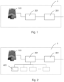
- the signaling device 1 comprises a lighting element 101 mounted on a support, a communication port 301 for receiving an ON/OFF command of the lighting element 101, and a control unit 201 in communication with the communication port 301 and the lighting element 101.
- the lighting element 101 may advantageously comprise a plurality of light sources, for example RGB LEDs arranged on a support having any shape, e.g. circular as in the drawing, which can be controlled by the control unit 201 individually or in blocks to create light patterns of the most varied types in terms of shape, color, intensity, flashing frequency, according to commands which can be set from the outside via the communication port 301.
- a plurality of light sources for example RGB LEDs arranged on a support having any shape, e.g. circular as in the drawing, which can be controlled by the control unit 201 individually or in blocks to create light patterns of the most varied types in terms of shape, color, intensity, flashing frequency, according to commands which can be set from the outside via the communication port 301.
- light signaling may exploited to provide indications on the status of the automation movement system.
- light codes may be set, which signal: opening automation, closing automation, operating anomaly, malfunction, automation awaiting maintenance, time prior to scheduled maintenance and other similar operating statuses.
- An example may be a streetlight configuration in which different colors are used according to the status of the automation of the access point with which the device is associated (opening, closing, forbidden passageway, free passageway).
- the color red may, for example identify a circumstance of forbidden passageway, green a circumstance of free passageway, while a flashing red color could be employed to identify an opening automation, while a flashing red color could indicate a closing automation.
- any type, color tone and flashing may be employed to signal the status of the automation with which the device is associated.
- the commands to the communication port 301 may be sent manually or via remote interfaces.
- such commands are sent by the same central unit which monitors the operation of the automation system, in particular by taking advantage of said communication bus between central unit and system actuation/sensor devices.
- Figure 3 shows an example of a system for controlling the movement of a movable access point, such as a gate, a barrier, a door and the like, in which the signaling device according to the invention may be used.
- the system comprises a bus system 4 to which a movement module 2 for opening/closing the automation, a central control module 3 and a signaling device 1 according to the invention, are connected.
- the modules 2 and 3 may obviously also co-exist in a same device.
- the movement module 2 comprises a motor 102, a motor control device 202, and a port 302 for receiving a barrier movement command via bus 4.
- the central control module 3 comprises a central unit 103, an input 203, and an interface port 303 towards bus 4.
- the central unit 103 is configured to read movement commands of the automation from input 203 and/or from bus 4, and accordingly to send actuation signals to the motor control device 202 via bus 4.
- the light-signaling device 1 is also interfaced with the central unit 103 via the bus communication system 4 so that the central unit 103 may send commands also to the signaling device 1, in particular to the control unit 201 thereof, via the communication port 301.
- the central unit 103 may advantageously be programed to send commands to the signaling device 1 corresponding to system statuses so that the signaling device 1 may accordingly emit a light with a light pattern, color and/or frequency which encodes the system status in the form of light message to send to a user.
- the control unit 201 of the signaling device 1 may be, for example programed to set the lighting element 101 so as to emit a light of a first color, e.g. red, when the central unit controls the closing automation, of a second color, e.g. green, when the central unit controls the opening automation.
- the drive commands may be sent in the form of a single message or of various messages both to the control device 202 of motor 102 of the automation and to the lighting device 1, via said communication system 4.
- control unit 201 of the signaling device 1 may be programed to set the lighting element 101 so as to emit a flashing light during the opening or the closing of the barrier.
- the communication system 4 may advantageously be a bus communication system with a master/slave type protocol, with the central unit 103 being the master, the motor control device 2 and the signaling device 1 being corresponding slaves which receive commands from, and send statuses to, said master.
- There may be further slave devices interfaced with the bus such as, for example photocell safety devices, sensitive edge safety devices, footboard-operated presence detectors, radar presence detectors and other devices typical of this type of systems.
- the same input 203 of the central unit 3 may be supported or replaced by a slave type input device interfaced with the central unit 3 via bus 4, e.g. a key selector switch, a control keypad, a remote control receiver and similar devices.
- the signaling device 1 may comprise one or more interfaces 401 so as to form a hub for connecting with other devices which communicate with the central unit 103 via the control unit 201 and the communication bus 4.
- One of said other devices may be an antenna and the corresponding control electronics so as to associate the signaling device 1 with a wireless gateway functionality, for example AF, Wi-Fi, Bluetooth, Zigbee, GPRS, UMTS, LTE and the like.
- a wireless gateway functionality for example AF, Wi-Fi, Bluetooth, Zigbee, GPRS, UMTS, LTE and the like.
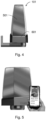
- the antenna is mounted on a base 601 in a cap 501.
- Base 601 may advantageously accommodate electronics 401 for the connection to bus 4, and possibly accessory/expansion boards.
- Bluetooth and Wi-Fi are indeed devices installed on the automation (motor) and therefore, may be shielded by obstacles such as the gate, walls, etc.
- a PIR i.e. an infrared presence detection sensor, both for alarm purposes and for activating a light or a camera with settable intervention times.
- the advantage is obtained of reducing the number of accessories to be connected to the automatism, with apparent reduction in costs and wiring.
- the control unit 201 of the signaling device 1 may also advantageously be programed to set the lighting element 101 so as to emit a light pattern which encodes a type of malfunction or anomaly. This may be particularly advantageous when technical maintenance is provided.
- a portable device such as a smartphone or a tablet, provided with camera for the optical reading of the light pattern emitted by the signaling device and a table for transcoding light codes to allow an operator to interpret the type of malfunction signaled by the signaling device.
- the display of the graphic codes which may be interpreted with the use of augmented reality via the smartphone, is a method for simplifying and making more efficient the work of the installer and the maintenance provided.
Landscapes
- Physics & Mathematics (AREA)
- Electromagnetism (AREA)
- General Physics & Mathematics (AREA)
- Circuit Arrangement For Electric Light Sources In General (AREA)
Description
- The invention relates to the field of the automation of doors, gates, and similar barrier devices conventionally employed to close access points, for example to garages or, more generally, to delimited areas.
- Nowadays, all the automations for managing opening and closing an access point provide the use of light-signaling devices, commonly called flash apparatuses, which signal when an automation is moving to open or close the access point with which it is associated.
- Such devices are also sold and currently installed by the Applicant. An example is the component belonging to the series called KIARO in the current sales catalog available on the Internet.
- Although they serve their function very well, these devices are limited to providing an indication of movement in a non-differentiated manner. For example, they do not indicate whether the barrier is opening or closing or when it is sufficiently open to allow going through the access point.
- Often, for example in case of company accesses controlled by gates controlled by security personnel, a driver sees the flashing apparatus turned ON and therefore readies to enter, thinking that such a signal means that the gate was opened and is waiting for transit, while in truth, the exact opposite is happening, i.e. the gate is closing again. This may be dangerous, in particular with large vehicles which may interfere with the gate also in the initial steps of the movement thereof.
- Document
DE202011103660U1 discloses an example of a signaling device and an associated control device for signaling the departure time of public transport, in particular rail vehicles, and a means of transport with such a signaling device. - It is the object of the present invention to provide a light-signaling device which increases the safety level of the automation with which it is associated or associable.
- The invention achieves the object with a light-signaling device according to
claim 1. - The lighting element may advantageously comprise a plurality of light sources, for example RGB LEDs arranged on a support having any shape, e.g. circular, which can be controlled by the control unit individually or in blocks to create light patterns which encode information on the status of the automation with which the signaling device is associated or associable, or simple lighting or guiding functionalities.
- Thereby, the light signaling may exploited to provide indications on the status of the automation, such as: in opening, in closing, automation awaiting maintenance and the like.
- The control unit may for example be programed to set the lighting element so as to emit a flashing light with a frequency which encodes a type of malfunction or anomaly. This is particularly advantageous when maintenance is provided because a device, such as a smartphone or a tablet, is sufficient to interpret the malfunction message on the basis of a reading of the light signal performed with the camera and a table for transcoding the messages.
- The signaling device may advantageously be used as hub for other devices, given that it is provided with a communication port and comprises an antenna mounted on the support and interface electronics towards said antenna. The interface may advantageously be in communication with the control unit to exchange data via the communication port so as to obtain a wireless communication gateway module. A presence detector, such as a passive infrared sensor PIR, is an example of another device which may be connected to the signaling device.
- According to another aspect, the invention relates to a system for controlling the movement of a movable access point such as a gate, a barrier, a door and the like, the system comprising:
- a motor for moving the opening automation/in closing;
- a control device of said motor;
- a port for receiving a movement command for the automation;
- a communication system;
- a central control unit provided with an interface for communicating with the motor control device and with the communication system, configured to receive movement commands of the automation from the input and accordingly send actuation signals to said motor control device;
- a light-signaling device according to the invention, interfaced with the central unit via the communication system so that the central unit can send commands to said signaling device.
- The central unit may advantageously be programed to send commands corresponding to system statuses to the signaling device so that the signaling device may accordingly emit a light with a light pattern, color and/or frequency which encodes the system status in the form of light message to send to a user.
- The signaling device control unit may be, for example programed to set the lighting element so as to emit a light of a first color, e.g. red, when the central unit controls the closing automation, of a second color, e.g. green, when the central unit controls the opening automation.
- The typical operation is the following: the central control unit may receive commands from various sources: such as, for example Command input (terminals), BUS communication port, Radio. After receiving the commands, the central control unit acts on the motor control device and may send commands to the signaling device control unit via the BUS communication port.
- In a variant, the control commands may be sent in the form of a single message or of various messages both to the motor control device of the automation and to the lighting device, via said communication system.
- In another configuration, the signaling device control unit may be programed to set the lighting element so as to emit a flashing light during the opening or the closing of the automation.
- The communication system may advantageously be a bus communication system with a master/slave type protocol, with the central unit being the master, the motor control device (in those configurations not providing for the motor control device to be integrated in the central control unit) and the signaling device being corresponding slaves which receive commands from, and send statuses to, said master.
- By taking advantage of the communication system, it may be provided for the signaling device to comprise one or more interfaces so as to form a hub for connecting with other devices which communicate with the central unit via the control unit and the communication bus.
- One of said other devices may be an antenna and the corresponding control electronics so as to associate the signaling device with a wireless gateway functionality.
- Further objects, features and advantages of the present invention will be more apparent from the following detailed description provided by way of nonlimiting example and illustrated in the accompanying figures, in which:
-
Figure 1 shows an exemplary diagram of the signaling device according to an embodiment of the invention. -
Figure 2 shows an exemplary diagram of the signaling device according to another embodiment of the invention. -
Figure 3 shows the device of the preceding drawings integrated in a system for controlling the movement of a movable access point. -
Figure 4 shows a section of the device according to the invention, in an embodiment with support for an antenna for wireless communication. -
Figure 5 shows a smartphone provided with apps for reading and interpreting light codes emitted by the device according to the invention. - With reference to the block diagram in
Figure 1 , thesignaling device 1 according to an embodiment of the invention comprises alighting element 101 mounted on a support, acommunication port 301 for receiving an ON/OFF command of thelighting element 101, and acontrol unit 201 in communication with thecommunication port 301 and thelighting element 101. - The
lighting element 101 may advantageously comprise a plurality of light sources, for example RGB LEDs arranged on a support having any shape, e.g. circular as in the drawing, which can be controlled by thecontrol unit 201 individually or in blocks to create light patterns of the most varied types in terms of shape, color, intensity, flashing frequency, according to commands which can be set from the outside via thecommunication port 301. - Thereby, the light signaling may exploited to provide indications on the status of the automation movement system. For example, light codes may be set, which signal: opening automation, closing automation, operating anomaly, malfunction, automation awaiting maintenance, time prior to scheduled maintenance and other similar operating statuses.
- An example may be a streetlight configuration in which different colors are used according to the status of the automation of the access point with which the device is associated (opening, closing, forbidden passageway, free passageway). The color red may, for example identify a circumstance of forbidden passageway, green a circumstance of free passageway, while a flashing red color could be employed to identify an opening automation, while a flashing red color could indicate a closing automation.
- Obviously, any type, color tone and flashing may be employed to signal the status of the automation with which the device is associated.
- The commands to the
communication port 301 may be sent manually or via remote interfaces. In a particularly advantageous configuration, such commands are sent by the same central unit which monitors the operation of the automation system, in particular by taking advantage of said communication bus between central unit and system actuation/sensor devices. -
Figure 3 shows an example of a system for controlling the movement of a movable access point, such as a gate, a barrier, a door and the like, in which the signaling device according to the invention may be used. The system comprises abus system 4 to which amovement module 2 for opening/closing the automation, acentral control module 3 and asignaling device 1 according to the invention, are connected. Themodules - The
movement module 2 comprises amotor 102, amotor control device 202, and aport 302 for receiving a barrier movement command viabus 4. - The
central control module 3 comprises acentral unit 103, aninput 203, and aninterface port 303 towardsbus 4. - The
central unit 103 is configured to read movement commands of the automation frominput 203 and/or frombus 4, and accordingly to send actuation signals to themotor control device 202 viabus 4. - The light-
signaling device 1 according to the invention is also interfaced with thecentral unit 103 via thebus communication system 4 so that thecentral unit 103 may send commands also to thesignaling device 1, in particular to thecontrol unit 201 thereof, via thecommunication port 301. - The
central unit 103 may advantageously be programed to send commands to thesignaling device 1 corresponding to system statuses so that thesignaling device 1 may accordingly emit a light with a light pattern, color and/or frequency which encodes the system status in the form of light message to send to a user. - The
control unit 201 of thesignaling device 1 may be, for example programed to set thelighting element 101 so as to emit a light of a first color, e.g. red, when the central unit controls the closing automation, of a second color, e.g. green, when the central unit controls the opening automation. The drive commands may be sent in the form of a single message or of various messages both to thecontrol device 202 ofmotor 102 of the automation and to thelighting device 1, via saidcommunication system 4. - In another configuration, the
control unit 201 of thesignaling device 1 may be programed to set thelighting element 101 so as to emit a flashing light during the opening or the closing of the barrier. - The
communication system 4 may advantageously be a bus communication system with a master/slave type protocol, with thecentral unit 103 being the master, themotor control device 2 and thesignaling device 1 being corresponding slaves which receive commands from, and send statuses to, said master. There may be further slave devices interfaced with the bus such as, for example photocell safety devices, sensitive edge safety devices, footboard-operated presence detectors, radar presence detectors and other devices typical of this type of systems. Thesame input 203 of thecentral unit 3 may be supported or replaced by a slave type input device interfaced with thecentral unit 3 viabus 4, e.g. a key selector switch, a control keypad, a remote control receiver and similar devices. - As shown in
Figure 2 , by taking advantage of thecommunication system 4, it may be provided for thesignaling device 1 to comprise one ormore interfaces 401 so as to form a hub for connecting with other devices which communicate with thecentral unit 103 via thecontrol unit 201 and thecommunication bus 4. - One of said other devices may be an antenna and the corresponding control electronics so as to associate the
signaling device 1 with a wireless gateway functionality, for example AF, Wi-Fi, Bluetooth, Zigbee, GPRS, UMTS, LTE and the like. In the configuration shown inFigure 4 , the antenna is mounted on a base 601 in acap 501.Base 601 may advantageously accommodateelectronics 401 for the connection tobus 4, and possibly accessory/expansion boards. - The use of the flasher as hub allows improving the radio performance. Usually, Bluetooth and Wi-Fi are indeed devices installed on the automation (motor) and therefore, may be shielded by obstacles such as the gate, walls, etc.
- Another device which may be interfaced with the
signaling device 1 is a PIR, i.e. an infrared presence detection sensor, both for alarm purposes and for activating a light or a camera with settable intervention times. - More generally, by integrating several functionalities in the signaling device, the advantage is obtained of reducing the number of accessories to be connected to the automatism, with apparent reduction in costs and wiring.
- The
control unit 201 of thesignaling device 1 may also advantageously be programed to set thelighting element 101 so as to emit a light pattern which encodes a type of malfunction or anomaly. This may be particularly advantageous when technical maintenance is provided. As shown inFigure 5 , indeed it is sufficient to employ a portable device, such as a smartphone or a tablet, provided with camera for the optical reading of the light pattern emitted by the signaling device and a table for transcoding light codes to allow an operator to interpret the type of malfunction signaled by the signaling device. The display of the graphic codes, which may be interpreted with the use of augmented reality via the smartphone, is a method for simplifying and making more efficient the work of the installer and the maintenance provided.
Claims (15)
- A light-signaling device for access points provided with automations, such as gates and/or automatic barriers, comprising:a lighting element (101);a communication port (301) for receiving commands for the lighting element;a control unit (201) in communication with said communication port (301) and said lighting element (101), said control unit (201) being configured to read the commands from the communication port (301) and accordingly to control the lighting element (101) so as to set light patterns having different shape and/or color and/or intensity on the basis of the commands received,characterized in thatit further comprises an antenna (501) mounted on a support (601) and interface electronics (401) towards said antenna (501), said interface electronics being in communication with the control unit (201) to exchange data via the communication port (301) so as to form a wireless communication gateway module, for example according to Wi-Fi, Bluetooth, Zigbee, GPRS, UMTS, LTE protocols and the like.
- A device according to claim 1, wherein the lighting element (101) comprises a plurality of light sources which can be driven by the control unit (201) individually or in blocks to create light patterns which encode information on the status of the automation with which the light-signalling device (1) is associated or associable, or simple lighting or guiding functionalities.
- A device according to claim 2, wherein said status information is selected from the group consisting of: opening automation, closing automation, operating anomaly, malfunction, automation awaiting maintenance, time prior to scheduled maintenance.
- A device according to one or more of the preceding claims, wherein the control unit (201) is programed to set the lighting element (101) so as to emit a flashing light with a frequency which encodes a type of malfunction or anomaly.
- A device according to one or more of the preceding claims, wherein the lighting element comprises a matrix of RGB LEDs arranged on a support having any shape.
- A system for controlling the movement of a movable automation for access points such as a gate, a barrier, a door and the like, the system comprising:a motor (102) for opening and closing the automation;a control device (202) of said motor (102);a port (302) for receiving movement commands for the automation;a communication system (4);a central control unit (103) in communication with an input (203) of said control device (202) via an interface (303) with the communication system (4), said central control unit (103) being configured to read the movement commands for the automation from the input (203) and accordingly send actuation signals to said motor control device (202),characterized in that it comprises a light-signaling device (1) according any one of claims 1 to 5, said light-signalling device (1) being interfaced with the central control unit (103) via the communication system (4) so that the central control unit (103) can send the commands for the lighting element to said light-signalling device (1).
- A system according to claim 6, wherein the central control unit (103) is programed to send the commands to the light-signalling device (1) corresponding to system statuses so that the light-signalling device (1) may accordingly emit a light with an intensity, color and/or frequency pattern that encodes the system status in the form of a light message to send to a user.
- A system according to claim 6 or 7, wherein the control unit (201) of the light-signalling device (1) is programed to set the lighting element (101) so as to emit a light of a first color, e.g. red, when the central unit (103) controls the closing of the automation, of a second color, e.g. green, when the central unit (103) controls the opening of the automation, said commands being sent in the form of a single message or of various messages both to the motor control device (202) of the automation and to the control unit (201) of the lighting device (1), via said communication system (4).
- A system according to one or more of preceding claims 6 to 8, wherein the control unit (201) of the light-signalling device (1) is programed to set the lighting element (101) so as to emit a flashing light during the opening or the closing of the automation.
- A system according to one or more of preceding claims 6 to 9, wherein the communication system (4) is a bus communication system with a master/slave type protocol, the central control unit (103) being the master, the motor control device (202) and the light-signalling device (1) being corresponding slaves which receive commands from, and send statuses to said master.
- A system according to claim 10, wherein the light-signalling device (1) comprises one or more interfaces (401) so as to form a hub for connecting with other devices which communicate with the central control unit (103) via the control unit (201) and the communication bus (4).
- A system according to claim 11, wherein one of said other devices is said antenna (501) and corresponding said interface electronics which allows the light-signalling device (1) to be associated with a wireless gateway functionality.
- A system according to one or more of preceding claims 6 to 12, wherein the control unit (201) of the light-signalling device (1) is programed to set the lighting element so as to emit a light pattern which encodes a type of malfunction or an anomaly.
- A system according to claim 13, further comprising a portable device for the optical reading of the light pattern emitted by the light-signalling device, said portable device having a table for transcoding the light pattern to allow an operator to interpret the type of malfunction signaled by the light-signalling device.
- A system according to claim 14, wherein the portable device is a smartphone or a tablet provided with a camera with which to read the light code emitted by the light-signalling device.
Priority Applications (2)
| Application Number | Priority Date | Filing Date | Title |
|---|---|---|---|
| PL21150472.5T PL4027313T3 (en) | 2021-01-07 | 2021-01-07 | Light-signaling device for access points |
| EP21150472.5A EP4027313B1 (en) | 2021-01-07 | 2021-01-07 | Light-signaling device for access points |
Applications Claiming Priority (1)
| Application Number | Priority Date | Filing Date | Title |
|---|---|---|---|
| EP21150472.5A EP4027313B1 (en) | 2021-01-07 | 2021-01-07 | Light-signaling device for access points |
Publications (2)
| Publication Number | Publication Date |
|---|---|
| EP4027313A1 EP4027313A1 (en) | 2022-07-13 |
| EP4027313B1 true EP4027313B1 (en) | 2024-05-29 |
Family
ID=74853505
Family Applications (1)
| Application Number | Title | Priority Date | Filing Date |
|---|---|---|---|
| EP21150472.5A Revoked EP4027313B1 (en) | 2021-01-07 | 2021-01-07 | Light-signaling device for access points |
Country Status (2)
| Country | Link |
|---|---|
| EP (1) | EP4027313B1 (en) |
| PL (1) | PL4027313T3 (en) |
Citations (10)
| Publication number | Priority date | Publication date | Assignee | Title |
|---|---|---|---|---|
| WO2003104907A1 (en) | 2002-06-06 | 2003-12-18 | Mhouse Srl | Electrical system for controlling at least one gate or door or similar element of the type moved electrically |
| WO2005080728A2 (en) | 2004-02-19 | 2005-09-01 | Wayne-Dalton Corp. | Operating system for a motorized barrier operator with a radio frequency energized light kit and/or switch and methods for programming the same |
| WO2006133981A1 (en) | 2005-04-22 | 2006-12-21 | Nice Spa | Light-emitting device |
| WO2010095161A1 (en) | 2009-02-23 | 2010-08-26 | Rib S.R.L. | Signaling device in particular for automatic opening/closing systems |
| DE202011103660U1 (en) | 2010-09-16 | 2011-12-05 | Siemens Ag Österreich | signaling device |
| WO2016022534A2 (en) | 2014-08-06 | 2016-02-11 | Rite-Hite Holding Corporation | Methods and systems to indicate the status of door operations |
| US20160063823A1 (en) | 2014-09-02 | 2016-03-03 | Schneider Electric Industries Sas | Multicolor signal light and controlling method thereof |
| US9997070B1 (en) | 2017-05-18 | 2018-06-12 | Abl Ip Holding Llc | Use of software configurable luminaire in parking application |
| US10087673B1 (en) | 2015-03-13 | 2018-10-02 | Gto Access Systems, Llc | Apparatus and techniques for door opener systems |
| WO2018185019A1 (en) | 2017-04-07 | 2018-10-11 | Hörmann KG Antriebstechnik | Closure drive device, closure having said closure drive device and operating method |
-
2021
- 2021-01-07 EP EP21150472.5A patent/EP4027313B1/en not_active Revoked
- 2021-01-07 PL PL21150472.5T patent/PL4027313T3/en unknown
Patent Citations (10)
| Publication number | Priority date | Publication date | Assignee | Title |
|---|---|---|---|---|
| WO2003104907A1 (en) | 2002-06-06 | 2003-12-18 | Mhouse Srl | Electrical system for controlling at least one gate or door or similar element of the type moved electrically |
| WO2005080728A2 (en) | 2004-02-19 | 2005-09-01 | Wayne-Dalton Corp. | Operating system for a motorized barrier operator with a radio frequency energized light kit and/or switch and methods for programming the same |
| WO2006133981A1 (en) | 2005-04-22 | 2006-12-21 | Nice Spa | Light-emitting device |
| WO2010095161A1 (en) | 2009-02-23 | 2010-08-26 | Rib S.R.L. | Signaling device in particular for automatic opening/closing systems |
| DE202011103660U1 (en) | 2010-09-16 | 2011-12-05 | Siemens Ag Österreich | signaling device |
| WO2016022534A2 (en) | 2014-08-06 | 2016-02-11 | Rite-Hite Holding Corporation | Methods and systems to indicate the status of door operations |
| US20160063823A1 (en) | 2014-09-02 | 2016-03-03 | Schneider Electric Industries Sas | Multicolor signal light and controlling method thereof |
| US10087673B1 (en) | 2015-03-13 | 2018-10-02 | Gto Access Systems, Llc | Apparatus and techniques for door opener systems |
| WO2018185019A1 (en) | 2017-04-07 | 2018-10-11 | Hörmann KG Antriebstechnik | Closure drive device, closure having said closure drive device and operating method |
| US9997070B1 (en) | 2017-05-18 | 2018-06-12 | Abl Ip Holding Llc | Use of software configurable luminaire in parking application |
Also Published As
| Publication number | Publication date |
|---|---|
| PL4027313T3 (en) | 2024-09-02 |
| EP4027313A1 (en) | 2022-07-13 |
Similar Documents
| Publication | Publication Date | Title |
|---|---|---|
| KR200394747Y1 (en) | The Control System for a numerous Lighting | |
| US10443296B2 (en) | Apparatus and techniques for door opener systems | |
| CA3071985A1 (en) | Methods and systems for decentralized train control | |
| US20050104745A1 (en) | Emergency vehicle traffic signal preemption system | |
| AU2010311317B2 (en) | Arrangement for passage control of mining vehicles | |
| US20080218380A1 (en) | Distributed Intelligence For Traffic Signal Control | |
| CN101739780A (en) | Warning light device having at least two warning lamps | |
| US11040841B2 (en) | Bollard with integrated control system | |
| EP3305034B1 (en) | Improvements in or relating to luminaires | |
| US5973616A (en) | Pager supported traffic signal controller | |
| US20150326314A1 (en) | Tandem, Visible Light and RF Communication System | |
| EP4027313A1 (en) | Light-signaling device for access points | |
| US10081318B2 (en) | Method and apparatus for operating a motor vehicle | |
| CN108121283B (en) | Intelligent auxiliary device for opening and closing control of inland river ship lock and use method | |
| WO2010013043A1 (en) | Method and device for vehicle identification and immobilisation | |
| CN214273738U (en) | Tunnel vehicle collision early warning device based on attitude sensor | |
| JP5454551B2 (en) | Traffic signal information providing system and information providing apparatus | |
| AU2015200518B2 (en) | Controller for operating a closure | |
| KR20060134238A (en) | System to control multiple lights | |
| CN215182175U (en) | Gate controller and control system | |
| AU2018315235B2 (en) | Temporary traffic signalling system | |
| CN112767716B (en) | Intelligent road signal machine with signal lamp wireless interaction | |
| JP2948811B1 (en) | Remote control transmitter for automatic switchgear | |
| KR19990075553A (en) | Wireless traffic control signal control method and device | |
| KR101457033B1 (en) | On-and-Off Light Remote Control Method and thereof Remote Control Apparatus |
Legal Events
| Date | Code | Title | Description |
|---|---|---|---|
| PUAI | Public reference made under article 153(3) epc to a published international application that has entered the european phase |
Free format text: ORIGINAL CODE: 0009012 |
|
| STAA | Information on the status of an ep patent application or granted ep patent |
Free format text: STATUS: THE APPLICATION HAS BEEN PUBLISHED |
|
| AK | Designated contracting states |
Kind code of ref document: A1 Designated state(s): AL AT BE BG CH CY CZ DE DK EE ES FI FR GB GR HR HU IE IS IT LI LT LU LV MC MK MT NL NO PL PT RO RS SE SI SK SM TR |
|
| STAA | Information on the status of an ep patent application or granted ep patent |
Free format text: STATUS: REQUEST FOR EXAMINATION WAS MADE |
|
| 17P | Request for examination filed |
Effective date: 20230111 |
|
| RBV | Designated contracting states (corrected) |
Designated state(s): AL AT BE BG CH CY CZ DE DK EE ES FI FR GB GR HR HU IE IS IT LI LT LU LV MC MK MT NL NO PL PT RO RS SE SI SK SM TR |
|
| P01 | Opt-out of the competence of the unified patent court (upc) registered |
Effective date: 20230525 |
|
| GRAP | Despatch of communication of intention to grant a patent |
Free format text: ORIGINAL CODE: EPIDOSNIGR1 |
|
| STAA | Information on the status of an ep patent application or granted ep patent |
Free format text: STATUS: GRANT OF PATENT IS INTENDED |
|
| RIC1 | Information provided on ipc code assigned before grant |
Ipc: G08B 5/38 20060101ALI20231205BHEP Ipc: G08B 5/36 20060101AFI20231205BHEP |
|
| INTG | Intention to grant announced |
Effective date: 20231222 |
|
| GRAS | Grant fee paid |
Free format text: ORIGINAL CODE: EPIDOSNIGR3 |
|
| GRAA | (expected) grant |
Free format text: ORIGINAL CODE: 0009210 |
|
| STAA | Information on the status of an ep patent application or granted ep patent |
Free format text: STATUS: THE PATENT HAS BEEN GRANTED |
|
| AK | Designated contracting states |
Kind code of ref document: B1 Designated state(s): AL AT BE BG CH CY CZ DE DK EE ES FI FR GB GR HR HU IE IS IT LI LT LU LV MC MK MT NL NO PL PT RO RS SE SI SK SM TR |
|
| REG | Reference to a national code |
Ref country code: CH Ref legal event code: EP |
|
| REG | Reference to a national code |
Ref country code: IE Ref legal event code: FG4D |
|
| REG | Reference to a national code |
Ref country code: DE Ref legal event code: R096 Ref document number: 602021013677 Country of ref document: DE |
|
| REG | Reference to a national code |
Ref country code: LT Ref legal event code: MG9D |
|
| REG | Reference to a national code |
Ref country code: NL Ref legal event code: MP Effective date: 20240529 |
|
| PG25 | Lapsed in a contracting state [announced via postgrant information from national office to epo] |
Ref country code: IS Free format text: LAPSE BECAUSE OF FAILURE TO SUBMIT A TRANSLATION OF THE DESCRIPTION OR TO PAY THE FEE WITHIN THE PRESCRIBED TIME-LIMIT Effective date: 20240929 |
|
| PG25 | Lapsed in a contracting state [announced via postgrant information from national office to epo] |
Ref country code: BG Free format text: LAPSE BECAUSE OF FAILURE TO SUBMIT A TRANSLATION OF THE DESCRIPTION OR TO PAY THE FEE WITHIN THE PRESCRIBED TIME-LIMIT Effective date: 20240529 |
|
| PG25 | Lapsed in a contracting state [announced via postgrant information from national office to epo] |
Ref country code: FI Free format text: LAPSE BECAUSE OF FAILURE TO SUBMIT A TRANSLATION OF THE DESCRIPTION OR TO PAY THE FEE WITHIN THE PRESCRIBED TIME-LIMIT Effective date: 20240529 Ref country code: HR Free format text: LAPSE BECAUSE OF FAILURE TO SUBMIT A TRANSLATION OF THE DESCRIPTION OR TO PAY THE FEE WITHIN THE PRESCRIBED TIME-LIMIT Effective date: 20240529 |
|
| PG25 | Lapsed in a contracting state [announced via postgrant information from national office to epo] |
Ref country code: GR Free format text: LAPSE BECAUSE OF FAILURE TO SUBMIT A TRANSLATION OF THE DESCRIPTION OR TO PAY THE FEE WITHIN THE PRESCRIBED TIME-LIMIT Effective date: 20240830 |
|
| REG | Reference to a national code |
Ref country code: AT Ref legal event code: MK05 Ref document number: 1691307 Country of ref document: AT Kind code of ref document: T Effective date: 20240529 |
|
| PG25 | Lapsed in a contracting state [announced via postgrant information from national office to epo] |
Ref country code: ES Free format text: LAPSE BECAUSE OF FAILURE TO SUBMIT A TRANSLATION OF THE DESCRIPTION OR TO PAY THE FEE WITHIN THE PRESCRIBED TIME-LIMIT Effective date: 20240529 |
|
| PG25 | Lapsed in a contracting state [announced via postgrant information from national office to epo] |
Ref country code: AT Free format text: LAPSE BECAUSE OF FAILURE TO SUBMIT A TRANSLATION OF THE DESCRIPTION OR TO PAY THE FEE WITHIN THE PRESCRIBED TIME-LIMIT Effective date: 20240529 |
|
| PG25 | Lapsed in a contracting state [announced via postgrant information from national office to epo] |
Ref country code: LV Free format text: LAPSE BECAUSE OF FAILURE TO SUBMIT A TRANSLATION OF THE DESCRIPTION OR TO PAY THE FEE WITHIN THE PRESCRIBED TIME-LIMIT Effective date: 20240529 |
|
| PG25 | Lapsed in a contracting state [announced via postgrant information from national office to epo] |
Ref country code: NO Free format text: LAPSE BECAUSE OF FAILURE TO SUBMIT A TRANSLATION OF THE DESCRIPTION OR TO PAY THE FEE WITHIN THE PRESCRIBED TIME-LIMIT Effective date: 20240829 Ref country code: LV Free format text: LAPSE BECAUSE OF FAILURE TO SUBMIT A TRANSLATION OF THE DESCRIPTION OR TO PAY THE FEE WITHIN THE PRESCRIBED TIME-LIMIT Effective date: 20240529 Ref country code: IS Free format text: LAPSE BECAUSE OF FAILURE TO SUBMIT A TRANSLATION OF THE DESCRIPTION OR TO PAY THE FEE WITHIN THE PRESCRIBED TIME-LIMIT Effective date: 20240929 Ref country code: HR Free format text: LAPSE BECAUSE OF FAILURE TO SUBMIT A TRANSLATION OF THE DESCRIPTION OR TO PAY THE FEE WITHIN THE PRESCRIBED TIME-LIMIT Effective date: 20240529 Ref country code: GR Free format text: LAPSE BECAUSE OF FAILURE TO SUBMIT A TRANSLATION OF THE DESCRIPTION OR TO PAY THE FEE WITHIN THE PRESCRIBED TIME-LIMIT Effective date: 20240830 Ref country code: FI Free format text: LAPSE BECAUSE OF FAILURE TO SUBMIT A TRANSLATION OF THE DESCRIPTION OR TO PAY THE FEE WITHIN THE PRESCRIBED TIME-LIMIT Effective date: 20240529 Ref country code: ES Free format text: LAPSE BECAUSE OF FAILURE TO SUBMIT A TRANSLATION OF THE DESCRIPTION OR TO PAY THE FEE WITHIN THE PRESCRIBED TIME-LIMIT Effective date: 20240529 Ref country code: BG Free format text: LAPSE BECAUSE OF FAILURE TO SUBMIT A TRANSLATION OF THE DESCRIPTION OR TO PAY THE FEE WITHIN THE PRESCRIBED TIME-LIMIT Effective date: 20240529 Ref country code: AT Free format text: LAPSE BECAUSE OF FAILURE TO SUBMIT A TRANSLATION OF THE DESCRIPTION OR TO PAY THE FEE WITHIN THE PRESCRIBED TIME-LIMIT Effective date: 20240529 Ref country code: RS Free format text: LAPSE BECAUSE OF FAILURE TO SUBMIT A TRANSLATION OF THE DESCRIPTION OR TO PAY THE FEE WITHIN THE PRESCRIBED TIME-LIMIT Effective date: 20240829 |
|
| PG25 | Lapsed in a contracting state [announced via postgrant information from national office to epo] |
Ref country code: NL Free format text: LAPSE BECAUSE OF FAILURE TO SUBMIT A TRANSLATION OF THE DESCRIPTION OR TO PAY THE FEE WITHIN THE PRESCRIBED TIME-LIMIT Effective date: 20240529 |
|
| PG25 | Lapsed in a contracting state [announced via postgrant information from national office to epo] |
Ref country code: NL Free format text: LAPSE BECAUSE OF FAILURE TO SUBMIT A TRANSLATION OF THE DESCRIPTION OR TO PAY THE FEE WITHIN THE PRESCRIBED TIME-LIMIT Effective date: 20240529 |
|
| PG25 | Lapsed in a contracting state [announced via postgrant information from national office to epo] |
Ref country code: DK Free format text: LAPSE BECAUSE OF FAILURE TO SUBMIT A TRANSLATION OF THE DESCRIPTION OR TO PAY THE FEE WITHIN THE PRESCRIBED TIME-LIMIT Effective date: 20240529 |
|
| PG25 | Lapsed in a contracting state [announced via postgrant information from national office to epo] |
Ref country code: EE Free format text: LAPSE BECAUSE OF FAILURE TO SUBMIT A TRANSLATION OF THE DESCRIPTION OR TO PAY THE FEE WITHIN THE PRESCRIBED TIME-LIMIT Effective date: 20240529 |
|
| PG25 | Lapsed in a contracting state [announced via postgrant information from national office to epo] |
Ref country code: CZ Free format text: LAPSE BECAUSE OF FAILURE TO SUBMIT A TRANSLATION OF THE DESCRIPTION OR TO PAY THE FEE WITHIN THE PRESCRIBED TIME-LIMIT Effective date: 20240529 |
|
| PG25 | Lapsed in a contracting state [announced via postgrant information from national office to epo] |
Ref country code: SK Free format text: LAPSE BECAUSE OF FAILURE TO SUBMIT A TRANSLATION OF THE DESCRIPTION OR TO PAY THE FEE WITHIN THE PRESCRIBED TIME-LIMIT Effective date: 20240529 Ref country code: RO Free format text: LAPSE BECAUSE OF FAILURE TO SUBMIT A TRANSLATION OF THE DESCRIPTION OR TO PAY THE FEE WITHIN THE PRESCRIBED TIME-LIMIT Effective date: 20240529 |
|
| PG25 | Lapsed in a contracting state [announced via postgrant information from national office to epo] |
Ref country code: SM Free format text: LAPSE BECAUSE OF FAILURE TO SUBMIT A TRANSLATION OF THE DESCRIPTION OR TO PAY THE FEE WITHIN THE PRESCRIBED TIME-LIMIT Effective date: 20240529 |
|
| PG25 | Lapsed in a contracting state [announced via postgrant information from national office to epo] |
Ref country code: SM Free format text: LAPSE BECAUSE OF FAILURE TO SUBMIT A TRANSLATION OF THE DESCRIPTION OR TO PAY THE FEE WITHIN THE PRESCRIBED TIME-LIMIT Effective date: 20240529 Ref country code: SK Free format text: LAPSE BECAUSE OF FAILURE TO SUBMIT A TRANSLATION OF THE DESCRIPTION OR TO PAY THE FEE WITHIN THE PRESCRIBED TIME-LIMIT Effective date: 20240529 Ref country code: RO Free format text: LAPSE BECAUSE OF FAILURE TO SUBMIT A TRANSLATION OF THE DESCRIPTION OR TO PAY THE FEE WITHIN THE PRESCRIBED TIME-LIMIT Effective date: 20240529 Ref country code: EE Free format text: LAPSE BECAUSE OF FAILURE TO SUBMIT A TRANSLATION OF THE DESCRIPTION OR TO PAY THE FEE WITHIN THE PRESCRIBED TIME-LIMIT Effective date: 20240529 Ref country code: DK Free format text: LAPSE BECAUSE OF FAILURE TO SUBMIT A TRANSLATION OF THE DESCRIPTION OR TO PAY THE FEE WITHIN THE PRESCRIBED TIME-LIMIT Effective date: 20240529 Ref country code: CZ Free format text: LAPSE BECAUSE OF FAILURE TO SUBMIT A TRANSLATION OF THE DESCRIPTION OR TO PAY THE FEE WITHIN THE PRESCRIBED TIME-LIMIT Effective date: 20240529 |
|
| REG | Reference to a national code |
Ref country code: DE Ref legal event code: R026 Ref document number: 602021013677 Country of ref document: DE |
|
| PLBI | Opposition filed |
Free format text: ORIGINAL CODE: 0009260 |
|
| PLAX | Notice of opposition and request to file observation + time limit sent |
Free format text: ORIGINAL CODE: EPIDOSNOBS2 |
|
| 26 | Opposition filed |
Opponent name: SOMFY ACTIVITES SA Effective date: 20250228 |
|
| PGFP | Annual fee paid to national office [announced via postgrant information from national office to epo] |
Ref country code: DE Payment date: 20241120 Year of fee payment: 5 |
|
| PG25 | Lapsed in a contracting state [announced via postgrant information from national office to epo] |
Ref country code: SI Free format text: LAPSE BECAUSE OF FAILURE TO SUBMIT A TRANSLATION OF THE DESCRIPTION OR TO PAY THE FEE WITHIN THE PRESCRIBED TIME-LIMIT Effective date: 20240529 |
|
| PLBB | Reply of patent proprietor to notice(s) of opposition received |
Free format text: ORIGINAL CODE: EPIDOSNOBS3 |
|
| REG | Reference to a national code |
Ref country code: CH Ref legal event code: PL |
|
| PG25 | Lapsed in a contracting state [announced via postgrant information from national office to epo] |
Ref country code: SE Free format text: LAPSE BECAUSE OF FAILURE TO SUBMIT A TRANSLATION OF THE DESCRIPTION OR TO PAY THE FEE WITHIN THE PRESCRIBED TIME-LIMIT Effective date: 20240529 |
|
| PG25 | Lapsed in a contracting state [announced via postgrant information from national office to epo] |
Ref country code: LU Free format text: LAPSE BECAUSE OF NON-PAYMENT OF DUE FEES Effective date: 20250107 Ref country code: MC Free format text: LAPSE BECAUSE OF FAILURE TO SUBMIT A TRANSLATION OF THE DESCRIPTION OR TO PAY THE FEE WITHIN THE PRESCRIBED TIME-LIMIT Effective date: 20240529 |
|
| PG25 | Lapsed in a contracting state [announced via postgrant information from national office to epo] |
Ref country code: CH Free format text: LAPSE BECAUSE OF NON-PAYMENT OF DUE FEES Effective date: 20250131 |
|
| RDAF | Communication despatched that patent is revoked |
Free format text: ORIGINAL CODE: EPIDOSNREV1 |
|
| REG | Reference to a national code |
Ref country code: DE Ref legal event code: R064 Ref document number: 602021013677 Country of ref document: DE Ref country code: DE Ref legal event code: R103 Ref document number: 602021013677 Country of ref document: DE |
|
| PGFP | Annual fee paid to national office [announced via postgrant information from national office to epo] |
Ref country code: GB Payment date: 20251113 Year of fee payment: 6 |
|
| PGFP | Annual fee paid to national office [announced via postgrant information from national office to epo] |
Ref country code: FR Payment date: 20251117 Year of fee payment: 6 |
|
| PGFP | Annual fee paid to national office [announced via postgrant information from national office to epo] |
Ref country code: BE Payment date: 20251223 Year of fee payment: 6 |
|
| PGFP | Annual fee paid to national office [announced via postgrant information from national office to epo] |
Ref country code: IE Payment date: 20251111 Year of fee payment: 6 |
|
| PGFP | Annual fee paid to national office [announced via postgrant information from national office to epo] |
Ref country code: PL Payment date: 20251104 Year of fee payment: 6 |
|
| RDAG | Patent revoked |
Free format text: ORIGINAL CODE: 0009271 |
|
| STAA | Information on the status of an ep patent application or granted ep patent |
Free format text: STATUS: PATENT REVOKED |
|
| REG | Reference to a national code |
Ref country code: CH Ref legal event code: N12 Free format text: ST27 STATUS EVENT CODE: U-0-0-N10-N12 (AS PROVIDED BY THE NATIONAL OFFICE) Effective date: 20260402 |
|
| PGFP | Annual fee paid to national office [announced via postgrant information from national office to epo] |
Ref country code: IT Payment date: 20251219 Year of fee payment: 6 |
|
| 27W | Patent revoked |
Effective date: 20251222 |
|
| GBPR | Gb: patent revoked under art. 102 of the ep convention designating the uk as contracting state |
Effective date: 20251222 |
|
| PG25 | Lapsed in a contracting state [announced via postgrant information from national office to epo] |
Ref country code: LT Free format text: LAPSE BECAUSE OF FAILURE TO SUBMIT A TRANSLATION OF THE DESCRIPTION OR TO PAY THE FEE WITHIN THE PRESCRIBED TIME-LIMIT Effective date: 20240529 |