EP4027084A2 - Transparent element system and refrigerating device - Google Patents
Transparent element system and refrigerating device Download PDFInfo
- Publication number
- EP4027084A2 EP4027084A2 EP22150469.9A EP22150469A EP4027084A2 EP 4027084 A2 EP4027084 A2 EP 4027084A2 EP 22150469 A EP22150469 A EP 22150469A EP 4027084 A2 EP4027084 A2 EP 4027084A2
- Authority
- EP
- European Patent Office
- Prior art keywords
- transparent element
- power
- unit
- power receiving
- receiving unit
- Prior art date
- Legal status (The legal status is an assumption and is not a legal conclusion. Google has not performed a legal analysis and makes no representation as to the accuracy of the status listed.)
- Pending
Links
Images




Classifications
-
- A—HUMAN NECESSITIES
- A47—FURNITURE; DOMESTIC ARTICLES OR APPLIANCES; COFFEE MILLS; SPICE MILLS; SUCTION CLEANERS IN GENERAL
- A47F—SPECIAL FURNITURE, FITTINGS, OR ACCESSORIES FOR SHOPS, STOREHOUSES, BARS, RESTAURANTS OR THE LIKE; PAYING COUNTERS
- A47F7/00—Show stands, hangers, or shelves, adapted for particular articles or materials
- A47F7/0071—Show stands, hangers, or shelves, adapted for particular articles or materials for perishable goods
-
- A—HUMAN NECESSITIES
- A47—FURNITURE; DOMESTIC ARTICLES OR APPLIANCES; COFFEE MILLS; SPICE MILLS; SUCTION CLEANERS IN GENERAL
- A47F—SPECIAL FURNITURE, FITTINGS, OR ACCESSORIES FOR SHOPS, STOREHOUSES, BARS, RESTAURANTS OR THE LIKE; PAYING COUNTERS
- A47F3/00—Show cases or show cabinets
- A47F3/04—Show cases or show cabinets air-conditioned, refrigerated
-
- A—HUMAN NECESSITIES
- A47—FURNITURE; DOMESTIC ARTICLES OR APPLIANCES; COFFEE MILLS; SPICE MILLS; SUCTION CLEANERS IN GENERAL
- A47F—SPECIAL FURNITURE, FITTINGS, OR ACCESSORIES FOR SHOPS, STOREHOUSES, BARS, RESTAURANTS OR THE LIKE; PAYING COUNTERS
- A47F3/00—Show cases or show cabinets
- A47F3/04—Show cases or show cabinets air-conditioned, refrigerated
- A47F3/0404—Cases or cabinets of the closed type
- A47F3/0426—Details
- A47F3/0434—Glass or transparent panels
-
- A—HUMAN NECESSITIES
- A47—FURNITURE; DOMESTIC ARTICLES OR APPLIANCES; COFFEE MILLS; SPICE MILLS; SUCTION CLEANERS IN GENERAL
- A47F—SPECIAL FURNITURE, FITTINGS, OR ACCESSORIES FOR SHOPS, STOREHOUSES, BARS, RESTAURANTS OR THE LIKE; PAYING COUNTERS
- A47F3/00—Show cases or show cabinets
- A47F3/12—Clamps or other devices for supporting, fastening, or connecting glass plates, panels or the like
- A47F3/125—Doors for show cases
-
- F—MECHANICAL ENGINEERING; LIGHTING; HEATING; WEAPONS; BLASTING
- F25—REFRIGERATION OR COOLING; COMBINED HEATING AND REFRIGERATION SYSTEMS; HEAT PUMP SYSTEMS; MANUFACTURE OR STORAGE OF ICE; LIQUEFACTION SOLIDIFICATION OF GASES
- F25D—REFRIGERATORS; COLD ROOMS; ICE-BOXES; COOLING OR FREEZING APPARATUS NOT OTHERWISE PROVIDED FOR
- F25D21/00—Defrosting; Preventing frosting; Removing condensed or defrost water
- F25D21/04—Preventing the formation of frost or condensate
-
- F—MECHANICAL ENGINEERING; LIGHTING; HEATING; WEAPONS; BLASTING
- F25—REFRIGERATION OR COOLING; COMBINED HEATING AND REFRIGERATION SYSTEMS; HEAT PUMP SYSTEMS; MANUFACTURE OR STORAGE OF ICE; LIQUEFACTION SOLIDIFICATION OF GASES
- F25D—REFRIGERATORS; COLD ROOMS; ICE-BOXES; COOLING OR FREEZING APPARATUS NOT OTHERWISE PROVIDED FOR
- F25D23/00—General constructional features
- F25D23/02—Doors; Covers
- F25D23/028—Details
-
- G—PHYSICS
- G08—SIGNALLING
- G08B—SIGNALLING SYSTEMS, e.g. PERSONAL CALLING SYSTEMS; ORDER TELEGRAPHS; ALARM SYSTEMS
- G08B21/00—Alarms responsive to a single specified undesired or abnormal condition and not otherwise provided for
- G08B21/18—Status alarms
- G08B21/24—Reminder alarms, e.g. anti-loss alarms
-
- F—MECHANICAL ENGINEERING; LIGHTING; HEATING; WEAPONS; BLASTING
- F25—REFRIGERATION OR COOLING; COMBINED HEATING AND REFRIGERATION SYSTEMS; HEAT PUMP SYSTEMS; MANUFACTURE OR STORAGE OF ICE; LIQUEFACTION SOLIDIFICATION OF GASES
- F25D—REFRIGERATORS; COLD ROOMS; ICE-BOXES; COOLING OR FREEZING APPARATUS NOT OTHERWISE PROVIDED FOR
- F25D2321/00—Details or arrangements for defrosting; Preventing frosting; Removing condensed or defrost water, not provided for in other groups of this subclass
Definitions
- the present invention relates to a transparent element system and a refrigerating device comprising the transparent element system.
- some refrigerators use glass as a material isolated from the outside, so as to facilitate the observation of the exhibits in the refrigerator from the outside.
- condensed water is easily formed on the surface of the glass due to the condensation of water vapor in the air, which will cause the observability of the glass to be reduced significantly.
- the accumulation of water stains is easy to breed bacteria, which is also detrimental to hygiene and health.
- a transparent element system comprising: a transparent element configured to allow light to penetrate; a power receiving unit configured to receive power in a wireless manner; and a heating unit attached to the transparent element and electrically connected to the power receiving unit, wherein the heating unit heats the transparent element by using the power received by the power receiving unit.
- Such an arrangement may thus provide a transparent element system and, optionally, a refrigerating device comprising the transparent element system that is advantageously configured for preventing condensation of water vapor on an observable surface such as the refrigerating device, thereby ensuring the internal observability of the device such as the refrigerating device.
- the transparent element may be referenced as a "perspective medium", and this term may optionally replace "transparent element" as referenced herein.
- the transparent element may advantageously be an element formed of at least partially transparent material(s) in order to permit at least partial viewing through the transparent element. This may be viewing of an of an interior that is at least in part enclosed by the transparent element, such as with the transparent element providing a window into an enclosed space.
- the transparent element may be fully transparent in the sense of providing a window allowing a person to view and identify objects the other side of the transparent element. It may be alternatively referred to as a transparent medium, and optionally could be a viewing window.
- the examples herein provide added detail of the possible function of the transparent element and degrees to which it provides transparency and the ability to see the interior.
- the transparent element can also incorporate non-transparent materials in a way that does not prevent viewing through the transparent element
- the transparent element comprises a plurality of layered structures, and the heating unit is disposed among the plurality of layered structures.
- the layered structures may comprise or consist of transparent structures.
- the degree of reduction in the light transmittance of the heating unit to the transparent element is less than a first preset value.
- the heating unit is evenly arranged among the plurality of layered structures.
- the system comprises, or further comprises: a transmittance estimating unit configured to evaluate the light transmittance of the transparent element; and the heating unit is configured to stop heating the transparent element if the light transmittance of the transparent element is higher than a second preset value.
- the system comprises, or further comprises: a reminding unit configured to send a reminder message when the light transmittance of the transparent element is less than or equal to the second preset value and the power receiving unit fails to receive power.
- a reminding unit configured to send a reminder message when the light transmittance of the transparent element is less than or equal to the second preset value and the power receiving unit fails to receive power.
- the transparent element comprises: glass, tempered glass, plexiglass, and coated glass.
- a refrigerating device comprising: one or more power transmitting units configured to transmit power in a wireless manner; and one or more of any one of the transparent element systems described above, wherein a power receiving unit of the transparent element system receives power from the power transmitting unit.
- the device comprises, or further comprises: a moving rail configured to be coupled to a sliding edge of the transparent element, thereby allowing the transparent element to move along its extension direction; wherein: the power transmitting unit is arranged around the moving rail; and the power receiving unit is arranged at the sliding edge.
- the power transmitting unit is configured to be set at intervals with a third preset value, and the third preset value is smaller than the width of the transparent element in the extension direction of the moving rail.
- a container comprising: a power receiving unit configured to receive power in a wireless manner; and a heating unit attached to an outer surface of the container and electrically connected to the power receiving unit, wherein the heating unit heats the outer surface of the container by using the power received by the power receiving unit.
- the container is a liquid bottle-shaped or cup-shaped container.
- the container may comprise of consist of a transparent element system as defined above, and thus may comprise a transparent element that is configured to allow light to penetrate.
- the heating unit may be attached to the transparent element and electrically connected to the power receiving unit, wherein the heating unit heats the transparent element by using the power received by the power receiving unit.
- the transparent element may form all of or a part of a wall of the container.
- the present application mainly refers to its exemplary embodiments to describe the principles of the present application.
- those skilled in the art will readily recognize that the same principles can be equally applied to all types of transparent element systems and refrigerating devices comprising transparent element systems, and these same or similar principles can be implemented therein, any such changes do not depart from the true spirit and scope of the present application.
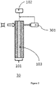
- the transparent element system 10 comprises a transparent element 101, a power receiving unit 102 and a heating unit 103.
- the transparent element 101 is configured to allow light to penetrate, thereby allowing objects on the other side to be observed from the transparent element 101.
- the transparent element 101 may be glass, tempered glass, plexiglass, coated glass (also known as Low-E glass), etc., or may be other transparent/translucent materials that can serve as air barrier/heat preservation but at least ensure certain optical penetration.
- the power receiving unit 102 of the transparent element system 10 is configured to receive power in a wireless manner.
- the power receiving unit 102 can be composed of a receiving coil and a corresponding processing circuit.
- the power receiving unit 102 can receive the power of the power and frequency meeting the preset requirements and use it as an energy source for other components of the transparent element system 10.
- the power receiving unit 102 can be configured as a wireless power receiving device that meets existing standards (for example, Qi) as needed, it can also be a wireless power receiving device that meets industrial or commercial de facto standards, and it can also be a customized wireless power receiving device that meets specific needs.
- the power receiving unit 102 needs to be used in conjunction with the power transmitting unit, the power transmitting unit is not necessarily used as a component of the transparent element system 10.
- the heating unit 103 of the transparent element system 10 is attached to the transparent element 101, and is electrically connected to the power receiving unit 102 (not shown in the figure). At the same time, the heating unit 103 heats the transparent element 101 by using the power received by the power receiving unit 102.
- the heating unit 103 is attached to one side surface of the transparent element 101, but the present application does not limit the way the heating unit 103 is attached to the transparent element 101, as long as the heating unit 103 can move relative to the transparent element 101 and heat the transparent element 101 (comprising its surface).
- the heating range of the transparent element 101 by the heating unit 103 can cover the entire surface, part of the surface, a designated area on the surface, etc. of the transparent element 101 as needed.
- the heating range in some examples of the present application refers to the range that the heating unit 103 can thermodynamically affect, and it is not necessary for the heating unit 103 to be in direct contact with all of these ranges.
- the heating unit 103 of the transparent element system 10 is electrically connected to the power receiving unit 102.
- the electrical connection in the example of the present application refers to a connection method that can realize power transmission.
- the heating unit 103 may be connected to the power receiving unit 102 via a length of wire.
- the heating element of the heating unit 103 as the conductor itself can also be directly connected to the power receiving unit 102 without a wire.
- the transparent element 101 comprises a plurality of perspective layered structures (the cross-sectional structure of the transparent element 101 shown in FIG. 1 ).
- the transparent element 101 shown in the figure comprises a three-layer structure, in which a first layer 101-1 is a hard glass layer, a second layer 101-2 is a glue layer, and a third layer 101-3 is a hard glass layer.
- the first layer 101-1 and the third layer 101-3 are glued together by the second layer 101-2 to form a complete transparent element 101.
- the heating unit 103 is arranged among a plurality of perspective layered structures.
- the heating unit 103 can be arranged between the first layer 101-1 and the third layer 101-3 and buried in the glue layer 101-2. Since heating elements such as heating wires are relatively weak, the heating unit 103 is embedded in the transparent element 101 in this example, which can prevent the heating unit 103 from being disabled by external force.
- the heating unit 103 selects a material that has less influence on light transmittance.
- the degree of reduction in the light transmittance of the heating unit 103 to the transparent element 101 is less than a first preset value.
- the heating unit 103 can be made of materials such as heating films (for example, metal film layers), heating wires, etc., and the light transmittance of the transparent element 101 is reduced below, for example, 5%, that is, the optical shielding caused by the shielding of the heating unit 103 does not exceed 5%.
- the heating unit 103 is evenly arranged among the plurality of perspective layered structures.
- the heating unit 103 is arranged in a regular geometric shape, and the heating material per unit area is made equal as much as possible. In this way, it can be ensured that the heating unit can uniformly heat the transparent element 101 within the range (the entire surface, part of the surface, a designated area on the surface, etc.) that needs to be heated by the heating unit, which is more conducive to the volatilization of water vapor condensate.
- the arrangement of the heating unit 103 may also be sparse and dense.
- the transparent element system used in the refrigerating device may not be installed horizontally. In this case, under the influence of gravity, the condensed water may flow down to a lower position of the transparent element. Water stains are more likely to accumulate in low places, and therefore require more heating. For this reason, the heating unit 103 may be gradually densely arranged along one direction, so that the heating material per unit area gradually increases along this direction. At this time, the surface of the transparent element 101 of the transparent element system 10 may be marked with a mark indicating that the heating unit 103 is arranged sparsely and densely. When it is necessary to install the transparent element system 10 in, for example, a refrigerating device, according to this mark, the side with more heating material per unit area can be installed at a lower place.
- the transparent element system 30 optionally comprises a transmittance estimating unit 301.
- the transparent element system may be both the transparent element system 10 and the transparent element system 30 unless otherwise specified or there is no possibility of implementation.
- the transmittance estimating unit 301 is configured to evaluate the light transmittance of the transparent element 101.
- a light source with a fixed intensity can be provided on one side of the transparent element 101 and light with a fixed intensity can be emitted to the other side.
- the light intensity sensing element of the transmittance estimating unit 301 is arranged on the opposite side of the light source, and is used to receive the light emitted by the light source.
- the light intensity sensing element evaluates the light transmittance of the transparent element 101 based on the received light intensity. For example, if the light intensity on one surface (incident side) is K lux, the light intensity detected on the other surface (exit side) is 0.9K lux, the light transmittance of the transparent element 101 is 90%. On the other hand, if the light transmittance of the transparent element 101 is higher, the heating can be stopped to save power consumption.
- the heating unit 103 is configured to stop heating the transparent element 101 when the light transmittance of the transparent element 101 is higher than a second preset value (for example, 85%).
- the transmittance estimating unit 301 can generate a control signal (for example, an on-off signal) accordingly and send it to a control device (not shown in the figure) that controls the on-off of the heating unit 103.
- a control signal for example, an on-off signal
- the transmittance estimating unit 301 may generate an on signal
- the transmittance estimating unit 301 may generate an off signal.
- the control device receives the on signal
- the heating unit 103 starts to work; and when the control device receives the off signal, the heating unit 103 stops working.
- the transparent element system 30 further comprises a reminding unit (not shown in the Figure).
- the reminding unit is configured to send a reminder message when the light transmittance of the transparent element 101 is less than or equal to the second preset value and the power receiving unit 102 fails to receive power.
- the light transmittance of the transparent element 101 is less than or equal to the second preset value, it indicates that the transparent element 101 needs to be heated to clean its surface.
- the power receiving unit 102 fails to receive power, or its matching power transmitting unit fails to transmit power, or the heating unit 103 fails to heat normally at present, it indicates that there is a special situation in the system that causes the heating unit 103 to fail to work according to the preset logic.
- Special situations may comprise the following: the power receiving unit 102 or its matching power transmitting unit is damaged, the power receiving unit 102 and its matching power transmitting unit cannot be aligned (the two are not within the effective working distance), and the heating unit 103 is damaged.
- the operator or the automated processing equipment should be reminded, for example, a reminder message should be sent to the operator or the automated processing equipment.
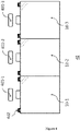
- the example refrigerating device 40 comprises one or more power transmitting units and one or more transparent element systems.
- the Figure shows three power transmitting units 401-1, 401-2 and 401-3 and three corresponding transparent element systems 10-1, 10-2 and 10-3. In actual use, the number of power transmitting unit and the transparent element system are not limited to three.
- the transparent element systems 10-1, 10-2, and 10-3 in the refrigerating device 40 may be configured according to the above-described transparent element system.
- the main components of the transparent element system can be integrated with the transparent element in the transparent element system, and thus the integral part is called the body of the transparent element system, sometimes referred to as the transparent element system for short, or also referred to as the transparent element.
- the power transmitting units 401-1, 401-2, and 401-3 are configured to transmit power in a wireless manner.
- the power transmitting units 401-1, 401-2, and 401-3 can be composed of a transmitting coil and a corresponding processing circuit.
- the power transmitting units 401-1, 401-2, and 401-3 can transmit the power of the power and frequency meeting the preset requirements and the power is received by the pre-set matching power receiving unit.
- the power transmitting units 401-1, 401-2, and 401-3 can be configured as wireless power transmitting device that meets existing standards (for example, Qi) as needed, it can also be a wireless power transmitting device that meets industrial or commercial de facto standards, and it can also be a customized wireless power transmitting device that meets specific needs.
- the power receiving units of the transparent element systems 10-1, 10-2, and 10-3 receive the power from the power transmitting unit, and serve as energy sources for other unit modules of the transparent element system.
- the transparent element of the transparent element systems 10-1, 10-2, and 10-3 is used as the perspective door of the refrigerating device 40, and the bodies of transparent element systems 10-1, 10-2, and 10-3 can be connected to the body of the refrigerating device 40 by means of a hinge 402, wherein two or more hinges are configured for each piece of transparent element. Since the power is transmitted between the power transmitting unit and the transparent element system in a wireless manner, compared with the wired method, the opening and closing state of the hinge 402 will not affect the stability of the transmission link.
- the power transmitting unit and the transparent element system can be configured to transmit power regardless of the opening and closing state of the hinge 402; in other examples, the power transmitting unit and the transparent element system can be configured to transmit power when the hinge 402 is in the preset opening and closing angle range.
- the refrigerating device 40 shown in FIG. 4 is an open-close door structure.
- the refrigerating device may also be a sliding door structure.
- the refrigerating device 50 comprises two upper and lower moving rails 501, and the moving rails for the body of transparent element system can realize the opening and closing of the refrigerating device 50 with the help of the moving rails 501.
- the moving rails 501 of the refrigerating device 50 are configured to be coupled to the sliding edge of the transparent element of the transparent element system, thereby allowing the transparent element to move along its extending direction.
- the sliding edge in the example of the present application refers to an edge in the transparent element that can slide along the moving rail, and the transparent element also comprises a non-sliding edge that does not slide on the moving rail.
- the power transmitting units 401-1, 401-2, and 401-3 of the refrigerating device 50 can be arranged around the moving rail, and the power receiving units of the transparent element systems 10-1, 10-2, and 10-3 are arranged at the sliding edge.
- the power transmitting unit and the power receiving unit are arranged in alignment, so as to ensure that the power transmitting unit and the power receiving unit can stably transmit power when the sliding door is at least in the default closed position.
- the transparent element system can also obtain power supply in other positions, for example, when the transparent element system 10-1 is moved to the position of the transparent element system 10-2 shown in the figure, the transparent element system 10-1 can also obtain power from the power transmitting unit 401-2.
- the power transmitting unit is arranged corresponding to the transparent element system (specifically, the power receiving unit).
- the transparent element system specifically, the power receiving unit.
- each dimension of the transparent element can be the same, and the position of the power receiving unit relative to the transparent element is also the same. Therefore, the interval of the power transmitting units 401-1, 401-2, and 401-3 can be roughly the same as the width of the transparent element in the extension direction of the moving rail.
- the power transmitting unit is configured to be set at intervals with a third preset value, where the third preset value is smaller than the width of the transparent element in the extension direction of the moving rail.
- the interval between the power transmitting units 601 shown in FIG. 6 is smaller than the interval between the power transmitting units shown in FIG 5 .
- the interval between the power transmitting units 601 of the refrigerating device 60 is half of the width of the transparent element in the extension direction of the moving rail.
- the energy transmission path can be established more easily between the power transmitting unit and the power receiving unit during the movement of the sliding door.
- the widths of the respective transparent element in the extension direction of the moving rail may not necessarily be equal, and the third preset value is smaller than the minimum value of the widths of the transparent element in the extension direction of the moving rail at this time.
- the sliding door of the refrigerating device may not move in a horizontal direction, and the sliding door may have a certain angle. In this case, due to gravity, the condensed water may flow to the lower position of the sliding door.
- the foregoing has introduced a transparent element system in which the heating units are gradually densely arranged in one direction, wherein the surface of the transparent element of the transparent element system may be marked with a mark indicating that the heating unit is arranged sparsely and densely.
- a container comprising an power receiving unit and a heating unit.
- the power receiving unit is configured to receive power in a wireless manner.
- the power receiving unit of the container can be arranged at the bottom of the container, so as to be conveniently placed on, for example, a wireless charging base to draw power.
- the heating unit is attached to the outer surface of the container, for example, to the outer surface of a container such as a cup.
- the heating unit is electrically connected to the power receiving unit, and heats the outer surface of the container by using the power received by the power receiving unit. Therefore, when a container such as a cup is placed on the wireless charging base, the outer surface of the cup can be automatically heated, thereby preventing the generation of condensed water or removing the condensed water.
- the container is a liquid bottle-shaped or cup-shaped container.
Landscapes
- Engineering & Computer Science (AREA)
- Physics & Mathematics (AREA)
- Thermal Sciences (AREA)
- Chemical & Material Sciences (AREA)
- Combustion & Propulsion (AREA)
- Mechanical Engineering (AREA)
- General Engineering & Computer Science (AREA)
- Business, Economics & Management (AREA)
- Emergency Management (AREA)
- General Physics & Mathematics (AREA)
- Devices That Are Associated With Refrigeration Equipment (AREA)
Abstract
Description
- The present invention relates to a transparent element system and a refrigerating device comprising the transparent element system.
- At present, some refrigerators use glass as a material isolated from the outside, so as to facilitate the observation of the exhibits in the refrigerator from the outside. However, condensed water is easily formed on the surface of the glass due to the condensation of water vapor in the air, which will cause the observability of the glass to be reduced significantly. In addition, the accumulation of water stains is easy to breed bacteria, which is also detrimental to hygiene and health.
- In the prior art, there is a technical solution for using cables to supply power to the heating film of the sliding glass door of the refrigerator. However, this cable-powered solution is likely to cause the cable to loosen after the glass door is slid multiple times. The insulation performance of the cable may also be damaged.
- According to an aspect of the present invention, there is provided a transparent element system, comprising: a transparent element configured to allow light to penetrate; a power receiving unit configured to receive power in a wireless manner; and a heating unit attached to the transparent element and electrically connected to the power receiving unit, wherein the heating unit heats the transparent element by using the power received by the power receiving unit.
- Such an arrangement may thus provide a transparent element system and, optionally, a refrigerating device comprising the transparent element system that is advantageously configured for preventing condensation of water vapor on an observable surface such as the refrigerating device, thereby ensuring the internal observability of the device such as the refrigerating device. In some instances the transparent element may be referenced as a "perspective medium", and this term may optionally replace "transparent element" as referenced herein. The transparent element may advantageously be an element formed of at least partially transparent material(s) in order to permit at least partial viewing through the transparent element. This may be viewing of an of an interior that is at least in part enclosed by the transparent element, such as with the transparent element providing a window into an enclosed space. The transparent element may be fully transparent in the sense of providing a window allowing a person to view and identify objects the other side of the transparent element. It may be alternatively referred to as a transparent medium, and optionally could be a viewing window. The examples herein provide added detail of the possible function of the transparent element and degrees to which it provides transparency and the ability to see the interior. Notably, whilst large spans of the element may be fully or almost fully transparent (i.e. only small degrees of light filtering/reflection) the transparent element can also incorporate non-transparent materials in a way that does not prevent viewing through the transparent element
- Optionally, the transparent element comprises a plurality of layered structures, and the heating unit is disposed among the plurality of layered structures. The layered structures may comprise or consist of transparent structures.
- Optionally, the degree of reduction in the light transmittance of the heating unit to the transparent element is less than a first preset value.
- Optionally, the heating unit is evenly arranged among the plurality of layered structures.
- Optionally, the system comprises, or further comprises: a transmittance estimating unit configured to evaluate the light transmittance of the transparent element; and the heating unit is configured to stop heating the transparent element if the light transmittance of the transparent element is higher than a second preset value.
- Optionally, the system comprises, or further comprises: a reminding unit configured to send a reminder message when the light transmittance of the transparent element is less than or equal to the second preset value and the power receiving unit fails to receive power.
- Optionally, the transparent element comprises: glass, tempered glass, plexiglass, and coated glass.
- According to another aspect of the present invention, there is provided a refrigerating device, comprising: one or more power transmitting units configured to transmit power in a wireless manner; and one or more of any one of the transparent element systems described above, wherein a power receiving unit of the transparent element system receives power from the power transmitting unit.
- Optionally, the device comprises, or further comprises: a moving rail configured to be coupled to a sliding edge of the transparent element, thereby allowing the transparent element to move along its extension direction; wherein: the power transmitting unit is arranged around the moving rail; and the power receiving unit is arranged at the sliding edge.
- Optionally, the power transmitting unit is configured to be set at intervals with a third preset value, and the third preset value is smaller than the width of the transparent element in the extension direction of the moving rail.
- According to another aspect of the present invention, there is provided a container comprising: a power receiving unit configured to receive power in a wireless manner; and a heating unit attached to an outer surface of the container and electrically connected to the power receiving unit, wherein the heating unit heats the outer surface of the container by using the power received by the power receiving unit.
- Optionally, the container is a liquid bottle-shaped or cup-shaped container.
- The container may comprise of consist of a transparent element system as defined above, and thus may comprise a transparent element that is configured to allow light to penetrate. The heating unit may be attached to the transparent element and electrically connected to the power receiving unit, wherein the heating unit heats the transparent element by using the power received by the power receiving unit. The transparent element may form all of or a part of a wall of the container.
- From the following detailed description in conjunction with the accompanying drawings, the above and other objectives and advantages of the present application will be more complete and clear, wherein the same or similar elements are represented by the same reference numerals.
-
FIG. 1 shows a transparent element system. -
FIG. 2 shows a transparent element system. -
FIG. 3 shows a transparent element system. -
FIG. 4 shows a refrigerating device. -
FIG. 5 shows a refrigerating device. -
FIG. 6 shows a refrigerating device. - For brevity and illustrative purposes, the present application mainly refers to its exemplary embodiments to describe the principles of the present application. However, those skilled in the art will readily recognize that the same principles can be equally applied to all types of transparent element systems and refrigerating devices comprising transparent element systems, and these same or similar principles can be implemented therein, any such changes do not depart from the true spirit and scope of the present application.
- As discussed herein, a transparent element system is provided. This transparent element system can be used, for example, in refrigerating devices, serving as a transparent sliding door or an open door of the refrigerating device. As shown in
FIG. 1 , thetransparent element system 10 comprises atransparent element 101, apower receiving unit 102 and aheating unit 103. Wherein, thetransparent element 101 is configured to allow light to penetrate, thereby allowing objects on the other side to be observed from thetransparent element 101. In some embodiments of the present application, thetransparent element 101 may be glass, tempered glass, plexiglass, coated glass (also known as Low-E glass), etc., or may be other transparent/translucent materials that can serve as air barrier/heat preservation but at least ensure certain optical penetration. - The
power receiving unit 102 of thetransparent element system 10 is configured to receive power in a wireless manner. Thepower receiving unit 102 can be composed of a receiving coil and a corresponding processing circuit. Thepower receiving unit 102 can receive the power of the power and frequency meeting the preset requirements and use it as an energy source for other components of thetransparent element system 10. Thepower receiving unit 102 can be configured as a wireless power receiving device that meets existing standards (for example, Qi) as needed, it can also be a wireless power receiving device that meets industrial or commercial de facto standards, and it can also be a customized wireless power receiving device that meets specific needs. In some examples of the present application, although thepower receiving unit 102 needs to be used in conjunction with the power transmitting unit, the power transmitting unit is not necessarily used as a component of thetransparent element system 10. - The
heating unit 103 of thetransparent element system 10 is attached to thetransparent element 101, and is electrically connected to the power receiving unit 102 (not shown in the figure). At the same time, theheating unit 103 heats thetransparent element 101 by using the power received by thepower receiving unit 102. In some examples, theheating unit 103 is attached to one side surface of thetransparent element 101, but the present application does not limit the way theheating unit 103 is attached to thetransparent element 101, as long as theheating unit 103 can move relative to thetransparent element 101 and heat the transparent element 101 (comprising its surface). The heating range of thetransparent element 101 by theheating unit 103 can cover the entire surface, part of the surface, a designated area on the surface, etc. of thetransparent element 101 as needed. The heating range in some examples of the present application refers to the range that theheating unit 103 can thermodynamically affect, and it is not necessary for theheating unit 103 to be in direct contact with all of these ranges. - The
heating unit 103 of thetransparent element system 10 is electrically connected to thepower receiving unit 102. The electrical connection in the example of the present application refers to a connection method that can realize power transmission. For example, in order to prevent the heating element of theheating unit 103 from heating and affecting the working efficiency of thepower receiving unit 102, theheating unit 103 may be connected to thepower receiving unit 102 via a length of wire. In addition, if the heating element generates heat without significantly affecting the working efficiency of thepower receiving unit 102, the heating element of theheating unit 103 as the conductor itself can also be directly connected to thepower receiving unit 102 without a wire. - The power received by the
power receiving unit 102 will be used as a power source for theheating unit 103 after processing, and theheating unit 103 itself can generate heat accordingly to heat the transparent element 101 (comprising its surface). Therefore, the water vapor condensate on the surface of thetransparent element 101 will volatilize due to heat, so that the light transmittance of thetransparent element 101 will also increase. As shown inFIG. 2 , in some embodiments of the present application, thetransparent element 101 comprises a plurality of perspective layered structures (the cross-sectional structure of thetransparent element 101 shown inFIG. 1 ). Thetransparent element 101 shown in the figure comprises a three-layer structure, in which a first layer 101-1 is a hard glass layer, a second layer 101-2 is a glue layer, and a third layer 101-3 is a hard glass layer. The first layer 101-1 and the third layer 101-3 are glued together by the second layer 101-2 to form a completetransparent element 101. Theheating unit 103 is arranged among a plurality of perspective layered structures. For example, theheating unit 103 can be arranged between the first layer 101-1 and the third layer 101-3 and buried in the glue layer 101-2. Since heating elements such as heating wires are relatively weak, theheating unit 103 is embedded in thetransparent element 101 in this example, which can prevent theheating unit 103 from being disabled by external force. - The
heating unit 103 selects a material that has less influence on light transmittance. In some embodiments of the present application, the degree of reduction in the light transmittance of theheating unit 103 to thetransparent element 101 is less than a first preset value. Theheating unit 103 can be made of materials such as heating films (for example, metal film layers), heating wires, etc., and the light transmittance of thetransparent element 101 is reduced below, for example, 5%, that is, the optical shielding caused by the shielding of theheating unit 103 does not exceed 5%. - Optionally, the
heating unit 103 is evenly arranged among the plurality of perspective layered structures. For example, as shown inFIG. 1 , theheating unit 103 is arranged in a regular geometric shape, and the heating material per unit area is made equal as much as possible. In this way, it can be ensured that the heating unit can uniformly heat thetransparent element 101 within the range (the entire surface, part of the surface, a designated area on the surface, etc.) that needs to be heated by the heating unit, which is more conducive to the volatilization of water vapor condensate. - Optionally, the arrangement of the
heating unit 103 may also be sparse and dense. In some scenarios, the transparent element system used in the refrigerating device may not be installed horizontally. In this case, under the influence of gravity, the condensed water may flow down to a lower position of the transparent element. Water stains are more likely to accumulate in low places, and therefore require more heating. For this reason, theheating unit 103 may be gradually densely arranged along one direction, so that the heating material per unit area gradually increases along this direction. At this time, the surface of thetransparent element 101 of thetransparent element system 10 may be marked with a mark indicating that theheating unit 103 is arranged sparsely and densely. When it is necessary to install thetransparent element system 10 in, for example, a refrigerating device, according to this mark, the side with more heating material per unit area can be installed at a lower place. - As shown in
FIG. 3 , compared with thetransparent element system 10 shown inFIGS. 1 and2 , thetransparent element system 30 optionally comprises atransmittance estimating unit 301. In other examples, the transparent element system may be both thetransparent element system 10 and thetransparent element system 30 unless otherwise specified or there is no possibility of implementation. Thetransmittance estimating unit 301 is configured to evaluate the light transmittance of thetransparent element 101. As shown inFIG. 3 , a light source with a fixed intensity can be provided on one side of thetransparent element 101 and light with a fixed intensity can be emitted to the other side. The light intensity sensing element of thetransmittance estimating unit 301 is arranged on the opposite side of the light source, and is used to receive the light emitted by the light source. The light intensity sensing element evaluates the light transmittance of thetransparent element 101 based on the received light intensity. For example, if the light intensity on one surface (incident side) is K lux, the light intensity detected on the other surface (exit side) is 0.9K lux, the light transmittance of thetransparent element 101 is 90%. On the other hand, if the light transmittance of thetransparent element 101 is higher, the heating can be stopped to save power consumption. For example, theheating unit 103 is configured to stop heating thetransparent element 101 when the light transmittance of thetransparent element 101 is higher than a second preset value (for example, 85%). - For example, after the
transmittance estimating unit 301 has evaluated the light transmittance, it can generate a control signal (for example, an on-off signal) accordingly and send it to a control device (not shown in the figure) that controls the on-off of theheating unit 103. For example, when the light transmittance is lower than or equal to the second preset value, thetransmittance estimating unit 301 may generate an on signal, and when the light transmittance is higher than the second preset value, thetransmittance estimating unit 301 may generate an off signal. When the control device receives the on signal, theheating unit 103 starts to work; and when the control device receives the off signal, theheating unit 103 stops working. - Optionally, the
transparent element system 30 further comprises a reminding unit (not shown in the Figure). The reminding unit is configured to send a reminder message when the light transmittance of thetransparent element 101 is less than or equal to the second preset value and thepower receiving unit 102 fails to receive power. In some examples, if the light transmittance of thetransparent element 101 is less than or equal to the second preset value, it indicates that thetransparent element 101 needs to be heated to clean its surface. However, if thepower receiving unit 102 fails to receive power, or its matching power transmitting unit fails to transmit power, or theheating unit 103 fails to heat normally at present, it indicates that there is a special situation in the system that causes theheating unit 103 to fail to work according to the preset logic. Special situations may comprise the following: thepower receiving unit 102 or its matching power transmitting unit is damaged, thepower receiving unit 102 and its matching power transmitting unit cannot be aligned (the two are not within the effective working distance), and theheating unit 103 is damaged. At this time, the operator or the automated processing equipment should be reminded, for example, a reminder message should be sent to the operator or the automated processing equipment. - As described herein, a refrigerating device is provided. As shown in
FIG. 4 , theexample refrigerating device 40 comprises one or more power transmitting units and one or more transparent element systems. The Figure shows three power transmitting units 401-1, 401-2 and 401-3 and three corresponding transparent element systems 10-1, 10-2 and 10-3. In actual use, the number of power transmitting unit and the transparent element system are not limited to three. The transparent element systems 10-1, 10-2, and 10-3 in the refrigeratingdevice 40 may be configured according to the above-described transparent element system. - In the following description, the main components of the transparent element system (for example, a power receiving unit, a heating unit, etc.) can be integrated with the transparent element in the transparent element system, and thus the integral part is called the body of the transparent element system, sometimes referred to as the transparent element system for short, or also referred to as the transparent element.
- In the refrigerating
device 40, the power transmitting units 401-1, 401-2, and 401-3 are configured to transmit power in a wireless manner. The power transmitting units 401-1, 401-2, and 401-3 can be composed of a transmitting coil and a corresponding processing circuit. The power transmitting units 401-1, 401-2, and 401-3 can transmit the power of the power and frequency meeting the preset requirements and the power is received by the pre-set matching power receiving unit. The power transmitting units 401-1, 401-2, and 401-3 can be configured as wireless power transmitting device that meets existing standards (for example, Qi) as needed, it can also be a wireless power transmitting device that meets industrial or commercial de facto standards, and it can also be a customized wireless power transmitting device that meets specific needs. - In the refrigerating
device 40, the power receiving units of the transparent element systems 10-1, 10-2, and 10-3 receive the power from the power transmitting unit, and serve as energy sources for other unit modules of the transparent element system. - As shown in
FIG. 4 , the transparent element of the transparent element systems 10-1, 10-2, and 10-3 is used as the perspective door of the refrigeratingdevice 40, and the bodies of transparent element systems 10-1, 10-2, and 10-3 can be connected to the body of the refrigeratingdevice 40 by means of ahinge 402, wherein two or more hinges are configured for each piece of transparent element. Since the power is transmitted between the power transmitting unit and the transparent element system in a wireless manner, compared with the wired method, the opening and closing state of thehinge 402 will not affect the stability of the transmission link. In some examples, the power transmitting unit and the transparent element system can be configured to transmit power regardless of the opening and closing state of thehinge 402; in other examples, the power transmitting unit and the transparent element system can be configured to transmit power when thehinge 402 is in the preset opening and closing angle range. - The refrigerating
device 40 shown inFIG. 4 is an open-close door structure. Optionally, the refrigerating device may also be a sliding door structure. As shown inFIG. 5 , compared with the corresponding example inFIG. 4 , the refrigeratingdevice 50 comprises two upper and lower movingrails 501, and the moving rails for the body of transparent element system can realize the opening and closing of the refrigeratingdevice 50 with the help of the moving rails 501. The movingrails 501 of the refrigeratingdevice 50 are configured to be coupled to the sliding edge of the transparent element of the transparent element system, thereby allowing the transparent element to move along its extending direction. The sliding edge in the example of the present application refers to an edge in the transparent element that can slide along the moving rail, and the transparent element also comprises a non-sliding edge that does not slide on the moving rail. As shown in the figure, the power transmitting units 401-1, 401-2, and 401-3 of the refrigeratingdevice 50 can be arranged around the moving rail, and the power receiving units of the transparent element systems 10-1, 10-2, and 10-3 are arranged at the sliding edge. The power transmitting unit and the power receiving unit are arranged in alignment, so as to ensure that the power transmitting unit and the power receiving unit can stably transmit power when the sliding door is at least in the default closed position. - When reading the present application, those skilled in the art can find that in addition to the default position, the transparent element system can also obtain power supply in other positions, for example, when the transparent element system 10-1 is moved to the position of the transparent element system 10-2 shown in the figure, the transparent element system 10-1 can also obtain power from the power transmitting unit 401-2.
- In the example corresponding to
FIG. 5 , the power transmitting unit is arranged corresponding to the transparent element system (specifically, the power receiving unit). Generally speaking, each dimension of the transparent element can be the same, and the position of the power receiving unit relative to the transparent element is also the same. Therefore, the interval of the power transmitting units 401-1, 401-2, and 401-3 can be roughly the same as the width of the transparent element in the extension direction of the moving rail. - Optionally, the power transmitting unit is configured to be set at intervals with a third preset value, where the third preset value is smaller than the width of the transparent element in the extension direction of the moving rail. As shown in
FIG. 6 , compared to the corresponding example inFIG. 5 , the interval between thepower transmitting units 601 shown inFIG. 6 is smaller than the interval between the power transmitting units shown inFIG 5 . For example, the interval between thepower transmitting units 601 of the refrigeratingdevice 60 is half of the width of the transparent element in the extension direction of the moving rail. At this time, compared to the sparse arrangement of the power transmitting units, the energy transmission path can be established more easily between the power transmitting unit and the power receiving unit during the movement of the sliding door. In some examples, the widths of the respective transparent element in the extension direction of the moving rail may not necessarily be equal, and the third preset value is smaller than the minimum value of the widths of the transparent element in the extension direction of the moving rail at this time. - As shown in
FIG. 6 , when the middle transparent element is in the default closed position, a path for transmitting power can be established between the power transmitting unit A and the power receiving unit, and when the middle transparent element moves to the right, a path for transmitting power can be established between the power transmitting unit B and the power receiving unit. As a result, when the sliding door is not in the default closed position, there is a certain probability of obtaining power supply, so as to avoid the phenomenon of water vapor condensation caused by the sliding door not being closed in time. - The sliding door of the refrigerating device may not move in a horizontal direction, and the sliding door may have a certain angle. In this case, due to gravity, the condensed water may flow to the lower position of the sliding door. The foregoing has introduced a transparent element system in which the heating units are gradually densely arranged in one direction, wherein the surface of the transparent element of the transparent element system may be marked with a mark indicating that the heating unit is arranged sparsely and densely. When it is necessary to install the transparent element system in, for example, a refrigerating device, according to this mark, the side with more heating material per unit area can be installed at a lower place.
- In daily life, we often pour refrigerated beverages into a cup for drinking, but a lower temperature beverage will cause condensation on the outer wall of the cup. The condensed water on the outer wall of the cup may leave water stains on the table, which is very disturbing. In addition, the condensed water will also cause the risk of holding the cup, and a little careless holding may cause the cup to slip off. For this, we need a mechanism that can remove the condensed water on the outer wall of the cup. In addition, due to the rapid development of current wireless charging devices, wireless power sources have also become within reach. In the following examples, wireless charging devices available everywhere can be used to provide power for the condensed water removal mechanism of the example of the present application.
- According to another implementation there is provided a container comprising an power receiving unit and a heating unit. The power receiving unit is configured to receive power in a wireless manner. According to actual usage, the power receiving unit of the container can be arranged at the bottom of the container, so as to be conveniently placed on, for example, a wireless charging base to draw power.
- The heating unit is attached to the outer surface of the container, for example, to the outer surface of a container such as a cup. The heating unit is electrically connected to the power receiving unit, and heats the outer surface of the container by using the power received by the power receiving unit. Therefore, when a container such as a cup is placed on the wireless charging base, the outer surface of the cup can be automatically heated, thereby preventing the generation of condensed water or removing the condensed water. Optionally, the container is a liquid bottle-shaped or cup-shaped container.
- Those skilled in the art can think of other feasible changes or substitutions according to the technical scope disclosed in the present application, and these changes or substitutions are all covered by the protection scope of the present invention, which is defined by the claims. In the case of no conflict, the embodiments of the present application and the features in the embodiments can also be combined with each other. The protection scope of the present application is subject to the description of the claims.
Claims (13)
- A transparent element system, comprising:a transparent element configured to allow light to penetrate;a power receiving unit configured to receive power in a wireless manner; anda heating unit attached to the transparent element and electrically connected to the power receiving unit, wherein the heating unit heats the transparent element by using the power received by the power receiving unit.
- The system according to claim 1, wherein the transparent element comprises a plurality of layered structures, and the heating unit is disposed among the plurality of layered structures.
- The system according to claim 2, wherein the degree of reduction in a light transmittance of the heating unit to the transparent element is less than a first preset value.
- The system according to claim 2, wherein the heating unit is evenly arranged among the plurality of layered structures.
- The system according to claim 1, comprising:a transmittance estimating unit configured to evaluate the light transmittance of the transparent element; andthe heating unit is configured to stop heating the transparent element if the light transmittance of the transparent element is higher than a second preset value.
- The system according to claim 5, comprising:
a reminding unit configured to send a reminder message when the light transmittance of the transparent element is less than or equal to the second preset value and the power receiving unit fails to receive power. - The system according to any one of claims 1 to 6, wherein the transparent element comprises: glass, tempered glass, plexiglass, and coated glass.
- A refrigerating device, comprising:one or more power transmitting units configured to transmit power in a wireless manner; andone or more transparent element systems according to any one of claims 1 to 7,wherein a power receiving unit of the transparent element system receives power from the power transmitting unit.
- The device according to claim 8, further comprising:
a moving rail configured to be coupled to a sliding edge of the transparent element, thereby allowing the transparent element to move along its extension direction; wherein:the power transmitting unit is arranged around the moving rail; andthe power receiving unit is arranged at the sliding edge. - The device according to claim 9, wherein the power transmitting unit is configured to be set at intervals with a third preset value, and the third preset value is smaller than the width of the transparent element in the extension direction of the moving rail.
- A container comprising:a power receiving unit configured to receive power in a wireless manner; anda heating unit attached to an outer surface of the container and electrically connected to the power receiving unit, wherein the heating unit heats the outer surface of the container by using the power received by the power receiving unit.
- The container according to claim 11, wherein the container is a liquid bottle-shaped or cup-shaped container.
- The container according to claim 11 or 12, wherein the container comprises or consists of a transparent element system as in any of claims 1 to 7.
Applications Claiming Priority (1)
| Application Number | Priority Date | Filing Date | Title |
|---|---|---|---|
| CN202110018729.1A CN114732262A (en) | 2021-01-07 | 2021-01-07 | Perspective Media Systems and Refrigeration Units |
Publications (2)
| Publication Number | Publication Date |
|---|---|
| EP4027084A2 true EP4027084A2 (en) | 2022-07-13 |
| EP4027084A3 EP4027084A3 (en) | 2022-10-19 |
Family
ID=79270001
Family Applications (1)
| Application Number | Title | Priority Date | Filing Date |
|---|---|---|---|
| EP22150469.9A Pending EP4027084A3 (en) | 2021-01-07 | 2022-01-06 | Transparent element system and refrigerating device |
Country Status (2)
| Country | Link |
|---|---|
| EP (1) | EP4027084A3 (en) |
| CN (1) | CN114732262A (en) |
Family Cites Families (8)
| Publication number | Priority date | Publication date | Assignee | Title |
|---|---|---|---|---|
| US3263063A (en) * | 1963-07-01 | 1966-07-26 | Libbey Owens Ford Glass Co | Apparatus for preventing the formation of condensation |
| US5899078A (en) * | 1997-03-25 | 1999-05-04 | Peak Energy Systems, Inc. | Method and apparatus for reducing energy use by refrigeration door and frame heaters |
| JPH10267502A (en) * | 1997-03-26 | 1998-10-09 | Okamura Corp | Vapor condensation preventer for freezing show case |
| JPH1183282A (en) * | 1997-09-16 | 1999-03-26 | Sanyo Electric Co Ltd | Moisture condensation proof unit for door body of showcase |
| DE202007007344U1 (en) * | 2006-12-14 | 2008-04-24 | Liebherr-Hausgeräte Lienz Gmbh | Fridge and / or freezer |
| US8604332B2 (en) * | 2010-03-04 | 2013-12-10 | Guardian Industries Corp. | Electronic devices including transparent conductive coatings including carbon nanotubes and nanowire composites, and methods of making the same |
| CN104949434A (en) * | 2015-05-29 | 2015-09-30 | 青岛海尔科技有限公司 | Condensate-removing method and device used for refrigeration equipment transparent door and refrigeration equipment |
| CN112006477A (en) * | 2020-09-28 | 2020-12-01 | 江苏星星冷链科技有限公司 | Prevent horizontal show cupboard of glass condensation |
-
2021
- 2021-01-07 CN CN202110018729.1A patent/CN114732262A/en active Pending
-
2022
- 2022-01-06 EP EP22150469.9A patent/EP4027084A3/en active Pending
Also Published As
| Publication number | Publication date |
|---|---|
| CN114732262A (en) | 2022-07-12 |
| EP4027084A3 (en) | 2022-10-19 |
Similar Documents
| Publication | Publication Date | Title |
|---|---|---|
| TWI614469B (en) | Imaging device for storage box and storage box including the same | |
| ES2546023T3 (en) | Refrigeration and / or freezing apparatus | |
| CN107178957B (en) | Refrigerator with a door | |
| US3379859A (en) | Electrically heated transparent panel and prtective circuit therefor | |
| US20100281910A1 (en) | Door for a cold storage device such as a refrigerator or freezer | |
| US20160324338A1 (en) | Heating and cooling unit with canopy light | |
| JP7223054B2 (en) | refrigerator | |
| EP3552467B1 (en) | Illuminated viewing systems for enclosures | |
| US9528709B2 (en) | Lighting system for an oven appliance | |
| ES2890125T3 (en) | Control module for a household appliance | |
| EP2336644B1 (en) | Household oven comprising a door with a lighting system | |
| CN101617186B (en) | Door for a cold storage device such as a refrigerator or freezer | |
| CN105814383A (en) | Domestic refrigeration device having an interior lighting arrangement | |
| AU2016278082A1 (en) | Optical elements in gas sensors | |
| JP6494946B2 (en) | refrigerator | |
| DE60314967D1 (en) | Electric fryer with holding device for deep-fried foods | |
| US9482436B1 (en) | Lighting system for an oven appliance | |
| CN102388283A (en) | Refrigeration device having non-fogging window | |
| ES2264954T3 (en) | INCORPORATED COOKING BUCKET. | |
| JP2023162421A (en) | refrigerator | |
| CN114732262A (en) | Perspective Media Systems and Refrigeration Units | |
| US20170176095A1 (en) | Window assembly for an appliance panel incorporating a glazing member having a conductive/resistive coating | |
| JP4318078B2 (en) | Face-to-face kitchen unit | |
| CN213335087U (en) | Refrigerator with a door | |
| JP2018146427A (en) | Temperature measuring device and showcase |
Legal Events
| Date | Code | Title | Description |
|---|---|---|---|
| PUAI | Public reference made under article 153(3) epc to a published international application that has entered the european phase |
Free format text: ORIGINAL CODE: 0009012 |
|
| STAA | Information on the status of an ep patent application or granted ep patent |
Free format text: STATUS: THE APPLICATION HAS BEEN PUBLISHED |
|
| AK | Designated contracting states |
Kind code of ref document: A2 Designated state(s): AL AT BE BG CH CY CZ DE DK EE ES FI FR GB GR HR HU IE IS IT LI LT LU LV MC MK MT NL NO PL PT RO RS SE SI SK SM TR |
|
| PUAL | Search report despatched |
Free format text: ORIGINAL CODE: 0009013 |
|
| AK | Designated contracting states |
Kind code of ref document: A3 Designated state(s): AL AT BE BG CH CY CZ DE DK EE ES FI FR GB GR HR HU IE IS IT LI LT LU LV MC MK MT NL NO PL PT RO RS SE SI SK SM TR |
|
| RIC1 | Information provided on ipc code assigned before grant |
Ipc: A47F 3/04 20060101ALI20220915BHEP Ipc: F25D 23/02 20060101ALI20220915BHEP Ipc: F25D 21/04 20060101AFI20220915BHEP |
|
| STAA | Information on the status of an ep patent application or granted ep patent |
Free format text: STATUS: REQUEST FOR EXAMINATION WAS MADE |
|
| 17P | Request for examination filed |
Effective date: 20221104 |
|
| RBV | Designated contracting states (corrected) |
Designated state(s): AL AT BE BG CH CY CZ DE DK EE ES FI FR GB GR HR HU IE IS IT LI LT LU LV MC MK MT NL NO PL PT RO RS SE SI SK SM TR |
|
| STAA | Information on the status of an ep patent application or granted ep patent |
Free format text: STATUS: EXAMINATION IS IN PROGRESS |
|
| 17Q | First examination report despatched |
Effective date: 20240410 |