EP4027074A1 - Compressor unit and refrigeration device - Google Patents
Compressor unit and refrigeration device Download PDFInfo
- Publication number
- EP4027074A1 EP4027074A1 EP19944360.7A EP19944360A EP4027074A1 EP 4027074 A1 EP4027074 A1 EP 4027074A1 EP 19944360 A EP19944360 A EP 19944360A EP 4027074 A1 EP4027074 A1 EP 4027074A1
- Authority
- EP
- European Patent Office
- Prior art keywords
- refrigerant
- heat exchanger
- case
- compressor
- compressor unit
- Prior art date
- Legal status (The legal status is an assumption and is not a legal conclusion. Google has not performed a legal analysis and makes no representation as to the accuracy of the status listed.)
- Granted
Links
Images



Classifications
-
- F—MECHANICAL ENGINEERING; LIGHTING; HEATING; WEAPONS; BLASTING
- F25—REFRIGERATION OR COOLING; COMBINED HEATING AND REFRIGERATION SYSTEMS; HEAT PUMP SYSTEMS; MANUFACTURE OR STORAGE OF ICE; LIQUEFACTION SOLIDIFICATION OF GASES
- F25B—REFRIGERATION MACHINES, PLANTS OR SYSTEMS; COMBINED HEATING AND REFRIGERATION SYSTEMS; HEAT PUMP SYSTEMS
- F25B13/00—Compression machines, plants or systems, with reversible cycle
-
- F—MECHANICAL ENGINEERING; LIGHTING; HEATING; WEAPONS; BLASTING
- F24—HEATING; RANGES; VENTILATING
- F24F—AIR-CONDITIONING; AIR-HUMIDIFICATION; VENTILATION; USE OF AIR CURRENTS FOR SCREENING
- F24F11/00—Control or safety arrangements
- F24F11/30—Control or safety arrangements for purposes related to the operation of the system, e.g. for safety or monitoring
- F24F11/32—Responding to malfunctions or emergencies
- F24F11/36—Responding to malfunctions or emergencies to leakage of heat-exchange fluid
-
- F—MECHANICAL ENGINEERING; LIGHTING; HEATING; WEAPONS; BLASTING
- F24—HEATING; RANGES; VENTILATING
- F24F—AIR-CONDITIONING; AIR-HUMIDIFICATION; VENTILATION; USE OF AIR CURRENTS FOR SCREENING
- F24F13/00—Details common to, or for air-conditioning, air-humidification, ventilation or use of air currents for screening
- F24F13/20—Casings or covers
-
- F—MECHANICAL ENGINEERING; LIGHTING; HEATING; WEAPONS; BLASTING
- F25—REFRIGERATION OR COOLING; COMBINED HEATING AND REFRIGERATION SYSTEMS; HEAT PUMP SYSTEMS; MANUFACTURE OR STORAGE OF ICE; LIQUEFACTION SOLIDIFICATION OF GASES
- F25B—REFRIGERATION MACHINES, PLANTS OR SYSTEMS; COMBINED HEATING AND REFRIGERATION SYSTEMS; HEAT PUMP SYSTEMS
- F25B40/00—Subcoolers, desuperheaters or superheaters
-
- F—MECHANICAL ENGINEERING; LIGHTING; HEATING; WEAPONS; BLASTING
- F25—REFRIGERATION OR COOLING; COMBINED HEATING AND REFRIGERATION SYSTEMS; HEAT PUMP SYSTEMS; MANUFACTURE OR STORAGE OF ICE; LIQUEFACTION SOLIDIFICATION OF GASES
- F25B—REFRIGERATION MACHINES, PLANTS OR SYSTEMS; COMBINED HEATING AND REFRIGERATION SYSTEMS; HEAT PUMP SYSTEMS
- F25B49/00—Arrangement or mounting of control or safety devices
- F25B49/005—Arrangement or mounting of control or safety devices of safety devices
-
- F—MECHANICAL ENGINEERING; LIGHTING; HEATING; WEAPONS; BLASTING
- F25—REFRIGERATION OR COOLING; COMBINED HEATING AND REFRIGERATION SYSTEMS; HEAT PUMP SYSTEMS; MANUFACTURE OR STORAGE OF ICE; LIQUEFACTION SOLIDIFICATION OF GASES
- F25B—REFRIGERATION MACHINES, PLANTS OR SYSTEMS; COMBINED HEATING AND REFRIGERATION SYSTEMS; HEAT PUMP SYSTEMS
- F25B49/00—Arrangement or mounting of control or safety devices
- F25B49/02—Arrangement or mounting of control or safety devices for compression type machines, plants or systems
-
- F—MECHANICAL ENGINEERING; LIGHTING; HEATING; WEAPONS; BLASTING
- F25—REFRIGERATION OR COOLING; COMBINED HEATING AND REFRIGERATION SYSTEMS; HEAT PUMP SYSTEMS; MANUFACTURE OR STORAGE OF ICE; LIQUEFACTION SOLIDIFICATION OF GASES
- F25B—REFRIGERATION MACHINES, PLANTS OR SYSTEMS; COMBINED HEATING AND REFRIGERATION SYSTEMS; HEAT PUMP SYSTEMS
- F25B7/00—Compression machines, plants or systems, with cascade operation, i.e. with two or more circuits, the heat from the condenser of one circuit being absorbed by the evaporator of the next circuit
-
- F—MECHANICAL ENGINEERING; LIGHTING; HEATING; WEAPONS; BLASTING
- F25—REFRIGERATION OR COOLING; COMBINED HEATING AND REFRIGERATION SYSTEMS; HEAT PUMP SYSTEMS; MANUFACTURE OR STORAGE OF ICE; LIQUEFACTION SOLIDIFICATION OF GASES
- F25B—REFRIGERATION MACHINES, PLANTS OR SYSTEMS; COMBINED HEATING AND REFRIGERATION SYSTEMS; HEAT PUMP SYSTEMS
- F25B2313/00—Compression machines, plants or systems with reversible cycle not otherwise provided for
- F25B2313/023—Compression machines, plants or systems with reversible cycle not otherwise provided for using multiple indoor units
- F25B2313/0233—Compression machines, plants or systems with reversible cycle not otherwise provided for using multiple indoor units in parallel arrangements
-
- F—MECHANICAL ENGINEERING; LIGHTING; HEATING; WEAPONS; BLASTING
- F25—REFRIGERATION OR COOLING; COMBINED HEATING AND REFRIGERATION SYSTEMS; HEAT PUMP SYSTEMS; MANUFACTURE OR STORAGE OF ICE; LIQUEFACTION SOLIDIFICATION OF GASES
- F25B—REFRIGERATION MACHINES, PLANTS OR SYSTEMS; COMBINED HEATING AND REFRIGERATION SYSTEMS; HEAT PUMP SYSTEMS
- F25B2400/00—Component parts or details not otherwise provided for in this subclass
- F25B2400/05—Compression system with heat exchange between particular parts of the system
- F25B2400/054—Compression system with heat exchange between particular parts of the system between the suction tube of the compressor and another part of the cycle
-
- F—MECHANICAL ENGINEERING; LIGHTING; HEATING; WEAPONS; BLASTING
- F25—REFRIGERATION OR COOLING; COMBINED HEATING AND REFRIGERATION SYSTEMS; HEAT PUMP SYSTEMS; MANUFACTURE OR STORAGE OF ICE; LIQUEFACTION SOLIDIFICATION OF GASES
- F25B—REFRIGERATION MACHINES, PLANTS OR SYSTEMS; COMBINED HEATING AND REFRIGERATION SYSTEMS; HEAT PUMP SYSTEMS
- F25B2400/00—Component parts or details not otherwise provided for in this subclass
- F25B2400/13—Economisers
-
- F—MECHANICAL ENGINEERING; LIGHTING; HEATING; WEAPONS; BLASTING
- F25—REFRIGERATION OR COOLING; COMBINED HEATING AND REFRIGERATION SYSTEMS; HEAT PUMP SYSTEMS; MANUFACTURE OR STORAGE OF ICE; LIQUEFACTION SOLIDIFICATION OF GASES
- F25B—REFRIGERATION MACHINES, PLANTS OR SYSTEMS; COMBINED HEATING AND REFRIGERATION SYSTEMS; HEAT PUMP SYSTEMS
- F25B2500/00—Problems to be solved
- F25B2500/22—Preventing, detecting or repairing leaks of refrigeration fluids
- F25B2500/222—Detecting refrigerant leaks
-
- F—MECHANICAL ENGINEERING; LIGHTING; HEATING; WEAPONS; BLASTING
- F25—REFRIGERATION OR COOLING; COMBINED HEATING AND REFRIGERATION SYSTEMS; HEAT PUMP SYSTEMS; MANUFACTURE OR STORAGE OF ICE; LIQUEFACTION SOLIDIFICATION OF GASES
- F25B—REFRIGERATION MACHINES, PLANTS OR SYSTEMS; COMBINED HEATING AND REFRIGERATION SYSTEMS; HEAT PUMP SYSTEMS
- F25B31/00—Compressor arrangements
- F25B31/006—Cooling of compressor or motor
-
- F—MECHANICAL ENGINEERING; LIGHTING; HEATING; WEAPONS; BLASTING
- F25—REFRIGERATION OR COOLING; COMBINED HEATING AND REFRIGERATION SYSTEMS; HEAT PUMP SYSTEMS; MANUFACTURE OR STORAGE OF ICE; LIQUEFACTION SOLIDIFICATION OF GASES
- F25B—REFRIGERATION MACHINES, PLANTS OR SYSTEMS; COMBINED HEATING AND REFRIGERATION SYSTEMS; HEAT PUMP SYSTEMS
- F25B40/00—Subcoolers, desuperheaters or superheaters
- F25B40/02—Subcoolers
-
- F—MECHANICAL ENGINEERING; LIGHTING; HEATING; WEAPONS; BLASTING
- F25—REFRIGERATION OR COOLING; COMBINED HEATING AND REFRIGERATION SYSTEMS; HEAT PUMP SYSTEMS; MANUFACTURE OR STORAGE OF ICE; LIQUEFACTION SOLIDIFICATION OF GASES
- F25B—REFRIGERATION MACHINES, PLANTS OR SYSTEMS; COMBINED HEATING AND REFRIGERATION SYSTEMS; HEAT PUMP SYSTEMS
- F25B40/00—Subcoolers, desuperheaters or superheaters
- F25B40/06—Superheaters
Definitions
- the present disclosure relates to a compressor unit and a refrigeration apparatus including the compressor unit.
- Patent Literature 1 Japanese Patent Application Laid-Open Publication No. 2018- 511771 discloses an air conditioner including a compressor unit, a heat source heat exchanger unit, and a utilization unit.
- Patent Literature 1 When an air conditioner has damage at a pipe or the like constituting a refrigerant circuit, refrigerant leakage might occur from the refrigerant circuit.
- the air conditioner disclosed in Patent Literature 1 includes a refrigerant circuit constituted by a single refrigerant cycle circuit, and therefore the entire refrigerant may leak from the refrigerant circuit. Accordingly requested is reduction in volume of a leaking refrigerant.
- a compressor unit includes a first case, a first compressor accommodated in the first case, a cascade heat exchanger accommodated in the first case, a second compressor accommodated in the first case, a first connecting port, and a second connecting port.
- the first compressor, the cascade heat exchanger, and a heat source heat exchanger accommodated in a second case provided separately from the first case constitute a first refrigerant cycle.
- the first refrigerant cycle adopts the heat source heat exchanger as a heat source and causes circulation of a first refrigerant.
- the second compressor, the cascade heat exchanger, and a utilization heat exchanger accommodated in a third case provided separately from the first case constitute a second refrigerant cycle.
- the second refrigerant cycle adopts the cascade heat exchanger as a heat source and causes circulation of a second refrigerant.
- the cascade heat exchanger executes heat exchange between the first refrigerant and the second refrigerant.
- the first connecting port is connected to the heat source heat exchanger via a first connection pipe.
- the second connecting port is connected to the utilization heat exchanger via a second connection pipe.
- This configuration divides a refrigerant circuit constituted by the compressor unit into the first refrigerant cycle and the second refrigerant cycle. Both the first refrigerant and the second refrigerant are thus less likely to leak in a case where the refrigerant circuit has damage or the like, achieving reduction in volume of a leaking refrigerant.
- a compressor unit according to a second aspect is the compressor unit according to the first aspect, and further includes a subcooling heat exchanger accommodated in the first case.
- the subcooling heat exchanger belongs to the second refrigerant cycle.
- the second refrigerant cycle in this configuration includes the subcooling heat exchanger. This configuration is thus likely to secure subcooling in a utilization unit.
- a compressor unit according to a third aspect is the compressor unit according to the first or second aspect, and further includes a leakage detection sensor.
- the leakage detection sensor is accommodated in the first case and detects leakage of at least one of the first refrigerant or the second refrigerant.
- the compressor unit according to this configuration includes the leakage detection sensor. This enables quick detection of refrigerant leakage in an exemplary case where a vibration source such as a compressor damages the refrigerant circuit.
- a compressor unit according to a fourth aspect is the compressor unit according to the third aspect, and further includes a first shutoff valve.
- the first shutoff valve shuts off shift of the first refrigerant between the first connecting port and the heat source heat exchanger.
- the first refrigerant cycle in this configuration includes the first shutoff valve.
- the first shutoff valve is shut off upon detection of refrigerant leakage, to inhibit a leaking refrigerant from reaching outside the compressor unit.
- a compressor unit according to a fifth aspect is the compressor unit according to the fourth aspect, and further includes a control unit.
- the control unit closes the first shutoff valve when the leakage detection sensor detects leakage.
- the control unit in this configuration automatically closes the first shutoff valve upon detection of refrigerant leakage. This enables quick shutoff of the refrigerant circuit.
- a compressor unit according to a sixth aspect is the compressor unit according to the fifth aspect, in which the control unit is disposed outside the first case.
- the control unit is disposed outside the first case in this configuration. This enables effective release of heat generated by the control unit.
- a compressor unit according to a seventh aspect is the compressor unit according to the fifth aspect, and further includes a cooling refrigerant pipe accommodated in the first case.
- the control unit is disposed inside the first case and is cooled by the cooling refrigerant pipe.
- the control unit is cooled by the cooling refrigerant pipe in this configuration. This achieves effective cooling of the control unit that generates heat.
- a compressor unit is the compressor unit according to any one of the third to seventh aspects, in which the leakage detection sensor is a refrigerant detection sensor.
- the refrigerant detection sensor detects presence of at least one of the first refrigerant or the second refrigerant.
- the leakage detection sensor is the refrigerant detection sensor in this configuration. This enables direct detection of refrigerant leakage.
- a compressor unit according to a ninth aspect is the compressor unit according to any one of the third to seventh aspects, in which the first case has airtightness.
- the first case has airtightness in this configuration. This inhibits a refrigerant leaking in the first case from reaching outside the first case.
- a compressor unit according to a tenth aspect is the compressor unit according to the ninth aspect, in which the leakage detection sensor is a pressure sensor.
- the pressure sensor detects pressure in the first case.
- the leakage detection sensor is the pressure sensor in this configuration. When a refrigerant leaks in the first case having airtightness, refrigerant leakage can be detected in accordance with pressure change.
- a compressor unit according to an eleventh aspect is the compressor unit according to the ninth or tenth aspect, in which the first case includes a rupture disk.
- the rupture disk is destroyed by pressure exceeding a predetermined value.
- the first case in this configuration includes the rupture disk.
- the rupture disk is thus destroyed to release abnormally increased pressure in the first case.
- a compressor unit according to a twelfth aspect is the compressor unit according to any one of the first to tenth aspects, in which the first refrigerant is R32 or carbon dioxide.
- the second refrigerant is R32 or R410A.
- the first refrigerant and the second refrigerant are natural refrigerants in this configuration.
- a refrigeration apparatus includes a compressor unit, a heat source heat exchanger unit, and a utilization unit.
- the compressor unit is according to any one of the first to eleventh aspects.
- the heat source heat exchanger unit includes the second case and the heat source heat exchanger.
- the utilization unit includes the third case and the utilization heat exchanger.
- This configuration divides the refrigerant circuit constituted by the refrigeration apparatus into the first refrigerant cycle and the second refrigerant cycle. Both the first refrigerant and the second refrigerant are thus less likely to leak in a case where the refrigerant circuit has damage or the like, achieving reduction in volume of a leaking refrigerant.
- a refrigeration apparatus is the refrigeration apparatus according to the thirteenth aspect, in which the compressor unit is disposed inside a building.
- the heat source heat exchanger unit is disposed inside the building and is fluid connected to an outside of the building.
- the heat source heat exchanger unit in this configuration is invisible from outside the building.
- the refrigeration apparatus thus does not affect quality in outer appearance of the building.
- a refrigeration apparatus is the refrigeration apparatus according to the thirteenth or fourteenth aspect, in which the heat source heat exchanger unit includes a first main expansion valve.
- the first main expansion valve belongs to the first refrigerant cycle and is accommodated in the second case.
- the compressor unit includes a second main expansion valve.
- the second main expansion valve belongs to the second refrigerant cycle and is accommodated in the first case.
- each refrigerant pipe in the first refrigerant cycle and the second refrigerant cycle has a flow of a liquid refrigerant during heating operation. This reduces pressure loss of a refrigerant flow in each connection pipe.
- FIG. 1 is a circuit diagram of a refrigeration apparatus 100 according to the first embodiment.
- the refrigeration apparatus 100 is typically exemplified by an air conditioner, but is not limited thereto.
- the refrigeration apparatus 100 may be a refrigerator, a freezer, and a hot water supplier.
- the refrigeration apparatus 100 includes a heat source heat exchanger unit 10, a compressor unit 20, a first connection piping 30, utilization units 501 and 502, and a second connection piping 40.
- the heat source heat exchanger unit 10 is disposed outside a building B.
- the heat source heat exchanger unit 10 includes a case 10a, a heat source heat exchanger 11, a heat source fan 12, a heat source heat exchanger unit expansion valve 13, and a heat source heat exchanger unit control unit 19.
- the heat source heat exchanger unit 10 handles a first refrigerant R1.
- the case 10a accommodates components constituting the heat source heat exchanger unit 10.
- the case 10a is made of a metal or the like.
- the heat source heat exchanger 11 functions as a heat source.
- the heat source heat exchanger 11 exchanges heat between air outside the building B and the first refrigerant R1.
- the heat source heat exchanger 11 functions as a heat radiator (or a condenser) for the first refrigerant R1.
- the heat source heat exchanger 11 functions as a heat absorber (or an evaporator) for the first refrigerant R1.
- the heat source fan 12 generates an air flow to promote heat exchange at the heat source heat exchanger 11.
- the heat source heat exchanger unit expansion valve 13 decompresses the first refrigerant R1.
- the heat source heat exchanger unit expansion valve 13 is configured to adjust its opening degree.
- the heat source heat exchanger unit control unit 19 includes a microcomputer and a memory.
- the heat source heat exchanger unit control unit 19 controls the heat source fan 12, the heat source heat exchanger unit expansion valve 13, and the like.
- the memory stores software for control of these components.
- the heat source heat exchanger unit control unit 19 transmits and receives data and a command, via a communication line (not depicted), to and from each of a compressor unit control unit 29 and a utilization unit control unit 59, which will be described later.
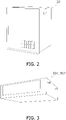
- the compressor unit 20 has external appearance depicted in FIG. 2 . As depicted in FIG. 1 , the compressor unit 20 is disposed inside the building B.
- the compressor unit 20 includes a case 20a, a first compressor 21, a first four-way switching valve 22, a first connecting port 23, a cascade heat exchanger 24, a second compressor 25, a second four-way switching valve 26, a compressor unit expansion valve 27, a second connecting port 28, a leakage detection sensor 61, and the compressor unit control unit 29.
- the compressor unit 20 handles the first refrigerant R1 and a second refrigerant R2.
- the case 20a accommodates components constituting the compressor unit 20.
- the case 20a is made of a metal or the like.
- the first compressor 21 compresses the first refrigerant R1 that is sucked and is in a low-pressure gas state to obtain the first refrigerant R1 in a high-pressure gas state.
- the first compressor 21 includes a first compressor motor 21a.
- the first compressor motor 21a generates motive power necessary for compression.
- the first compressor 21 is a vibration source and may thus cause refrigerant leakage from the first compressor 21 and a component adjacent thereto.
- the first four-way switching valve 22 switches connection of a refrigerant circuit. During cooling operation, the first four-way switching valve 22 achieves connection depicted by solid lines in FIG. 1 . During heating operation, the first four-way switching valve 22 achieves connection depicted by broken lines in FIG. 1 .
- the first connecting port 23 includes a pair of ports provided for connection of the first connection piping 30 to be described later.
- the first connecting port 23 is provided with a first liquid side shutoff valve 23a and a first gas side shutoff valve 23b.
- the first liquid side shutoff valve 23a and the first gas side shutoff valve 23b shut off a refrigerant flow path in response to a received command.
- the cascade heat exchanger 24 includes two refrigerant flow paths and exchanges heat between the first refrigerant R1 and the second refrigerant R2.
- the cascade heat exchanger 24 functions as a heat absorber (or an evaporator) for the first refrigerant R1, and as a heat radiator (or a condenser) for the second refrigerant R2.
- the cascade heat exchanger 24 functions as a heat radiator (or a condenser) for the first refrigerant R1, and as a heat absorber (or an evaporator) for the second refrigerant R2.
- the second compressor 25 compresses the second refrigerant R2 that is sucked and is in a low-pressure gas state to obtain the second refrigerant R2 in a high-pressure gas state.
- the second compressor 25 includes a second compressor motor 25a.
- the second compressor motor 25a generates motive power necessary for compression.
- the second compressor 25 is a vibration source and may thus cause refrigerant leakage from the second compressor 25 and a component adjacent thereto.
- the second four-way switching valve 26 switches connection of the refrigerant circuit. During cooling operation, the second four-way switching valve 26 achieves the connection depicted by the solid lines in FIG. 1 . During heating operation, the second four-way switching valve 26 achieves the connection depicted by the broken lines in FIG. 1 .
- the compressor unit expansion valve 27 decompresses the second refrigerant R2.
- the compressor unit expansion valve 27 is configured to adjust its opening degree.
- the second connecting port 28 includes a pair of ports provided for connection of the second connection piping 40 to be described later.
- the second connecting port 28 is provided with a second liquid side shutoff valve 28a and a second gas side shutoff valve 28b.
- the second liquid side shutoff valve 28a and the second gas side shutoff valve 28b shut off the refrigerant flow path in response to a received command.
- the leakage detection sensor 61 detects refrigerant leakage.
- the leakage detection sensor 61 is a refrigerant detection sensor 61a configured to detect presence of at least one of the first refrigerant R1 or the second refrigerant R2.
- the compressor unit control unit 29 includes a microcomputer and a memory.
- the compressor unit control unit 29 controls the first compressor motor 21a, the first four-way switching valve 22, the first liquid side shutoff valve 23a, the first gas side shutoff valve 23b, the second compressor motor 25a, the second four-way switching valve 26, the compressor unit expansion valve 27, the second liquid side shutoff valve 28a, the second gas side shutoff valve 28b, and the like.
- the compressor unit control unit 29 receives a signal from the leakage detection sensor 61.
- the memory stores software for control of these components.
- the compressor unit control unit 29 transmits and receives data and a command, via a communication line (not depicted), to and from each of the heat source heat exchanger unit control unit 19 and the utilization unit control unit 59 to be described later.
- the first connection piping 30 connects the heat source heat exchanger unit 10 and the compressor unit 20.
- the first connection piping 30 includes a first liquid connection pipe 31 and a first gas connection pipe 32.
- the first liquid connection pipe 31 connects the heat source heat exchanger unit 10 and the first liquid side shutoff valve 23a.
- the first liquid connection pipe 31 guides the first refrigerant R1 principally in a high-pressure liquid state or in a low-pressure gas-liquid two-phase state.
- the first gas connection pipe 32 connects the heat source heat exchanger unit 10 and the first gas side shutoff valve 23b.
- the first gas connection pipe 32 guides the first refrigerant R1 principally in the high-pressure gas state or in the low-pressure gas state.
- the utilization units 501 and 502 each have external appearance depicted in FIG. 3 . As depicted in FIG. 1 , the utilization units 501 and 502 are disposed inside the building B. The utilization units 501 and 502 handle the second refrigerant R2. The utilization unit 501 and the utilization unit 502 are configured identically to each other. The following description will thus be made to only the utilization unit 501 without repetitively describing the utilization unit 502.
- the utilization unit 501 includes a case 50a, a utilization unit expansion valve 51, a utilization heat exchanger 52, a utilization fan 53, and the utilization unit control unit 59.
- the case 50a accommodates components constituting the utilization unit 501.
- the utilization unit expansion valve 51 decompresses the second refrigerant R2.
- the utilization unit expansion valve 51 limits a flow rate of the second refrigerant R2.
- the utilization unit expansion valve 51 is configured to adjust its opening degree.
- the utilization heat exchanger 52 provides a user with low temperature heat or high temperature heat.
- the utilization heat exchanger 52 exchanges heat between air inside the building B and the second refrigerant R2.
- the utilization heat exchanger 52 functions as a heat absorber (or an evaporator) for the second refrigerant R2.
- the utilization heat exchanger 52 functions as a heat radiator (or a condenser) for the second refrigerant R2.
- the utilization fan 53 generates an air flow to promote heat exchange at the utilization heat exchanger 52.
- the utilization unit control unit 59 includes a microcomputer and a memory.
- the utilization unit control unit 59 controls the utilization unit expansion valve 51, the utilization fan 53, and the like.
- the memory stores software for control of these components.
- the utilization unit control unit 59 transmits and receives data and a command, via a communication line (not depicted), to and from each of the heat source heat exchanger unit control unit 19 and the compressor unit control unit 29.
- the second connection piping 40 connects the compressor unit 20 and the utilization units 501 and 502.
- the second connection piping 40 includes a second liquid connection pipe 41 and a second gas connection pipe 42.
- the second liquid connection pipe 41 connects the second liquid side shutoff valve 28a and the utilization units 501 and 502.
- the second liquid connection pipe 41 guides the second refrigerant R2 principally in a high-pressure liquid state or in a low-pressure gas-liquid two-phase state.
- the second gas connection pipe 42 connects the second gas side shutoff valve 28b and the utilization units 501 and 502.
- the second gas connection pipe 42 guides the second refrigerant R2 principally in the high-pressure gas state or in the low-pressure gas state.
- the refrigeration apparatus 100 entirely constitutes two refrigerant cycles.
- the first refrigerant cycle C1 causes circulation of the first refrigerant R1.
- the first refrigerant cycle C1 adopts the heat source heat exchanger 11 as a heat source.
- the first refrigerant cycle C1 is constituted by components such as the first compressor 21, the first four-way switching valve 22, the first gas side shutoff valve 23b, the heat source heat exchanger 11, the heat source heat exchanger unit expansion valve 13, the first liquid side shutoff valve 23a, and the cascade heat exchanger 24.
- the second refrigerant cycle C2 causes circulation of the second refrigerant R2.
- the second refrigerant cycle C2 adopts the cascade heat exchanger 24 as a heat source.
- the second refrigerant cycle C2 is constituted by components such as the second compressor 25, the second four-way switching valve 26, the cascade heat exchanger 24, the compressor unit expansion valve 27, the second liquid side shutoff valve 28a, the utilization unit expansion valve 51, the utilization heat exchanger 52, and the second gas side shutoff valve 28b.
- the first refrigerant R1 is R32 or carbon dioxide.
- the first refrigerant R1 can thus be reduced in global warming potential (GWP) valve. This leads to inhibition of global warming due to use of the refrigeration apparatus 100.
- GWP global warming potential
- the second refrigerant R2 is R32 or R410A.
- the second refrigerant R2 can thus be reduced in GWP valve. This leads to inhibition of global warming due to use of the refrigeration apparatus 100.
- Exemplarily adopting R32 or carbon dioxide as the first refrigerant R1 and R32 as the second refrigerant R2 inhibits global warming caused by the refrigeration apparatus 100.
- the first refrigerant R1 and the second refrigerant R2 are preferably natural refrigerants.
- the compressor unit control unit 29 shuts off the first liquid side shutoff valve 23a, the first gas side shutoff valve 23b, the second liquid side shutoff valve 28a, and the second gas side shutoff valve 28b. This inhibits the first refrigerant R1 and the second refrigerant R2 in the compressor unit 20 from flowing out of the compressor unit 20.
- the refrigerant circuit constituted by the compressor unit 20 is divided into the first refrigerant cycle C1 and the second refrigerant cycle C2. Both the first refrigerant R1 and the second refrigerant R2 are thus less likely to leak in a case where the refrigerant circuit has damage or the like, achieving reduction in volume of a leaking refrigerant.
- the compressor unit 20 and the heat source heat exchanger unit 10 are constituted as separate units.
- the refrigeration apparatus 100 accordingly includes the first connection piping 30 connecting the compressor unit 20 and the heat source heat exchanger unit 10.
- the refrigeration apparatus 100 including the first connection piping 30 having a large length uses a more refrigerant in comparison to a refrigeration apparatus including a compressor and a heat source heat exchanger belonging to an identical unit.
- the refrigeration apparatus 100 thus configured has two refrigerant cycles including the first refrigerant cycle C1 and the second refrigerant cycle C2 to inhibit spread of a leaking refrigerant.
- the compressor unit 20 includes the leakage detection sensor 61. This enables quick detection of refrigerant leakage in an exemplary case where a vibration source such as a compressor damages the refrigerant circuit.
- the leakage detection sensor 61 is the refrigerant detection sensor 61a. This enables direct detection of refrigerant leakage.
- the first refrigerant cycle C1 includes the first liquid side shutoff valve 23a and the first gas side shutoff valve 23b.
- the first liquid side shutoff valve 23a and the first gas side shutoff valve 23b are shut off upon detection of refrigerant leakage to inhibit a leaking refrigerant from reaching outside the compressor unit 20.
- the second refrigerant cycle C2 includes the second liquid side shutoff valve 28a and the second gas side shutoff valve 28b.
- the second liquid side shutoff valve 28a and the second gas side shutoff valve 28b are shut off upon detection of refrigerant leakage to inhibit a leaking refrigerant from reaching outside the compressor unit 20.
- the compressor unit control unit 29 Upon detection of refrigerant leakage, the compressor unit control unit 29 automatically closes the first liquid side shutoff valve 23a and the first gas side shutoff valve 23b. This enables quick shutoff of the refrigerant circuit.
- This configuration can also confine the first refrigerant R1 within the first connection piping 30 and the heat source heat exchange unit 10.
- FIG. 4 depicts the refrigeration apparatus 100 according to the modification example 1A of the first embodiment. Unlike the above embodiment, the refrigeration apparatus 100 includes neither the second liquid side shutoff valve 28a nor the second gas side shutoff valve 28b at the second connecting port 28.
- the first liquid side shutoff valve 23a and the first gas side shutoff valve 23b are shut off upon detection of refrigerant leakage to inhibit refrigerant leakage.
- the second refrigerant R2 used in the second refrigerant cycle C2 is preferably an incombustible refrigerant such as R410 in this configuration. Adopting such an incombustible refrigerant in the second refrigerant cycle C2 including the utilization units 501 and 502 secures safety of the user even in a case where the second refrigerant R2 leaks in the second refrigerant cycle C2.
- FIG. 5 depicts the refrigeration apparatus 100 according to the modification example 1B of the first embodiment.
- the compressor unit 20 includes a decompression valve 62 and a subcooling heat exchanger 63.
- the decompression valve 62 and the subcooling heat exchanger 63 belong to the second refrigerant cycle C2.
- the subcooling heat exchanger 63 includes a first refrigerant flow path 63a and a second refrigerant flow path 63b.
- the decompression valve 62 decompresses the second refrigerant R2 to obtain the second refrigerant R2 in a low-temperature gas state.
- the second refrigerant R2 in the low-temperature gas state passes through the second refrigerant flow path 63b.
- the second refrigerant R2 passing through the first refrigerant flow path 63a is cooled by the second refrigerant R2 passing through the second refrigerant flow path 63b to acquire a degree of subcooling.
- the second refrigerant R2 flowing out of the second refrigerant flow path 63b is sucked into a suction pipe of the second compressor 25.
- the second refrigerant cycle C2 in this configuration includes the subcooling heat exchanger 63. This configuration is thus likely to secure subcooling in the utilization units 501 and 502.
- the second refrigerant R2 in this configuration partially passes through the second refrigerant flow path 63b serving as a bypass route. Even in a case where the second connection piping 40 (the second liquid connection pipe 41 and the second gas connection pipe 42) in the second refrigerant cycle C2 has a large length, the second refrigerant R2 flowing in the second connection piping 40 is reduced in volume to achieve reduction in pressure loss of the second refrigerant R2 as well as secure subcooling.
- the second refrigerant R2 flowing out of the second refrigerant flow path 63b may alternatively be intermediately injected, i.e., be injected directly to a compression chamber of the second compressor 25, instead of being sucked into the suction pipe of the second compressor 25.
- FIG. 6 depicts the refrigeration apparatus 100 according to the modification example 1C of the first embodiment.
- the compressor unit 20 includes the subcooling heat exchanger 63.
- the subcooling heat exchanger 63 belongs to the second refrigerant cycle C2.
- the subcooling heat exchanger 63 includes a first refrigerant flow path 63a and a second refrigerant flow path 63b.
- the second refrigerant cycle C2 in this configuration includes the subcooling heat exchanger 63. This configuration is thus likely to secure subcooling in the utilization units 501 and 502.
- the second refrigerant R2 flowing in the second connection piping 40 (the second liquid connection pipe 41 and the second gas connection pipe 42) can be reduced in pressure loss while the compressor 25 can be reduced in electric power consumption.
- FIG. 7 depicts the refrigeration apparatus 100 according to the modification example 1D of the first embodiment.
- the compressor unit 20 includes refrigerant jackets 651 and 652.
- the refrigerant jackets 651 and 652 thermally couple circuit boards constituting compressor unit control units 291 and 292, and cooling pipes 641 and 642, respectively.
- the cooling pipes 641 and 642 each guide a liquid refrigerant.
- the circuit boards constituting the compressor unit control units 291 and 292 are thus cooled by the cooling pipes 641 and 642, respectively.
- the compressor unit control units 291 and 292 are cooled by the cooling pipes 641 and 642, respectively. This achieves effective cooling of the compressor unit control units 291 and 292 that generate heat.
- FIG. 8 depicts the refrigeration apparatus 100 according to the modification example 1E of the first embodiment.
- the circuit board constituting the compressor unit control unit 29 is disposed outside the case 20a. This enables effective release of heat generated by the compressor unit control unit 29.
- the heat source heat exchanger unit 10 is disposed outside the building B.
- the heat source heat exchanger unit 10 may alternatively be disposed inside the building B and be fluid connected to an outside of the building B.
- the heat source heat exchanger unit 10 may be disposed at a duct provided to the building B and allowing passage of outdoor air.
- the heat source heat exchanger unit 10 in this configuration is invisible from outside the building B.
- the refrigeration apparatus 100 thus does not affect quality in outer appearance of the building B.
- the above embodiment employs two utilization units, namely, the utilization units 501 and 502.
- the number of the utilization units may alternatively be other than two.
- the number of the utilization units may be one, three, or four.
- the heat source heat exchanger 11 mounted to the heat source heat exchanger unit 10 according to the above embodiment is configured to exchange heat between the first refrigerant R1 and air.
- the heat source heat exchanger 11 may alternatively be configured to exchange heat between the first refrigerant R1 and water.
- the heat source heat exchanger 11 may still alternatively be configured to exchange heat between the first refrigerant R1 and brine.
- the heat source heat exchanger 11 is connected to the first refrigerant cycle C1 as well as to a cooling tower or the like.
- the utilization heat exchanger 52 mounted to each of the utilization units 501 and 502 is configured to exchange heat between the second refrigerant R2 and air.
- the utilization heat exchanger 52 may alternatively be configured to exchange heat between the second refrigerant R2 and water. This configuration achieves provision of hot water to the user.
- the utilization heat exchanger 52 may still alternatively be configured to exchange heat between the second refrigerant R2 and brine.
- the utilization heat exchanger 52 is connected to the second refrigerant cycle C2 as well as to a heat radiator or the like.
- the heat radiator provides the user with heat energy carried by the brine.
- FIG. 10 is a circuit diagram of a refrigeration apparatus 100 according to the second embodiment.
- the leakage detection sensor 61 is a pressure sensor 61b.
- the pressure sensor 61b detects pressure in the case 20a.
- the case 20a has airtightness.
- the case 20a further includes a rupture disk 66. The rupture disk 66 is destroyed by pressure exceeding a predetermined value.
- the case 20a has airtightness. This inhibits a refrigerant leaking in the case 20a from reaching outside the case 20a.
- the leakage detection sensor 61 is the pressure sensor 61b.
- refrigerant leakage can be detected in accordance with pressure change.
- the case 20a includes the rupture disk 66.
- the rupture disk 66 is thus destroyed to release abnormally increased pressure in the case 20a.
- the case 20a has airtightness.
- the compressor unit 20 thus has higher sound insulation. This is particularly useful when the compressor unit 20 is disposed inside the building B.
- the case 20a has airtightness.
- the case 20a thus achieves a higher electromagnetic noise cutoff effect when the case 20a is made of a metal.
- the above embodiment does not refer to cooling of the circuit board constituting the compressor unit control unit 29.
- the case 20a of the compressor unit 20 has airtightness, so that the case 20a is likely to contain heat generated by the circuit board.
- the circuit board in this configuration is cooled to inhibit containment of heat in the case 20a.
- the circuit board constituting the compressor unit control unit 29 according to the above embodiment is disposed inside the case 20a.
- the case 20a of the compressor unit 20 has airtightness, so that the case 20a is likely to contain heat generated by the circuit board.
- the circuit board may alternatively be disposed outside the case 20a.
- This configuration can inhibit containment of heat in the case 20a.
- Patent Literature 1 Japanese Patent Application Laid-Open Publication No. 2018- 511771
Landscapes
- Engineering & Computer Science (AREA)
- Mechanical Engineering (AREA)
- General Engineering & Computer Science (AREA)
- Physics & Mathematics (AREA)
- Thermal Sciences (AREA)
- Chemical & Material Sciences (AREA)
- Combustion & Propulsion (AREA)
- Air Conditioning Control Device (AREA)
- Other Air-Conditioning Systems (AREA)
- Compression-Type Refrigeration Machines With Reversible Cycles (AREA)
- Devices That Are Associated With Refrigeration Equipment (AREA)
Abstract
Description
- The present disclosure relates to a compressor unit and a refrigeration apparatus including the compressor unit.
- Patent Literature 1 (
Japanese Patent Application Laid-Open Publication No. 2018- 511771 - When an air conditioner has damage at a pipe or the like constituting a refrigerant circuit, refrigerant leakage might occur from the refrigerant circuit. The air conditioner disclosed in Patent Literature 1 includes a refrigerant circuit constituted by a single refrigerant cycle circuit, and therefore the entire refrigerant may leak from the refrigerant circuit. Accordingly requested is reduction in volume of a leaking refrigerant.
- A compressor unit according to a first aspect includes a first case, a first compressor accommodated in the first case, a cascade heat exchanger accommodated in the first case, a second compressor accommodated in the first case, a first connecting port, and a second connecting port. The first compressor, the cascade heat exchanger, and a heat source heat exchanger accommodated in a second case provided separately from the first case constitute a first refrigerant cycle. The first refrigerant cycle adopts the heat source heat exchanger as a heat source and causes circulation of a first refrigerant. The second compressor, the cascade heat exchanger, and a utilization heat exchanger accommodated in a third case provided separately from the first case constitute a second refrigerant cycle. The second refrigerant cycle adopts the cascade heat exchanger as a heat source and causes circulation of a second refrigerant. The cascade heat exchanger executes heat exchange between the first refrigerant and the second refrigerant. The first connecting port is connected to the heat source heat exchanger via a first connection pipe. The second connecting port is connected to the utilization heat exchanger via a second connection pipe.
- This configuration divides a refrigerant circuit constituted by the compressor unit into the first refrigerant cycle and the second refrigerant cycle. Both the first refrigerant and the second refrigerant are thus less likely to leak in a case where the refrigerant circuit has damage or the like, achieving reduction in volume of a leaking refrigerant.
- A compressor unit according to a second aspect is the compressor unit according to the first aspect, and further includes a subcooling heat exchanger accommodated in the first case. The subcooling heat exchanger belongs to the second refrigerant cycle.
- The second refrigerant cycle in this configuration includes the subcooling heat exchanger. This configuration is thus likely to secure subcooling in a utilization unit.
- A compressor unit according to a third aspect is the compressor unit according to the first or second aspect, and further includes a leakage detection sensor. The leakage detection sensor is accommodated in the first case and detects leakage of at least one of the first refrigerant or the second refrigerant.
- The compressor unit according to this configuration includes the leakage detection sensor. This enables quick detection of refrigerant leakage in an exemplary case where a vibration source such as a compressor damages the refrigerant circuit.
- A compressor unit according to a fourth aspect is the compressor unit according to the third aspect, and further includes a first shutoff valve. The first shutoff valve shuts off shift of the first refrigerant between the first connecting port and the heat source heat exchanger.
- The first refrigerant cycle in this configuration includes the first shutoff valve. The first shutoff valve is shut off upon detection of refrigerant leakage, to inhibit a leaking refrigerant from reaching outside the compressor unit.
- A compressor unit according to a fifth aspect is the compressor unit according to the fourth aspect, and further includes a control unit. The control unit closes the first shutoff valve when the leakage detection sensor detects leakage.
- The control unit in this configuration automatically closes the first shutoff valve upon detection of refrigerant leakage. This enables quick shutoff of the refrigerant circuit.
- A compressor unit according to a sixth aspect is the compressor unit according to the fifth aspect, in which the control unit is disposed outside the first case.
- The control unit is disposed outside the first case in this configuration. This enables effective release of heat generated by the control unit.
- A compressor unit according to a seventh aspect is the compressor unit according to the fifth aspect, and further includes a cooling refrigerant pipe accommodated in the first case. The control unit is disposed inside the first case and is cooled by the cooling refrigerant pipe.
- The control unit is cooled by the cooling refrigerant pipe in this configuration. This achieves effective cooling of the control unit that generates heat.
- A compressor unit according to an eighth aspect is the compressor unit according to any one of the third to seventh aspects, in which the leakage detection sensor is a refrigerant detection sensor. The refrigerant detection sensor detects presence of at least one of the first refrigerant or the second refrigerant.
- The leakage detection sensor is the refrigerant detection sensor in this configuration. This enables direct detection of refrigerant leakage.
- A compressor unit according to a ninth aspect is the compressor unit according to any one of the third to seventh aspects, in which the first case has airtightness.
- The first case has airtightness in this configuration. This inhibits a refrigerant leaking in the first case from reaching outside the first case.
- A compressor unit according to a tenth aspect is the compressor unit according to the ninth aspect, in which the leakage detection sensor is a pressure sensor. The pressure sensor detects pressure in the first case.
- The leakage detection sensor is the pressure sensor in this configuration. When a refrigerant leaks in the first case having airtightness, refrigerant leakage can be detected in accordance with pressure change.
- A compressor unit according to an eleventh aspect is the compressor unit according to the ninth or tenth aspect, in which the first case includes a rupture disk. The rupture disk is destroyed by pressure exceeding a predetermined value.
- The first case in this configuration includes the rupture disk. The rupture disk is thus destroyed to release abnormally increased pressure in the first case.
- A compressor unit according to a twelfth aspect is the compressor unit according to any one of the first to tenth aspects, in which the first refrigerant is R32 or carbon dioxide. The second refrigerant is R32 or R410A.
- The first refrigerant and the second refrigerant are natural refrigerants in this configuration.
- A refrigeration apparatus according to a thirteenth aspect includes a compressor unit, a heat source heat exchanger unit, and a utilization unit. The compressor unit is according to any one of the first to eleventh aspects. The heat source heat exchanger unit includes the second case and the heat source heat exchanger. The utilization unit includes the third case and the utilization heat exchanger.
- This configuration divides the refrigerant circuit constituted by the refrigeration apparatus into the first refrigerant cycle and the second refrigerant cycle. Both the first refrigerant and the second refrigerant are thus less likely to leak in a case where the refrigerant circuit has damage or the like, achieving reduction in volume of a leaking refrigerant.
- A refrigeration apparatus according to a fourteenth aspect is the refrigeration apparatus according to the thirteenth aspect, in which the compressor unit is disposed inside a building. The heat source heat exchanger unit is disposed inside the building and is fluid connected to an outside of the building.
- The heat source heat exchanger unit in this configuration is invisible from outside the building. The refrigeration apparatus thus does not affect quality in outer appearance of the building.
- A refrigeration apparatus according to a fifteenth aspect is the refrigeration apparatus according to the thirteenth or fourteenth aspect, in which the heat source heat exchanger unit includes a first main expansion valve. The first main expansion valve belongs to the first refrigerant cycle and is accommodated in the second case. The compressor unit includes a second main expansion valve. The second main expansion valve belongs to the second refrigerant cycle and is accommodated in the first case.
- In this configuration, each refrigerant pipe in the first refrigerant cycle and the second refrigerant cycle has a flow of a liquid refrigerant during heating operation. This reduces pressure loss of a refrigerant flow in each connection pipe.
-
-
FIG. 1 is a circuit diagram of arefrigeration apparatus 100 according to a first embodiment. -
FIG. 2 is an external view of acompressor unit 20. -
FIG. 3 is an external view ofindoor units -
FIG. 4 is a circuit diagram of therefrigeration apparatus 100 according to a modification example 1A of the first embodiment. -
FIG. 5 is a circuit diagram of therefrigeration apparatus 100 according to a modification example 1B of the first embodiment. -
FIG. 6 is a circuit diagram of therefrigeration apparatus 100 according to a modification example 1C of the first embodiment. -
FIG. 7 is a circuit diagram of therefrigeration apparatus 100 according to a modification example 1D of the first embodiment. -
FIG. 8 is a circuit diagram of therefrigeration apparatus 100 according to a modification example 1E of the first embodiment. -
FIG. 9 is a schematic view of therefrigeration apparatus 100 according to a modification example IF of the first embodiment. -
FIG. 10 is a circuit diagram of arefrigeration apparatus 100 according to a second embodiment. -
FIG. 1 is a circuit diagram of arefrigeration apparatus 100 according to the first embodiment. Therefrigeration apparatus 100 is typically exemplified by an air conditioner, but is not limited thereto. For example, therefrigeration apparatus 100 may be a refrigerator, a freezer, and a hot water supplier. Therefrigeration apparatus 100 includes a heat sourceheat exchanger unit 10, acompressor unit 20, a first connection piping 30,utilization units - The heat source
heat exchanger unit 10 is disposed outside a building B. The heat sourceheat exchanger unit 10 includes acase 10a, a heat source heat exchanger 11, aheat source fan 12, a heat source heat exchanger unit expansion valve 13, and a heat source heat exchangerunit control unit 19. The heat sourceheat exchanger unit 10 handles a first refrigerant R1. - The
case 10a accommodates components constituting the heat sourceheat exchanger unit 10. Thecase 10a is made of a metal or the like. - The heat source heat exchanger 11 functions as a heat source. The heat source heat exchanger 11 exchanges heat between air outside the building B and the first refrigerant R1. During cooling operation, the heat source heat exchanger 11 functions as a heat radiator (or a condenser) for the first refrigerant R1. During heating operation, the heat source heat exchanger 11 functions as a heat absorber (or an evaporator) for the first refrigerant R1.
- The
heat source fan 12 generates an air flow to promote heat exchange at the heat source heat exchanger 11. - The heat source heat exchanger unit expansion valve 13 decompresses the first refrigerant R1. The heat source heat exchanger unit expansion valve 13 is configured to adjust its opening degree.
- The heat source heat exchanger
unit control unit 19 includes a microcomputer and a memory. The heat source heat exchangerunit control unit 19 controls theheat source fan 12, the heat source heat exchanger unit expansion valve 13, and the like. The memory stores software for control of these components. - The heat source heat exchanger
unit control unit 19 transmits and receives data and a command, via a communication line (not depicted), to and from each of a compressorunit control unit 29 and a utilizationunit control unit 59, which will be described later. - The
compressor unit 20 has external appearance depicted inFIG. 2 . As depicted inFIG. 1 , thecompressor unit 20 is disposed inside the building B. Thecompressor unit 20 includes acase 20a, afirst compressor 21, a first four-way switching valve 22, a first connectingport 23, acascade heat exchanger 24, asecond compressor 25, a second four-way switching valve 26, a compressorunit expansion valve 27, a second connectingport 28, aleakage detection sensor 61, and the compressorunit control unit 29. Thecompressor unit 20 handles the first refrigerant R1 and a second refrigerant R2. - The
case 20a accommodates components constituting thecompressor unit 20. Thecase 20a is made of a metal or the like. - The
first compressor 21 compresses the first refrigerant R1 that is sucked and is in a low-pressure gas state to obtain the first refrigerant R1 in a high-pressure gas state. Thefirst compressor 21 includes afirst compressor motor 21a. Thefirst compressor motor 21a generates motive power necessary for compression. - The
first compressor 21 is a vibration source and may thus cause refrigerant leakage from thefirst compressor 21 and a component adjacent thereto. - The first four-
way switching valve 22 switches connection of a refrigerant circuit. During cooling operation, the first four-way switching valve 22 achieves connection depicted by solid lines inFIG. 1 . During heating operation, the first four-way switching valve 22 achieves connection depicted by broken lines inFIG. 1 . - The first connecting
port 23 includes a pair of ports provided for connection of the first connection piping 30 to be described later. The first connectingport 23 is provided with a first liquidside shutoff valve 23a and a first gasside shutoff valve 23b. The first liquidside shutoff valve 23a and the first gasside shutoff valve 23b shut off a refrigerant flow path in response to a received command. - The
cascade heat exchanger 24 includes two refrigerant flow paths and exchanges heat between the first refrigerant R1 and the second refrigerant R2. During cooling operation, thecascade heat exchanger 24 functions as a heat absorber (or an evaporator) for the first refrigerant R1, and as a heat radiator (or a condenser) for the second refrigerant R2. During heating operation, thecascade heat exchanger 24 functions as a heat radiator (or a condenser) for the first refrigerant R1, and as a heat absorber (or an evaporator) for the second refrigerant R2. - The
second compressor 25 compresses the second refrigerant R2 that is sucked and is in a low-pressure gas state to obtain the second refrigerant R2 in a high-pressure gas state. Thesecond compressor 25 includes asecond compressor motor 25a. Thesecond compressor motor 25a generates motive power necessary for compression. - The
second compressor 25 is a vibration source and may thus cause refrigerant leakage from thesecond compressor 25 and a component adjacent thereto. - The second four-
way switching valve 26 switches connection of the refrigerant circuit. During cooling operation, the second four-way switching valve 26 achieves the connection depicted by the solid lines inFIG. 1 . During heating operation, the second four-way switching valve 26 achieves the connection depicted by the broken lines inFIG. 1 . - The compressor
unit expansion valve 27 decompresses the second refrigerant R2. The compressorunit expansion valve 27 is configured to adjust its opening degree. - The second connecting
port 28 includes a pair of ports provided for connection of the second connection piping 40 to be described later. The second connectingport 28 is provided with a second liquidside shutoff valve 28a and a second gasside shutoff valve 28b. The second liquidside shutoff valve 28a and the second gasside shutoff valve 28b shut off the refrigerant flow path in response to a received command. - The
leakage detection sensor 61 detects refrigerant leakage. Theleakage detection sensor 61 is arefrigerant detection sensor 61a configured to detect presence of at least one of the first refrigerant R1 or the second refrigerant R2. - The compressor
unit control unit 29 includes a microcomputer and a memory. The compressorunit control unit 29 controls thefirst compressor motor 21a, the first four-way switching valve 22, the first liquidside shutoff valve 23a, the first gasside shutoff valve 23b, thesecond compressor motor 25a, the second four-way switching valve 26, the compressorunit expansion valve 27, the second liquidside shutoff valve 28a, the second gasside shutoff valve 28b, and the like. The compressorunit control unit 29 receives a signal from theleakage detection sensor 61. The memory stores software for control of these components. - The compressor
unit control unit 29 transmits and receives data and a command, via a communication line (not depicted), to and from each of the heat source heat exchangerunit control unit 19 and the utilizationunit control unit 59 to be described later. - The first connection piping 30 connects the heat source
heat exchanger unit 10 and thecompressor unit 20. The first connection piping 30 includes a firstliquid connection pipe 31 and a firstgas connection pipe 32. - The first
liquid connection pipe 31 connects the heat sourceheat exchanger unit 10 and the first liquidside shutoff valve 23a. The firstliquid connection pipe 31 guides the first refrigerant R1 principally in a high-pressure liquid state or in a low-pressure gas-liquid two-phase state. - The first
gas connection pipe 32 connects the heat sourceheat exchanger unit 10 and the first gasside shutoff valve 23b. The firstgas connection pipe 32 guides the first refrigerant R1 principally in the high-pressure gas state or in the low-pressure gas state. - The
utilization units FIG. 3 . As depicted inFIG. 1 , theutilization units utilization units utilization unit 501 and theutilization unit 502 are configured identically to each other. The following description will thus be made to only theutilization unit 501 without repetitively describing theutilization unit 502. Theutilization unit 501 includes acase 50a, a utilizationunit expansion valve 51, autilization heat exchanger 52, autilization fan 53, and the utilizationunit control unit 59. - The
case 50a accommodates components constituting theutilization unit 501. - The utilization
unit expansion valve 51 decompresses the second refrigerant R2. The utilizationunit expansion valve 51 limits a flow rate of the second refrigerant R2. The utilizationunit expansion valve 51 is configured to adjust its opening degree. - The
utilization heat exchanger 52 provides a user with low temperature heat or high temperature heat. Theutilization heat exchanger 52 exchanges heat between air inside the building B and the second refrigerant R2. During cooling operation, theutilization heat exchanger 52 functions as a heat absorber (or an evaporator) for the second refrigerant R2. During heating operation, theutilization heat exchanger 52 functions as a heat radiator (or a condenser) for the second refrigerant R2. - The
utilization fan 53 generates an air flow to promote heat exchange at theutilization heat exchanger 52. - The utilization
unit control unit 59 includes a microcomputer and a memory. The utilizationunit control unit 59 controls the utilizationunit expansion valve 51, theutilization fan 53, and the like. The memory stores software for control of these components. - The utilization
unit control unit 59 transmits and receives data and a command, via a communication line (not depicted), to and from each of the heat source heat exchangerunit control unit 19 and the compressorunit control unit 29. - The second connection piping 40 connects the
compressor unit 20 and theutilization units liquid connection pipe 41 and a secondgas connection pipe 42. - The second
liquid connection pipe 41 connects the second liquidside shutoff valve 28a and theutilization units liquid connection pipe 41 guides the second refrigerant R2 principally in a high-pressure liquid state or in a low-pressure gas-liquid two-phase state. - The second
gas connection pipe 42 connects the second gasside shutoff valve 28b and theutilization units gas connection pipe 42 guides the second refrigerant R2 principally in the high-pressure gas state or in the low-pressure gas state. - The
refrigeration apparatus 100 entirely constitutes two refrigerant cycles. - The first refrigerant cycle C1 causes circulation of the first refrigerant R1. The first refrigerant cycle C1 adopts the heat source heat exchanger 11 as a heat source. The first refrigerant cycle C1 is constituted by components such as the
first compressor 21, the first four-way switching valve 22, the first gasside shutoff valve 23b, the heat source heat exchanger 11, the heat source heat exchanger unit expansion valve 13, the first liquidside shutoff valve 23a, and thecascade heat exchanger 24. - The second refrigerant cycle C2 causes circulation of the second refrigerant R2. The second refrigerant cycle C2 adopts the
cascade heat exchanger 24 as a heat source. The second refrigerant cycle C2 is constituted by components such as thesecond compressor 25, the second four-way switching valve 26, thecascade heat exchanger 24, the compressorunit expansion valve 27, the second liquidside shutoff valve 28a, the utilizationunit expansion valve 51, theutilization heat exchanger 52, and the second gasside shutoff valve 28b. - The first refrigerant R1 is R32 or carbon dioxide. The first refrigerant R1 can thus be reduced in global warming potential (GWP) valve. This leads to inhibition of global warming due to use of the
refrigeration apparatus 100. - The second refrigerant R2 is R32 or R410A. The second refrigerant R2 can thus be reduced in GWP valve. This leads to inhibition of global warming due to use of the
refrigeration apparatus 100. - Exemplarily adopting R32 or carbon dioxide as the first refrigerant R1 and R32 as the second refrigerant R2 inhibits global warming caused by the
refrigeration apparatus 100. - The first refrigerant R1 and the second refrigerant R2 are preferably natural refrigerants.
- When the
leakage detection sensor 61 detects refrigerant leakage, the compressorunit control unit 29 shuts off the first liquidside shutoff valve 23a, the first gasside shutoff valve 23b, the second liquidside shutoff valve 28a, and the second gasside shutoff valve 28b. This inhibits the first refrigerant R1 and the second refrigerant R2 in thecompressor unit 20 from flowing out of thecompressor unit 20. - (5-1) The refrigerant circuit constituted by the
compressor unit 20 is divided into the first refrigerant cycle C1 and the second refrigerant cycle C2. Both the first refrigerant R1 and the second refrigerant R2 are thus less likely to leak in a case where the refrigerant circuit has damage or the like, achieving reduction in volume of a leaking refrigerant. - The
compressor unit 20 and the heat sourceheat exchanger unit 10 are constituted as separate units. Therefrigeration apparatus 100 accordingly includes the first connection piping 30 connecting thecompressor unit 20 and the heat sourceheat exchanger unit 10. Therefrigeration apparatus 100 including the first connection piping 30 having a large length uses a more refrigerant in comparison to a refrigeration apparatus including a compressor and a heat source heat exchanger belonging to an identical unit. However, therefrigeration apparatus 100 thus configured has two refrigerant cycles including the first refrigerant cycle C1 and the second refrigerant cycle C2 to inhibit spread of a leaking refrigerant. - (5-2) The
compressor unit 20 includes theleakage detection sensor 61. This enables quick detection of refrigerant leakage in an exemplary case where a vibration source such as a compressor damages the refrigerant circuit. - The
leakage detection sensor 61 is therefrigerant detection sensor 61a. This enables direct detection of refrigerant leakage. - (5-3) The first refrigerant cycle C1 includes the first liquid
side shutoff valve 23a and the first gasside shutoff valve 23b. The first liquidside shutoff valve 23a and the first gasside shutoff valve 23b are shut off upon detection of refrigerant leakage to inhibit a leaking refrigerant from reaching outside thecompressor unit 20. - The second refrigerant cycle C2 includes the second liquid
side shutoff valve 28a and the second gasside shutoff valve 28b. The second liquidside shutoff valve 28a and the second gasside shutoff valve 28b are shut off upon detection of refrigerant leakage to inhibit a leaking refrigerant from reaching outside thecompressor unit 20. - (5-4) Upon detection of refrigerant leakage, the compressor
unit control unit 29 automatically closes the first liquidside shutoff valve 23a and the first gasside shutoff valve 23b. This enables quick shutoff of the refrigerant circuit. - This configuration can also confine the first refrigerant R1 within the first connection piping 30 and the heat source
heat exchange unit 10. - (5-5) During heating operation, a liquid refrigerant flows in each of the first
liquid connection pipe 31 in the first refrigerant cycle C1 and the secondliquid connection pipe 41 in the second refrigerant cycle C2. This reduces pressure loss of a refrigerant flow in each of the firstliquid connection pipe 31 and the secondliquid connection pipe 41. -
FIG. 4 depicts therefrigeration apparatus 100 according to the modification example 1A of the first embodiment. Unlike the above embodiment, therefrigeration apparatus 100 includes neither the second liquidside shutoff valve 28a nor the second gasside shutoff valve 28b at the second connectingport 28. - Also in this configuration, the first liquid
side shutoff valve 23a and the first gasside shutoff valve 23b are shut off upon detection of refrigerant leakage to inhibit refrigerant leakage. - The second refrigerant R2 used in the second refrigerant cycle C2 is preferably an incombustible refrigerant such as R410 in this configuration. Adopting such an incombustible refrigerant in the second refrigerant cycle C2 including the
utilization units - Furthermore, adopting R32 or carbon dioxide as the first refrigerant R1 used in the first refrigerant cycle C1 inhibits global warming caused by the
refrigeration apparatus 100. -
FIG. 5 depicts therefrigeration apparatus 100 according to the modification example 1B of the first embodiment. Unlike the above embodiment, thecompressor unit 20 includes adecompression valve 62 and asubcooling heat exchanger 63. Thedecompression valve 62 and thesubcooling heat exchanger 63 belong to the second refrigerant cycle C2. Thesubcooling heat exchanger 63 includes a firstrefrigerant flow path 63a and a secondrefrigerant flow path 63b. - The
decompression valve 62 decompresses the second refrigerant R2 to obtain the second refrigerant R2 in a low-temperature gas state. The second refrigerant R2 in the low-temperature gas state passes through the secondrefrigerant flow path 63b. The second refrigerant R2 passing through the firstrefrigerant flow path 63a is cooled by the second refrigerant R2 passing through the secondrefrigerant flow path 63b to acquire a degree of subcooling. The second refrigerant R2 flowing out of the secondrefrigerant flow path 63b is sucked into a suction pipe of thesecond compressor 25. - The second refrigerant cycle C2 in this configuration includes the
subcooling heat exchanger 63. This configuration is thus likely to secure subcooling in theutilization units - Furthermore, the second refrigerant R2 in this configuration partially passes through the second
refrigerant flow path 63b serving as a bypass route. Even in a case where the second connection piping 40 (the secondliquid connection pipe 41 and the second gas connection pipe 42) in the second refrigerant cycle C2 has a large length, the second refrigerant R2 flowing in the second connection piping 40 is reduced in volume to achieve reduction in pressure loss of the second refrigerant R2 as well as secure subcooling. - The second refrigerant R2 flowing out of the second
refrigerant flow path 63b may alternatively be intermediately injected, i.e., be injected directly to a compression chamber of thesecond compressor 25, instead of being sucked into the suction pipe of thesecond compressor 25. -
FIG. 6 depicts therefrigeration apparatus 100 according to the modification example 1C of the first embodiment. Unlike the above embodiment, thecompressor unit 20 includes thesubcooling heat exchanger 63. Thesubcooling heat exchanger 63 belongs to the second refrigerant cycle C2. Thesubcooling heat exchanger 63 includes a firstrefrigerant flow path 63a and a secondrefrigerant flow path 63b. - The second refrigerant cycle C2 in this configuration includes the
subcooling heat exchanger 63. This configuration is thus likely to secure subcooling in theutilization units - This secures the degree of subcooling even in a case where the second refrigerant R2 has less circulation volume. In this case, the second refrigerant R2 flowing in the second connection piping 40 (the second
liquid connection pipe 41 and the second gas connection pipe 42) can be reduced in pressure loss while thecompressor 25 can be reduced in electric power consumption. -
FIG. 7 depicts therefrigeration apparatus 100 according to the modification example 1D of the first embodiment. Unlike the above embodiment, thecompressor unit 20 includesrefrigerant jackets 651 and 652. Therefrigerant jackets 651 and 652 thermally couple circuit boards constituting compressorunit control units 291 and 292, and coolingpipes pipes unit control units 291 and 292 are thus cooled by the coolingpipes - In this configuration, the compressor
unit control units 291 and 292 are cooled by the coolingpipes unit control units 291 and 292 that generate heat. -
FIG. 8 depicts therefrigeration apparatus 100 according to the modification example 1E of the first embodiment. In thisrefrigeration apparatus 100, unlike the above embodiment, the circuit board constituting the compressorunit control unit 29 is disposed outside thecase 20a. This enables effective release of heat generated by the compressorunit control unit 29. - The heat source
heat exchanger unit 10 according to the above embodiment is disposed outside the building B. The heat sourceheat exchanger unit 10 may alternatively be disposed inside the building B and be fluid connected to an outside of the building B. As exemplarily depicted inFIG. 9 , the heat sourceheat exchanger unit 10 may be disposed at a duct provided to the building B and allowing passage of outdoor air. - The heat source
heat exchanger unit 10 in this configuration is invisible from outside the building B. Therefrigeration apparatus 100 thus does not affect quality in outer appearance of the building B. - The above embodiment employs two utilization units, namely, the
utilization units - The heat source heat exchanger 11 mounted to the heat source
heat exchanger unit 10 according to the above embodiment is configured to exchange heat between the first refrigerant R1 and air. The heat source heat exchanger 11 may alternatively be configured to exchange heat between the first refrigerant R1 and water. The heat source heat exchanger 11 may still alternatively be configured to exchange heat between the first refrigerant R1 and brine. In this case, the heat source heat exchanger 11 is connected to the first refrigerant cycle C1 as well as to a cooling tower or the like. - The
utilization heat exchanger 52 mounted to each of theutilization units utilization heat exchanger 52 may alternatively be configured to exchange heat between the second refrigerant R2 and water. This configuration achieves provision of hot water to the user. Theutilization heat exchanger 52 may still alternatively be configured to exchange heat between the second refrigerant R2 and brine. In this case, theutilization heat exchanger 52 is connected to the second refrigerant cycle C2 as well as to a heat radiator or the like. The heat radiator provides the user with heat energy carried by the brine. -
FIG. 10 is a circuit diagram of arefrigeration apparatus 100 according to the second embodiment. In thisrefrigeration apparatus 100, unlike the first embodiment, the leakage detection sensor 61is apressure sensor 61b. Thepressure sensor 61b detects pressure in thecase 20a. Thecase 20a has airtightness. Thecase 20a further includes arupture disk 66. Therupture disk 66 is destroyed by pressure exceeding a predetermined value. - (2-1) The
case 20a has airtightness. This inhibits a refrigerant leaking in thecase 20a from reaching outside thecase 20a. - (2-2) The
leakage detection sensor 61 is thepressure sensor 61b. When a refrigerant leaks in thecase 20a having airtightness, refrigerant leakage can be detected in accordance with pressure change. - (2-3) The
case 20a includes therupture disk 66. Therupture disk 66 is thus destroyed to release abnormally increased pressure in thecase 20a. - (2-4) The
case 20a has airtightness. Thecompressor unit 20 thus has higher sound insulation. This is particularly useful when thecompressor unit 20 is disposed inside the building B. - (2-5) The
case 20a has airtightness. Thecase 20a thus achieves a higher electromagnetic noise cutoff effect when thecase 20a is made of a metal. - The above embodiment does not refer to cooling of the circuit board constituting the compressor
unit control unit 29. Thecase 20a of thecompressor unit 20 has airtightness, so that thecase 20a is likely to contain heat generated by the circuit board. As in the modification example ID, there may be provided the refrigerant jacket thermally connecting the circuit board and the cooling pipe. - The circuit board in this configuration is cooled to inhibit containment of heat in the
case 20a. - The circuit board constituting the compressor
unit control unit 29 according to the above embodiment is disposed inside thecase 20a. Thecase 20a of thecompressor unit 20 has airtightness, so that thecase 20a is likely to contain heat generated by the circuit board. As in the modification example IE, the circuit board may alternatively be disposed outside thecase 20a. - This configuration can inhibit containment of heat in the
case 20a. - Any one of the modification examples of the first embodiment may be applied to the second embodiment.
- The embodiments of the present disclosure have been described above. Various modifications to modes and details should be available without departing from the object and the scope of the present disclosure recited in the claims.
-
- 10: heat source heat exchanger unit
- 10a: case (second case)
- 11: heat source heat exchanger
- 13: heat source heat exchanger unit expansion valve (first main expansion valve)
- 20: compressor unit
- 20a: case (first case)
- 21: first compressor
- 23: first connecting port
- 23a: first liquid side shutoff valve (first shutoff valve)
- 23b: first gas side shutoff valve (first shutoff valve)
- 24: cascade heat exchanger
- 25: second compressor
- 27: compressor unit expansion valve (second main expansion valve)
- 28: second connecting port
- 28a: second liquid side shutoff valve
- 28b: second gas side shutoff valve
- 29: compressor unit control unit (control unit)
- 30: first connection piping
- 40: second connection piping
- 50a: case (third case)
- 50b: case
- 51: utilization unit expansion valve
- 52: utilization heat exchanger
- 61: leakage detection sensor
- 61a: refrigerant detection sensor
- 61b: pressure sensor
- 63: subcooling heat exchanger
- 66: rupture disk
- 100: refrigeration apparatus
- 501: utilization unit
- 502: utilization unit
- 641: cooling pipe (cooling refrigerant pipe)
- 642: cooling pipe (cooling refrigerant pipe)
- B: building
- C1: first refrigerant cycle
- C2: second refrigerant cycle
- R1: first refrigerant
- R2: second refrigerant
- Patent Literature 1:
Japanese Patent Application Laid-Open Publication No. 2018- 511771
Claims (15)
- A compressor unit (20) comprising:a first case (20a);a first compressor (21) accommodated in the first case;a cascade heat exchanger (24) accommodated in the first case;a second compressor (25) accommodated in the first case;a first connecting port (23); anda second connecting port (28),whereinthe first compressor, the cascade heat exchanger, and a heat source heat exchanger (11) accommodated in a second case (10a) provided separately from the first case constitute a first refrigerant cycle (C1) adopting the heat source heat exchanger as a heat source and configured to cause circulation of a first refrigerant (R1),the second compressor, the cascade heat exchanger, and a utilization heat exchanger (52) accommodated in a third case (50a) provided separately from the first case constitute a second refrigerant cycle (C2) adopting the cascade heat exchanger as a heat source and configured to cause circulation of a second refrigerant (R2),the cascade heat exchanger exchanges heat between the first refrigerant and the second refrigerant,the first connecting port is connected to the heat source heat exchanger via a first connection piping (30), andthe second connecting port is connected to the utilization heat exchanger via a second connection piping (40).
- The compressor unit according to claim 1, further comprisinga subcooling heat exchanger (63) accommodated in the first case, whereinthe subcooling heat exchanger belongs to the second refrigerant cycle.
- The compressor unit according to claim 1 or 2, further comprising
a leakage detection sensor (61) accommodated in the first case and configured to detect leakage of at least one of the first refrigerant or the second refrigerant. - The compressor unit according to claim 3, further comprising
a first shutoff valve (23a, 23b) configured to shutoff shift of the first refrigerant between the first connecting port and the heat source heat exchanger. - The compressor unit according to claim 4, further comprising
a control unit (29) configured to close the first shutoff valve when the leakage detection sensor detects leakage. - The compressor unit according to claim 5, wherein
the control unit is disposed outside the first case. - The compressor unit according to claim 5, further comprisinga cooling refrigerant pipe (641, 642) accommodated in the first case, whereinthe control unit is disposed inside the first case and is cooled by the cooling refrigerant pipe.
- The compressor unit according to any one of claims 3 to 7, wherein
the leakage detection sensor is a refrigerant detection sensor (61a) configured to detect presence of at least one of the first refrigerant or the second refrigerant. - The compressor unit according to any one of claims 3 to 7, wherein
the first case has airtightness. - The compressor unit according to claim 9, wherein
the leakage detection sensor is a pressure sensor (61b) configured to detect pressure in the first case. - The compressor unit according to claim 9 or 10, wherein
the first case includes a rupture disk (66) destroyed by pressure exceeding a predetermined value. - The compressor unit according to any one of claims 1 to 10, whereinthe first refrigerant is R32 or carbon dioxide, andthe second refrigerant is R32 or R410A.
- A refrigeration apparatus (100) comprising:the compressor unit (20) according to any one of claims 1 to 11;a heat source heat exchanger unit (10) including a second case and the heat source heat exchanger; anda utilization unit (501) including a third case and the utilization heat exchanger.
- The refrigeration apparatus according to claim 13, whereinthe compressor unit is disposed inside a building (B), andthe heat source heat exchanger unit is disposed inside the building and is fluid connected to an outside of the building.
- The refrigeration apparatus according to claim 13 or 14, whereinthe heat source heat exchanger unit includes a first main expansion valve (13) belonging to the first refrigerant cycle and accommodated in the second case, andthe compressor unit includes a second main expansion valve (27) belonging to the second refrigerant cycle and accommodated in the first case.
Applications Claiming Priority (1)
| Application Number | Priority Date | Filing Date | Title |
|---|---|---|---|
| PCT/JP2019/034786 WO2021044547A1 (en) | 2019-09-04 | 2019-09-04 | Compressor unit and refrigeration device |
Publications (4)
| Publication Number | Publication Date |
|---|---|
| EP4027074A1 true EP4027074A1 (en) | 2022-07-13 |
| EP4027074A4 EP4027074A4 (en) | 2022-09-07 |
| EP4027074C0 EP4027074C0 (en) | 2024-10-23 |
| EP4027074B1 EP4027074B1 (en) | 2024-10-23 |
Family
ID=74853078
Family Applications (1)
| Application Number | Title | Priority Date | Filing Date |
|---|---|---|---|
| EP19944360.7A Active EP4027074B1 (en) | 2019-09-04 | 2019-09-04 | Refrigeration apparatus |
Country Status (7)
| Country | Link |
|---|---|
| US (1) | US12320568B2 (en) |
| EP (1) | EP4027074B1 (en) |
| JP (1) | JP7528099B2 (en) |
| CN (1) | CN114341570A (en) |
| AU (1) | AU2019464673B2 (en) |
| ES (1) | ES2994180T3 (en) |
| WO (1) | WO2021044547A1 (en) |
Cited By (1)
| Publication number | Priority date | Publication date | Assignee | Title |
|---|---|---|---|---|
| DE102023136051B3 (en) | 2023-12-20 | 2025-03-20 | Audi Aktiengesellschaft | Refrigerant circuit with a refrigerant substitute, motor vehicle and method for operating the refrigerant circuit |
Families Citing this family (9)
| Publication number | Priority date | Publication date | Assignee | Title |
|---|---|---|---|---|
| US10119738B2 (en) | 2014-09-26 | 2018-11-06 | Waterfurnace International Inc. | Air conditioning system with vapor injection compressor |
| US10871314B2 (en) | 2016-07-08 | 2020-12-22 | Climate Master, Inc. | Heat pump and water heater |
| US10866002B2 (en) | 2016-11-09 | 2020-12-15 | Climate Master, Inc. | Hybrid heat pump with improved dehumidification |
| US11592215B2 (en) | 2018-08-29 | 2023-02-28 | Waterfurnace International, Inc. | Integrated demand water heating using a capacity modulated heat pump with desuperheater |
| CA3081986A1 (en) | 2019-07-15 | 2021-01-15 | Climate Master, Inc. | Air conditioning system with capacity control and controlled hot water generation |
| WO2021262865A1 (en) | 2020-06-23 | 2021-12-30 | Hill Phoenix, Inc. | Cooling system with a distribution system and a cooling unit |
| GB202110256D0 (en) * | 2021-07-16 | 2021-09-01 | B Medical Systems Sarl | Medical contact shock freezer |
| JP7235998B1 (en) * | 2021-09-30 | 2023-03-09 | ダイキン工業株式会社 | Cascade unit and refrigeration cycle equipment |
| US12181189B2 (en) | 2021-11-10 | 2024-12-31 | Climate Master, Inc. | Ceiling-mountable heat pump system |
Family Cites Families (34)
| Publication number | Priority date | Publication date | Assignee | Title |
|---|---|---|---|---|
| US373319A (en) * | 1887-11-15 | System of and apparatus for refrigerating | ||
| JPS6226458A (en) * | 1985-07-24 | 1987-02-04 | 株式会社東芝 | Multistage multiple refrigeration cycle |
| JP3414464B2 (en) * | 1993-12-09 | 2003-06-09 | 松下電器産業株式会社 | Air conditioner |
| JP3414825B2 (en) * | 1994-03-30 | 2003-06-09 | 東芝キヤリア株式会社 | Air conditioner |
| DE10128307B4 (en) * | 2001-06-12 | 2004-03-18 | Siemens Ag | air conditioning |
| US20040031280A1 (en) * | 2002-08-14 | 2004-02-19 | Delaware Capital Formation, Inc. | Refrigeration system |
| JP2007071519A (en) * | 2005-09-09 | 2007-03-22 | Sanden Corp | Cooling system |
| CN102016442B (en) * | 2008-04-30 | 2013-06-26 | 三菱电机株式会社 | Air conditioner |
| JP4471023B2 (en) * | 2008-06-12 | 2010-06-02 | ダイキン工業株式会社 | Air conditioner |
| US9482443B1 (en) * | 2009-03-30 | 2016-11-01 | Bmil | HFC blend refrigeration system with internal R32 blend subcooling |
| JP5449950B2 (en) * | 2009-09-29 | 2014-03-19 | 三洋電機株式会社 | Outside air treatment air conditioner |
| CN102753915B (en) * | 2010-02-24 | 2014-11-05 | 株式会社日立制作所 | Air conditioner |
| JP5627417B2 (en) | 2010-11-26 | 2014-11-19 | 三菱電機株式会社 | Dual refrigeration equipment |
| JP5465338B2 (en) * | 2010-12-03 | 2014-04-09 | 三菱電機株式会社 | Air conditioner |
| JP2015038390A (en) * | 2011-03-30 | 2015-02-26 | パナソニック株式会社 | In-vehicle air conditioning device |
| US20140260361A1 (en) * | 2013-03-15 | 2014-09-18 | Benoit RODIER | Refrigeration apparatus and method |
| JP6125000B2 (en) * | 2013-05-08 | 2017-05-10 | 三菱電機株式会社 | Dual refrigeration equipment |
| WO2015114783A1 (en) * | 2014-01-30 | 2015-08-06 | 三菱電機株式会社 | Compressor and refrigeration cycle device |
| WO2015125509A1 (en) * | 2014-02-18 | 2015-08-27 | 東芝キヤリア株式会社 | Refrigeration cycle device |
| EP3081881B1 (en) * | 2015-04-17 | 2025-01-22 | Daikin Europe N.V. | Compressor unit for an air conditioner and heat source unit for an air conditioner comprising the compressor unit and a heat source unit |
| DE102016112851A1 (en) * | 2016-07-13 | 2018-01-18 | Viessmann Werke Gmbh & Co Kg | refrigeration module |
| JP6798322B2 (en) * | 2017-01-16 | 2020-12-09 | ダイキン工業株式会社 | Refrigeration equipment with shutoff valve |
| WO2018147412A1 (en) | 2017-02-10 | 2018-08-16 | Daikin Industries, Ltd. | Heat source unit and air conditioner having the heat source unit |
| ES2973977T3 (en) * | 2017-03-13 | 2024-06-25 | Mitsubishi Electric Corp | Refrigeration cycle device |
| US20190264957A1 (en) * | 2017-06-21 | 2019-08-29 | Honeywell Interntional Inc. | Refrigeration systems and methods |
| ES2984935T3 (en) * | 2017-06-23 | 2024-10-31 | Daikin Ind Ltd | Heat transport system |
| WO2019058464A1 (en) * | 2017-09-20 | 2019-03-28 | 三菱電機株式会社 | Air conditioner |
| WO2019097620A1 (en) * | 2017-11-16 | 2019-05-23 | 日立ジョンソンコントロールズ空調株式会社 | Air conditioner |
| EP3715115B1 (en) | 2017-11-20 | 2021-07-21 | Sumitomo Electric Fine Polymer, Inc. | Heat-resistant bilaminar heat-shrinkable tube and method for covering to-be-covered object |
| US20190170599A1 (en) * | 2017-12-01 | 2019-06-06 | Johnson Controls Technology Company | Systems and methods for leak management utilizing sub-barometric refrigerant conduit sleeves |
| JP2020051732A (en) * | 2018-09-28 | 2020-04-02 | ダイキン工業株式会社 | Heat exchange unit |
| CN114364932A (en) * | 2019-09-04 | 2022-04-15 | 大金工业株式会社 | Compressor unit and refrigeration device |
| JP7150775B2 (en) * | 2020-03-31 | 2022-10-11 | ダイキン工業株式会社 | refrigeration cycle equipment |
| US11131471B1 (en) * | 2020-06-08 | 2021-09-28 | Emerson Climate Technologies, Inc. | Refrigeration leak detection |
-
2019
- 2019-09-04 CN CN201980100059.9A patent/CN114341570A/en active Pending
- 2019-09-04 WO PCT/JP2019/034786 patent/WO2021044547A1/en not_active Ceased
- 2019-09-04 ES ES19944360T patent/ES2994180T3/en active Active
- 2019-09-04 AU AU2019464673A patent/AU2019464673B2/en active Active
- 2019-09-04 EP EP19944360.7A patent/EP4027074B1/en active Active
- 2019-09-04 JP JP2021543863A patent/JP7528099B2/en active Active
-
2022
- 2022-03-03 US US17/685,622 patent/US12320568B2/en active Active
Cited By (1)
| Publication number | Priority date | Publication date | Assignee | Title |
|---|---|---|---|---|
| DE102023136051B3 (en) | 2023-12-20 | 2025-03-20 | Audi Aktiengesellschaft | Refrigerant circuit with a refrigerant substitute, motor vehicle and method for operating the refrigerant circuit |
Also Published As
| Publication number | Publication date |
|---|---|
| JPWO2021044547A1 (en) | 2021-03-11 |
| AU2019464673A1 (en) | 2022-03-31 |
| EP4027074C0 (en) | 2024-10-23 |
| US20220186989A1 (en) | 2022-06-16 |
| ES2994180T3 (en) | 2025-01-20 |
| AU2019464673B2 (en) | 2023-11-02 |
| WO2021044547A1 (en) | 2021-03-11 |
| EP4027074A4 (en) | 2022-09-07 |
| US12320568B2 (en) | 2025-06-03 |
| CN114341570A (en) | 2022-04-12 |
| EP4027074B1 (en) | 2024-10-23 |
| JP7528099B2 (en) | 2024-08-05 |
Similar Documents
| Publication | Publication Date | Title |
|---|---|---|
| EP4027074B1 (en) | Refrigeration apparatus | |
| EP4027073B1 (en) | Refrigeration apparatus | |
| JP5318099B2 (en) | Refrigeration cycle apparatus and control method thereof | |
| US9958175B2 (en) | Air-conditioning apparatus | |
| EP2068096B1 (en) | Refrigeration device | |
| EP2960602B1 (en) | Air conditioner | |
| EP2650621B1 (en) | Air conditioner | |
| CN102362126B (en) | Air conditioner | |
| EP2535651B1 (en) | Building comprising an air conditioner | |
| CN104254743B (en) | Conditioner | |
| KR100504498B1 (en) | Air conditioner | |
| CN110925940A (en) | Two-stage compression air supplementing device, air conditioning system and air supplementing control method | |
| KR100499507B1 (en) | Multi type air conditioner | |
| JPWO2011099074A1 (en) | Refrigeration cycle equipment | |
| EP3657097A1 (en) | Freezer | |
| KR100499506B1 (en) | Multi type air conditioner | |
| EP2584285A1 (en) | Refrigerating air-conditioning device | |
| US9587861B2 (en) | Air-conditioning apparatus | |
| EP2495513B1 (en) | Air conditioning device | |
| CN207573802U (en) | A cooling cycle system for marine electronic equipment | |
| KR100504499B1 (en) | Multi-type air conditioner for cooling/heating the same time | |
| WO2025123834A1 (en) | Refrigeration system, control method, control device, refrigeration device and storage medium |
Legal Events
| Date | Code | Title | Description |
|---|---|---|---|
| STAA | Information on the status of an ep patent application or granted ep patent |
Free format text: STATUS: THE INTERNATIONAL PUBLICATION HAS BEEN MADE |
|
| PUAI | Public reference made under article 153(3) epc to a published international application that has entered the european phase |
Free format text: ORIGINAL CODE: 0009012 |
|
| STAA | Information on the status of an ep patent application or granted ep patent |
Free format text: STATUS: REQUEST FOR EXAMINATION WAS MADE |
|
| 17P | Request for examination filed |
Effective date: 20220317 |
|
| AK | Designated contracting states |
Kind code of ref document: A1 Designated state(s): AL AT BE BG CH CY CZ DE DK EE ES FI FR GB GR HR HU IE IS IT LI LT LU LV MC MK MT NL NO PL PT RO RS SE SI SK SM TR |
|
| A4 | Supplementary search report drawn up and despatched |
Effective date: 20220809 |
|
| RIC1 | Information provided on ipc code assigned before grant |
Ipc: F25B 40/00 20060101ALI20220803BHEP Ipc: F25B 13/00 20060101ALI20220803BHEP Ipc: F25B 30/00 20060101ALI20220803BHEP Ipc: F25B 31/00 20060101ALI20220803BHEP Ipc: F24F 13/20 20060101ALI20220803BHEP Ipc: F24F 11/36 20180101ALI20220803BHEP Ipc: F25B 49/02 20060101ALI20220803BHEP Ipc: F25B 1/00 20060101ALI20220803BHEP Ipc: F25B 7/00 20060101AFI20220803BHEP |
|
| DAV | Request for validation of the european patent (deleted) | ||
| DAX | Request for extension of the european patent (deleted) | ||
| RAP3 | Party data changed (applicant data changed or rights of an application transferred) |
Owner name: DAIKIN EUROPE N.V. Owner name: DAIKIN INDUSTRIES, LTD. |
|
| P01 | Opt-out of the competence of the unified patent court (upc) registered |
Effective date: 20230530 |
|
| GRAP | Despatch of communication of intention to grant a patent |
Free format text: ORIGINAL CODE: EPIDOSNIGR1 |
|
| STAA | Information on the status of an ep patent application or granted ep patent |
Free format text: STATUS: GRANT OF PATENT IS INTENDED |
|
| INTG | Intention to grant announced |
Effective date: 20240411 |
|
| GRAS | Grant fee paid |
Free format text: ORIGINAL CODE: EPIDOSNIGR3 |
|
| GRAA | (expected) grant |
Free format text: ORIGINAL CODE: 0009210 |
|
| STAA | Information on the status of an ep patent application or granted ep patent |
Free format text: STATUS: THE PATENT HAS BEEN GRANTED |
|
| AK | Designated contracting states |
Kind code of ref document: B1 Designated state(s): AL AT BE BG CH CY CZ DE DK EE ES FI FR GB GR HR HU IE IS IT LI LT LU LV MC MK MT NL NO PL PT RO RS SE SI SK SM TR |
|
| REG | Reference to a national code |
Ref country code: GB Ref legal event code: FG4D |
|
| REG | Reference to a national code |
Ref country code: CH Ref legal event code: EP |
|
| REG | Reference to a national code |
Ref country code: DE Ref legal event code: R096 Ref document number: 602019060990 Country of ref document: DE |
|
| REG | Reference to a national code |
Ref country code: IE Ref legal event code: FG4D |
|
| U01 | Request for unitary effect filed |
Effective date: 20241105 |
|
| P04 | Withdrawal of opt-out of the competence of the unified patent court (upc) registered |
Free format text: CASE NUMBER: APP_60470/2024 Effective date: 20241109 |
|
| U07 | Unitary effect registered |
Designated state(s): AT BE BG DE DK EE FI FR IT LT LU LV MT NL PT RO SE SI Effective date: 20241113 |
|
| REG | Reference to a national code |
Ref country code: ES Ref legal event code: FG2A Ref document number: 2994180 Country of ref document: ES Kind code of ref document: T3 Effective date: 20250120 |
|
| PG25 | Lapsed in a contracting state [announced via postgrant information from national office to epo] |
Ref country code: HR Free format text: LAPSE BECAUSE OF FAILURE TO SUBMIT A TRANSLATION OF THE DESCRIPTION OR TO PAY THE FEE WITHIN THE PRESCRIBED TIME-LIMIT Effective date: 20241023 Ref country code: IS Free format text: LAPSE BECAUSE OF FAILURE TO SUBMIT A TRANSLATION OF THE DESCRIPTION OR TO PAY THE FEE WITHIN THE PRESCRIBED TIME-LIMIT Effective date: 20250223 |
|
| PG25 | Lapsed in a contracting state [announced via postgrant information from national office to epo] |
Ref country code: NO Free format text: LAPSE BECAUSE OF FAILURE TO SUBMIT A TRANSLATION OF THE DESCRIPTION OR TO PAY THE FEE WITHIN THE PRESCRIBED TIME-LIMIT Effective date: 20250123 |
|
| PG25 | Lapsed in a contracting state [announced via postgrant information from national office to epo] |
Ref country code: GR Free format text: LAPSE BECAUSE OF FAILURE TO SUBMIT A TRANSLATION OF THE DESCRIPTION OR TO PAY THE FEE WITHIN THE PRESCRIBED TIME-LIMIT Effective date: 20250124 |
|
| PG25 | Lapsed in a contracting state [announced via postgrant information from national office to epo] |
Ref country code: PL Free format text: LAPSE BECAUSE OF FAILURE TO SUBMIT A TRANSLATION OF THE DESCRIPTION OR TO PAY THE FEE WITHIN THE PRESCRIBED TIME-LIMIT Effective date: 20241023 |
|
| PG25 | Lapsed in a contracting state [announced via postgrant information from national office to epo] |
Ref country code: RS Free format text: LAPSE BECAUSE OF FAILURE TO SUBMIT A TRANSLATION OF THE DESCRIPTION OR TO PAY THE FEE WITHIN THE PRESCRIBED TIME-LIMIT Effective date: 20250123 |
|
| PG25 | Lapsed in a contracting state [announced via postgrant information from national office to epo] |
Ref country code: SM Free format text: LAPSE BECAUSE OF FAILURE TO SUBMIT A TRANSLATION OF THE DESCRIPTION OR TO PAY THE FEE WITHIN THE PRESCRIBED TIME-LIMIT Effective date: 20241023 |
|
| PG25 | Lapsed in a contracting state [announced via postgrant information from national office to epo] |
Ref country code: SK Free format text: LAPSE BECAUSE OF FAILURE TO SUBMIT A TRANSLATION OF THE DESCRIPTION OR TO PAY THE FEE WITHIN THE PRESCRIBED TIME-LIMIT Effective date: 20241023 |
|
| PG25 | Lapsed in a contracting state [announced via postgrant information from national office to epo] |
Ref country code: CZ Free format text: LAPSE BECAUSE OF FAILURE TO SUBMIT A TRANSLATION OF THE DESCRIPTION OR TO PAY THE FEE WITHIN THE PRESCRIBED TIME-LIMIT Effective date: 20241023 |
|
| PLBE | No opposition filed within time limit |
Free format text: ORIGINAL CODE: 0009261 |
|
| STAA | Information on the status of an ep patent application or granted ep patent |
Free format text: STATUS: NO OPPOSITION FILED WITHIN TIME LIMIT |
|
| 26N | No opposition filed |
Effective date: 20250724 |
|
| PGFP | Annual fee paid to national office [announced via postgrant information from national office to epo] |
Ref country code: GB Payment date: 20250919 Year of fee payment: 7 |
|
| U20 | Renewal fee for the european patent with unitary effect paid |
Year of fee payment: 7 Effective date: 20250924 |
|
| PGFP | Annual fee paid to national office [announced via postgrant information from national office to epo] |
Ref country code: ES Payment date: 20251030 Year of fee payment: 7 |
|
| REG | Reference to a national code |
Ref country code: CH Ref legal event code: H13 Free format text: ST27 STATUS EVENT CODE: U-0-0-H10-H13 (AS PROVIDED BY THE NATIONAL OFFICE) Effective date: 20260504 |
|
| PG25 | Lapsed in a contracting state [announced via postgrant information from national office to epo] |
Ref country code: MC Free format text: LAPSE BECAUSE OF FAILURE TO SUBMIT A TRANSLATION OF THE DESCRIPTION OR TO PAY THE FEE WITHIN THE PRESCRIBED TIME-LIMIT Effective date: 20241023 |
|
| PG25 | Lapsed in a contracting state [announced via postgrant information from national office to epo] |
Ref country code: IE Free format text: LAPSE BECAUSE OF NON-PAYMENT OF DUE FEES Effective date: 20250904 Ref country code: CH Free format text: LAPSE BECAUSE OF NON-PAYMENT OF DUE FEES Effective date: 20250930 |