EP4027034A1 - Shock absorber and automobile - Google Patents
Shock absorber and automobile Download PDFInfo
- Publication number
- EP4027034A1 EP4027034A1 EP22150542.3A EP22150542A EP4027034A1 EP 4027034 A1 EP4027034 A1 EP 4027034A1 EP 22150542 A EP22150542 A EP 22150542A EP 4027034 A1 EP4027034 A1 EP 4027034A1
- Authority
- EP
- European Patent Office
- Prior art keywords
- shock absorber
- piston
- cylinder
- support
- free end
- Prior art date
- Legal status (The legal status is an assumption and is not a legal conclusion. Google has not performed a legal analysis and makes no representation as to the accuracy of the status listed.)
- Pending
Links
Images


Classifications
-
- F—MECHANICAL ENGINEERING; LIGHTING; HEATING; WEAPONS; BLASTING
- F16—ENGINEERING ELEMENTS AND UNITS; GENERAL MEASURES FOR PRODUCING AND MAINTAINING EFFECTIVE FUNCTIONING OF MACHINES OR INSTALLATIONS; THERMAL INSULATION IN GENERAL
- F16F—SPRINGS; SHOCK-ABSORBERS; MEANS FOR DAMPING VIBRATION
- F16F9/00—Springs, vibration-dampers, shock-absorbers, or similarly-constructed movement-dampers using a fluid or the equivalent as damping medium
- F16F9/02—Springs, vibration-dampers, shock-absorbers, or similarly-constructed movement-dampers using a fluid or the equivalent as damping medium using gas only or vacuum
- F16F9/04—Springs, vibration-dampers, shock-absorbers, or similarly-constructed movement-dampers using a fluid or the equivalent as damping medium using gas only or vacuum in a chamber with a flexible wall
- F16F9/0454—Springs, vibration-dampers, shock-absorbers, or similarly-constructed movement-dampers using a fluid or the equivalent as damping medium using gas only or vacuum in a chamber with a flexible wall characterised by the assembling method or by the mounting arrangement, e.g. mounting of the membrane
-
- B—PERFORMING OPERATIONS; TRANSPORTING
- B60—VEHICLES IN GENERAL
- B60G—VEHICLE SUSPENSION ARRANGEMENTS
- B60G15/00—Resilient suspensions characterised by arrangement, location or type of combined spring and vibration damper, e.g. telescopic type
- B60G15/08—Resilient suspensions characterised by arrangement, location or type of combined spring and vibration damper, e.g. telescopic type having fluid spring
-
- B—PERFORMING OPERATIONS; TRANSPORTING
- B60—VEHICLES IN GENERAL
- B60G—VEHICLE SUSPENSION ARRANGEMENTS
- B60G11/00—Resilient suspensions characterised by arrangement, location or kind of springs
- B60G11/26—Resilient suspensions characterised by arrangement, location or kind of springs having fluid springs only, e.g. hydropneumatic springs
- B60G11/27—Resilient suspensions characterised by arrangement, location or kind of springs having fluid springs only, e.g. hydropneumatic springs wherein the fluid is a gas
-
- B—PERFORMING OPERATIONS; TRANSPORTING
- B60—VEHICLES IN GENERAL
- B60G—VEHICLE SUSPENSION ARRANGEMENTS
- B60G13/00—Resilient suspensions characterised by arrangement, location or type of vibration dampers
- B60G13/001—Arrangements for attachment of dampers
- B60G13/003—Arrangements for attachment of dampers characterised by the mounting on the vehicle body or chassis of the damper unit
-
- F—MECHANICAL ENGINEERING; LIGHTING; HEATING; WEAPONS; BLASTING
- F16—ENGINEERING ELEMENTS AND UNITS; GENERAL MEASURES FOR PRODUCING AND MAINTAINING EFFECTIVE FUNCTIONING OF MACHINES OR INSTALLATIONS; THERMAL INSULATION IN GENERAL
- F16F—SPRINGS; SHOCK-ABSORBERS; MEANS FOR DAMPING VIBRATION
- F16F9/00—Springs, vibration-dampers, shock-absorbers, or similarly-constructed movement-dampers using a fluid or the equivalent as damping medium
- F16F9/06—Springs, vibration-dampers, shock-absorbers, or similarly-constructed movement-dampers using a fluid or the equivalent as damping medium using both gas and liquid
- F16F9/08—Springs, vibration-dampers, shock-absorbers, or similarly-constructed movement-dampers using a fluid or the equivalent as damping medium using both gas and liquid where gas is in a chamber with a flexible wall
- F16F9/084—Springs, vibration-dampers, shock-absorbers, or similarly-constructed movement-dampers using a fluid or the equivalent as damping medium using both gas and liquid where gas is in a chamber with a flexible wall comprising a gas spring contained within a flexible wall, the wall not being in contact with the damping fluid, i.e. mounted externally on the damper cylinder
-
- F—MECHANICAL ENGINEERING; LIGHTING; HEATING; WEAPONS; BLASTING
- F16—ENGINEERING ELEMENTS AND UNITS; GENERAL MEASURES FOR PRODUCING AND MAINTAINING EFFECTIVE FUNCTIONING OF MACHINES OR INSTALLATIONS; THERMAL INSULATION IN GENERAL
- F16F—SPRINGS; SHOCK-ABSORBERS; MEANS FOR DAMPING VIBRATION
- F16F9/00—Springs, vibration-dampers, shock-absorbers, or similarly-constructed movement-dampers using a fluid or the equivalent as damping medium
- F16F9/02—Springs, vibration-dampers, shock-absorbers, or similarly-constructed movement-dampers using a fluid or the equivalent as damping medium using gas only or vacuum
- F16F9/04—Springs, vibration-dampers, shock-absorbers, or similarly-constructed movement-dampers using a fluid or the equivalent as damping medium using gas only or vacuum in a chamber with a flexible wall
- F16F9/05—Springs, vibration-dampers, shock-absorbers, or similarly-constructed movement-dampers using a fluid or the equivalent as damping medium using gas only or vacuum in a chamber with a flexible wall the flexible wall being of the rolling diaphragm type
Definitions
- the invention relates to the field of automobiles, and in particular to a shock absorber and an automobile with such a shock absorber.
- Automobiles have gradually become part of people's lives. As a means of transportation, automobiles are expected to have good riding comfort to relieve bumping of the automobiles driving on uneven roads, and are also expected to have good handling stability to prevent tilting or shaking of vehicle bodies when the automobiles accelerate at the starting or decelerate to brake and turn at a high speed.
- the quality of an automobile suspension system plays an important role in ensuring the riding comfort and the handling stability.
- the automobile suspension system is an elastic structure that connects wheels and a vehicle body.
- a shock absorber is one of major components of the automobile suspension system.
- the stiffness and strength of the shock absorber play an important role in ensuring the riding comfort and the handling stability by means of the automobile suspension system.
- the complicated structure has an unreliable connection relationship, which may result in over positioning.
- the invention provides a shock absorber, which is simple in structure and reliable in connection.
- the shock absorber provided according to an aspect of the invention includes a shock absorber cylinder and an air spring arranged around the shock absorber cylinder.
- the air spring includes a damping spring and a piston. A free end of the damping spring is supported at a free end of the piston.
- a support is disposed between the piston and the shock absorber cylinder. The free end of the piston is supported on the shock absorber cylinder by the support.
- the support and the free end of the piston are integrally constructed.
- the periphery of the support abuts against the shock absorber cylinder.
- the support is provided with an opening.
- the opening is arranged on the periphery of the support.
- the shock absorber cylinder is sleeved with an anti-impact cap, and the support is arranged between the piston and the anti-impact cap.
- the shock absorber provided according to an aspect of the invention includes a base, and a fixed end, opposite the free end, of the piston abuts against the base.
- a seal ring is disposed between the fixed end of the piston and the shock absorber cylinder.
- the shock absorber provided according to an aspect of the invention includes a piston rod, the piston rod is inserted into the shock absorber cylinder, and the piston rod can move relative to the shock absorber cylinder.
- the shock absorber provided according to an aspect of the invention includes a protective cylinder disposed peripherally, and a fixed end, opposite the free end, of the damping spring is fixedly connected to the protective cylinder.
- the shock absorber provided according to an aspect of the invention is arranged between a vehicle body and a chassis.
- the invention provides an automobile with such a shock absorber. Since the automobile has the shock absorber according to the invention, it is possible for the automobile to have the advantages as described above.
- the beneficial effects of the invention include: the support is disposed between the piston and the shock absorber cylinder, and the free end of the piston can be supported on the shock absorber cylinder by the support, so that the piston and the shock absorber cylinder are connected in a simple way, and over positioning of the piston along an extension direction of the shock absorber cylinder is avoided.
- a shock absorber 100 includes a shock absorber cylinder 1 and an air spring arranged around the shock absorber cylinder 1.
- the air spring includes a damping spring 2 and a piston 3.
- the damping spring is constructed as a rubber bladder, for example.
- a free end 21 of the damping spring 2 is supported at a free end 31 (an upper end in the figure) of the piston 3.
- the free end 21 of the damping spring 2 is provided with a clamp 9.
- the clamp 9 can be clamped to a protrusion arranged on the piston 3.
- the clamp 9 clamps the free end 31 of the piston 3 inwards on an outer surface of the protrusion of the piston 3 such that the free end 21 of the damping spring 2 is supported at the free end 31 of the piston 3.
- a support 4 is disposed between the piston 3 and the shock absorber cylinder 1, and the free end 31 of the piston 3 is supported on the shock absorber cylinder 1 by the support 4. In an installed state, the periphery of the support 4 abuts against the shock absorber cylinder 1.
- a relative position of the air spring changes.
- the free end 21 of the damping spring 2 drives the free end 31 of the piston 3 to move vertically along the shock absorber cylinder 1.
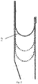
- the rubber bladder of the damping spring 2 rolls on an outer surface of the piston 3, for example, can be moved to positions shown by dotted lines in Fig. 2 .
- the support 4 still firmly abuts against the shock absorber cylinder 1 to reliably support the free end 21 of the damping spring 2 and the free end 31 of the piston 3.
- an outer side of an upper end of the shock absorber cylinder 1 is sleeved with an anti-impact cap 11, and the anti-impact cap 11 plays a role in damping impact.
- the support 4 is arranged between the piston 3 and the anti-impact cap 11.
- the support 4 is disposed between the piston 3 and the shock absorber cylinder 1, and the free end 31 of the piston 3 can be supported on the shock absorber cylinder 1 by the support 4, so that the piston 3 and the shock absorber cylinder 1 are connected in a simple way.
- a fixed connection mode of the piston and the shock absorber cylinder in the prior art over positioning of the piston 3 along an extension direction (i.e., a vertical direction in the figure) of the shock absorber cylinder 1 is avoided.
- the support 4 is provided with an opening 41.
- the opening 41 is arranged on the periphery of the support 4.
- the damping spring 2, the piston 3, and the shock absorber cylinder 1 form a closed air chamber. Due to the support 4, the air chamber is divided into an upper chamber C1 above the base 4 and a lower chamber C2 below the support 4. Through the opening 41 arranged on the support 4, the upper chamber and the lower chamber can communicate with each other, without affecting work of the air spring.
- the figure illustrates a sectional view of the opening 41 of the support 4, and accordingly the opening 41 of the support 4 is shown but a part of the support 4 that is in contact with the anti-impact cap 11 of the shock absorber cylinder 1 is not shown, while this part does exist.
- the support 4 may be fixedly connected to the free end 31 of the piston 3.
- the support 4 and the free end 31 of the piston 3 are integrally constructed, thereby avoiding excessive connection relationships, and reducing the number of parts and assembly steps.
- the shock absorber includes a base 5, and the base 5 is connected to a chassis.
- a fixed end 32 (a lower end in the figure), opposite the free end 31, of the piston 3 abuts against the base 5, thereby supporting the piston 3 and restricting the piston 3 from moving downwards.
- a seal ring 6 is disposed between the fixed end 32 of the piston 3 and the shock absorber cylinder 1.
- the seal ring 6 is embedded in a groove in the base 5, the fixed end 32 of the piston 3 and the base 5 are connected in an interference fit manner at a position near the seal ring 6, so that the air chamber is kept sealed.
- the base 5 and the piston 3 are made of metal, for example.
- the seal ring 6 is made of rubber, for example.
- the shock absorber includes a piston rod 12, the piston rod 12 is inserted in the shock absorber cylinder 1, and the piston rod 12 can move relative to the shock absorber cylinder 1.
- a buffer block 13 is disposed at an upper end of the piston rod 12. The buffer block 13 interacts with the anti-impact cap 11 that sleeves the shock absorber cylinder 1, so as to relieve an impact generated between them.
- the shock absorber further includes a protective cylinder 7 arranged peripherally.
- a fixed end 22, opposite the free end 21, of the damping spring 2 is fixedly connected to the protective cylinder 7.
- a dust cover 8 is disposed beneath the protective cylinder 7 to play a role in protecting components such as the damping spring 2 and the piston 3 inside the dust cover 8.
- the dust cover 8 is a rubber member, for example.
- the shock absorber 100 is substantially arranged between a vehicle body 200 and a chassis 300.
- the shock absorber under a damped motion between the piston rod 12 and the shock absorber cylinder 1, and the cooperation between the air chamber composed of the damping spring 2, the piston 3, and the shock absorber cylinder 1 and elasticity of the damping spring, effects of buffering, damping, and keeping vehicle attitude stable are achieved finally.
- the invention further includes an automobile with the shock absorber according to any one or more of the implementations described above, which therefore has the technical features and the technical effects corresponding to those described above, and no more detailed description is provided herein.
Landscapes
- Engineering & Computer Science (AREA)
- Mechanical Engineering (AREA)
- General Engineering & Computer Science (AREA)
- Fluid-Damping Devices (AREA)
Abstract
Disclosed are a shock absorber and an automobile. The shock absorber includes a shock absorber cylinder and an air spring arranged around the shock absorber cylinder. The air spring includes a damping spring and a piston. A free end of the damping spring is supported at a free end of the piston. A support is disposed between the piston and the shock absorber cylinder. The free end of the piston is supported on the shock absorber cylinder by the support. In the shock absorber according to the invention, the piston and the shock absorber cylinder can be connected in a simple way.
Description
- The invention relates to the field of automobiles, and in particular to a shock absorber and an automobile with such a shock absorber.
- Automobiles have gradually become part of people's lives. As a means of transportation, automobiles are expected to have good riding comfort to relieve bumping of the automobiles driving on uneven roads, and are also expected to have good handling stability to prevent tilting or shaking of vehicle bodies when the automobiles accelerate at the starting or decelerate to brake and turn at a high speed. The quality of an automobile suspension system plays an important role in ensuring the riding comfort and the handling stability. The automobile suspension system is an elastic structure that connects wheels and a vehicle body. A shock absorber is one of major components of the automobile suspension system.
- The stiffness and strength of the shock absorber play an important role in ensuring the riding comfort and the handling stability by means of the automobile suspension system. There is an automobile suspension system in which a piston of an air spring is attached to a shock absorber cylinder or a piston of an air spring is connected to a shock absorber cylinder through a complicated structure. The complicated structure has an unreliable connection relationship, which may result in over positioning.
- Therefore, it is quite necessary to carry out adequate studies on the existing problems or defects including those mentioned above, so as to make improvements.
- The invention provides a shock absorber, which is simple in structure and reliable in connection.
- The shock absorber provided according to an aspect of the invention includes a shock absorber cylinder and an air spring arranged around the shock absorber cylinder. The air spring includes a damping spring and a piston. A free end of the damping spring is supported at a free end of the piston. A support is disposed between the piston and the shock absorber cylinder. The free end of the piston is supported on the shock absorber cylinder by the support.
- In the shock absorber provided according to an aspect of the invention, the support and the free end of the piston are integrally constructed.
- In the shock absorber provided according to an aspect of the invention, the periphery of the support abuts against the shock absorber cylinder.
- In the shock absorber provided according to an aspect of the invention, the support is provided with an opening.
- In the shock absorber provided according to an aspect of the invention, the opening is arranged on the periphery of the support.
- In the shock absorber provided according to an aspect of the invention, the shock absorber cylinder is sleeved with an anti-impact cap, and the support is arranged between the piston and the anti-impact cap.
- The shock absorber provided according to an aspect of the invention includes a base, and a fixed end, opposite the free end, of the piston abuts against the base.
- In the shock absorber provided according to an aspect of the invention, a seal ring is disposed between the fixed end of the piston and the shock absorber cylinder.
- The shock absorber provided according to an aspect of the invention includes a piston rod, the piston rod is inserted into the shock absorber cylinder, and the piston rod can move relative to the shock absorber cylinder.
- The shock absorber provided according to an aspect of the invention includes a protective cylinder disposed peripherally, and a fixed end, opposite the free end, of the damping spring is fixedly connected to the protective cylinder.
- The shock absorber provided according to an aspect of the invention is arranged between a vehicle body and a chassis.
- In addition, the invention provides an automobile with such a shock absorber. Since the automobile has the shock absorber according to the invention, it is possible for the automobile to have the advantages as described above.
- The beneficial effects of the invention include: the support is disposed between the piston and the shock absorber cylinder, and the free end of the piston can be supported on the shock absorber cylinder by the support, so that the piston and the shock absorber cylinder are connected in a simple way, and over positioning of the piston along an extension direction of the shock absorber cylinder is avoided.
- The disclosure of the invention is now described with reference to accompanying drawings. It should be appreciated that the accompanying drawings are merely used for the purpose of illustration, and are not intended to limit the scope of protection of the invention. In the accompanying drawings, unless otherwise specified, the same reference numerals are used to refer to the same components. In the figures:
-
Fig. 1 illustrates a shock absorber according to an implementation of the invention; -
Fig. 2 illustrates a movement mode of a damping spring in the shock absorber inFig. 1 , where dotted lines show different movement positions of the damping spring; and -
Fig. 3 illustrates a positional relationship between the shock absorber inFig. 1 and a vehicle body and a chassis. - It can be readily understood that according to the technical solutions of the invention, a person of ordinary skill in the art may propose multiple interchangeable structures and implementations without changing the essential spirit of the invention. Therefore, the following specific implementations and the accompanying drawings are merely exemplary descriptions of the technical solutions of the invention, and should not be construed as the entirety of the invention or construed as limiting the technical solutions of the invention.
- Directional terms, such as up, down, left, right, front, rear, front side, back side, top, and bottom, which are or may be mentioned in this description, are defined with respect to the structures shown in the accompanying drawings, and are relative concepts, and therefore may correspondingly vary depending on different positions and different conditions in use. Therefore, these or other directional terms should not be construed as restrictive terms as well.
- In the description below, various parameters and components are described for embodiments of different structures, and these specific parameters and components are merely examples and not intended to limit the embodiments of this application.
- An implementation according to the invention is shown with reference to
Fig. 1 . It can be seen therefrom: ashock absorber 100 includes ashock absorber cylinder 1 and an air spring arranged around theshock absorber cylinder 1. The air spring includes adamping spring 2 and apiston 3. The damping spring is constructed as a rubber bladder, for example. Afree end 21 of the dampingspring 2 is supported at a free end 31 (an upper end in the figure) of thepiston 3. Exemplarily, thefree end 21 of the dampingspring 2 is provided with a clamp 9. The clamp 9 can be clamped to a protrusion arranged on thepiston 3. The clamp 9 clamps thefree end 31 of thepiston 3 inwards on an outer surface of the protrusion of thepiston 3 such that thefree end 21 of thedamping spring 2 is supported at thefree end 31 of thepiston 3. Asupport 4 is disposed between thepiston 3 and theshock absorber cylinder 1, and thefree end 31 of thepiston 3 is supported on theshock absorber cylinder 1 by thesupport 4. In an installed state, the periphery of thesupport 4 abuts against theshock absorber cylinder 1. - Referring to
Fig. 2 , in a working process of the shock absorber, a relative position of the air spring changes. Thefree end 21 of the dampingspring 2 drives thefree end 31 of thepiston 3 to move vertically along theshock absorber cylinder 1. The rubber bladder of thedamping spring 2 rolls on an outer surface of thepiston 3, for example, can be moved to positions shown by dotted lines inFig. 2 . In this process, thesupport 4 still firmly abuts against theshock absorber cylinder 1 to reliably support thefree end 21 of the dampingspring 2 and thefree end 31 of thepiston 3. - In the figure, exemplarily, an outer side of an upper end of the
shock absorber cylinder 1 is sleeved with ananti-impact cap 11, and theanti-impact cap 11 plays a role in damping impact. Thesupport 4 is arranged between thepiston 3 and theanti-impact cap 11. - In the shock absorber according to the invention, the
support 4 is disposed between thepiston 3 and theshock absorber cylinder 1, and thefree end 31 of thepiston 3 can be supported on theshock absorber cylinder 1 by thesupport 4, so that thepiston 3 and theshock absorber cylinder 1 are connected in a simple way. Compared with a fixed connection mode of the piston and the shock absorber cylinder in the prior art, over positioning of thepiston 3 along an extension direction (i.e., a vertical direction in the figure) of theshock absorber cylinder 1 is avoided. - In the implementation shown in
Fig. 1 , thesupport 4 is provided with anopening 41. Exemplarily, theopening 41 is arranged on the periphery of thesupport 4. In the working process of the shock absorber, the dampingspring 2, thepiston 3, and theshock absorber cylinder 1 form a closed air chamber. Due to thesupport 4, the air chamber is divided into an upper chamber C1 above thebase 4 and a lower chamber C2 below thesupport 4. Through theopening 41 arranged on thesupport 4, the upper chamber and the lower chamber can communicate with each other, without affecting work of the air spring. - It is to be noted that the figure illustrates a sectional view of the
opening 41 of thesupport 4, and accordingly theopening 41 of thesupport 4 is shown but a part of thesupport 4 that is in contact with theanti-impact cap 11 of theshock absorber cylinder 1 is not shown, while this part does exist. - The
support 4 may be fixedly connected to thefree end 31 of thepiston 3. In a preferred implementation according to the invention, thesupport 4 and thefree end 31 of thepiston 3 are integrally constructed, thereby avoiding excessive connection relationships, and reducing the number of parts and assembly steps. - Still further, the shock absorber includes a
base 5, and thebase 5 is connected to a chassis. A fixed end 32 (a lower end in the figure), opposite thefree end 31, of thepiston 3 abuts against thebase 5, thereby supporting thepiston 3 and restricting thepiston 3 from moving downwards. Aseal ring 6 is disposed between thefixed end 32 of thepiston 3 and theshock absorber cylinder 1. For example, theseal ring 6 is embedded in a groove in thebase 5, thefixed end 32 of thepiston 3 and thebase 5 are connected in an interference fit manner at a position near theseal ring 6, so that the air chamber is kept sealed. Thebase 5 and thepiston 3 are made of metal, for example. Theseal ring 6 is made of rubber, for example. - In the implementation shown in
Fig. 1 , the shock absorber includes apiston rod 12, thepiston rod 12 is inserted in theshock absorber cylinder 1, and thepiston rod 12 can move relative to theshock absorber cylinder 1. Abuffer block 13 is disposed at an upper end of thepiston rod 12. Thebuffer block 13 interacts with theanti-impact cap 11 that sleeves theshock absorber cylinder 1, so as to relieve an impact generated between them. - The shock absorber further includes a
protective cylinder 7 arranged peripherally. Afixed end 22, opposite thefree end 21, of the dampingspring 2 is fixedly connected to theprotective cylinder 7. In the implementation shown inFig. 1 , adust cover 8 is disposed beneath theprotective cylinder 7 to play a role in protecting components such as the dampingspring 2 and thepiston 3 inside thedust cover 8. Thedust cover 8 is a rubber member, for example. - Referring to
Fig. 3 , theshock absorber 100 is substantially arranged between avehicle body 200 and achassis 300. In the working process of the shock absorber, under a damped motion between thepiston rod 12 and theshock absorber cylinder 1, and the cooperation between the air chamber composed of the dampingspring 2, thepiston 3, and theshock absorber cylinder 1 and elasticity of the damping spring, effects of buffering, damping, and keeping vehicle attitude stable are achieved finally. - The invention further includes an automobile with the shock absorber according to any one or more of the implementations described above, which therefore has the technical features and the technical effects corresponding to those described above, and no more detailed description is provided herein.
- The technical scope of this application is not merely limited to the above description. A person skilled in the art can make various variations and modifications to the above embodiments without departing from the technical concept of this application, and these variations and modifications shall fall within the scope of protection of this application.
Claims (12)
- A shock absorber, comprising a shock absorber cylinder (1) and an air spring arranged around the shock absorber cylinder (1), wherein the air spring comprises a damping spring (2) and a piston (3), a free end (21) of the damping spring (2) is supported at a free end (31) of the piston (3), a support (4) is disposed between the piston (3) and the shock absorber cylinder (1), and the free end (31) of the piston (3) is supported on the shock absorber cylinder (1) by the support (4).
- The shock absorber according to claim 1, wherein the support (4) and the free end (31) of the piston (3) are integrally constructed.
- The shock absorber according to claim 1 or 2, wherein the periphery of the support (4) abuts against the shock absorber cylinder (1).
- The shock absorber according to claim 3, wherein the support (4) is provided with an opening (41).
- The shock absorber according to claim 4, wherein the opening (41) is arranged on the periphery of the support (4).
- The shock absorber according to any one of claims 1 to 5, wherein the shock absorber cylinder (1) is sleeved with an anti-impact cap (11), and the support (4) is arranged between the piston (3) and the anti-impact cap (11).
- The shock absorber according to any one of claims 1 to 6, wherein the shock absorber comprises a base (5), and a fixed end (32), opposite the free end (31), of the piston (3) abuts against the base (5).
- The shock absorber according to claim 7, wherein a seal ring (6) is disposed between the fixed end (32) of the piston (3) and the shock absorber cylinder (1).
- The shock absorber according to any one of claims 1 to 8, wherein the shock absorber comprises a piston rod (12), the piston rod (12) is inserted into the shock absorber cylinder (1), and the piston rod (12) is able to move relative to the shock absorber cylinder (1).
- The shock absorber according to any one of claims 1 to 9, wherein the shock absorber comprises a protective cylinder (7) arranged peripherally, and a fixed end (22), opposite the free end (21), of the damping spring (2) is fixedly connected to the protective cylinder (7).
- The shock absorber according to any one of claims 1 to 10, wherein the shock absorber is arranged between a vehicle body and a chassis.
- An automobile, comprising the shock absorber according to any one of claims 1 to 11.
Applications Claiming Priority (1)
| Application Number | Priority Date | Filing Date | Title |
|---|---|---|---|
| CN202110094479.XA CN112682458A (en) | 2021-01-25 | 2021-01-25 | Shock absorber and car |
Publications (1)
| Publication Number | Publication Date |
|---|---|
| EP4027034A1 true EP4027034A1 (en) | 2022-07-13 |
Family
ID=75459094
Family Applications (1)
| Application Number | Title | Priority Date | Filing Date |
|---|---|---|---|
| EP22150542.3A Pending EP4027034A1 (en) | 2021-01-25 | 2022-01-07 | Shock absorber and automobile |
Country Status (3)
| Country | Link |
|---|---|
| US (1) | US11623491B2 (en) |
| EP (1) | EP4027034A1 (en) |
| CN (1) | CN112682458A (en) |
Cited By (1)
| Publication number | Priority date | Publication date | Assignee | Title |
|---|---|---|---|---|
| DE102024201405A1 (en) * | 2024-02-15 | 2025-08-21 | Continental Automotive Technologies GmbH | Method for expanding a protective bellows of a motor vehicle air spring and air spring with a protective bellows |
Citations (5)
| Publication number | Priority date | Publication date | Assignee | Title |
|---|---|---|---|---|
| US20030127781A1 (en) * | 2002-01-10 | 2003-07-10 | Michael Fritz | Pneumatic-spring wheel-suspension leg |
| DE102005052801B4 (en) * | 2005-11-05 | 2011-03-17 | Man Nutzfahrzeuge Ag | Air spring for a motor vehicle |
| US20170219041A1 (en) * | 2014-08-04 | 2017-08-03 | Firestone Industrial Products Company, Llc | Support and carrier assemblies as well as end member assemblies and gas spring and damper assemblies including same |
| US20180298974A1 (en) * | 2015-09-11 | 2018-10-18 | Vibracoustic Cv Air Springs Gmbh | Air spring with several damping devices |
| US10618366B2 (en) * | 2016-07-08 | 2020-04-14 | Continental Automotive Systems, Inc. | Vehicle air strut with twist lock closure cover |
Family Cites Families (9)
| Publication number | Priority date | Publication date | Assignee | Title |
|---|---|---|---|---|
| DE10009912C1 (en) * | 2000-03-01 | 2001-09-06 | Continental Ag | Pneumatic spring with two-part casing has elastic bearing in form of annular section of hollow ball |
| DE102004012881A1 (en) * | 2004-03-16 | 2005-10-06 | Daimlerchrysler Ag | Gas spring system with centrally guided hose bellows |
| KR101094215B1 (en) * | 2009-09-07 | 2011-12-14 | 주식회사 만도 | Air suspension |
| US9296272B2 (en) * | 2010-10-18 | 2016-03-29 | Firestone Industrial Products Company, Llc | Gas spring and gas damper assembly and method |
| JP6006109B2 (en) * | 2012-12-25 | 2016-10-12 | 株式会社ショーワ | Damper with air spring |
| US10125840B2 (en) * | 2014-10-17 | 2018-11-13 | Continental Automotive Systems, Inc. | Air spring hybrid piston assembly |
| DE102015115400B4 (en) * | 2015-09-11 | 2021-09-30 | Vibracoustic Cv Air Springs Gmbh | Air spring |
| US10173488B2 (en) * | 2016-12-05 | 2019-01-08 | Continental Automotive Systems, Inc. | Air spring hanging piston bearing |
| DE102018204485A1 (en) * | 2017-07-07 | 2019-01-10 | Continental Teves Ag & Co. Ohg | Air strut with sealed cap |
-
2021
- 2021-01-25 CN CN202110094479.XA patent/CN112682458A/en active Pending
-
2022
- 2022-01-07 EP EP22150542.3A patent/EP4027034A1/en active Pending
- 2022-01-24 US US17/582,146 patent/US11623491B2/en active Active
Patent Citations (5)
| Publication number | Priority date | Publication date | Assignee | Title |
|---|---|---|---|---|
| US20030127781A1 (en) * | 2002-01-10 | 2003-07-10 | Michael Fritz | Pneumatic-spring wheel-suspension leg |
| DE102005052801B4 (en) * | 2005-11-05 | 2011-03-17 | Man Nutzfahrzeuge Ag | Air spring for a motor vehicle |
| US20170219041A1 (en) * | 2014-08-04 | 2017-08-03 | Firestone Industrial Products Company, Llc | Support and carrier assemblies as well as end member assemblies and gas spring and damper assemblies including same |
| US20180298974A1 (en) * | 2015-09-11 | 2018-10-18 | Vibracoustic Cv Air Springs Gmbh | Air spring with several damping devices |
| US10618366B2 (en) * | 2016-07-08 | 2020-04-14 | Continental Automotive Systems, Inc. | Vehicle air strut with twist lock closure cover |
Cited By (2)
| Publication number | Priority date | Publication date | Assignee | Title |
|---|---|---|---|---|
| DE102024201405A1 (en) * | 2024-02-15 | 2025-08-21 | Continental Automotive Technologies GmbH | Method for expanding a protective bellows of a motor vehicle air spring and air spring with a protective bellows |
| DE102024201405B4 (en) | 2024-02-15 | 2026-03-26 | Aumovio Germany Gmbh | Method for widening a protective bellows of a motor vehicle air spring |
Also Published As
| Publication number | Publication date |
|---|---|
| CN112682458A (en) | 2021-04-20 |
| US20220234407A1 (en) | 2022-07-28 |
| US11623491B2 (en) | 2023-04-11 |
Similar Documents
| Publication | Publication Date | Title |
|---|---|---|
| US4828232A (en) | Vehicle air suspension strut with compliant cover plate assembly | |
| JP2002531784A (en) | Air spring device | |
| FI100391B (en) | Cab, especially for off-road vehicles | |
| US7337864B2 (en) | Industrial truck with a damped driver's position | |
| US11623491B2 (en) | Shock absorber and automobile | |
| JP2018016306A (en) | Axle suspension | |
| CN210440503U (en) | Shock absorber structure and vehicle | |
| CN110758009B (en) | Adjustable balancing wheel for industrial vehicles | |
| KR100264649B1 (en) | McPherson Independent Suspension System for Automobile | |
| US9254726B2 (en) | Transverse leaf spring bearing unit and transverse leaf spring arrangement for a motor vehicle | |
| CN218287357U (en) | Automobile chassis damping support | |
| CN114738421B (en) | Air spring and damper | |
| US20230191865A1 (en) | Airspring gaiter with sliding joint | |
| CN222522809U (en) | Motorcycle shock absorbing device | |
| JP2003072338A (en) | Suspension for automobile | |
| CN211231381U (en) | Shock absorber upper bracket and automobile shock absorber | |
| CN216768184U (en) | Air spring shock absorber | |
| JPH0231907A (en) | air suspension | |
| CN211423255U (en) | Shock absorber support assembly structure with fixed pin | |
| US11548336B1 (en) | Suspension system having rebound control for a vehicle | |
| CN212579550U (en) | Stable comfortable suspension assembly | |
| KR100911546B1 (en) | Suspension structure of vehicle | |
| CN210526682U (en) | A front suspension upper bracket | |
| JPH0744498Y2 (en) | Cargo handling vehicle | |
| KR20100007181A (en) | Spring upper seat for strut assembly |
Legal Events
| Date | Code | Title | Description |
|---|---|---|---|
| PUAI | Public reference made under article 153(3) epc to a published international application that has entered the european phase |
Free format text: ORIGINAL CODE: 0009012 |
|
| STAA | Information on the status of an ep patent application or granted ep patent |
Free format text: STATUS: REQUEST FOR EXAMINATION WAS MADE |
|
| 17P | Request for examination filed |
Effective date: 20220128 |
|
| AK | Designated contracting states |
Kind code of ref document: A1 Designated state(s): AL AT BE BG CH CY CZ DE DK EE ES FI FR GB GR HR HU IE IS IT LI LT LU LV MC MK MT NL NO PL PT RO RS SE SI SK SM TR |
|
| STAA | Information on the status of an ep patent application or granted ep patent |
Free format text: STATUS: EXAMINATION IS IN PROGRESS |