EP4027008A1 - Wind turbine blades with deflector and method - Google Patents
Wind turbine blades with deflector and method Download PDFInfo
- Publication number
- EP4027008A1 EP4027008A1 EP21382002.0A EP21382002A EP4027008A1 EP 4027008 A1 EP4027008 A1 EP 4027008A1 EP 21382002 A EP21382002 A EP 21382002A EP 4027008 A1 EP4027008 A1 EP 4027008A1
- Authority
- EP
- European Patent Office
- Prior art keywords
- wind turbine
- turbine blade
- blade
- deflector
- deflectors
- Prior art date
- Legal status (The legal status is an assumption and is not a legal conclusion. Google has not performed a legal analysis and makes no representation as to the accuracy of the status listed.)
- Pending
Links
- 238000000034 method Methods 0.000 title claims abstract description 21
- 230000010355 oscillation Effects 0.000 description 6
- 230000000694 effects Effects 0.000 description 3
- 230000009467 reduction Effects 0.000 description 3
- 230000015572 biosynthetic process Effects 0.000 description 2
- 230000001427 coherent effect Effects 0.000 description 2
- 238000005094 computer simulation Methods 0.000 description 2
- 230000005611 electricity Effects 0.000 description 2
- 230000003993 interaction Effects 0.000 description 2
- 238000004519 manufacturing process Methods 0.000 description 2
- 230000000116 mitigating effect Effects 0.000 description 2
- 238000012986 modification Methods 0.000 description 2
- 230000004048 modification Effects 0.000 description 2
- 230000001737 promoting effect Effects 0.000 description 2
- 229920000049 Carbon (fiber) Polymers 0.000 description 1
- 229920002430 Fibre-reinforced plastic Polymers 0.000 description 1
- 230000009471 action Effects 0.000 description 1
- 238000004026 adhesive bonding Methods 0.000 description 1
- 230000004075 alteration Effects 0.000 description 1
- 230000002238 attenuated effect Effects 0.000 description 1
- 239000004917 carbon fiber Substances 0.000 description 1
- 239000002131 composite material Substances 0.000 description 1
- 230000003247 decreasing effect Effects 0.000 description 1
- 239000011151 fibre-reinforced plastic Substances 0.000 description 1
- 230000006870 function Effects 0.000 description 1
- 239000003365 glass fiber Substances 0.000 description 1
- 238000005304 joining Methods 0.000 description 1
- 238000012423 maintenance Methods 0.000 description 1
- 239000002184 metal Substances 0.000 description 1
- 229910052751 metal Inorganic materials 0.000 description 1
- 150000002739 metals Chemical class 0.000 description 1
- VNWKTOKETHGBQD-UHFFFAOYSA-N methane Chemical compound C VNWKTOKETHGBQD-UHFFFAOYSA-N 0.000 description 1
- 230000003094 perturbing effect Effects 0.000 description 1
- 230000008569 process Effects 0.000 description 1
- 238000004088 simulation Methods 0.000 description 1
Images


Classifications
-
- F—MECHANICAL ENGINEERING; LIGHTING; HEATING; WEAPONS; BLASTING
- F03—MACHINES OR ENGINES FOR LIQUIDS; WIND, SPRING, OR WEIGHT MOTORS; PRODUCING MECHANICAL POWER OR A REACTIVE PROPULSIVE THRUST, NOT OTHERWISE PROVIDED FOR
- F03D—WIND MOTORS
- F03D13/00—Assembly, mounting or commissioning of wind motors; Arrangements specially adapted for transporting wind motor components
- F03D13/10—Assembly of wind motors; Arrangements for erecting wind motors
-
- F—MECHANICAL ENGINEERING; LIGHTING; HEATING; WEAPONS; BLASTING
- F03—MACHINES OR ENGINES FOR LIQUIDS; WIND, SPRING, OR WEIGHT MOTORS; PRODUCING MECHANICAL POWER OR A REACTIVE PROPULSIVE THRUST, NOT OTHERWISE PROVIDED FOR
- F03D—WIND MOTORS
- F03D1/00—Wind motors with rotation axis substantially parallel to the air flow entering the rotor
- F03D1/04—Wind motors with rotation axis substantially parallel to the air flow entering the rotor having stationary wind-guiding means, e.g. with shrouds or channels
-
- F—MECHANICAL ENGINEERING; LIGHTING; HEATING; WEAPONS; BLASTING
- F03—MACHINES OR ENGINES FOR LIQUIDS; WIND, SPRING, OR WEIGHT MOTORS; PRODUCING MECHANICAL POWER OR A REACTIVE PROPULSIVE THRUST, NOT OTHERWISE PROVIDED FOR
- F03D—WIND MOTORS
- F03D1/00—Wind motors with rotation axis substantially parallel to the air flow entering the rotor
- F03D1/06—Rotors
- F03D1/065—Rotors characterised by their construction elements
- F03D1/0675—Rotors characterised by their construction elements of the blades
-
- F—MECHANICAL ENGINEERING; LIGHTING; HEATING; WEAPONS; BLASTING
- F03—MACHINES OR ENGINES FOR LIQUIDS; WIND, SPRING, OR WEIGHT MOTORS; PRODUCING MECHANICAL POWER OR A REACTIVE PROPULSIVE THRUST, NOT OTHERWISE PROVIDED FOR
- F03D—WIND MOTORS
- F03D1/00—Wind motors with rotation axis substantially parallel to the air flow entering the rotor
- F03D1/06—Rotors
- F03D1/0608—Rotors characterised by their aerodynamic shape
- F03D1/0633—Rotors characterised by their aerodynamic shape of the blades
-
- F—MECHANICAL ENGINEERING; LIGHTING; HEATING; WEAPONS; BLASTING
- F05—INDEXING SCHEMES RELATING TO ENGINES OR PUMPS IN VARIOUS SUBCLASSES OF CLASSES F01-F04
- F05B—INDEXING SCHEME RELATING TO WIND, SPRING, WEIGHT, INERTIA OR LIKE MOTORS, TO MACHINES OR ENGINES FOR LIQUIDS COVERED BY SUBCLASSES F03B, F03D AND F03G
- F05B2240/00—Components
- F05B2240/20—Rotors
- F05B2240/30—Characteristics of rotor blades, i.e. of any element transforming dynamic fluid energy to or from rotational energy and being attached to a rotor
- F05B2240/305—Flaps, slats or spoilers
-
- F—MECHANICAL ENGINEERING; LIGHTING; HEATING; WEAPONS; BLASTING
- F05—INDEXING SCHEMES RELATING TO ENGINES OR PUMPS IN VARIOUS SUBCLASSES OF CLASSES F01-F04
- F05B—INDEXING SCHEME RELATING TO WIND, SPRING, WEIGHT, INERTIA OR LIKE MOTORS, TO MACHINES OR ENGINES FOR LIQUIDS COVERED BY SUBCLASSES F03B, F03D AND F03G
- F05B2260/00—Function
- F05B2260/96—Preventing, counteracting or reducing vibration or noise
-
- F—MECHANICAL ENGINEERING; LIGHTING; HEATING; WEAPONS; BLASTING
- F05—INDEXING SCHEMES RELATING TO ENGINES OR PUMPS IN VARIOUS SUBCLASSES OF CLASSES F01-F04
- F05D—INDEXING SCHEME FOR ASPECTS RELATING TO NON-POSITIVE-DISPLACEMENT MACHINES OR ENGINES, GAS-TURBINES OR JET-PROPULSION PLANTS
- F05D2240/00—Components
- F05D2240/20—Rotors
- F05D2240/30—Characteristics of rotor blades, i.e. of any element transforming dynamic fluid energy to or from rotational energy and being attached to a rotor
-
- Y—GENERAL TAGGING OF NEW TECHNOLOGICAL DEVELOPMENTS; GENERAL TAGGING OF CROSS-SECTIONAL TECHNOLOGIES SPANNING OVER SEVERAL SECTIONS OF THE IPC; TECHNICAL SUBJECTS COVERED BY FORMER USPC CROSS-REFERENCE ART COLLECTIONS [XRACs] AND DIGESTS
- Y02—TECHNOLOGIES OR APPLICATIONS FOR MITIGATION OR ADAPTATION AGAINST CLIMATE CHANGE
- Y02E—REDUCTION OF GREENHOUSE GAS [GHG] EMISSIONS, RELATED TO ENERGY GENERATION, TRANSMISSION OR DISTRIBUTION
- Y02E10/00—Energy generation through renewable energy sources
- Y02E10/70—Wind energy
- Y02E10/72—Wind turbines with rotation axis in wind direction
Definitions
- the present disclosure relates to wind turbine blades and methods for reducing wind turbine vibrations. More particularly, the present disclosure relates to wind turbine blades and methods for reducing wind turbine vibrations of one or more components of a wind turbine when the wind turbine is parked or idling.
- Wind turbines are commonly used to supply electricity into the electrical grid.
- Wind turbines of this kind generally comprise a tower and a rotor arranged on the tower.
- the rotor which typically comprises a hub and a plurality of blades, is set into rotation under the influence of the wind on the blades. Said rotation generates a torque that is normally transmitted through a rotor shaft to a generator, either directly or through the use of a gearbox. This way, the generator produces electricity which can be supplied to the electrical grid.
- the wind turbine hub may be rotatably coupled to a front of the nacelle.
- the wind turbine hub may be connected to a rotor shaft, and the rotor shaft may then be rotatably mounted in the nacelle using one or more rotor shaft bearings arranged in a frame inside the nacelle.
- the nacelle is a housing arranged on top of a wind turbine tower that contains and protects e.g. the gearbox (if present) and the generator and, depending on the wind turbine, further components such as a power converter, and auxiliary systems.
- a wind turbine may be stopped or may enter in an idle mode of operation for several reasons. For instance, if the electrical grid is receiving too much energy from a wind farm, a setpoint reduction for the wind farm may be received and some of them may start idling until more energy production is required. Also, a wind turbine may be parked, for example, for performing maintenance on it. In addition, a wind turbine may start idling or may be stopped for security reasons, e.g. if wind gusts may damage the wind turbine.
- the terms idle or idling refer to the fact that the wind turbine blades are (slowly) rotating but no energy is produced, namely because the generator is not connected to the grid.
- a stopped or parked wind turbine may be understood as a wind turbine whose rotor has been locked and is therefore not moving.
- a wind turbine is in operation when its rotor is rotating at a speed high enough to produce energy and the generator of the wind turbine is producing electrical power.
- a wind turbine blade In a first aspect of the present disclosure, a wind turbine blade is provided.
- the wind turbine blade comprises a blade surface, and one or more deflectors attached to the wind turbine blade surface configured to disturb a spanwise component of air flowing around the wind turbine blade.
- the deflector attached to the wind turbine may disturb a spanwise component of air flowing which may occur specifically around an idling or stopped wind turbine blade. Such disturbance may mitigate or even stop vibration of one or more components of a wind turbine, e.g. the wind turbine blade and/or a wind turbine tower.
- a wind turbine e.g. the wind turbine blade and/or a wind turbine tower.
- VIVs vortex-induced vibrations
- SIVs stall-induced vibrations
- distal or “perturbing" a spanwise component of an air flow refers to modify a magnitude, spanwise turbulence coherence, or other characteristics (in particular turbulent vs laminar flow) of the spanwise component without destroying it, i.e. without avoiding the spanwise component.
- a spanwise component keeps existing after an alteration of the airflow. Modifying a magnitude and/or direction of the air flow may perturbate a spanwise component of such air flow.
- the resulting air flow may be more turbulent.
- Figure 1 illustrates a perspective view of one example of a wind turbine 160.
- the wind turbine 160 includes a tower 170 extending from a support surface 150, a nacelle 161 mounted on the tower 170, and a rotor 115 coupled to the nacelle 161.
- the rotor 115 includes a rotatable hub 110 and at least one rotor blade 120 coupled to and extending outwardly from the hub 110.
- the rotor 115 includes three rotor blades 120.
- the rotor 115 may include more or less than three rotor blades 120.
- Each rotor blade 120 may be spaced about the hub 110 to facilitate rotating the rotor 115 to enable kinetic energy to be transferred from the wind into usable mechanical energy, and subsequently, electrical energy.
- the hub 110 may be rotatably coupled to an electric generator 162 ( figure 2 ) positioned within the nacelle 161 to permit electrical energy to be produced.
- FIG 2 illustrates a simplified, internal view of one example of the nacelle 161 of the wind turbine 160 of figure 1 .
- the generator 162 may be disposed within the nacelle 161.
- the generator 162 may be coupled to the rotor 115 of the wind turbine 160 for generating electrical power from the rotational energy generated by the rotor 115.
- the rotor 115 may include a main rotor shaft 163 coupled to the hub 110 for rotation therewith.
- the generator 162 may then be coupled to the rotor shaft 163 such that rotation of the rotor shaft 163 drives the generator 162.
- the generator 162 includes a generator shaft 166 rotatably coupled to the rotor shaft 163 through a gearbox 164.
- rotor shaft 163, gearbox 164, and generator 162 may generally be supported within the nacelle 161 by a support frame or bedplate 165 positioned atop the wind turbine tower 170.
- the nacelle 161 is rotatably coupled to the tower 170 through the yaw system 20 in such a way that the nacelle 161 is able to rotate about a yaw axis YA.
- the yaw system 20 comprises a yaw bearing having two bearing components configured to rotate with respect to the other.
- the tower 170 is coupled to one of the bearing components and the bedplate or support frame 165 of the nacelle 161 is coupled to the other bearing component.
- the yaw system 20 comprises an annular gear 21 and a plurality of yaw drives 22 with a motor 23, a gearbox 24 and a pinion 25 for meshing with the annular gear 21 for rotating one of the bearing components with respect to the other.
- Blades 120 are coupled to the hub 110 with a pitch bearing 100 in between the blade 120 and the hub 110.
- the pitch bearing 100 comprises an inner ring and an outer ring.
- a wind turbine blade may be attached either at the inner bearing ring or at the outer bearing ring, whereas the hub is connected at the other.
- a blade 120 may perform a relative rotational movement with respect to the hub 110 when a pitch system 107 is actuated.
- the inner bearing ring may therefore perform a rotational movement with respect to the outer bearing ring.
- the pitch system 107 of Figure 2 comprises a pinion 108 that meshes with an annular gear 109 provided on the inner bearing ring to set the wind turbine blade into rotation around a pitch axis PA.
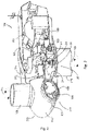
- FIG. 3 A schematic perspective view of a wind turbine blade 120, e.g. one of the rotor blades 120 shown in figure 1 , is illustrated as an example in figure 3 .
- the rotor blade 120 includes a blade root 210, a blade tip 220, a leading edge 260 and a trailing edge 270.
- the blade root 210 is configured for mounting the rotor blade 120 to the hub 110 of a wind turbine 160.
- the wind turbine blade 120 extends lengthwise between the blade root 210 and the blade tip 220.
- a span 230 defines a length of the rotor blade 120 between said blade root 210 and blade tip 220.
- a chord 280 at a given position of the blade is an imaginary straight line joining the leading edge 260 and the trailing edge 270, the cross-section generally having airfoil shaped cross-section.
- a chordwise direction is substantially perpendicular to a spanwise direction.
- the chord 280 may vary in length as the rotor blade 120 extends from the blade root 210 to the blade tip 220.
- the wind turbine blade 120 also includes a pressure side 240 and a suction side 250 extending between the leading edge 260 and the trailing edge 270.
- the rotor blade 120 has an aerodynamic profile and thus an airfoil shaped cross-section 290, such as a symmetrical or cambered airfoil-shaped cross-section.
- Wind turbine blade 120 further includes a deflector 300 attached to a suction side 250 according to the example of figure 3 .
- a deflector 300 may be attached to a pressure side 240.
- a deflector 300 may extend along both suction side 250 and pressure side 240. The function and structure of this deflector 300 will be explained later on.
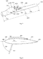
- Figure 4 illustrates a schematic example of a cross-section at a spanwise position of a wind turbine blade 120, e.g. the wind turbine blade 120 of any of figures 1 and 3.
- Figure 4 shows an air flow 320, which may reach a wind turbine blade 120 with an angle of attack 310 that is much higher than usual in operation, e.g around 60-70o.
- Such an angle of attack may occur e.g. when the wind turbine is parked or idling.
- a yaw system of the wind turbine may be inoperative, and the blades may be in a vane position. Because yawing of the rotor does not occur, wind may come from any angle at a wind turbine.
- the angle of attack 310 is measured between the direction of incoming wind and dashed line 305, which indicates a chordwise direction 305. Vibration may happen when a wind turbine 160 is parked or idling and in particular when air flow 320 may reach a wind turbine blade 120 from several directions. Air flow 320 reaching a wind turbine blade 120 from several directions may be referred to as crossflow. Crossflow may enable angles of attack 310 to be high enough to cause one or more wind turbine components to oscillate. The terms vibrating and oscillating may be used interchangeably throughout this disclosure.
- VIV blade vortex induced vibrations
- SIV Stall Induced Vibrations
- the blade may essentially form a bluff body.
- the incoming wind may also have a spanwise component.
- Vibrations in wind turbines may for instance be vortex-induced vibrations (VIVs).
- VIVs vortex-induced vibrations
- wind flowing around a wind turbine blade 120 may cause vortex formation and shedding 510, e.g. in the form of a von Karman vortex street 510 downstream of the wind turbine blade 120.
- the vortex shedding may cause one or more wind turbine blades 120 and/or the wind turbine tower 170 to start oscillating.
- a wind turbine blade 120 may start oscillating in a plane substantially parallel to a chord 280 of the wind turbine blade 120, as schematically illustrated by arrow 520 in figure 5 .
- VIVs may stress structural components of the wind turbine 160.
- angles of attack 310 which may cause VIVs may be angles between 60 and 120o, and specifically between 70o and 110o. In another example, such angles 310 may be between 240 and 300o. Inflow angles (angle between a chord direction and wind direction in a horizontal plane) between 20 and 50o may also favor VIVs and/or SIVs. As such angles of attack 310 may not be encountered when a wind turbine 160 is operating normally, e.g. when the wind turbine blades 120 may be yawed and/or pitched, VIVs may mainly take place and may become particularly problematic when a wind turbine 160 is parked or idling.
- Vibrations may also be stall-induced vibrations (SIVs).
- the angle of attack 310 is such that it causes air flow to separate from a surface of a wind turbine blade 120 and vortex 610 formation and flow downstream the wind turbine blade 120.
- the angle of attack 310 of an airflow may be between 15o and 30o.
- a schematic illustration of this effect is illustrated in figure 6 .
- These vortices 610 may cause the wind turbine blade 120 to oscillate in a plane substantially parallel and/or inclined with respect to a chord 280 of the wind turbine blade 120, as schematically illustrated by arrows 620 in figure 6 . Again, such oscillations may cause stress in structural components of the wind turbine 160 and cause fatigue damage and even potentially cause catastrophic failure of the wind turbine.
- SIVs may affect an idling, and more particularly, a parked wind turbine.
- a wind turbine blade 120 may comprise a deflector 300 attached to the wind turbine blade 120 such that the deflector 300 perturbates or disturbs a spanwise component 410 of air 320 flowing around the wind turbine blade 120 when the wind turbine blade 120 is mounted to a wind turbine 160 and the wind turbine 160 is parked or idling.
- a deflector 300 in cross-section may be seen in figure 4 .
- Disturbing a spanwise component 410 (see figure 3 ) of air 320 flowing around the wind turbine blade 120 may reduce and even stop vibration of one or more components of a wind turbine 160, e.g. the wind turbine blade 120.
- disturbing a spanwise component 410 of air 120 flowing around a wind turbine blade 120 may reduce and even stop vibration of the entire wind turbine 160.
- VIVs and/or SIVs may be mitigated.
- a direction of air 320 flowing around a wind turbine 120 may be decomposed into a spanwise component 410, a chordwise component 405 and a vertical component 415.
- the vertical component is perpendicular to the spanwise component 410 and to the chordwise component 405.
- a deflector 300 may modify a magnitude and/or direction of air flow 320, and in particular may disturb a spanwise component 410 of the air flow 320 without destroying, i.e. making disappear, the spanwise component 410, as schematically shown in figure 3 .
- the chordwise component 405 which mostly dominates in normal turbine operation, may not be destroyed either.
- deflector 300 modifies a direction and/or magnitude of air flow 320, and in particular a magnitude of a spanwise component 410 of said air flow 320. Passing against and over deflector 300, air flow 320 may become more turbulent. A magnitude of a spanwise component 410' of the resulting air flow 325 may be enhanced. I.e., spanwise flow 410' after the interaction of an incoming airflow with a deflector 300 may be promoted.
- an incoming air flow may refer to an air flow approaching and surrounding a wind turbine blade 120 before meeting the deflector 300.
- a resulting air flow 325 may be understood as the air flow 325 remaining after the incoming air flow has met deflector 300.
- the wind turbine blade 120 is configured to make vortex sheddings 510 uncoherent along the span of the blade.
- vortex shedding may occur at several positions along a length or span 230 of a wind turbine blade 120.
- a von Karman street 510 may be imagined downstream of all these positions.
- S1, S2, S3 and S4 may be formed as schematically illustrated in figure 7 .
- S1 to S4 may propagate in a plane xz.
- the z axis is perpendicular to the x and the y axes, wherein the x axis is parallel to a chord 280 of the wind turbine blade 120 and the y axis is parallel to a length 230 of the wind turbine blade 120.
- S1 and S2 may be spanwise coherent because the forces F1 and F2 cause to the wind turbine blade 120 by S1 and S2, respectively, substantially go in the same direction at the same time. In the example of figure 7 , F1 and F2 go in the +x direction. Therefore, these two forces add up and vibration e.g. of the wind turbine blade 120 may be enhanced.
- S3 and S4 may not be spanwise coherent because in this example the forces F3 and F4 caused to the wind turbine blade 120 by S3 and S4, respectively, substantially go in opposite directions at the same time.
- F3 goes in the +x direction and F4 goes in the +x direction.
- an offset 710 between S3 and S4 may exist.
- an offset 710 may be measured in a direction substantially perpendicular to a length 230 and a chord 280 of the wind turbine blade 120, i.e. in a z direction.
- the offset 710 is such that F3 and F4 go in opposite directions with a same magnitude.
- force F3 may be cancelled by force F4, and vibrations, e.g. of the wind turbine blade 120, may be reduced.
- making two or more vortex sheddings 510 to be spanwise uncoherent may be understood as decorrelating the vortex sheddings 510, e.g. by increasing an offset among the vortex sheddings 510.
- a deflector 300 attached to a wind turbine blade 120 may make vortex sheddings 510 spanwise uncoherent by decorrelating them, e.g. by making them less similar in the vicinity of a same point in the y-axis of figure 7 . This may cause an offset 710 between them. Vibrations, e.g. VIVs, may be accordingly reduced.
- decorrelating two or more vortex sheddings 510 may not necessarily cause forces in opposite directions to arise. For instance, forces may still act in a same direction as before decorrelation, but a magnitude and/or a phase matching of one or more of the forces may have decreased. Thus, a force exerted by the plurality of vortex sheddings 510 acting on a wind turbine blade 120 may be lower than before the decorrelation. In such a case, vibrations may also be reduced.
- the deflectors of the wind turbine blade 120 may be configured to promote a turbulent air flow 325, resulting from the crossflow component in idling or parked condition, along a length 230 of the wind turbine blade 120.
- promoting a turbulent air flow 325 along a 230 length of the wind turbine blade 120 may refer to the fact that air flow 325 after passing over deflector 300 is more turbulent than an incoming air flow and/or the air flow without the deflector. If air flow becomes more turbulent after meeting deflector 300, in particular in a spanwise direction, oscillations in a wind turbine (particularly a parked or idling wind turbine) may be reduced.
- the spanwise component 325 is relatively small or negligent, and the deflector 320 does not disturb the normal flow allowing the blade operate as designed at optimal conditions.
- a turbulent air flow 325 occurring over this surface may modify the air flowing over it and vibrations of the blade 120 may be reduced. This may reduce vibrations of the wind turbine 160, in particular VIVs and/or SIVs.
- the deflector 300 may be an elongated deflector 300 attached to the wind turbine blade 120 such that a length of the deflector 300 follows a perimeter of the wind turbine blade 120 in cross-section and the deflector 300 protrudes from a surface of the wind turbine blade 120.
- An example of an elongated deflector 300 may be seen in figure 4 .
- Deflector 300 may be substantially a flat plate extending both along the pressure side and the suction side and from the leading edge to the trailing edge.
- the elongated deflector 300 protrudes substantially perpendicular to a local surface of the wind turbine blade 120.
- a local surface may be understood as a surface to which the elongated deflector is attached to.
- Such perpendicularity or in other words, a plane of symmetry defined by a length 301 and a height 302 of the deflector 300, may enable homogenizing an action by the deflector 300 on an incoming air flow independently of its direction.
- the elongated deflector 300 may not protrude substantially perpendicular to a local surface. For example, it may happen that an angle of inclination between the deflector 300 and a local surface of the wind turbine blade 120 to which deflector 300 is attached to may be selected according to particularities of air flowing in the region where a wind turbine 160 is located.
- the elongated deflector 300 may be attached to a wind turbine blade 120 at any distance from the tip 220 of the wind turbine blade 120.
- the body 300 is attached to the wind turbine blade 120 at 20% to 80% of the span, and specifically between 20 and 60% of the span.
- This range of distances enables achieving a balance between mitigating vibrations and affecting the performance of the wind turbine 160 in normal operation. For instance, if a deflector 300 is placed outside this range, e.g. close to the root 210 or close to the tip 220, the deflector 300 may miss a lot of incoming airflow or may cause excessive noise, respectively. Thus, in this range vibrations may be reduced while the performance of the wind turbine 160 may not, or may barely be, negatively affected.
- a wind turbine blade 120 may have a length 230 or span 230 of 70 m and a deflector 300 may be attached 30 m away from the blade root 210. More than one deflector may be installed in some cases, especially for very long blades.
- One way of determining a suitable location for deflectors according to the present disclosure is to use an aeroelastic analysis of a blade along its length to calculate or estimate which portions of the blade contribute positively to a vibration (i.e. the wind transfers energy to the blade) and which portion of the blade reduce a vibration (i.e. these portions transfer energy from the blade to the wind).
- One measure to determine such a contribution is the aerodynamic work per cycle.
- the deflectors may be placed particularly in areas of the blade where the contribution of the blade to a vibration is positive.
- Such a process may be reiterative, i.e. a simulation or aeroelastic analysis is made on a simulated blade having one or more deflectors.
- a height 302 of the deflector 300 is between 0.1 and 2 times of the local (maximum) thickness of the airfoil of the wind turbine blade 120. In this range, a balance between vibration reduction and affecting the performance of the wind turbine 160 may be achieved. If the height 302 of the deflector 300 is too small, e.g. less than 0.1 times the local thickness of the wind turbine blade 120, vibrations may not be sufficiently attenuated, since the deflector may not sufficiently disturb a spanwise flow. If the height 302 of the deflector 300 is too big, e.g. more than twice the local thickness of the wind turbine blade 120, the performance of the wind turbine 160 may be excessively affected in a negative way. Also, a relatively large deflector might add significant weight to the blade. In an example, a height 302 of deflector 300 may be 40 cm.
- a length 301 of the deflector 300 may extend partially or totally over a local chord of the blade.
- a length 301 of the deflector 300 extends partially along the profile of the local cross-section of the blade, i.e. only a portion of a blade between the leading edge and the trailing edge is covered.
- the deflector 300 covers, at least in part, at least one of: a leading edge 260 and a trailing edge 270 of the wind turbine blade 120.
- a length 301 of the deflector 300 may extend from the local leading edge to the local trailing edge, and follow the entire local profile.
- the dimensions of the deflector 300 and its position on the wind turbine blade 120 may be chosen depending e.g. on shape and dimensions of the wind turbine blade. In this regard, computer simulations may be performed in order to optimize the dimensions and location of the deflector 300 on a wind turbine blade 120.
- a top 303 of the deflector 300 comprises irregularities 304, i.e. along its length, the deflector may have a non-constant height.
- a top 303 may be understood as a side of the deflector 300 opposed to the side of the deflector 300 which is attached to the wind turbine blade 120.
- Figure 8 shows an example of a deflector 300 having a top 303 including irregularities 304.
- Irregularities 304 may include protrusions and/or recesses.
- the irregularities 304 may extend over the entire top 303 of the deflector 300, as shown in figure 8 , or may extend over a portion of it.
- Figure 8 shows an undulated top 303 of the deflector 300, but irregularities 304 having a different shape, e.g. a triangular or rectangular shape, are possible. Irregularities 304 may facilitate disturbing a spanwise component of air flowing around the wind turbine blade as disclosed herein.
- a deflector 300 may be made from (light) metals or composite materials such as fiber-reinforced polymers. In some examples, a deflector 300 may be made of carbon fiber or glass fiber. A deflector 300 may be strong and lightweight accordingly.
- a deflector 300 may in some examples be similar to a flat plate or fence, generally similar to boundary layer fences or vortilons on a wing plane. I.e. they may be relatively thin and extend from both the pressure surface and suction surface of a blade.
- wing fences and vortilons differ from the purpose and functioning of a deflector 300 described herein.
- wing fences on an aircraft wind aim at stopping or destroying an air flow spanwise component
- the objective is not to eliminate a spanwise component (this would in any case hardly be possible depending on the wind direction). Rather, the objective is to disturb an air flow spanwise component, e.g. by making it more turbulent.
- an air flow spanwise component may be enhanced.
- the functioning and objective of the devices on plane wings are distinct, and even rather opposite, than the ones of deflectors 300.
- a wind turbine 160 e.g. the wind turbine 160 of figure 1
- a wind turbine 160 comprises a wind turbine tower 170, a nacelle 161 on top of the tower 170, a rotor 115 mounted to the nacelle 161 and one or more wind turbine blades 120 comprising one or more wind turbine blades 120 including one or more deflectors 300 as described herein.
- a wind turbine blade which comprises a blade surface extending from a blade root to a blade tip, and having a pressure surface and a suction surface, wherein a span of the blade is defined by a distance between the blade root and the blade tip.
- the blade comprising a deflector attached to the blade surface may is configured to promote turbulence of a spanwise flow along the wind turbine blade.
- the deflector may promote turbulence of a spanwise flow along a span of the wind turbine blade in idling or parked conditions in presence of crossflow wind.
- a wind turbine blade 120 comprising one or more of such a deflectors 300 may reduce vibrations of one or more components of a wind turbine 160, e.g. by disturbing a spanwise component 410 of air flowing around the wind turbine blade 120.
- the wind turbine blade 120 may be configured to make two or more vortex sheddings 510 to be spanwise uncoherent.
- the wind turbine blade 120 may be configured to create a spanwise-uncorrelated turbulent air flow along a length 230 of the wind turbine blade 120. Accordingly, VIVs and/or SIVs may be in particular reduced.
- the elongated deflector 300 is attached to the wind turbine blade 120 between 0.2 and 0.8 times of a length 230 of the wind turbine blade 120 from the tip 220 of the wind turbine blade 120. This range of distances may provide for a more effective oscillation mitigation as explained above.
- a height 302 of the elongated deflector 300 is between 0.1 and 2 times of a local wind turbine blade 120 thickness. Also as indicated above, a height 302 in this range may provide for vibration reduction without excessively affecting a wind turbine 160 performance in a negative way.
- the elongated deflector 300 may cover, at least in part, a leading edge 260 and/or a trailing edge 270 of the wind turbine blade 120.
- a top 303 of the deflector 300 comprises irregularities 304.
- a wind turbine 160 comprising a wind turbine tower 170, a nacelle 161 on top of the tower 170, a rotor 115 mounted to the nacelle 160, and one or more wind turbine blades 120 including one or more deflectors 300 according to this aspect mounted to the rotor 115 is provided.
- the present disclosure provides a method 900 for installing a wind turbine blade.
- the method comprises providing a wind turbine blade having one or more deflectors attached to the wind turbine blade, wherein the deflectors are configured to disturb a spanwise component of an air flow along the wind turbine blade, installing the wind turbine blade to a hub of a wind turbine, and removing the deflectors from the wind turbine blade before starting operation of the wind turbine.
- FIG 9 an example of a method 900 for installing a wind turbine blade.
- the method includes, at block 905, providing a wind turbine blade 120, one or more deflectors 300.
- one or more deflectors may be attached to the wind turbine blade.
- a blade may be provided from a manufacturing facility with the deflectors already attached.
- the one or more deflectors 300 may be as any of the deflectors 300 described herein.
- a deflector 300 may be an elongated deflector, and more in particular an elongated flat plate.
- the deflector 300 may be formed by a single piece, but in the example of the deflector 300 completely surrounding a wind turbine blade 120 cross-section, the deflector 300 may be formed by more than one piece and the pieces may be attached to one another to form the deflector 300. The assembly of the plurality of pieces may be done before attaching the deflector 300 to the wind turbine blade 120 or the pieces may be attached to the blade 120 then among them to form deflector 300. Alternatively, the deflector 300 may be a single piece and it may be slid along the wind turbine blade 120 until its final position.
- Method 900 may further comprise, at block 920, mounting the wind turbine blade 120 to the wind turbine 160. This step may be performed before attaching one or more deflectors 300 to the wind turbine blade 120 or after attaching them.
- the wind turbine 160 may further comprise a nacelle 161 on top of the tower 170 and a rotor 115 mounted to the nacelle 161, and the method may further comprise mounting the wind turbine blade 120 to the rotor 115 of the wind turbine 160.
- the attachment between a deflector 300 and a wind turbine blade 120 may or may not be permanent. I.e., in some examples, once one or more deflectors 300 are attached to a wind turbine blade 120, they may be left on the wind turbine blade 120 no matter if the wind turbine 160 is operating or is idling or parked. In some other examples, at block 930, one or more deflectors 300 may be detached from the wind turbine blade 120. In this case, the method further comprises removing one or more deflectors 300 from a wind turbine blade 120 before starting operation of the wind turbine 160. If the deflectors 300 may only be on the wind turbine blade 120 when the wind turbine 160 is not in operation, they may have a bigger height 302, e.g. more than one time of a local wind turbine blade 120 thickness.
- a deflector 300 or a piece of a deflector 300, may be attached to a wind turbine blade 120 by using at least one of gluing, or mechanically fastening.
- the operation of the wind turbine may be (re)started at block 940.
Abstract
Description
- The present disclosure relates to wind turbine blades and methods for reducing wind turbine vibrations. More particularly, the present disclosure relates to wind turbine blades and methods for reducing wind turbine vibrations of one or more components of a wind turbine when the wind turbine is parked or idling.
- Modern wind turbines are commonly used to supply electricity into the electrical grid. Wind turbines of this kind generally comprise a tower and a rotor arranged on the tower. The rotor, which typically comprises a hub and a plurality of blades, is set into rotation under the influence of the wind on the blades. Said rotation generates a torque that is normally transmitted through a rotor shaft to a generator, either directly or through the use of a gearbox. This way, the generator produces electricity which can be supplied to the electrical grid.
- The wind turbine hub may be rotatably coupled to a front of the nacelle. The wind turbine hub may be connected to a rotor shaft, and the rotor shaft may then be rotatably mounted in the nacelle using one or more rotor shaft bearings arranged in a frame inside the nacelle. The nacelle is a housing arranged on top of a wind turbine tower that contains and protects e.g. the gearbox (if present) and the generator and, depending on the wind turbine, further components such as a power converter, and auxiliary systems.
- A wind turbine may be stopped or may enter in an idle mode of operation for several reasons. For instance, if the electrical grid is receiving too much energy from a wind farm, a setpoint reduction for the wind farm may be received and some of them may start idling until more energy production is required. Also, a wind turbine may be parked, for example, for performing maintenance on it. In addition, a wind turbine may start idling or may be stopped for security reasons, e.g. if wind gusts may damage the wind turbine. Throughout this disclosure, the terms idle or idling refer to the fact that the wind turbine blades are (slowly) rotating but no energy is produced, namely because the generator is not connected to the grid. A stopped or parked wind turbine may be understood as a wind turbine whose rotor has been locked and is therefore not moving. Herein it may be understood that a wind turbine is in operation when its rotor is rotating at a speed high enough to produce energy and the generator of the wind turbine is producing electrical power.
- When a wind turbine is parked or idling, the wind may blow against the wind turbine from unusual directions, i.e. different from normal operation. The airflow around the wind turbine may cause the wind turbine to vibrate. Vibrations may stress and even damage one or more wind turbine components, which may compromise the performance of the wind turbine, may increase the need of reparations and may reduce the lifespan of the wind turbine. As an orientation of a wind turbine blade may not be adapted to the direction of the incoming wind, e.g. through yawing as when the wind turbine is operating, the effects of vibrations may be greater or different when the wind turbine is parked or idling than when the wind turbine is operating normally and producing energy.
- In a first aspect of the present disclosure, a wind turbine blade is provided. The wind turbine blade comprises a blade surface, and one or more deflectors attached to the wind turbine blade surface configured to disturb a spanwise component of air flowing around the wind turbine blade.
- In accordance with this aspect, the deflector attached to the wind turbine may disturb a spanwise component of air flowing which may occur specifically around an idling or stopped wind turbine blade. Such disturbance may mitigate or even stop vibration of one or more components of a wind turbine, e.g. the wind turbine blade and/or a wind turbine tower. Without wishing to be bound by theory, in particular vortex-induced vibrations (VIVs) and/or stall-induced vibrations (SIVs) may be reduced.
- Herein, it may be understood that "disturbing" or "perturbing" a spanwise component of an air flow refers to modify a magnitude, spanwise turbulence coherence, or other characteristics (in particular turbulent vs laminar flow) of the spanwise component without destroying it, i.e. without avoiding the spanwise component. Thus, a spanwise component keeps existing after an alteration of the airflow. Modifying a magnitude and/or direction of the air flow may perturbate a spanwise component of such air flow.
- The resulting air flow may be more turbulent.
-
-
Figure 1 illustrates a perspective view of one example of a wind turbine; -
Figure 2 illustrates a simplified, internal view of one example of the nacelle of the wind turbine of thefigure 1 ; -
Figure 3 schematically illustrates a perspective view of an example of a wind turbine blade; -
Figure 4 schematically illustrates an example of a cross-section of the wind turbine blade offigure 3 ; -
Figure 5 schematically illustrates an example of a cross-section of a wind turbine blade suffering from vortex-induced vibrations; -
Figure 6 schematically illustrates an example of a cross-section of a wind turbine blade suffering from stall-induced vibrations; -
Figure 7 schematically illustrates a perspective view of a wind turbine blade from which vortices are shed; -
Figure 8 schematically illustrates an example of a deflector in cross-section; and -
Figure 9 schematically represents an example of a method for promoting a spanwise component of air flowing around a wind turbine blade. - Reference now will be made in detail to embodiments of the invention, one or more examples of which are illustrated in the drawings. Each example is provided by way of explanation of the invention, not as a limitation of the invention. In fact, it will be apparent to those skilled in the art that various modifications and variations can be made in the present invention without departing from the scope or spirit of the invention. For instance, features illustrated or described as part of one embodiment can be used with another embodiment to yield a still further embodiment. Thus, it is intended that the present invention covers such modifications and variations as come within the scope of the appended claims and their equivalents.
-
Figure 1 illustrates a perspective view of one example of awind turbine 160. As shown, thewind turbine 160 includes atower 170 extending from asupport surface 150, anacelle 161 mounted on thetower 170, and arotor 115 coupled to thenacelle 161. Therotor 115 includes arotatable hub 110 and at least onerotor blade 120 coupled to and extending outwardly from thehub 110. For example, in the illustrated embodiment, therotor 115 includes threerotor blades 120. However, in an alternative embodiment, therotor 115 may include more or less than threerotor blades 120. Eachrotor blade 120 may be spaced about thehub 110 to facilitate rotating therotor 115 to enable kinetic energy to be transferred from the wind into usable mechanical energy, and subsequently, electrical energy. For instance, thehub 110 may be rotatably coupled to an electric generator 162 (figure 2 ) positioned within thenacelle 161 to permit electrical energy to be produced. -
Figure 2 illustrates a simplified, internal view of one example of thenacelle 161 of thewind turbine 160 offigure 1 . As shown, thegenerator 162 may be disposed within thenacelle 161. In general, thegenerator 162 may be coupled to therotor 115 of thewind turbine 160 for generating electrical power from the rotational energy generated by therotor 115. For example, therotor 115 may include amain rotor shaft 163 coupled to thehub 110 for rotation therewith. Thegenerator 162 may then be coupled to therotor shaft 163 such that rotation of therotor shaft 163 drives thegenerator 162. For instance, in the illustrated embodiment, thegenerator 162 includes agenerator shaft 166 rotatably coupled to therotor shaft 163 through agearbox 164. - It should be appreciated that the
rotor shaft 163,gearbox 164, andgenerator 162 may generally be supported within thenacelle 161 by a support frame orbedplate 165 positioned atop thewind turbine tower 170. - The
nacelle 161 is rotatably coupled to thetower 170 through theyaw system 20 in such a way that thenacelle 161 is able to rotate about a yaw axis YA. Theyaw system 20 comprises a yaw bearing having two bearing components configured to rotate with respect to the other. Thetower 170 is coupled to one of the bearing components and the bedplate orsupport frame 165 of thenacelle 161 is coupled to the other bearing component. Theyaw system 20 comprises anannular gear 21 and a plurality of yaw drives 22 with amotor 23, agearbox 24 and apinion 25 for meshing with theannular gear 21 for rotating one of the bearing components with respect to the other. -
Blades 120 are coupled to thehub 110 with a pitch bearing 100 in between theblade 120 and thehub 110. Thepitch bearing 100 comprises an inner ring and an outer ring. A wind turbine blade may be attached either at the inner bearing ring or at the outer bearing ring, whereas the hub is connected at the other. Ablade 120 may perform a relative rotational movement with respect to thehub 110 when apitch system 107 is actuated. The inner bearing ring may therefore perform a rotational movement with respect to the outer bearing ring. Thepitch system 107 ofFigure 2 comprises apinion 108 that meshes with anannular gear 109 provided on the inner bearing ring to set the wind turbine blade into rotation around a pitch axis PA. - A schematic perspective view of a
wind turbine blade 120, e.g. one of therotor blades 120 shown infigure 1 , is illustrated as an example infigure 3 . Therotor blade 120 includes ablade root 210, ablade tip 220, aleading edge 260 and a trailingedge 270. Theblade root 210 is configured for mounting therotor blade 120 to thehub 110 of awind turbine 160. Thewind turbine blade 120 extends lengthwise between theblade root 210 and theblade tip 220. Aspan 230 defines a length of therotor blade 120 between saidblade root 210 andblade tip 220. Achord 280 at a given position of the blade is an imaginary straight line joining theleading edge 260 and the trailingedge 270, the cross-section generally having airfoil shaped cross-section. As is generally understood, a chordwise direction is substantially perpendicular to a spanwise direction. Also, thechord 280 may vary in length as therotor blade 120 extends from theblade root 210 to theblade tip 220. Thewind turbine blade 120 also includes apressure side 240 and asuction side 250 extending between theleading edge 260 and the trailingedge 270. Therotor blade 120 has an aerodynamic profile and thus an airfoil shapedcross-section 290, such as a symmetrical or cambered airfoil-shaped cross-section. -
Wind turbine blade 120 further includes adeflector 300 attached to asuction side 250 according to the example offigure 3 . In other examples, adeflector 300 may be attached to apressure side 240. Or adeflector 300 may extend along bothsuction side 250 andpressure side 240. The function and structure of thisdeflector 300 will be explained later on. -
Figure 4 illustrates a schematic example of a cross-section at a spanwise position of awind turbine blade 120, e.g. thewind turbine blade 120 of any offigures 1 and3. Figure 4 shows anair flow 320, which may reach awind turbine blade 120 with an angle ofattack 310 that is much higher than usual in operation, e.g around 60-70º. Such an angle of attack may occur e.g. when the wind turbine is parked or idling. In such a situation, a yaw system of the wind turbine may be inoperative, and the blades may be in a vane position. Because yawing of the rotor does not occur, wind may come from any angle at a wind turbine. - The angle of
attack 310 is measured between the direction of incoming wind and dashedline 305, which indicates achordwise direction 305. Vibration may happen when awind turbine 160 is parked or idling and in particular whenair flow 320 may reach awind turbine blade 120 from several directions.Air flow 320 reaching awind turbine blade 120 from several directions may be referred to as crossflow. Crossflow may enable angles ofattack 310 to be high enough to cause one or more wind turbine components to oscillate. The terms vibrating and oscillating may be used interchangeably throughout this disclosure. - It is known in the art that wind may cause oscillations in the wind turbine. It is however generally believed that these oscillations are caused specifically by the nacelle and/or the tower. The present inventors have found that one main cause of the tower and full wind turbine generator oscillations are blade vortex induced vibrations (VIV) and Stall Induced Vibrations (SIV).
- At an angle of attack such as the one indicated in
figure 4 (e.g. around 60º or 70º), the blade may essentially form a bluff body. Although not visible in the figure, the incoming wind may also have a spanwise component. - Vibrations in wind turbines may for instance be vortex-induced vibrations (VIVs). In this case, as schematically illustrated in the example of
figure 5 , wind flowing around awind turbine blade 120 may cause vortex formation and shedding 510, e.g. in the form of a vonKarman vortex street 510 downstream of thewind turbine blade 120. The vortex shedding may cause one or morewind turbine blades 120 and/or thewind turbine tower 170 to start oscillating. For example, awind turbine blade 120 may start oscillating in a plane substantially parallel to achord 280 of thewind turbine blade 120, as schematically illustrated byarrow 520 infigure 5 . VIVs may stress structural components of thewind turbine 160. - In an example, angles of
attack 310 which may cause VIVs may be angles between 60 and 120º, and specifically between 70º and 110º. In another example,such angles 310 may be between 240 and 300º. Inflow angles (angle between a chord direction and wind direction in a horizontal plane) between 20 and 50º may also favor VIVs and/or SIVs. As such angles ofattack 310 may not be encountered when awind turbine 160 is operating normally, e.g. when thewind turbine blades 120 may be yawed and/or pitched, VIVs may mainly take place and may become particularly problematic when awind turbine 160 is parked or idling. - Vibrations may also be stall-induced vibrations (SIVs). In this case, the angle of
attack 310 is such that it causes air flow to separate from a surface of awind turbine blade 120 andvortex 610 formation and flow downstream thewind turbine blade 120. In some examples, the angle ofattack 310 of an airflow may be between 15º and 30º. A schematic illustration of this effect is illustrated infigure 6 . Thesevortices 610 may cause thewind turbine blade 120 to oscillate in a plane substantially parallel and/or inclined with respect to achord 280 of thewind turbine blade 120, as schematically illustrated byarrows 620 infigure 6 . Again, such oscillations may cause stress in structural components of thewind turbine 160 and cause fatigue damage and even potentially cause catastrophic failure of the wind turbine. As modern wind turbines may rarely encounter stall in operation, SIVs may affect an idling, and more particularly, a parked wind turbine. - Referring back to
figure 3 , in an aspect, awind turbine blade 120 may comprise adeflector 300 attached to thewind turbine blade 120 such that thedeflector 300 perturbates or disturbs aspanwise component 410 ofair 320 flowing around thewind turbine blade 120 when thewind turbine blade 120 is mounted to awind turbine 160 and thewind turbine 160 is parked or idling. An example of such adeflector 300 in cross-section may be seen infigure 4 . - Disturbing a spanwise component 410 (see
figure 3 ) ofair 320 flowing around thewind turbine blade 120 may reduce and even stop vibration of one or more components of awind turbine 160, e.g. thewind turbine blade 120. In some examples, disturbing aspanwise component 410 ofair 120 flowing around awind turbine blade 120 may reduce and even stop vibration of theentire wind turbine 160. In particular, VIVs and/or SIVs may be mitigated. - A direction of
air 320 flowing around awind turbine 120 may be decomposed into aspanwise component 410, achordwise component 405 and avertical component 415. The vertical component is perpendicular to thespanwise component 410 and to thechordwise component 405. Adeflector 300 may modify a magnitude and/or direction ofair flow 320, and in particular may disturb aspanwise component 410 of theair flow 320 without destroying, i.e. making disappear, thespanwise component 410, as schematically shown infigure 3 . In general, thechordwise component 405, which mostly dominates in normal turbine operation, may not be destroyed either. - As it can be seen in
figure 3 ,deflector 300 modifies a direction and/or magnitude ofair flow 320, and in particular a magnitude of aspanwise component 410 of saidair flow 320. Passing against and overdeflector 300,air flow 320 may become more turbulent. A magnitude of a spanwise component 410' of the resultingair flow 325 may be enhanced. I.e., spanwise flow 410' after the interaction of an incoming airflow with adeflector 300 may be promoted. In the context of interaction with adeflector 300, an incoming air flow may refer to an air flow approaching and surrounding awind turbine blade 120 before meeting thedeflector 300. A resultingair flow 325 may be understood as theair flow 325 remaining after the incoming air flow has metdeflector 300. - In some examples, the
wind turbine blade 120 is configured to makevortex sheddings 510 uncoherent along the span of the blade. - As schematically shown in
figure 7 , vortex shedding may occur at several positions along a length or span 230 of awind turbine blade 120. In this regard, if infigure 7 wind comes upwards 320, i.e. in a direction substantially parallel to the indicated z axis in this figure, avon Karman street 510 may be imagined downstream of all these positions. For instance, and just for illustrative purposes, one could imagine that four von Karman streets S1, S2, S3 and S4 may be formed as schematically illustrated infigure 7 . S1 to S4 may propagate in a plane xz. As illustrated infigure 7 , the z axis is perpendicular to the x and the y axes, wherein the x axis is parallel to achord 280 of thewind turbine blade 120 and the y axis is parallel to alength 230 of thewind turbine blade 120. - S1 and S2 may be spanwise coherent because the forces F1 and F2 cause to the
wind turbine blade 120 by S1 and S2, respectively, substantially go in the same direction at the same time. In the example offigure 7 , F1 and F2 go in the +x direction. Therefore, these two forces add up and vibration e.g. of thewind turbine blade 120 may be enhanced. - However, S3 and S4 may not be spanwise coherent because in this example the forces F3 and F4 caused to the
wind turbine blade 120 by S3 and S4, respectively, substantially go in opposite directions at the same time. In this example, F3 goes in the +x direction and F4 goes in the +x direction. This may be due to the fact that an offset 710 between S3 and S4 may exist. As indicated infigure 7 , an offset 710 may be measured in a direction substantially perpendicular to alength 230 and achord 280 of thewind turbine blade 120, i.e. in a z direction. In this particular example, the offset 710 is such that F3 and F4 go in opposite directions with a same magnitude. Thus, force F3 may be cancelled by force F4, and vibrations, e.g. of thewind turbine blade 120, may be reduced. - Hence, making two or
more vortex sheddings 510 to be spanwise uncoherent may be understood as decorrelating thevortex sheddings 510, e.g. by increasing an offset among thevortex sheddings 510. Accordingly, adeflector 300 attached to awind turbine blade 120 may makevortex sheddings 510 spanwise uncoherent by decorrelating them, e.g. by making them less similar in the vicinity of a same point in the y-axis offigure 7 . This may cause an offset 710 between them. Vibrations, e.g. VIVs, may be accordingly reduced. - It is noted that decorrelating two or
more vortex sheddings 510 may not necessarily cause forces in opposite directions to arise. For instance, forces may still act in a same direction as before decorrelation, but a magnitude and/or a phase matching of one or more of the forces may have decreased. Thus, a force exerted by the plurality ofvortex sheddings 510 acting on awind turbine blade 120 may be lower than before the decorrelation. In such a case, vibrations may also be reduced. - In some examples, the deflectors of the
wind turbine blade 120 may be configured to promote aturbulent air flow 325, resulting from the crossflow component in idling or parked condition, along alength 230 of thewind turbine blade 120. Herein, promoting aturbulent air flow 325 along a 230 length of thewind turbine blade 120 may refer to the fact thatair flow 325 after passing overdeflector 300 is more turbulent than an incoming air flow and/or the air flow without the deflector. If air flow becomes more turbulent after meetingdeflector 300, in particular in a spanwise direction, oscillations in a wind turbine (particularly a parked or idling wind turbine) may be reduced. In normal operation, thespanwise component 325 is relatively small or negligent, and thedeflector 320 does not disturb the normal flow allowing the blade operate as designed at optimal conditions. - For instance, if a surface, e.g. a portion of a
suction side 250 of thewind turbine blade 120, is suffering from the effects of crossflow, aturbulent air flow 325 occurring over this surface may modify the air flowing over it and vibrations of theblade 120 may be reduced. This may reduce vibrations of thewind turbine 160, in particular VIVs and/or SIVs. - In some examples, the
deflector 300 may be anelongated deflector 300 attached to thewind turbine blade 120 such that a length of thedeflector 300 follows a perimeter of thewind turbine blade 120 in cross-section and thedeflector 300 protrudes from a surface of thewind turbine blade 120. An example of anelongated deflector 300 may be seen infigure 4 .Deflector 300 may be substantially a flat plate extending both along the pressure side and the suction side and from the leading edge to the trailing edge. - In some examples, as e.g. as illustrated in
figure 4 , theelongated deflector 300 protrudes substantially perpendicular to a local surface of thewind turbine blade 120. A local surface may be understood as a surface to which the elongated deflector is attached to. Such perpendicularity, or in other words, a plane of symmetry defined by alength 301 and aheight 302 of thedeflector 300, may enable homogenizing an action by thedeflector 300 on an incoming air flow independently of its direction. In some other examples, theelongated deflector 300 may not protrude substantially perpendicular to a local surface. For example, it may happen that an angle of inclination between thedeflector 300 and a local surface of thewind turbine blade 120 to whichdeflector 300 is attached to may be selected according to particularities of air flowing in the region where awind turbine 160 is located. - The
elongated deflector 300 may be attached to awind turbine blade 120 at any distance from thetip 220 of thewind turbine blade 120. In some examples, thebody 300 is attached to thewind turbine blade 120 at 20% to 80% of the span, and specifically between 20 and 60% of the span. This range of distances enables achieving a balance between mitigating vibrations and affecting the performance of thewind turbine 160 in normal operation. For instance, if adeflector 300 is placed outside this range, e.g. close to theroot 210 or close to thetip 220, thedeflector 300 may miss a lot of incoming airflow or may cause excessive noise, respectively. Thus, in this range vibrations may be reduced while the performance of thewind turbine 160 may not, or may barely be, negatively affected. In an example, awind turbine blade 120 may have alength 230 or span 230 of 70 m and adeflector 300 may be attached 30 m away from theblade root 210. More than one deflector may be installed in some cases, especially for very long blades. - One way of determining a suitable location for deflectors according to the present disclosure is to use an aeroelastic analysis of a blade along its length to calculate or estimate which portions of the blade contribute positively to a vibration (i.e. the wind transfers energy to the blade) and which portion of the blade reduce a vibration (i.e. these portions transfer energy from the blade to the wind). One measure to determine such a contribution is the aerodynamic work per cycle. The deflectors may be placed particularly in areas of the blade where the contribution of the blade to a vibration is positive.
- Such a process may be reiterative, i.e. a simulation or aeroelastic analysis is made on a simulated blade having one or more deflectors.
- In some examples, a
height 302 of thedeflector 300 is between 0.1 and 2 times of the local (maximum) thickness of the airfoil of thewind turbine blade 120. In this range, a balance between vibration reduction and affecting the performance of thewind turbine 160 may be achieved. If theheight 302 of thedeflector 300 is too small, e.g. less than 0.1 times the local thickness of thewind turbine blade 120, vibrations may not be sufficiently attenuated, since the deflector may not sufficiently disturb a spanwise flow. If theheight 302 of thedeflector 300 is too big, e.g. more than twice the local thickness of thewind turbine blade 120, the performance of thewind turbine 160 may be excessively affected in a negative way. Also, a relatively large deflector might add significant weight to the blade. In an example, aheight 302 ofdeflector 300 may be 40 cm. - A
length 301 of thedeflector 300 may extend partially or totally over a local chord of the blade. Infigure 4 , alength 301 of thedeflector 300 extends partially along the profile of the local cross-section of the blade, i.e. only a portion of a blade between the leading edge and the trailing edge is covered. In some examples, thedeflector 300 covers, at least in part, at least one of: a leadingedge 260 and a trailingedge 270 of thewind turbine blade 120. - In some other examples, a
length 301 of thedeflector 300 may extend from the local leading edge to the local trailing edge, and follow the entire local profile. - The dimensions of the
deflector 300 and its position on thewind turbine blade 120 may be chosen depending e.g. on shape and dimensions of the wind turbine blade. In this regard, computer simulations may be performed in order to optimize the dimensions and location of thedeflector 300 on awind turbine blade 120. - In some examples, a top 303 of the
deflector 300 comprisesirregularities 304, i.e. along its length, the deflector may have a non-constant height. A top 303 may be understood as a side of thedeflector 300 opposed to the side of thedeflector 300 which is attached to thewind turbine blade 120.Figure 8 shows an example of adeflector 300 having a top 303 includingirregularities 304.Irregularities 304 may include protrusions and/or recesses. Theirregularities 304 may extend over theentire top 303 of thedeflector 300, as shown infigure 8 , or may extend over a portion of it.Figure 8 shows an undulatedtop 303 of thedeflector 300, butirregularities 304 having a different shape, e.g. a triangular or rectangular shape, are possible.Irregularities 304 may facilitate disturbing a spanwise component of air flowing around the wind turbine blade as disclosed herein. - A
deflector 300 may be made from (light) metals or composite materials such as fiber-reinforced polymers. In some examples, adeflector 300 may be made of carbon fiber or glass fiber. Adeflector 300 may be strong and lightweight accordingly. - A
deflector 300 may in some examples be similar to a flat plate or fence, generally similar to boundary layer fences or vortilons on a wing plane. I.e. they may be relatively thin and extend from both the pressure surface and suction surface of a blade. - It is however noted that the purpose and functioning of such wing fences and vortilons differ from the purpose and functioning of a
deflector 300 described herein. In particular, wing fences on an aircraft wind aim at stopping or destroying an air flow spanwise component, whereas in the present disclosure the objective is not to eliminate a spanwise component (this would in any case hardly be possible depending on the wind direction). Rather, the objective is to disturb an air flow spanwise component, e.g. by making it more turbulent. Herein an air flow spanwise component may be enhanced. Thus, the functioning and objective of the devices on plane wings are distinct, and even rather opposite, than the ones ofdeflectors 300. - Although one
deflector 300 is shown infigures 3 and 4 , more than onedeflector 300 may be placed on awind turbine blade 120. Computer simulations may be performed to optimize a number ofdeflectors 300 to be attached to awind turbine blade 120. In some examples, awind turbine 160, e.g. thewind turbine 160 offigure 1 , comprises awind turbine tower 170, anacelle 161 on top of thetower 170, arotor 115 mounted to thenacelle 161 and one or morewind turbine blades 120 comprising one or morewind turbine blades 120 including one ormore deflectors 300 as described herein. - According to another aspect, a wind turbine blade is provided, which comprises a blade surface extending from a blade root to a blade tip, and having a pressure surface and a suction surface, wherein a span of the blade is defined by a distance between the blade root and the blade tip. The blade comprising a deflector attached to the blade surface may is configured to promote turbulence of a spanwise flow along the wind turbine blade. In particular, the deflector may promote turbulence of a spanwise flow along a span of the wind turbine blade in idling or parked conditions in presence of crossflow wind.
- As explained above, a
wind turbine blade 120 comprising one or more of such adeflectors 300 may reduce vibrations of one or more components of awind turbine 160, e.g. by disturbing aspanwise component 410 of air flowing around thewind turbine blade 120. Similarly, in some examples, thewind turbine blade 120 may be configured to make two ormore vortex sheddings 510 to be spanwise uncoherent. In these or other examples, thewind turbine blade 120 may be configured to create a spanwise-uncorrelated turbulent air flow along alength 230 of thewind turbine blade 120. Accordingly, VIVs and/or SIVs may be in particular reduced. - In some examples, the
elongated deflector 300 is attached to thewind turbine blade 120 between 0.2 and 0.8 times of alength 230 of thewind turbine blade 120 from thetip 220 of thewind turbine blade 120. This range of distances may provide for a more effective oscillation mitigation as explained above. - In some examples, a
height 302 of theelongated deflector 300 is between 0.1 and 2 times of a localwind turbine blade 120 thickness. Also as indicated above, aheight 302 in this range may provide for vibration reduction without excessively affecting awind turbine 160 performance in a negative way. - Any of the features commented for the
deflector 300 above may also be applied to theelongated deflector 300 of this aspect. For instance, theelongated deflector 300 may cover, at least in part, aleading edge 260 and/or a trailingedge 270 of thewind turbine blade 120. In some examples, a top 303 of thedeflector 300 comprisesirregularities 304. - In some examples, a
wind turbine 160 comprising awind turbine tower 170, anacelle 161 on top of thetower 170, arotor 115 mounted to thenacelle 160, and one or morewind turbine blades 120 including one ormore deflectors 300 according to this aspect mounted to therotor 115 is provided. - Still in another aspect, the present disclosure provides a
method 900 for installing a wind turbine blade. The method comprises providing a wind turbine blade having one or more deflectors attached to the wind turbine blade, wherein the deflectors are configured to disturb a spanwise component of an air flow along the wind turbine blade, installing the wind turbine blade to a hub of a wind turbine, and removing the deflectors from the wind turbine blade before starting operation of the wind turbine. - In
figure 9 , an example of amethod 900 for installing a wind turbine blade. - The method includes, at
block 905, providing awind turbine blade 120, one ormore deflectors 300. Atblock 910, one or more deflectors may be attached to the wind turbine blade. In other examples, a blade may be provided from a manufacturing facility with the deflectors already attached. The one ormore deflectors 300 may be as any of thedeflectors 300 described herein. For instance, adeflector 300 may be an elongated deflector, and more in particular an elongated flat plate. - The
deflector 300 may be formed by a single piece, but in the example of thedeflector 300 completely surrounding awind turbine blade 120 cross-section, thedeflector 300 may be formed by more than one piece and the pieces may be attached to one another to form thedeflector 300. The assembly of the plurality of pieces may be done before attaching thedeflector 300 to thewind turbine blade 120 or the pieces may be attached to theblade 120 then among them to formdeflector 300. Alternatively, thedeflector 300 may be a single piece and it may be slid along thewind turbine blade 120 until its final position. -
Method 900 may further comprise, atblock 920, mounting thewind turbine blade 120 to thewind turbine 160. This step may be performed before attaching one ormore deflectors 300 to thewind turbine blade 120 or after attaching them. In both cases, thewind turbine 160 may further comprise anacelle 161 on top of thetower 170 and arotor 115 mounted to thenacelle 161, and the method may further comprise mounting thewind turbine blade 120 to therotor 115 of thewind turbine 160. - The attachment between a
deflector 300 and awind turbine blade 120 may or may not be permanent. I.e., in some examples, once one ormore deflectors 300 are attached to awind turbine blade 120, they may be left on thewind turbine blade 120 no matter if thewind turbine 160 is operating or is idling or parked. In some other examples, atblock 930, one ormore deflectors 300 may be detached from thewind turbine blade 120. In this case, the method further comprises removing one ormore deflectors 300 from awind turbine blade 120 before starting operation of thewind turbine 160. If thedeflectors 300 may only be on thewind turbine blade 120 when thewind turbine 160 is not in operation, they may have abigger height 302, e.g. more than one time of a localwind turbine blade 120 thickness. - A
deflector 300, or a piece of adeflector 300, may be attached to awind turbine blade 120 by using at least one of gluing, or mechanically fastening. - In accordance with the example of
figure 9 , after removing the deflectors, the operation of the wind turbine may be (re)started atblock 940. - This written description uses examples to disclose the invention, including the preferred embodiments, and also to enable any person skilled in the art to practice the invention, including making and using any devices or systems and performing any incorporated methods. The patentable scope of the invention is defined by the claims, and may include other examples that occur to those skilled in the art. Such other examples are intended to be within the scope of the claims if they have structural elements that do not differ from the literal language of the claims, or if they include equivalent structural elements with insubstantial differences from the literal languages of the claims. Aspects from the various embodiments described, as well as other known equivalents for each such aspects, can be mixed and matched by one of ordinary skill in the art to construct additional embodiments and techniques in accordance with principles of this application. If reference signs related to drawings are placed in parentheses in a claim, they are solely for attempting to increase the intelligibility of the claim, and shall not be construed as limiting the scope of the claim.
Claims (15)
- A wind turbine blade comprising:
a blade surface, and one or more deflectors attached to the wind turbine blade surface configured to disturb a spanwise component of air flowing around the wind turbine blade. - The wind turbine blade of claim 1, wherein the deflectors are fixedly attached to the wind turbine blade.
- The wind turbine blade of any of claims 1 - 2, wherein one or more of the deflectors is attached at a position of between 20 and 80% of a span of the blade, and specifically at a position of between 20% and 60% of the span.
- The wind turbine blade of any of claims 1 - 3, wherein a height of the deflector is between 0.1 and 2 times of a maximum thickness of a local airfoil of the wind turbine blade.
- The wind turbine blade of any of claims 1 - 4, wherein the deflectors are configured to make vortex sheddings uncoherent along a span of the blade.
- The wind turbine blade of any of claims 1 - 5, wherein the wind turbine blade is configured to promote a turbulent spanwise air flow.
- The wind turbine blade of any of claims 1 - 6, wherein the deflector is an elongated plate protruding from a surface of the wind turbine blade and extending substantially along a local chord direction.
- The wind turbine blade of claim 7, wherein the deflector protrudes from a pressure surface and a suction surface of the blade.
- The wind turbine blade of any of claims 1 - 8, wherein the deflector covers, at least in part, at least one of: a leading edge and a trailing edge of the wind turbine blade.
- The wind turbine blade of any of claims 1 - 9, wherein the deflectors include a wing fence.
- A wind turbine comprising a wind turbine tower, a nacelle on top of the tower, and a rotor mounted to the nacelle, the rotor comprising one or more wind turbine blades according to any of claims 1 - 10.
- A method for installing a wind turbine blade, the method comprising:providing a wind turbine blade having one or more deflectors attached to the wind turbine blade, wherein the deflectors are configured to disturb a spanwise component of an air flow along the wind turbine blade,installing the wind turbine blade to a hub of a wind turbine, andremoving the deflectors from the wind turbine blade before starting operation of the wind turbine.
- The method of claim 12, wherein the deflectors are configured to promote turbulence in the spanwise component of an air flow along the wind turbine blade.
- The method of claim 12 or 13, wherein the wind turbine blades comprises a plurality of deflectors, wherein the deflectors are provided at a position between 20 and 80% of a span of the blade.
- The method of any of claims 12 - 14, further wherein the deflectors are wing fences.
Priority Applications (5)
| Application Number | Priority Date | Filing Date | Title |
|---|---|---|---|
| EP21382002.0A EP4027008A1 (en) | 2021-01-10 | 2021-01-10 | Wind turbine blades with deflector and method |
| CA3143697A CA3143697A1 (en) | 2021-01-10 | 2021-12-22 | Wind turbine blades with deflector and method |
| BR102022000093-0A BR102022000093A2 (en) | 2021-01-10 | 2022-01-04 | WIND TURBINE BLADE, WIND TURBINE AND METHOD FOR INSTALLING A WIND TURBINE BLADE |
| US17/569,604 US20220260048A1 (en) | 2021-01-10 | 2022-01-06 | Wind turbine blades with deflector and method |
| CN202210023897.4A CN114753963A (en) | 2021-01-10 | 2022-01-10 | Wind turbine blade with deflector and method |
Applications Claiming Priority (1)
| Application Number | Priority Date | Filing Date | Title |
|---|---|---|---|
| EP21382002.0A EP4027008A1 (en) | 2021-01-10 | 2021-01-10 | Wind turbine blades with deflector and method |
Publications (1)
| Publication Number | Publication Date |
|---|---|
| EP4027008A1 true EP4027008A1 (en) | 2022-07-13 |
Family
ID=74205758
Family Applications (1)
| Application Number | Title | Priority Date | Filing Date |
|---|---|---|---|
| EP21382002.0A Pending EP4027008A1 (en) | 2021-01-10 | 2021-01-10 | Wind turbine blades with deflector and method |
Country Status (5)
| Country | Link |
|---|---|
| US (1) | US20220260048A1 (en) |
| EP (1) | EP4027008A1 (en) |
| CN (1) | CN114753963A (en) |
| BR (1) | BR102022000093A2 (en) |
| CA (1) | CA3143697A1 (en) |
Citations (5)
| Publication number | Priority date | Publication date | Assignee | Title |
|---|---|---|---|---|
| US20110211966A1 (en) * | 2010-02-02 | 2011-09-01 | Philip Watts | Wind power generation system |
| WO2013020959A1 (en) * | 2011-08-05 | 2013-02-14 | Se Blade Technology B.V. | Blade for a rotor of a wind turbine and a wind turbine |
| EP2877737A1 (en) * | 2012-07-25 | 2015-06-03 | LM WP Patent Holding A/S | Wind turbine blade having a shaped stall fence or flow diverter |
| EP3240952A1 (en) * | 2014-12-29 | 2017-11-08 | Vestas Wind Systems A/S | Anti-oscillation apparatus and technique for securing wind turbine blades against oscillations |
| GB2564884A (en) * | 2017-07-26 | 2019-01-30 | Vestas Wind Sys As | Wind turbine blade with boundary layer fence |
Family Cites Families (11)
| Publication number | Priority date | Publication date | Assignee | Title |
|---|---|---|---|---|
| DE10347802B3 (en) * | 2003-10-10 | 2005-05-19 | Repower Systems Ag | Rotor blade for a wind turbine |
| AU2007232546A1 (en) * | 2006-04-02 | 2007-10-11 | Cortenergy B.V. | Wind turbine with slender blade |
| EP2027390B2 (en) * | 2006-06-09 | 2020-07-01 | Vestas Wind Systems A/S | A wind turbine blade and a pitch controlled wind turbine |
| EP2514961B1 (en) * | 2011-04-19 | 2017-09-13 | Siemens Aktiengesellschaft | Spoiler for a wind turbine rotor blade |
| ES2554863T5 (en) * | 2011-11-23 | 2019-05-07 | Siemens Ag | Wind turbine blade |
| US9951749B2 (en) * | 2012-10-26 | 2018-04-24 | Lm Wp Patent Holding A/S | System and method for trailing edge noise reduction of a wind turbine blade |
| US9494132B2 (en) * | 2013-05-07 | 2016-11-15 | General Electric Company | Airflow modifying assembly for a rotor blade of a wind turbine |
| DE102013210901A1 (en) * | 2013-06-11 | 2014-12-11 | Wobben Properties Gmbh | Rotor blade of a wind turbine and wind turbine |
| US10161252B2 (en) * | 2013-11-27 | 2018-12-25 | Rutgers, The State University Of New Jersey | Blade flow deflector |
| US10167845B2 (en) * | 2013-11-27 | 2019-01-01 | Rutgers, The State University Of New Jersey | Blade flow deflector |
| US11448191B1 (en) * | 2019-08-19 | 2022-09-20 | Contemporary Design Company | Roof mounted wind energy collection device |
-
2021
- 2021-01-10 EP EP21382002.0A patent/EP4027008A1/en active Pending
- 2021-12-22 CA CA3143697A patent/CA3143697A1/en active Pending
-
2022
- 2022-01-04 BR BR102022000093-0A patent/BR102022000093A2/en unknown
- 2022-01-06 US US17/569,604 patent/US20220260048A1/en not_active Abandoned
- 2022-01-10 CN CN202210023897.4A patent/CN114753963A/en active Pending
Patent Citations (5)
| Publication number | Priority date | Publication date | Assignee | Title |
|---|---|---|---|---|
| US20110211966A1 (en) * | 2010-02-02 | 2011-09-01 | Philip Watts | Wind power generation system |
| WO2013020959A1 (en) * | 2011-08-05 | 2013-02-14 | Se Blade Technology B.V. | Blade for a rotor of a wind turbine and a wind turbine |
| EP2877737A1 (en) * | 2012-07-25 | 2015-06-03 | LM WP Patent Holding A/S | Wind turbine blade having a shaped stall fence or flow diverter |
| EP3240952A1 (en) * | 2014-12-29 | 2017-11-08 | Vestas Wind Systems A/S | Anti-oscillation apparatus and technique for securing wind turbine blades against oscillations |
| GB2564884A (en) * | 2017-07-26 | 2019-01-30 | Vestas Wind Sys As | Wind turbine blade with boundary layer fence |
Also Published As
| Publication number | Publication date |
|---|---|
| CN114753963A (en) | 2022-07-15 |
| US20220260048A1 (en) | 2022-08-18 |
| CA3143697A1 (en) | 2022-07-10 |
| BR102022000093A2 (en) | 2022-07-12 |
Similar Documents
| Publication | Publication Date | Title |
|---|---|---|
| JP5331117B2 (en) | Wind turbine blade and wind power generator using the same | |
| US10400744B2 (en) | Wind turbine blade with noise reducing micro boundary layer energizers | |
| CN102046965B (en) | A wind turbine blade with an auxiliary airfoil | |
| US7927078B2 (en) | Wind turbine blade tip vortex breakers | |
| US8303250B2 (en) | Method and apparatus for increasing lift on wind turbine blade | |
| CN103089536B (en) | Aileron surface on the stall fence on wind turbine blade | |
| CN101749188B (en) | Root sleeve for wind turbine blade | |
| WO2013060722A1 (en) | Wind turbine blade provided with slat | |
| US20150078913A1 (en) | Arrangement to reduce noise emission | |
| EP3037656B1 (en) | Rotor blade with vortex generators | |
| EP2940293A1 (en) | Aerodynamic device for a rotor blade of a wind turbine | |
| JP5954999B2 (en) | Wind turbine rotor blade element and wind turbine rotor blade | |
| EP2436924A1 (en) | Wind turbine appartus | |
| EP2187045A1 (en) | Windmill blade and wind power generator using same | |
| US11428206B2 (en) | Aerofoil tip structure, particularly for a HAWT rotor blade | |
| CN1719023B (en) | Resistance and lifting force composite wind pwoer device | |
| EP4027008A1 (en) | Wind turbine blades with deflector and method | |
| US11686293B2 (en) | Devices and methods for mitigating vibrations in wind turbines | |
| JPS59147879A (en) | Down wind type wind force generator | |
| TWM588736U (en) | Auxiliary device for horizontal axis wind turbine blade | |
| EP2851556A1 (en) | Arrangement to reduce noise of a wind turbine rotor blade | |
| WO2015145723A1 (en) | Wind turbine blade and wind power generator provided with same | |
| WO2023002034A1 (en) | Device and method for mitigating vibrations in wind turbine blades | |
| JP2020186697A (en) | Wind mill blade and wind power generation device | |
| CN103939277A (en) | Blade of wind turbine |
Legal Events
| Date | Code | Title | Description |
|---|---|---|---|
| PUAI | Public reference made under article 153(3) epc to a published international application that has entered the european phase |
Free format text: ORIGINAL CODE: 0009012 |
|
| STAA | Information on the status of an ep patent application or granted ep patent |
Free format text: STATUS: THE APPLICATION HAS BEEN PUBLISHED |
|
| AK | Designated contracting states |
Kind code of ref document: A1 Designated state(s): AL AT BE BG CH CY CZ DE DK EE ES FI FR GB GR HR HU IE IS IT LI LT LU LV MC MK MT NL NO PL PT RO RS SE SI SK SM TR |
|
| STAA | Information on the status of an ep patent application or granted ep patent |
Free format text: STATUS: REQUEST FOR EXAMINATION WAS MADE |
|
| 17P | Request for examination filed |
Effective date: 20221130 |
|
| RBV | Designated contracting states (corrected) |
Designated state(s): AL AT BE BG CH CY CZ DE DK EE ES FI FR GB GR HR HU IE IS IT LI LT LU LV MC MK MT NL NO PL PT RO RS SE SI SK SM TR |
|
| P01 | Opt-out of the competence of the unified patent court (upc) registered |
Effective date: 20230530 |