EP4026721A1 - Vehicle information control system - Google Patents
Vehicle information control system Download PDFInfo
- Publication number
- EP4026721A1 EP4026721A1 EP20859663.5A EP20859663A EP4026721A1 EP 4026721 A1 EP4026721 A1 EP 4026721A1 EP 20859663 A EP20859663 A EP 20859663A EP 4026721 A1 EP4026721 A1 EP 4026721A1
- Authority
- EP
- European Patent Office
- Prior art keywords
- formation
- transmission paths
- information
- car
- cars
- Prior art date
- Legal status (The legal status is an assumption and is not a legal conclusion. Google has not performed a legal analysis and makes no representation as to the accuracy of the status listed.)
- Pending
Links
- 230000005540 biological transmission Effects 0.000 claims abstract description 91
- 230000015572 biosynthetic process Effects 0.000 claims abstract description 85
- 238000005755 formation reaction Methods 0.000 claims abstract description 85
- 238000010586 diagram Methods 0.000 description 8
- 238000006243 chemical reaction Methods 0.000 description 5
- 230000004913 activation Effects 0.000 description 3
- 230000000903 blocking effect Effects 0.000 description 2
- 238000004891 communication Methods 0.000 description 1
- 230000003247 decreasing effect Effects 0.000 description 1
- 230000000694 effects Effects 0.000 description 1
- 238000012544 monitoring process Methods 0.000 description 1
- 230000000717 retained effect Effects 0.000 description 1
Images


Classifications
-
- B—PERFORMING OPERATIONS; TRANSPORTING
- B60—VEHICLES IN GENERAL
- B60L—PROPULSION OF ELECTRICALLY-PROPELLED VEHICLES; SUPPLYING ELECTRIC POWER FOR AUXILIARY EQUIPMENT OF ELECTRICALLY-PROPELLED VEHICLES; ELECTRODYNAMIC BRAKE SYSTEMS FOR VEHICLES IN GENERAL; MAGNETIC SUSPENSION OR LEVITATION FOR VEHICLES; MONITORING OPERATING VARIABLES OF ELECTRICALLY-PROPELLED VEHICLES; ELECTRIC SAFETY DEVICES FOR ELECTRICALLY-PROPELLED VEHICLES
- B60L3/00—Electric devices on electrically-propelled vehicles for safety purposes; Monitoring operating variables, e.g. speed, deceleration or energy consumption
- B60L3/0023—Detecting, eliminating, remedying or compensating for drive train abnormalities, e.g. failures within the drive train
- B60L3/0084—Detecting, eliminating, remedying or compensating for drive train abnormalities, e.g. failures within the drive train relating to control modules
-
- B—PERFORMING OPERATIONS; TRANSPORTING
- B60—VEHICLES IN GENERAL
- B60L—PROPULSION OF ELECTRICALLY-PROPELLED VEHICLES; SUPPLYING ELECTRIC POWER FOR AUXILIARY EQUIPMENT OF ELECTRICALLY-PROPELLED VEHICLES; ELECTRODYNAMIC BRAKE SYSTEMS FOR VEHICLES IN GENERAL; MAGNETIC SUSPENSION OR LEVITATION FOR VEHICLES; MONITORING OPERATING VARIABLES OF ELECTRICALLY-PROPELLED VEHICLES; ELECTRIC SAFETY DEVICES FOR ELECTRICALLY-PROPELLED VEHICLES
- B60L15/00—Methods, circuits, or devices for controlling the traction-motor speed of electrically-propelled vehicles
- B60L15/32—Control or regulation of multiple-unit electrically-propelled vehicles
-
- B—PERFORMING OPERATIONS; TRANSPORTING
- B61—RAILWAYS
- B61L—GUIDING RAILWAY TRAFFIC; ENSURING THE SAFETY OF RAILWAY TRAFFIC
- B61L15/00—Indicators provided on the vehicle or train for signalling purposes
- B61L15/0018—Communication with or on the vehicle or train
-
- B—PERFORMING OPERATIONS; TRANSPORTING
- B61—RAILWAYS
- B61L—GUIDING RAILWAY TRAFFIC; ENSURING THE SAFETY OF RAILWAY TRAFFIC
- B61L15/00—Indicators provided on the vehicle or train for signalling purposes
- B61L15/0018—Communication with or on the vehicle or train
- B61L15/0036—Conductor-based, e.g. using CAN-Bus, train-line or optical fibres
-
- B—PERFORMING OPERATIONS; TRANSPORTING
- B61—RAILWAYS
- B61L—GUIDING RAILWAY TRAFFIC; ENSURING THE SAFETY OF RAILWAY TRAFFIC
- B61L15/00—Indicators provided on the vehicle or train for signalling purposes
- B61L15/0072—On-board train data handling
-
- B—PERFORMING OPERATIONS; TRANSPORTING
- B61—RAILWAYS
- B61L—GUIDING RAILWAY TRAFFIC; ENSURING THE SAFETY OF RAILWAY TRAFFIC
- B61L25/00—Recording or indicating positions or identities of vehicles or trains or setting of track apparatus
- B61L25/02—Indicating or recording positions or identities of vehicles or trains
- B61L25/028—Determination of vehicle position and orientation within a train consist, e.g. serialisation
-
- Y—GENERAL TAGGING OF NEW TECHNOLOGICAL DEVELOPMENTS; GENERAL TAGGING OF CROSS-SECTIONAL TECHNOLOGIES SPANNING OVER SEVERAL SECTIONS OF THE IPC; TECHNICAL SUBJECTS COVERED BY FORMER USPC CROSS-REFERENCE ART COLLECTIONS [XRACs] AND DIGESTS
- Y02—TECHNOLOGIES OR APPLICATIONS FOR MITIGATION OR ADAPTATION AGAINST CLIMATE CHANGE
- Y02T—CLIMATE CHANGE MITIGATION TECHNOLOGIES RELATED TO TRANSPORTATION
- Y02T90/00—Enabling technologies or technologies with a potential or indirect contribution to GHG emissions mitigation
- Y02T90/10—Technologies relating to charging of electric vehicles
- Y02T90/16—Information or communication technologies improving the operation of electric vehicles
Definitions
- the present invention relates to a car information control system capable of meeting a situation where trains are linked or divided, too.
- a car information control system controls/monitors devices mounted on cars.
- patent literature 1 a technology is disclosed in which: between plural linked railway cars, plural transmission terminals respectively connected to a first and a second transmission path configuring a redundant system respectively monitor information transfers through the first and the second transmission path; normally, one of the transmission paths is used as valid with the other transmission path left unused as invalid; and, when a fault occurrence is detected in the one of the transmission paths, information transfers through the transmission path are treated as invalid, whereas the other transmission path is selected to enable valid information transfers.
- trunk transmission paths of a redundant duplex system when, at a time of linking formations (at a time of changing a formation configuration), a fault (e.g., a disconnection) occurs in either system, the formation configurations recognized in a transmission path-1 system and in a transmission path-2 system become different.
- a problem is that, when this occurs, the formation configuration cannot be determined, so that car information control over the whole linked formations (controlling and monitoring of devices) is not possible and so that car operations are hampered.
- the present invention has been made in view of the above problem, and an object of the invention is to make it possible for a car information control system to recognize, even in a state where, with linked formations including cars having trunk transmission paths in a redundant duplex system, a fault exists in the trunk transmission path on one side in the system, a formation configuration including linked formations and perform car information control.
- the car information control system includes: transmission paths installed, in a redundant multiplex system, across plural cars configuring a formation; and integrated train control units and transmission terminals mounted on the cars and connected to the respective transmission paths in the redundant multiplex system.
- the integrated train control units execute processing: to recognize formation configurations information on which is obtained from the respective transmission paths; to adopt, when the formation configurations recognized in a state with the plural formations linked are identical between the respective transmission paths, the formation configurations, or, when the formation configurations are not identical between the respective transmission paths, to detect that the transmission paths in the redundant multiplex system have a fault and adopt a formation configuration including a largest number of cars; and to distribute information on the adopted formation configuration to the transmission terminals.
- the transmission terminals are connected with on-car devices mounted on the cars and allocate IP addresses to the on-car devices based on the information on the formation configuration received from the integrated train control units.
- the present invention even in cases where, in a state with formations linked, information on formation linkage is transmitted only through a transmission path on one side in a redundant duplex system including trunk transmission paths, for example, due to a fault in an electric coupler of a car, it is possible to recognize the formation configuration including the trunk transmission paths linked in the redundant duplex system and perform car information control over the whole formation while retaining the transmission path redundancy.
- Fig. 1 is a diagram showing a configuration example in a state with, in a linked formation including a formation A and a formation B, a transmission path system 1 on one side in a redundant duplex system is disconnected.
- the formation A and the formation B respectively include plural cars, for example, three cars as shown in FIG. 1 .
- One each of the integrated train control units 5 configuring a car information control system is installed in a leading car 1 of each formation.
- an integrated train control unit 1 is provided in each of the cars 1 that can be leading the train depending on traveling direction.
- Transmission terminals 6 included in the car information control system are installed to be in each car of each formation and in each trunk transmission path in the redundant duplex system.
- each of the leading cars 1 and intermediate cars 2 is provided with transmission terminals 6 to be in a transmission path-1 system 3 and a transmission path-2 system 4.
- This configuration is maintained even when the number of cars included in each of the formation A and the formation B is increased or decreased.
- the integrated train control unit 5 provided in each leading car 1 and the transmission terminals 6 provided in each of the cars (1 and 2) are connected by trunk transmission paths (3 and 4) in a redundant duplex system, thereby enabling data transmission.
- FIG. 2 is a diagram showing a configuration example of a leading car 1.
- the transmission terminals 6 respectively connected to the transmission path-1 system 3 and the transmission path-2 system 4 are each connected with an integrated train control unit 5 besides being connected with devices A and B and also with, via an interface conversion unit 7, device C, and, furthermore, with an electric coupler provided at a car head.
- the integrated train control unit 5 When formations are linked, out of the integrated train control units 5 provided in the cars configuring the linked formation, one to be a master integrated train control unit 5 is determined. For example, the integrated train control unit 5 provided in the leading car 1 in the traveling direction of the linked formation is made a master.
- the integrated train control unit 5 made the master executes processing based on the flowchart shown in FIG. 4 being described later.
- the integrated train control units 5 other than the master can be made to operate to subsequently repeat distribution to each transmission terminal 6 of information on the formation configuration distributed from the master integrated train control unit 5 to each transmission terminal 6.
- FIG. 3 is a diagram showing a configuration example of an intermediate car 2.
- the transmission terminals 6 respectively connected to the transmission path-1 system 3 and the transmission path-2 system 4 are each connected with devices A and B and also with, via an interface conversion unit 7, a device C.
- the transmission terminals 6 provided in each of the cars (1 and 2) are connected, either directly or via an interface conversion unit 7, with devices A to C mounted on the cars and control/monitor car information.
- the devices A to C mounted on each of the cars (1 and 2) include, for example, a trunk controller, a security system, a drive system, a door control system, an in-car guidance system, and an automatic announcement system. Whether the connections of devices A to C to the transmission terminals 6 are direct or via an interface conversion unit 7 is determined appropriately depending on the condition of interface matching between the devices and the transmission terminals 6.
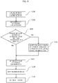
- FIG 4 is a diagram showing a flowchart of processing leading from determination of a formation configuration when linking trains to system activation. Redundant trunk transmission paths are provided as a multiplex system which may be the above duplex system.
- step 101 the integrated train control unit 5 serving as the master detects (acquires), from each of the respective trunk transmission paths in the multiplex system, the state of train formation linkage based on the states of connections of the electric couplers 11.
- step 102 the integrated train control unit 5 serving as the master recognizes the formation configuration based on the state of train formation linkage detected (acquired) from each of the respective trunk transmission paths in the multiplex system.
- step 103 the integrated train control unit 5 serving as the master determines whether or not the formation configurations recognized based on the respective trunk transmission paths in the multiplex system are identical.
- the integrated train control unit 5 serving as the master detects, in step 104, that the linkage parts of the trunk transmission paths have a fault and adopts the transmission path from which a formation configuration including a largest number of cars has been detected (that is, a transmission path regarded normal).
- step 105 the integrated train control unit 5 serving as the master determines, in cases where the determination result in step 103 has been YES, as final the recognized formation configuration as it is, or otherwise, determines as final the formation configuration including a largest number of cars as adopted in step 104, then distributes information on the determined formation configuration along with information on the traveling direction to each transmission terminal 6.
- each transmission terminal 6 having received the information on the determined formation configuration updates the information on the formation configuration managed and stored in the transmission terminal 6 itself, and sets IP addresses of the devices A to C connected to itself in the car where the transmission terminal 6 itself is mounted.
- step S107 When the IP addresses of all devices A to C included in the formation have been set, the system configured by the train formation is activated in step S107.
- Processing may be arranged such that, after system activation, the integrated train control unit 5 serving as the master informs that, as detected in the above step 104, the linkage parts of the trunk transmission paths have a fault to, for example, the driver by outputting a display to a monitor screen on the driver's platform.
- the transmission terminals 6 are each provided with a topology counter (not shown) and, when the information on the formation configuration is updated, the counter value before updating is retained. When the counter values before and after updating of the information on the formation configuration differ, the transmission terminals 6 keep blocking at formation boundaries (communication blocking between adjacent formations).
- the information on a state with a fault as described above (information on the formation configuration and topology counter values before and after information updating) is entirely cleared when the power supply is turned off and when formation disconnection or linkage is carried out.
Landscapes
- Engineering & Computer Science (AREA)
- Mechanical Engineering (AREA)
- Power Engineering (AREA)
- Transportation (AREA)
- Life Sciences & Earth Sciences (AREA)
- Sustainable Development (AREA)
- Sustainable Energy (AREA)
- Electric Propulsion And Braking For Vehicles (AREA)
- Small-Scale Networks (AREA)
Abstract
Description
- The present invention relates to a car information control system capable of meeting a situation where trains are linked or divided, too.
- A car information control system controls/monitors devices mounted on cars.
- In
patent literature 1, a technology is disclosed in which: between plural linked railway cars, plural transmission terminals respectively connected to a first and a second transmission path configuring a redundant system respectively monitor information transfers through the first and the second transmission path; normally, one of the transmission paths is used as valid with the other transmission path left unused as invalid; and, when a fault occurrence is detected in the one of the transmission paths, information transfers through the transmission path are treated as invalid, whereas the other transmission path is selected to enable valid information transfers. - In
patent literature 2, a technology is disclosed according to which, in a state where formations including train information management devices compatible with transmission protocols for cars based on different specifications (Ethernet (registered trade mark) protocol and ARCNET protocol) are mixed, when the formations are linked together, information complying with whichever protocol can be read in whichever formation. -
- Patent literature 1:
Japanese Unexamined Patent Application Publication No. 2013-126164 - Patent literature 2: International Publication No. 2014/188487
- In trunk transmission paths of a redundant duplex system, when, at a time of linking formations (at a time of changing a formation configuration), a fault (e.g., a disconnection) occurs in either system, the formation configurations recognized in a transmission path-1 system and in a transmission path-2 system become different. A problem is that, when this occurs, the formation configuration cannot be determined, so that car information control over the whole linked formations (controlling and monitoring of devices) is not possible and so that car operations are hampered.
- The present invention has been made in view of the above problem, and an object of the invention is to make it possible for a car information control system to recognize, even in a state where, with linked formations including cars having trunk transmission paths in a redundant duplex system, a fault exists in the trunk transmission path on one side in the system, a formation configuration including linked formations and perform car information control.
- To solve the above problem, the car information control system according to the present invention includes: transmission paths installed, in a redundant multiplex system, across plural cars configuring a formation; and integrated train control units and transmission terminals mounted on the cars and connected to the respective transmission paths in the redundant multiplex system. The integrated train control units execute processing: to recognize formation configurations information on which is obtained from the respective transmission paths; to adopt, when the formation configurations recognized in a state with the plural formations linked are identical between the respective transmission paths, the formation configurations, or, when the formation configurations are not identical between the respective transmission paths, to detect that the transmission paths in the redundant multiplex system have a fault and adopt a formation configuration including a largest number of cars; and to distribute information on the adopted formation configuration to the transmission terminals. The transmission terminals are connected with on-car devices mounted on the cars and allocate IP addresses to the on-car devices based on the information on the formation configuration received from the integrated train control units.
- According to the present invention, even in cases where, in a state with formations linked, information on formation linkage is transmitted only through a transmission path on one side in a redundant duplex system including trunk transmission paths, for example, due to a fault in an electric coupler of a car, it is possible to recognize the formation configuration including the trunk transmission paths linked in the redundant duplex system and perform car information control over the whole formation while retaining the transmission path redundancy.
-
- [
FIG. 1] Fig. 1 is a diagram showing a configuration example in a state with, in a linked formation including two formations, a trunk transmission path on one side in a redundant duplex system disconnected. - [
FIG. 2] FIG. 2 is a diagram showing a configuration example of a leading car. - [
FIG. 3] FIG. 3 is a diagram showing a configuration example of an intermediate car. - [
FIG. 4] FIG 4 is a diagram showing a flowchart of processing leading from determination of a formation configuration when linking trains to system activation. - In the following, as a form of implementing the present invention, an embodiment example will be described with reference to drawings. Though the present invention concerns, as trunk transmission paths, not only those in a redundant duplex system but also those in a redundant multiplex system, the following embodiment will be described as an example based on a redundant duplex system.
-
Fig. 1 is a diagram showing a configuration example in a state with, in a linked formation including a formation A and a formation B, atransmission path system 1 on one side in a redundant duplex system is disconnected. - The formation A and the formation B respectively include plural cars, for example, three cars as shown in
FIG. 1 . - One each of the integrated
train control units 5 configuring a car information control system is installed in a leadingcar 1 of each formation. In the case of the formations A and B shown inFIG. 1 , an integratedtrain control unit 1 is provided in each of thecars 1 that can be leading the train depending on traveling direction. -
Transmission terminals 6 included in the car information control system are installed to be in each car of each formation and in each trunk transmission path in the redundant duplex system. In the example shown inFIG. 1 , each of the leadingcars 1 andintermediate cars 2 is provided withtransmission terminals 6 to be in a transmission path-1system 3 and a transmission path-2system 4. - This configuration is maintained even when the number of cars included in each of the formation A and the formation B is increased or decreased.
- The integrated
train control unit 5 provided in each leadingcar 1 and thetransmission terminals 6 provided in each of the cars (1 and 2) are connected by trunk transmission paths (3 and 4) in a redundant duplex system, thereby enabling data transmission. -
FIG. 2 is a diagram showing a configuration example of a leadingcar 1. Thetransmission terminals 6 respectively connected to the transmission path-1system 3 and the transmission path-2system 4 are each connected with an integratedtrain control unit 5 besides being connected with devices A and B and also with, via aninterface conversion unit 7, device C, and, furthermore, with an electric coupler provided at a car head. - When formations are linked, out of the integrated
train control units 5 provided in the cars configuring the linked formation, one to be a master integratedtrain control unit 5 is determined. For example, the integratedtrain control unit 5 provided in the leadingcar 1 in the traveling direction of the linked formation is made a master. - The integrated
train control unit 5 made the master executes processing based on the flowchart shown inFIG. 4 being described later. The integratedtrain control units 5 other than the master can be made to operate to subsequently repeat distribution to eachtransmission terminal 6 of information on the formation configuration distributed from the master integratedtrain control unit 5 to eachtransmission terminal 6. -
FIG. 3 is a diagram showing a configuration example of anintermediate car 2. Thetransmission terminals 6 respectively connected to the transmission path-1system 3 and the transmission path-2system 4 are each connected with devices A and B and also with, via aninterface conversion unit 7, a device C. - As described above, the
transmission terminals 6 provided in each of the cars (1 and 2) are connected, either directly or via aninterface conversion unit 7, with devices A to C mounted on the cars and control/monitor car information. The devices A to C mounted on each of the cars (1 and 2) include, for example, a trunk controller, a security system, a drive system, a door control system, an in-car guidance system, and an automatic announcement system. Whether the connections of devices A to C to thetransmission terminals 6 are direct or via aninterface conversion unit 7 is determined appropriately depending on the condition of interface matching between the devices and thetransmission terminals 6. -
FIG 4 is a diagram showing a flowchart of processing leading from determination of a formation configuration when linking trains to system activation. Redundant trunk transmission paths are provided as a multiplex system which may be the above duplex system. - In step 101, the integrated
train control unit 5 serving as the master detects (acquires), from each of the respective trunk transmission paths in the multiplex system, the state of train formation linkage based on the states of connections of theelectric couplers 11. - In step 102, the integrated
train control unit 5 serving as the master recognizes the formation configuration based on the state of train formation linkage detected (acquired) from each of the respective trunk transmission paths in the multiplex system. - In step 103, the integrated
train control unit 5 serving as the master determines whether or not the formation configurations recognized based on the respective trunk transmission paths in the multiplex system are identical. - When determined not identical (No), the integrated
train control unit 5 serving as the master detects, instep 104, that the linkage parts of the trunk transmission paths have a fault and adopts the transmission path from which a formation configuration including a largest number of cars has been detected (that is, a transmission path regarded normal). - In
step 105, the integratedtrain control unit 5 serving as the master determines, in cases where the determination result in step 103 has been YES, as final the recognized formation configuration as it is, or otherwise, determines as final the formation configuration including a largest number of cars as adopted instep 104, then distributes information on the determined formation configuration along with information on the traveling direction to eachtransmission terminal 6. - In step 106, each
transmission terminal 6 having received the information on the determined formation configuration updates the information on the formation configuration managed and stored in thetransmission terminal 6 itself, and sets IP addresses of the devices A to C connected to itself in the car where thetransmission terminal 6 itself is mounted. - When the IP addresses of all devices A to C included in the formation have been set, the system configured by the train formation is activated in step S107.
- Processing may be arranged such that, after system activation, the integrated
train control unit 5 serving as the master informs that, as detected in theabove step 104, the linkage parts of the trunk transmission paths have a fault to, for example, the driver by outputting a display to a monitor screen on the driver's platform. - The
transmission terminals 6 are each provided with a topology counter (not shown) and, when the information on the formation configuration is updated, the counter value before updating is retained. When the counter values before and after updating of the information on the formation configuration differ, thetransmission terminals 6 keep blocking at formation boundaries (communication blocking between adjacent formations). - The information on a state with a fault as described above (information on the formation configuration and topology counter values before and after information updating) is entirely cleared when the power supply is turned off and when formation disconnection or linkage is carried out.
- As described above, according to the present embodiment, even in cases where, with formations linked, information on the linkage is transmitted only through a transmission path on one side in a redundant multiplex system including trunk transmission paths, it is possible to determine the formation configuration linked via the trunk transmission paths in the redundant multiplex system, set the IP addresses of all devices mounted on the cars included in the formation configuration and perform train information control for the whole formation.
- 1 ··· Leading car, 2 ··· Intermediate car, 3 ··· Transmission path-1 system, 4 ··· Transmission path-2 system, 5 ··· Integrated train control unit, 6 ··· Transmission terminal, 7 ··· Interface conversion unit, 8 ··· Device A, 9 ··· Device B, 10 ··· Device C, 11 ··· Electric coupler
Claims (4)
- A car information control system comprising:transmission paths installed, in a redundant multiplex system, across a plurality of cars configuring a formation, andintegrated train control units and transmission terminals mounted on the cars and connected to the respective transmission paths in the redundant multiplex system,wherein the integrated train control units execute processing:to recognize formation configurations information on which is obtained from the respective transmission paths;to adopt, when the formation configurations recognized in a state with a plurality of the formations linked are identical between the respective transmission paths, the formation configurations, or, when the formation configurations are not identical between the respective transmission paths, to detect that the transmission paths in the redundant multiplex system have a fault and adopt a formation configuration including a largest number of cars; andto distribute information on the adopted formation configuration to the transmission terminals,wherein the transmission terminals are connected with on-car devices mounted on the cars and allocate IP addresses to the on-car devices based on the information on the formation configuration received from the integrated train control units.
- The car information control system according to claim 1,
wherein the integrated train control units execute processing to distribute information including information on a travel direction to the transmission terminals. - The car information control system according to one of claims 1 and 2,
wherein the integrated train control units execute processing to notify of the fault detected in the transmission paths in the redundant multiplex system. - The car information control system according to one of claims 1 to 3,
wherein the processing for execution by the integrated train control units is executed by an integrated train control unit determined, when a plurality of the formations are linked, as a master.
Applications Claiming Priority (2)
| Application Number | Priority Date | Filing Date | Title |
|---|---|---|---|
| JP2019163167A JP7257922B2 (en) | 2019-09-06 | 2019-09-06 | Vehicle information control system |
| PCT/JP2020/026547 WO2021044725A1 (en) | 2019-09-06 | 2020-07-07 | Vehicle information control system |
Publications (2)
| Publication Number | Publication Date |
|---|---|
| EP4026721A1 true EP4026721A1 (en) | 2022-07-13 |
| EP4026721A4 EP4026721A4 (en) | 2023-09-27 |
Family
ID=74852634
Family Applications (1)
| Application Number | Title | Priority Date | Filing Date |
|---|---|---|---|
| EP20859663.5A Pending EP4026721A4 (en) | 2019-09-06 | 2020-07-07 | VEHICLE INFORMATION CONTROL SYSTEM |
Country Status (3)
| Country | Link |
|---|---|
| EP (1) | EP4026721A4 (en) |
| JP (1) | JP7257922B2 (en) |
| WO (1) | WO2021044725A1 (en) |
Families Citing this family (1)
| Publication number | Priority date | Publication date | Assignee | Title |
|---|---|---|---|---|
| CN115635990A (en) * | 2022-11-03 | 2023-01-24 | 通号城市轨道交通技术有限公司 | Vehicle-mounted operation control system based on head-to-tail redundancy |
Family Cites Families (6)
| Publication number | Priority date | Publication date | Assignee | Title |
|---|---|---|---|---|
| JP4358608B2 (en) * | 2003-11-25 | 2009-11-04 | 株式会社日立製作所 | Information transmission system and information transmission method |
| ES2384591T3 (en) * | 2007-12-06 | 2012-07-09 | Mitsubishi Electric Corporation | Communication device between train vehicles |
| JP5677244B2 (en) * | 2011-09-08 | 2015-02-25 | 三菱電機株式会社 | Train information management device |
| JP5520917B2 (en) * | 2011-11-09 | 2014-06-11 | 株式会社日立製作所 | Information transmission apparatus and information transmission method |
| JP5711653B2 (en) | 2011-12-15 | 2015-05-07 | 株式会社日立製作所 | Information transmission system and information transmission method |
| US9787542B2 (en) | 2013-05-20 | 2017-10-10 | Mitsubishi Electric Corporation | Train-information management device and train-information management method |
-
2019
- 2019-09-06 JP JP2019163167A patent/JP7257922B2/en active Active
-
2020
- 2020-07-07 EP EP20859663.5A patent/EP4026721A4/en active Pending
- 2020-07-07 WO PCT/JP2020/026547 patent/WO2021044725A1/en not_active Ceased
Also Published As
| Publication number | Publication date |
|---|---|
| WO2021044725A1 (en) | 2021-03-11 |
| JP7257922B2 (en) | 2023-04-14 |
| EP4026721A4 (en) | 2023-09-27 |
| JP2021044617A (en) | 2021-03-18 |
Similar Documents
| Publication | Publication Date | Title |
|---|---|---|
| RU2563095C2 (en) | Method and device to control operating condition of coupling device | |
| CN103825791B (en) | Method for controlling parallel redundancy of MVB master | |
| US10700889B2 (en) | Ring network for a vehicle | |
| EP2999164B1 (en) | System and vehicle for detecting malfunctioning communication apparatus | |
| US9994241B2 (en) | Rail vehicle | |
| EP2705994A1 (en) | Control arrangement for a rail vehicle | |
| WO2020057934A1 (en) | Vehicle control system | |
| CN101638099A (en) | System and method for brake system control in distributed power vehicles | |
| JP7298015B2 (en) | Train door logic smart control system based on smart control unit | |
| CN1597408A (en) | Data transmission system, and method of transmitting data from a central station to a track-bound vehicle | |
| US9787542B2 (en) | Train-information management device and train-information management method | |
| US20180170412A1 (en) | Control arrangement for a vehicle | |
| EP4026721A1 (en) | Vehicle information control system | |
| EP3853089B1 (en) | Brake redundancy in a locomotive consist | |
| JP6091385B2 (en) | Train radio system | |
| CN114750803B (en) | Direction control system, method and vehicle during rail transit vehicle operation | |
| CN108995663B (en) | Apparatus and method for switching a zero-speed circuit, and a rail vehicle having the same | |
| JP4339067B2 (en) | Railway vehicle communication equipment | |
| CN112744266B (en) | Central control method, device and control system for train operation | |
| CN109691018B (en) | System for energy and/or data transmission | |
| JP6608337B2 (en) | Wireless communication system | |
| KR102682201B1 (en) | Locomotive-to-car communication system for freight trains and method of implementing network protocol for the system | |
| CN105917616B (en) | Communication device, train network system, and network setting method | |
| CN102314174B (en) | For the Modular control system of electric auxiliary auxiliary system | |
| EP3118052B1 (en) | Train information management device |
Legal Events
| Date | Code | Title | Description |
|---|---|---|---|
| STAA | Information on the status of an ep patent application or granted ep patent |
Free format text: STATUS: THE INTERNATIONAL PUBLICATION HAS BEEN MADE |
|
| PUAI | Public reference made under article 153(3) epc to a published international application that has entered the european phase |
Free format text: ORIGINAL CODE: 0009012 |
|
| STAA | Information on the status of an ep patent application or granted ep patent |
Free format text: STATUS: REQUEST FOR EXAMINATION WAS MADE |
|
| 17P | Request for examination filed |
Effective date: 20220329 |
|
| AK | Designated contracting states |
Kind code of ref document: A1 Designated state(s): AL AT BE BG CH CY CZ DE DK EE ES FI FR GB GR HR HU IE IS IT LI LT LU LV MC MK MT NL NO PL PT RO RS SE SI SK SM TR |
|
| DAV | Request for validation of the european patent (deleted) | ||
| DAX | Request for extension of the european patent (deleted) | ||
| A4 | Supplementary search report drawn up and despatched |
Effective date: 20230825 |
|
| RIC1 | Information provided on ipc code assigned before grant |
Ipc: B61L 25/02 20060101ALI20230821BHEP Ipc: B61L 15/00 20060101ALI20230821BHEP Ipc: H04L 12/28 20060101ALI20230821BHEP Ipc: B60L 15/42 20060101AFI20230821BHEP |