EP4026671B1 - Utility knife - Google Patents
Utility knife Download PDFInfo
- Publication number
- EP4026671B1 EP4026671B1 EP21201310.6A EP21201310A EP4026671B1 EP 4026671 B1 EP4026671 B1 EP 4026671B1 EP 21201310 A EP21201310 A EP 21201310A EP 4026671 B1 EP4026671 B1 EP 4026671B1
- Authority
- EP
- European Patent Office
- Prior art keywords
- collet
- slot
- blade
- sleeve
- handle
- Prior art date
- Legal status (The legal status is an assumption and is not a legal conclusion. Google has not performed a legal analysis and makes no representation as to the accuracy of the status listed.)
- Active
Links
Images


Classifications
-
- B—PERFORMING OPERATIONS; TRANSPORTING
- B26—HAND CUTTING TOOLS; CUTTING; SEVERING
- B26B—HAND-HELD CUTTING TOOLS NOT OTHERWISE PROVIDED FOR
- B26B5/00—Hand knives with one or more detachable blades
-
- B—PERFORMING OPERATIONS; TRANSPORTING
- B25—HAND TOOLS; PORTABLE POWER-DRIVEN TOOLS; MANIPULATORS
- B25G—HANDLES FOR HAND IMPLEMENTS
- B25G3/00—Attaching handles to the implements
- B25G3/02—Socket, tang, or like fixings
- B25G3/12—Locking and securing devices
- B25G3/20—Locking and securing devices comprising clamping or contracting means acting concentrically on the handle or socket
- B25G3/22—Chucks
Definitions
- the present disclosure relates to utility knives. More particularly, the present disclosure relates to a blade holding device for a utility knife.
- GB 2 063 140 represents the closest prior art and discusses a utility knife.
- US 2,250,237 ; US 4,817,284 ; US 2008/110033 ; US 5,782,853 and US 5,657,541 provide further relevant information.
- a utility knife in one independent aspect, includes a handle having a body and a receiving aperture, a collet at least partially receivable in the receiving aperture, and a sleeve engageable with and surrounding the collet.
- the collet has a first end and a second end.
- the first end of the collet includes a first slot and a second slot formed therein.
- the first slot has a first dimension and the second slot has a second dimension different than the first dimension.
- the collet is configured to alternately receive one of a portion of a blade of a first type in the first slot and a portion of a blade of a second type in the second slot.
- the sleeve and the collet are co-rotatable relative the handle to move the collet to a secured position in which one of the blade of the first type and the blade of the second type are secured to the collet.
- a cross-section of a portion of the collet is elliptical.
- FIGS. 1A and 1B illustrate a utility knife 10 according to an exemplary embodiment.
- the utility knife 10 includes a handle 14, a blade 18, and a blade holding mechanism or chuck 22.
- the handle 14 which is graspable by a user, has a body 24 elongated along an axis A1 that defines an internal storage space 25 therein.
- the handle 14 further supports an end cover or cap 26 that is removably coupled to an end of the body 24.
- the cap 26 is a threaded end cap 26 that is threadable onto or into the body 24, and at least a portion of the cap 26 is hollow such that, when the cap 26 is attached to the body 24, the void 25 extends into the cap 26.
- the cap 26 is disposed at one end (e.g., a rear end) of the utility knife 10, opposite an end on which the chuck 22 is supported (e.g., a front end of the knife 10).
- a threadable cap 26 is shown in the illustrated embodiment, non-threaded caps are also contemplated.
- the chuck 22 is capable of selectively supporting any one of multiple different types of blades (e.g., differently sized blades, differently dimensioned blades, blades having different blade shapes or geometries, and/or the like) and retains each blade 18 in a manner suitable for using the knife 10 in a cutting operation.
- the illustrated utility knife 10 is configured to alternately receive any one of the variety of blades in the chuck 22 depending on a desired cutting application/operation.
- the illustrated utility knife 10 is further configured to store the variety of blades in the storage space 25 when not in use.
- the chuck 22 may be caused to rotate to secure the blade 18 against movement relative to the chuck 22 to perform a cutting operation.
- the chuck 22 includes a collet 28 and a spindle or sleeve 30 that cooperate to selectively secure the blade 18 to the chuck 22.
- the sleeve 30 includes a gripping surface or texture(e.g., on an outer surface) and may include or be formed from a gripping material.
- the sleeve 30 may have a polygonal shape; for example, in the illustrated embodiment, the sleeve 30 is generally triangular; in other embodiments, the sleeve may be hexagonal, heptagonal, etc.
- the collet 28 is positioned within a channel 34 of the sleeve 30.
- a first end 28a of the collet 28 may engage and supports the blade 18, and a second end 28b of the collet 28 may engage the handle 14.
- the second end includes a threaded shank or stem 36 having threads 36a that are configured to engage corresponding threads 36b on an inner surface of the handle 14 (e.g., within a receiving aperture 27 of the handle 14).
- the first end 28a of the collet 28 includes a plurality of slots such as a first slot 38 having a first dimension (e.g., a first length L1 and/or a first width W1), and a second slot 42 having a second dimension (e.g., a second length L2 and/or a second width W2) that is different from the first dimension.
- the first slot 38 and the second slot 42 may have different dimension(s) and/or be configured to alternately accommodate blades that have different sizes and/or shapes, such as at least a first blade 18a and a second blade 18b.
- the first slot 38 and the second slot 42 may intersect one another.
- Non-intersecting slots e.g., parallel slots and/or the like are also contemplated.
- the collet 28 may rotate along with the sleeve 30 due to a generally non-circular (e.g., elliptical) geometry 33 ( FIG. 2 ) shared by the collet 28 and the sleeve 30.
- a generally non-circular (e.g., elliptical) geometry 33 FIG. 2
- the threads 36a of the collet 28 may engage the threads 36b in the receiving aperture 27 of the handle 14 to thereby axially move the collet 28 toward a first or clamped position (e.g., toward the handle 14).
- the collet 28 and sleeve 30 can be rotatable relative the handle 14 in a first rotational direction R1 (e.g., a clockwise "CW” direction) to draw or thread the shank 36 further into the aperture 27 and the collet 28 and sleeve 30 can be rotatable relative the handle 14 in a second rotational direction (e.g., a counter clockwise "CCW” direction) to unthread or retract the shank 36 from the aperture 27.
- R1 e.g., a clockwise "CW” direction
- CW clockwise "CW" direction
- the collet 28 may move along the axis A1 in a first direction D1.
- the collet 28 may move along the axis A1 in a second direction, which may be generally opposite the first direction D1.
- the non-circular geometry 33 inhibits relative rotational motion between the collet 28 and the sleeve 30.
- a cross-section of an outer face of the collet 28 and the channel 34 or another inner face of the sleeve 30 are substantially elliptical or ovular.
- the non-circular geometry 33 may have a different profile.
- the cross-section may be circular and/or the collet and/or sleeve may include one or more features to inhibit relative rotation, such as a lug, key, or the like.
- the collet 28 further includes a body 44 formed between the ends 28a, 28b of the collet 28.
- the body 44 includes the truncated stem 36 and has a first cross-sectional width (e.g., first circumference).
- a head 45 is formed on the collet 28 adjacent the first end 28a and has a second circumference that is greater than the first circumference.
- the head 45 is "bulbed" shaped and/or tapered outwardly such that the body 44 transitions into the head 45.
- the head 45 may be complemented by an oppositely tapered and/or flared face 46 of the sleeve 30. In other words, the head 45 may be enlarged relative to the body 44, and an outer surface of the head 45 engages a portion of the sleeve 30.
- the sleeve 30 further includes a stop surface or ring 48 that may bear and/or slip against the handle 14 such that the collet 28 is secured (e.g., pinned, trapped, stopped, and/or the like) by the flared face 46 at one end as the chuck 22 is rotated to draw the collet 28 toward the handle 14.
- the stop ring 48 abuts against a stop surface 50 formed on, at, about, and/or proximate to an opening 54 of the receiving aperture 27 to pin the sleeve 30 in position between the head 45 and the handle 14.
- the flared face 46 of the sleeve 30 exerts a force (e.g., a compressive force) on the head 45 adjacent the first end 28a of the collet 28, which causes the portions of the collet 28 to move radially inwardly, compressing the slots 38, 42.
- a force e.g., a compressive force
- the portions of the collet 28 may move radially outwardly, decompressing the head 45 and enlarging the slots 38, 42.
- Each slot 38, 42 is configured to receive an offset anchor 58, tang, and/or the like of a given range of blade sizes.
- the first slot 38 may be shaped and/or sized to receive a first blade 18a (e.g., a number 2 blade or "#2 blade" - FIGS. 4B and 5 ), and the second slot 42 may be shaped and/or sized to receive a second blade 18b (e.g., a number 11 blade or "#11 blade” - FIGS. 4C , 4D, and 5 ). Therefore, a #2 blade 18a can be positioned in the first slot 38, or a #11 blade 18b can be positioned in the second slot 42 of the collet 28 depending on the needs of the user. In some embodiments, the collet 28 may receive blades of additional or alternative sizes.
- the tang 58 of each blade 18a, 18b can include a tang length TL and a tang width TW.
- the tang width TW may be the same or similar as a width of a cutting part of the blade 18, the tang width TW could also be different than the width of the cutting part of the blade 18.
- the tang length TL and tang width TW of the #11 blade 18b are less than that of the #2 blade 18a. Accordingly, the length and width of the slots 38, 42 may be sized to correspond to the length and width of the different blades.
- first length L1 and first width W1 of the first slot 38 are suitable to receive the tang 58 of the #2 blade 18a
- the second length L2 and second width W2 of the second slot 42 are suitable to receive the tang 58 of the #11 blade 18b.
- Rotation of the chuck 22 relative the handle 14 alters the width of the slots 38, 42 to thereby clamp the collet 28 down on to the tang 58 of whichever blade 18 is received in the slot 38, 42.
- the first length L1 of the first slot 38 and the second length L2 of the second slot 42 extend though the axis A1, which in the illustrated embodiment represents a longitudinal axis the utility knife 10.
- the slots 38, 42 may optionally intersect to form a cross or "X" through a middle of the collet 28.
- the first slot 38 extends along a major axis MA (e.g., long axis, major diameter, etc.) of an elliptical part of the collet 28 and into the stem body 44 through the head 45.
- the second slot 42 extends along a minor axis mA (e.g., short axis, minor diameter, etc.) of the elliptical part of the collet 28 and into the stem body 44 through the head 45.
- a minor axis mA e.g., short axis, minor diameter, etc.
- the blade 18 is positioned within the corresponding slot (e.g., first slot 38, second slot 42).
- the chuck 22 is rotated relative the handle 14 to cause the sleeve 30 to compress the head 45 of the collet 28 (e.g., radially inwardly) toward a blade holding or clamped position, which thereby reduces the width (e.g., first width W 1, second width W2) of both slots 38, 42 and secures the blade 18 to the knife 10.
- the first blade 18a, second blade 18b, and other blades are selectively interchangeable and useable with the same knife 10 and collet 28.
- the threads 36a, 36b engage to draw the collet 28 into the handle 14.
- the enlarged head 45 will be squeezed by the sleeve 30 to push the slots 38, 42 closed (e.g., toward a clamped or secured position) around the desired blade placed therebetween.
- FIGS. 7A-7C illustrate a utility knife 100 according to another embodiment.
- the utility knife 100 of FIGS. 7A-7C is similar to the utility knife 10 described above with reference to FIGS. 1A-6 , and similar features are identified with similar reference numbers, plus "100.” Some similarities and differences between the knife 100 and the knife 10 are described below.
- the utility knife 100 includes a handle 114 and a chuck 122 that removably accepts a variety of blades 18. As described above, portions of the chuck 122 may be caused to rotate and, thus, secure the blades 18 within the chuck 122 to perform a cutting operation.
- the utility knife 100 further includes a cap 126 removably coupled to a body 124 of the handle 114 to store one or more blades 18 in a storage space 125 ( FIG. 7B ) of the knife 100.
- the chuck 122 includes a collet 128 and a sleeve 130 that are operable to retain the blades 18.
- the sleeve 130 of the utility knife 100 may be polygonal and may include additional gripping edges or surfaces.
- the sleeve may have an overall hexagonal cross-section.
- the sleeve 130 has more than six sides, such as eight sides, ten sides, or twelve sides.
- the collet 128 includes at least a third slot 143 in addition to a first slot 138 and a second slot 142.
- the third slot 143 is configured, just as the other slots 138, 142, to alternately receive a blade 18. Although three slots are shown for in the illustrated embodiment, more than three slots may be provided.
- the third slot 143 may have a third dimension (e.g., a third length and/or a third width) that is different from the length and width of the first slot 138 and/or the second slot 142.
- the third slot 143 may be configured to receive a blade 18 smaller than the first blade 18a, such as an extra fine or extra exact blade 18c that is smaller than the #2 blade 18a and #11 blade 18b.
- the third slot 143 allows a user to alternately secure the tang 58 of a third blade 18c (e.g. extra fine blade) to the knife 100.
- the third slot 143 may operate in the same or similar manner to the slots described above. Either utility knife 10, 100 could include a collet 28, 128 having a different number of slots.
- the collet 128 includes a tapered head 145 that is partially surrounded and engaged by a bushing 155 at one end. An opposing end of the bushing 155 is supported directly in a channel 134 formed in the sleeve 130. The bushing 155 accommodates contact between the collet 128 and the sleeve 130.
- FIGS. 7A-7C Yet another difference between the utility knife 10 and the utility knife 100 is illustrated in FIGS. 7A-7C . Similar to the stop surface 50 described above, the collet 128 is threaded into a receiving aperture 127 in the handle 114 to abut the sleeve 130 against a stop bearing 150 supported on the handle 114. Just as the stop surface 50 constrains the sleeve 30 between the head 45 and the handle 14, the stop bearing 150 constrains the sleeve 130 between the bulbed head 145 and the handle 114.
- FIG. 7C further illustrates a protective cap that is received on the knife 100.
- a protective cap that is received on the knife 100.
- each embodiment discussed herein could include the same or a similar cap.
- the provision of multiple slots in a single collet provides a larger clamping force exerted on a blade received in one of the slots compared to the clamping force exerted on a blade received in a collet having a single slot.
Landscapes
- Engineering & Computer Science (AREA)
- Mechanical Engineering (AREA)
- Life Sciences & Earth Sciences (AREA)
- Forests & Forestry (AREA)
- Knives (AREA)
Description
- This application claims priority to co-pending
U.S. Provisional Patent Application No. 63/088,144, filed October 6, 2020 - The present disclosure relates to utility knives. More particularly, the present disclosure relates to a blade holding device for a utility knife.
GB 2 063 140 US 2,250,237 ;US 4,817,284 ;US 2008/110033 ;US 5,782,853 andUS 5,657,541 provide further relevant information. - In one independent aspect, a utility knife includes a handle having a body and a receiving aperture, a collet at least partially receivable in the receiving aperture, and a sleeve engageable with and surrounding the collet. The collet has a first end and a second end. The first end of the collet includes a first slot and a second slot formed therein. The first slot has a first dimension and the second slot has a second dimension different than the first dimension. The collet is configured to alternately receive one of a portion of a blade of a first type in the first slot and a portion of a blade of a second type in the second slot. The sleeve and the collet are co-rotatable relative the handle to move the collet to a secured position in which one of the blade of the first type and the blade of the second type are secured to the collet. A cross-section of a portion of the collet is elliptical.
- Other aspects will become apparent by consideration of the detailed description and accompanying drawings.
-
-
FIG. 1A is a perspective view of a utility knife according to one embodiment. -
FIG. 1B is a cross-sectional view of the utility knife ofFIG. 1A , viewed alongsection 1B-1B. -
FIG. 2 is a perspective view of a collet of the utility knife ofFIG. 1A . -
FIG. 3 is a perspective cross-sectional view of a portion of the collet ofFIG. 2 , viewed along section 3-3. -
FIGS. 4A-4D are enlarged perspective views of a collet supporting different blades. -
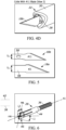
FIG. 5 is a side view of different types of blades. -
FIG. 6 is a perspective view of the collet ofFIG. 2 , illustrating blade receiving slots. -
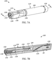
FIG. 7A is a perspective view of a utility knife according to another embodiment. -
FIG. 7B is a cross-sectional view of the utility knife ofFIG. 7A viewed alongsection 7B-7B. -
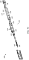
FIG. 7C is a partially exploded perspective view ofFIG. 7B , additionally illustrating a cap. -
FIGS. 1A and 1B illustrate autility knife 10 according to an exemplary embodiment. Theutility knife 10 includes ahandle 14, ablade 18, and a blade holding mechanism orchuck 22. Shown particularly inFIG. 1B , thehandle 14, which is graspable by a user, has abody 24 elongated along an axis A1 that defines aninternal storage space 25 therein. Thehandle 14 further supports an end cover orcap 26 that is removably coupled to an end of thebody 24. In the illustrated embodiment, thecap 26 is athreaded end cap 26 that is threadable onto or into thebody 24, and at least a portion of thecap 26 is hollow such that, when thecap 26 is attached to thebody 24, thevoid 25 extends into thecap 26. In the illustrated embodiment, thecap 26 is disposed at one end (e.g., a rear end) of theutility knife 10, opposite an end on which thechuck 22 is supported (e.g., a front end of the knife 10). Although athreadable cap 26 is shown in the illustrated embodiment, non-threaded caps are also contemplated. - The
chuck 22 is capable of selectively supporting any one of multiple different types of blades (e.g., differently sized blades, differently dimensioned blades, blades having different blade shapes or geometries, and/or the like) and retains eachblade 18 in a manner suitable for using theknife 10 in a cutting operation. The illustratedutility knife 10 is configured to alternately receive any one of the variety of blades in thechuck 22 depending on a desired cutting application/operation. The illustratedutility knife 10 is further configured to store the variety of blades in thestorage space 25 when not in use. - Portions of the
chuck 22 may be caused to rotate to secure theblade 18 against movement relative to thechuck 22 to perform a cutting operation. As shown inFIG. 1B , thechuck 22 includes acollet 28 and a spindle orsleeve 30 that cooperate to selectively secure theblade 18 to thechuck 22. In the illustrated embodiment, thesleeve 30 includes a gripping surface or texture(e.g., on an outer surface) and may include or be formed from a gripping material. Additionally, thesleeve 30 may have a polygonal shape; for example, in the illustrated embodiment, thesleeve 30 is generally triangular; in other embodiments, the sleeve may be hexagonal, heptagonal, etc. - With reference to
FIGS. 1B and3 , thecollet 28 is positioned within achannel 34 of thesleeve 30. Afirst end 28a of thecollet 28 may engage and supports theblade 18, and asecond end 28b of thecollet 28 may engage thehandle 14. In the illustrated embodiment, the second end includes a threaded shank orstem 36 havingthreads 36a that are configured to engagecorresponding threads 36b on an inner surface of the handle 14 (e.g., within areceiving aperture 27 of the handle 14). - The
first end 28a of thecollet 28 includes a plurality of slots such as afirst slot 38 having a first dimension (e.g., a first length L1 and/or a first width W1), and asecond slot 42 having a second dimension (e.g., a second length L2 and/or a second width W2) that is different from the first dimension. As described in greater detail below, thefirst slot 38 and thesecond slot 42 may have different dimension(s) and/or be configured to alternately accommodate blades that have different sizes and/or shapes, such as at least afirst blade 18a and asecond blade 18b. In the illustrated embodiment, thefirst slot 38 and thesecond slot 42 may intersect one another. Non-intersecting slots (e.g., parallel slots and/or the like) are also contemplated. - When the
sleeve 30 is actuated (e.g., rotated, twisted, and/or the like), thecollet 28 may rotate along with thesleeve 30 due to a generally non-circular (e.g., elliptical) geometry 33 (FIG. 2 ) shared by thecollet 28 and thesleeve 30. As thesleeve 30 is rotated in a first direction R1, thethreads 36a of thecollet 28 may engage thethreads 36b in the receivingaperture 27 of thehandle 14 to thereby axially move thecollet 28 toward a first or clamped position (e.g., toward the handle 14). Stated another way, thecollet 28 andsleeve 30 can be rotatable relative thehandle 14 in a first rotational direction R1 (e.g., a clockwise "CW" direction) to draw or thread theshank 36 further into theaperture 27 and thecollet 28 andsleeve 30 can be rotatable relative thehandle 14 in a second rotational direction (e.g., a counter clockwise "CCW" direction) to unthread or retract theshank 36 from theaperture 27. In this way, the first width W1 and the second width W2 may be reduced as thecollet 28 is drawn into and/or closer to thehandle 14 to thereby clamp down on theblade 18 for holding the blade stationary during a cutting operation. - Referring to
FIGS. 2 and 3 , as thechuck 22 is rotated in the first direction R1, thecollet 28 may move along the axis A1 in a first direction D1. As thechuck 22 is rotated in a second direction, which may be generally opposite the first direction R1, thecollet 28 may move along the axis A1 in a second direction, which may be generally opposite the first direction D1. Thenon-circular geometry 33 inhibits relative rotational motion between thecollet 28 and thesleeve 30. In the illustrated embodiment, a cross-section of an outer face of thecollet 28 and thechannel 34 or another inner face of thesleeve 30 are substantially elliptical or ovular. In other embodiments, thenon-circular geometry 33 may have a different profile. In other embodiments, the cross-section may be circular and/or the collet and/or sleeve may include one or more features to inhibit relative rotation, such as a lug, key, or the like. - Referring still to
FIGS. 2 and 3 , thecollet 28 further includes abody 44 formed between theends collet 28. In the illustrated embodiment, thebody 44 includes thetruncated stem 36 and has a first cross-sectional width (e.g., first circumference). Ahead 45 is formed on thecollet 28 adjacent thefirst end 28a and has a second circumference that is greater than the first circumference. As best illustrated inFIG. 3 , thehead 45 is "bulbed" shaped and/or tapered outwardly such that thebody 44 transitions into thehead 45. Thehead 45 may be complemented by an oppositely tapered and/or flaredface 46 of thesleeve 30. In other words, thehead 45 may be enlarged relative to thebody 44, and an outer surface of thehead 45 engages a portion of thesleeve 30. - As illustrated in
FIGS. 1B and3 , thesleeve 30 further includes a stop surface orring 48 that may bear and/or slip against thehandle 14 such that thecollet 28 is secured (e.g., pinned, trapped, stopped, and/or the like) by the flaredface 46 at one end as thechuck 22 is rotated to draw thecollet 28 toward thehandle 14. Thestop ring 48 abuts against astop surface 50 formed on, at, about, and/or proximate to anopening 54 of the receivingaperture 27 to pin thesleeve 30 in position between thehead 45 and thehandle 14. - With reference to
FIGS. 2-5 , as thecollet 28 moves in the first direction D1 (e.g., toward thehandle 14 and further into the aperture 27), the flaredface 46 of thesleeve 30 exerts a force (e.g., a compressive force) on thehead 45 adjacent thefirst end 28a of thecollet 28, which causes the portions of thecollet 28 to move radially inwardly, compressing theslots collet 28 moves in the second direction D2, the portions of thecollet 28 may move radially outwardly, decompressing thehead 45 and enlarging theslots - Each
slot anchor 58, tang, and/or the like of a given range of blade sizes. For example, thefirst slot 38 may be shaped and/or sized to receive afirst blade 18a (e.g., anumber 2 blade or "#2 blade" -FIGS. 4B and5 ), and thesecond slot 42 may be shaped and/or sized to receive asecond blade 18b (e.g., anumber 11 blade or "#11 blade" -FIGS. 4C ,4D, and 5 ). Therefore, a #2blade 18a can be positioned in thefirst slot 38, or a #11blade 18b can be positioned in thesecond slot 42 of thecollet 28 depending on the needs of the user. In some embodiments, thecollet 28 may receive blades of additional or alternative sizes. - As best illustrated in
FIGS. 4B-4D , and5 , thetang 58 of eachblade blade 18, the tang width TW could also be different than the width of the cutting part of theblade 18. In some embodiments, the tang length TL and tang width TW of the #11blade 18b are less than that of the #2blade 18a. Accordingly, the length and width of theslots first slot 38 are suitable to receive thetang 58 of the #2blade 18a, and the second length L2 and second width W2 of thesecond slot 42 are suitable to receive thetang 58 of the #11blade 18b. Rotation of thechuck 22 relative thehandle 14 alters the width of theslots collet 28 down on to thetang 58 of whicheverblade 18 is received in theslot - Referring now to
FIG. 6 , the first length L1 of thefirst slot 38 and the second length L2 of thesecond slot 42 extend though the axis A1, which in the illustrated embodiment represents a longitudinal axis theutility knife 10. Theslots collet 28. In the illustrated embodiment, thefirst slot 38 extends along a major axis MA (e.g., long axis, major diameter, etc.) of an elliptical part of thecollet 28 and into thestem body 44 through thehead 45. Similarly, thesecond slot 42 extends along a minor axis mA (e.g., short axis, minor diameter, etc.) of the elliptical part of thecollet 28 and into thestem body 44 through thehead 45. Stated another way, the first length L1 is oriented parallel to the major axis MA, and the second length L2 is oriented parallel to the minor axis mA. - During installation of a desired blade (e.g., #2
blade 18a, #11blade 18b, etc.), theblade 18 is positioned within the corresponding slot (e.g.,first slot 38, second slot 42). Thechuck 22 is rotated relative thehandle 14 to cause thesleeve 30 to compress thehead 45 of the collet 28 (e.g., radially inwardly) toward a blade holding or clamped position, which thereby reduces the width (e.g., first width W 1, second width W2) of bothslots blade 18 to theknife 10. Thus, thefirst blade 18a,second blade 18b, and other blades are selectively interchangeable and useable with thesame knife 10 andcollet 28. More simply, when thechuck 22 is twisted in the first rotational direction R1 relative thehandle 14, thethreads collet 28 into thehandle 14. As thecollet 28 is drawn into thehandle 14, theenlarged head 45 will be squeezed by thesleeve 30 to push theslots -
FIGS. 7A-7C illustrate autility knife 100 according to another embodiment. Theutility knife 100 ofFIGS. 7A-7C is similar to theutility knife 10 described above with reference toFIGS. 1A-6 , and similar features are identified with similar reference numbers, plus "100." Some similarities and differences between theknife 100 and theknife 10 are described below. - The
utility knife 100 includes ahandle 114 and achuck 122 that removably accepts a variety ofblades 18. As described above, portions of thechuck 122 may be caused to rotate and, thus, secure theblades 18 within thechuck 122 to perform a cutting operation. Theutility knife 100 further includes acap 126 removably coupled to abody 124 of thehandle 114 to store one ormore blades 18 in a storage space 125 (FIG. 7B ) of theknife 100. In the illustrated embodiment ofFIGS. 7A-7C , thechuck 122 includes acollet 128 and asleeve 130 that are operable to retain theblades 18. - Some differences between the
utility knife 10 and theutility knife 100 are now described with reference toFIGS. 7B and7C . - Specifically, with reference to
FIG. 7B , thesleeve 130 of theutility knife 100 may be polygonal and may include additional gripping edges or surfaces. In the illustrated embodiment, for example, the sleeve may have an overall hexagonal cross-section. In some embodiments, thesleeve 130 has more than six sides, such as eight sides, ten sides, or twelve sides. With continued reference toFIG. 7B , thecollet 128 includes at least athird slot 143 in addition to afirst slot 138 and asecond slot 142. Thethird slot 143 is configured, just as theother slots blade 18. Although three slots are shown for in the illustrated embodiment, more than three slots may be provided. - As illustrated in
FIG. 7C , thethird slot 143 may have a third dimension (e.g., a third length and/or a third width) that is different from the length and width of thefirst slot 138 and/or thesecond slot 142. For example, thethird slot 143 may be configured to receive ablade 18 smaller than thefirst blade 18a, such as an extra fine or extraexact blade 18c that is smaller than the #2blade 18a and #11blade 18b. Stated another way, thethird slot 143 allows a user to alternately secure thetang 58 of athird blade 18c (e.g. extra fine blade) to theknife 100. Thethird slot 143 may operate in the same or similar manner to the slots described above. Eitherutility knife collet - As shown in
FIGS. 7A-7C . Similar to the tapered orbulbed head 45 described above, thecollet 128 includes a taperedhead 145 that is partially surrounded and engaged by abushing 155 at one end. An opposing end of thebushing 155 is supported directly in achannel 134 formed in thesleeve 130. Thebushing 155 accommodates contact between thecollet 128 and thesleeve 130. - Yet another difference between the
utility knife 10 and theutility knife 100 is illustrated inFIGS. 7A-7C . Similar to thestop surface 50 described above, thecollet 128 is threaded into a receivingaperture 127 in thehandle 114 to abut thesleeve 130 against a stop bearing 150 supported on thehandle 114. Just as thestop surface 50 constrains thesleeve 30 between thehead 45 and thehandle 14, the stop bearing 150 constrains thesleeve 130 between thebulbed head 145 and thehandle 114. -
FIG. 7C further illustrates a protective cap that is received on theknife 100. For clarity, each embodiment discussed herein could include the same or a similar cap. - It should be understood that, for some embodiments discussed herein, the provision of multiple slots in a single collet provides a larger clamping force exerted on a blade received in one of the slots compared to the clamping force exerted on a blade received in a collet having a single slot.
- Although the disclosure has been described in detail with reference to certain preferred embodiments, variations and modifications exist within the scope of one or more independent aspects as described. The invention is described by the attached claims.
Claims (13)
- A utility knife (10) comprising:a handle (14) having a body (24) and a receiving aperture;a collet (28) at least partially receivable in the receiving aperture, the collet having a first end (28a) and a second end (28b), the first end of the collet including a first slot (38) and a second slot (42) formed therein, the first slot having a first dimension and the second slot having a second dimension different from the first dimension, the collet configured to alternately receive one of a portion of a blade of a first type (18a) in the first slot and a portion of a blade of a second type (18b) in the second slot; anda sleeve (30) engageable with and surrounding the collet, the sleeve and the collet being co-rotatable relative the handle to move the collet to a secured position in which one of the blade of the first type and the blade of the second type are secured to the collet,wherein a cross-section of a portion of the collet is elliptical.
- The utility knife of claim 1, wherein the body includes an internal space (25) for storing at least one blade that is not in use, and wherein the utility knife further comprises an end cap (26) removably coupled to the body to selectively cover the internal space.
- The utility knife of claim 1, wherein the second end of the collet is threadably coupled to the handle, wherein the sleeve and collet are rotatable together about an axis and the collet is moveable along the axis relative the sleeve, and wherein rotation of the sleeve threads the collet further into the receiving aperture along the axis.
- The utility knife of claim 3, wherein the collet includes an enlarged portion (45) adjacent the first end.
- The utility knife of claim 4, wherein the handle includes a stop surface (50) formed at an opening of the receiving aperture, and wherein threading the collet further into the receiving aperture brings the enlarged portion toward the handle to abut the sleeve against the stop surface.
- The utility knife of claim 1, wherein the first dimension and the second dimension are reduced as the collet is threaded further into the receiving aperture.
- The utility knife of claim 1, wherein a cross-section of a portion of the sleeve is polygonal.
- The utility knife of claim 1, wherein the collet further includes a third slot (143) formed therein, the third slot having a third dimension different than the first dimension and the second dimension, wherein the third slot is configured to selectively receive a portion of a blade of a third type (18c), and wherein the collet and the sleeve are co-rotatable relative the handle to alter the third dimension.
- The utility knife (10) of claim 1 wherein:the collet (28) extends along an axis (A1), the collet including,a body (44) having a first width,a head (45) having a second width greater than the first width,the first slot (38) extending along the axis into the head, the first dimension of the first slot having a first length (L1),the second slot (42) extending along the axis into the head, the second slot intersecting the first slot and the second dimension is a second length (L2), the first slot and the second slot each configured to receive the different type of blade each having tangs with different lengths, andthe receiving aperture has a threaded shank (36);the sleeve (30) partially surrounding the head of the collet, rotation of the sleeve causing movement of the collet relative to the knife handle in a direction parallel to the axis, the sleeve movable between a release position and a blade holding position, the sleeve compressing the head while in the blade holding position to retain a blade positioned in one of the first slot and the second slot; andthe knife handle (14) being configured to receive the threaded shank,characterized in that:the elliptical collet includes a major diameter and a minor diameter,wherein the first length is defined along the major diameter and the second length is defined along the minor diameter, and wherein the first slot and the second slot each extend through a central point of the collet.
- The utility knife of claim 9, wherein the sleeve is rotatable in a first direction to drive the threaded shank toward the knife handle and thereby compress the first and second slots, and wherein the sleeve is rotatable in a second direction to drive the threaded shank away from the knife handle and thereby uncompress the first and second slots.
- The utility knife of claim 10, wherein a first blade (18a) is secured in the first slot when the tang of the first blade is positioned in the first slot and the collet is in the blade holding position, the first tang having a first length,
wherein a second blade (18b) is secured in the second slot when the tang of the second blade is positioned in the second slot and the collet is in the blade holding position, the second tang having a second length, and wherein the first blade and the second blade are interchangeable with the collet. - The utility knife of claim 11, wherein the first blade and the second blade can be stored in an internal storage space (25) when not being used, and wherein the internal storage space is formed in the handle and is selectively coverable by an end cap (26) removably coupled to the handle.
- The utility knife of claim 9, wherein the major and minor diameters of the collet are defined in the head of the collet and in the trunk of the collet such that the head and the trunk of the collet have an elliptical cross-section, and wherein the sleeve includes an elliptical channel this is complementary to the elliptical cross-section to thereby accommodate corotation of the collet with the sleeve.
Applications Claiming Priority (1)
| Application Number | Priority Date | Filing Date | Title |
|---|---|---|---|
| US202063088144P | 2020-10-06 | 2020-10-06 |
Publications (3)
| Publication Number | Publication Date |
|---|---|
| EP4026671A1 EP4026671A1 (en) | 2022-07-13 |
| EP4026671C0 EP4026671C0 (en) | 2024-12-18 |
| EP4026671B1 true EP4026671B1 (en) | 2024-12-18 |
Family
ID=78085573
Family Applications (1)
| Application Number | Title | Priority Date | Filing Date |
|---|---|---|---|
| EP21201310.6A Active EP4026671B1 (en) | 2020-10-06 | 2021-10-06 | Utility knife |
Country Status (4)
| Country | Link |
|---|---|
| US (5) | US11865735B2 (en) |
| EP (1) | EP4026671B1 (en) |
| CN (1) | CN216913913U (en) |
| AU (1) | AU2021245152A1 (en) |
Families Citing this family (4)
| Publication number | Priority date | Publication date | Assignee | Title |
|---|---|---|---|---|
| US11235479B2 (en) * | 2020-04-06 | 2022-02-01 | Slice, Inc. | Deburring cutter |
| US11865735B2 (en) | 2020-10-06 | 2024-01-09 | Techtronic Cordless Gp | Utility knife |
| USD1034141S1 (en) * | 2022-10-25 | 2024-07-09 | Augustino Carcione | Utility knife |
| CN116061271B (en) * | 2023-03-18 | 2024-11-01 | 天长市天荣木业制品厂 | Multifunctional drilling all-in-one machine for cable drum |
Family Cites Families (110)
| Publication number | Priority date | Publication date | Assignee | Title |
|---|---|---|---|---|
| US355280A (en) | 1886-12-28 | Combined tilting and swivel chair | ||
| US855280A (en) | 1906-11-14 | 1907-05-28 | Victor E Campbell | Interchangeable and adjustable screw-driver and combined tool-holder. |
| GB255306A (en) | 1925-12-14 | 1926-07-22 | Robert Edward Epps Jr | Improvements in and relating to knives |
| US2250237A (en) | 1940-05-22 | 1941-07-22 | Walter G Schwartzkopf | Stencil knife |
| US2507872A (en) * | 1946-01-18 | 1950-05-16 | Unsinger Ap Corp | Implement or toolholder |
| GB662292A (en) | 1949-06-22 | 1951-12-05 | William Robins | Improvements in or relating to holders for interchangeable blades or tool bits |
| US2619724A (en) | 1949-10-19 | 1952-12-02 | Thompson Engineering & Mfg Co | Blade holder |
| US2736964A (en) | 1954-05-18 | 1956-03-06 | Lieberman Frank | Chiropodist's knife |
| US3056242A (en) | 1960-06-13 | 1962-10-02 | Ernest W Hunter | Polishing tool |
| US3549159A (en) | 1967-11-03 | 1970-12-22 | Donald F Kroener | Tool mounting unit |
| US3593417A (en) | 1969-08-13 | 1971-07-20 | Stanley Works | Hand tool having a holder for spare blades and the like |
| US3831276A (en) | 1973-07-31 | 1974-08-27 | W Dalton | Convertible swivel knife which illuminates work area |
| US3934591A (en) * | 1974-03-20 | 1976-01-27 | Gleason Robert W | Dermatome |
| US3967377A (en) | 1975-03-17 | 1976-07-06 | Wells Royzell F | Precision positioning device for tool blades and the like |
| US3977077A (en) | 1975-09-02 | 1976-08-31 | Cbs Inc. | Convertible swivel knife |
| US3964163A (en) | 1975-09-04 | 1976-06-22 | Minnesota Mining And Manufacturing Company | Surgical saw blade fastening means |
| US3977079A (en) | 1975-11-12 | 1976-08-31 | Cbs Inc. | Knife having easily removable blade |
| US4071952A (en) * | 1976-12-17 | 1978-02-07 | Cbs Inc. | Knife and safety cap |
| DE3042523A1 (en) | 1979-11-15 | 1981-05-27 | G & L Industries, Inc., Oskaloosa, Ia. | KNIFE WITH INTERCHANGEABLE BLADE |
| US4400878A (en) | 1981-10-05 | 1983-08-30 | G & S Screw Machine Products, Inc. | Knife blade holder |
| US4531286A (en) | 1983-02-08 | 1985-07-30 | Vito Raymond P | Carton cutting knife |
| US4657016A (en) | 1984-08-20 | 1987-04-14 | Garito Jon C | Electrosurgical handpiece for blades, needles and forceps |
| US4754754A (en) | 1984-08-20 | 1988-07-05 | Garito Jon C | Electrosurgical handpiece for blades and needles |
| DE3511091A1 (en) | 1985-03-27 | 1986-10-09 | Bernd 2841 Drebber Reddig | LAYING KNIVES, IN PARTICULAR CARPET KNIVES |
| US4817284A (en) | 1987-03-10 | 1989-04-04 | Sacherman James E | Ergonomic utility knife |
| GB2206518A (en) | 1987-05-08 | 1989-01-11 | Stanley Works Ltd | Improvements in utility knives |
| GB2206519A (en) | 1987-05-08 | 1989-01-11 | Stanley Works Ltd | Improvements in utility knives |
| US4862772A (en) | 1988-12-22 | 1989-09-05 | Piperato Richard A | Tamperproof, single use, disposable tattoo equipment |
| US5174178A (en) | 1991-08-26 | 1992-12-29 | Disston Jr Horace C | Selective tool handle |
| US5265343A (en) | 1992-01-27 | 1993-11-30 | Hall Surgical, Division Of Zimmer, Inc. | Blade collet |
| US5175934A (en) | 1992-05-21 | 1993-01-05 | Chao Chung Liang | Utility knife |
| USD345290S (en) * | 1992-07-16 | 1994-03-22 | Jeffrey Sauber | Crafts knife handle |
| US5528831A (en) | 1994-08-15 | 1996-06-25 | Fortenberry; Charles K. | Bolt knife assembly with locking member |
| DE19509542A1 (en) | 1995-03-16 | 1996-09-19 | Bosch Gmbh Robert | Hand-held jigsaw |
| US5665099A (en) * | 1995-05-12 | 1997-09-09 | Pilo; Giuseppe | Surgical scalpel with automatically retractable blade |
| US5657541A (en) | 1995-09-14 | 1997-08-19 | San Diego Swiss Machining Inc. | Holder assembly for surgical blade |
| US5782853A (en) | 1996-09-13 | 1998-07-21 | Zeevi; Eli I. | Surgical handle for surgical blades and punches |
| EP0882537B1 (en) | 1997-06-05 | 2003-09-03 | Black & Decker Inc. | Reciprocating saw with clamp for receiving blade in multiple orientations |
| US5911481A (en) | 1997-09-30 | 1999-06-15 | Yost; Timothy | Pocket hand saw |
| US5911761A (en) | 1998-04-21 | 1999-06-15 | Tilley; James F. | Combined stapler and utility knife |
| US6502311B1 (en) | 1999-08-14 | 2003-01-07 | The Olympia Group, Inc. | Adjustable safety utility knife with slip resistant elements |
| US6357120B1 (en) | 1999-08-14 | 2002-03-19 | Olympia Group, Inc. | Front-loading adjustable safety utility knife with safety quick-release lock |
| US6330749B1 (en) | 1999-08-14 | 2001-12-18 | Olympia Group, Inc. | Adjustable safety utility knife with easily removable blade holder |
| US6434836B1 (en) | 1999-11-05 | 2002-08-20 | Hector Olivares | Interchangeable blade cordless electric knife |
| US6751875B2 (en) | 2001-09-13 | 2004-06-22 | William Randolph Jones | High-speed, hand-held reciprocating method for cutting, carving, sawing, chiseling, filing, sanding, and engraving |
| US6640445B1 (en) | 2002-04-08 | 2003-11-04 | Jeffrey Crawford | Buoyant cordless electric knife and flashlight combination |
| DE10237655B4 (en) | 2002-08-13 | 2011-06-22 | Reddig GmbH, 49457 | Knives, in particular laying knives |
| USD477679S1 (en) | 2002-09-24 | 2003-07-22 | John Manufacturing Ltd. | Micro cold cathode fluorescent lamp, LED spotlight and personal security alarm |
| US20040163264A1 (en) | 2003-02-21 | 2004-08-26 | Simonz John C. | Hand saw |
| CN2617509Y (en) * | 2003-04-14 | 2004-05-26 | 苏州宝时得电动工具有限公司 | Fast replaceable fastening mechanism for operating element |
| US20040261241A1 (en) * | 2003-06-25 | 2004-12-30 | Crouch Samuel Wesley | Extended tool holder with draw collet |
| USD515392S1 (en) | 2003-10-10 | 2006-02-21 | Acumen Inc. | Multi-purpose bicycle tool |
| CN2688464Y (en) | 2004-04-20 | 2005-03-30 | 仇建平 | Foldable knife with blade cartridge |
| USD544507S1 (en) | 2004-06-21 | 2007-06-12 | Samuel Wesley Crouch | Tool holder |
| US7107691B2 (en) | 2004-07-06 | 2006-09-19 | Emerald Innovations Llc | Electric knife adapted for safely carving pumpkins and other fruits and vegetables |
| DE102004042026A1 (en) | 2004-08-31 | 2006-03-02 | Robert Bosch Gmbh | Clamping device for tool-free clamping of a saw blade |
| EP1669040A1 (en) * | 2004-12-07 | 2006-06-14 | Straumann Holding AG | Hand tool for dental and dental prosthetic use |
| US7726031B1 (en) | 2006-05-17 | 2010-06-01 | Gibbs Douglas P | Knife system |
| US20080110033A1 (en) | 2006-11-13 | 2008-05-15 | Peterson Michael E | Hobby knife |
| CN200995304Y (en) | 2007-01-16 | 2007-12-26 | 南京德朔实业有限公司 | Fast saw bit clamping device |
| TW200911490A (en) | 2007-09-11 | 2009-03-16 | Mobiletron Electronics Co Ltd | Saw gripping device for sawing machine |
| CN101396749B (en) | 2007-09-27 | 2011-03-16 | 车王电子股份有限公司 | Knife saw clamping device of knife saw machine |
| CN201128157Y (en) | 2007-11-08 | 2008-10-08 | 王建国 | Angle-adjustable folding knife capable of containing blade |
| US20100005665A1 (en) | 2008-07-03 | 2010-01-14 | Victoria Jean Elliott | Craft knife with automatic light |
| US20100024221A1 (en) | 2008-07-30 | 2010-02-04 | Alltrade Tools Llc | Hobby knife |
| US20100024219A1 (en) | 2008-07-30 | 2010-02-04 | Alltrade Tools Llc | Hobby knife |
| US8262095B2 (en) * | 2008-07-31 | 2012-09-11 | X'pole Precision Tools Inc. | Chuck |
| US8056242B2 (en) * | 2008-10-31 | 2011-11-15 | Kung-Chen Chen | Multi-use hand tool |
| US8117755B2 (en) | 2009-01-29 | 2012-02-21 | Slice, Inc. | Precision cutter |
| US8291598B2 (en) | 2009-06-20 | 2012-10-23 | Hyde Tools, Inc. | Retractable blade scraper having a blade-storage drawer and a blade slide with upper and lower blade-clamping members |
| US8555516B2 (en) | 2010-03-25 | 2013-10-15 | Black & Decker Inc. | Pivoting blade retainer |
| CN101890536B (en) | 2010-06-30 | 2012-02-01 | 季胜华 | Multifunctional saw converting chuck |
| FR2968589B3 (en) | 2010-12-14 | 2013-01-04 | Techtronic Power Tools Tech | UNIVERSAL INTERFACE FOR BLADE ACCESSORIES |
| CN201950288U (en) | 2011-01-18 | 2011-08-31 | 蒋明基 | Knife fixing rack and multipurpose tool |
| CN102528161B (en) | 2011-12-09 | 2015-09-23 | 宁波捷美进出口有限公司 | Universal saw blade chuck |
| DE102012007924B4 (en) | 2012-04-17 | 2019-12-05 | C. & E. Fein Gmbh | Hand tool with a clamping device |
| CN202701497U (en) | 2012-07-27 | 2013-01-30 | 麦太保电动工具(中国)有限公司 | Saw-blade clamping device |
| US20150068044A1 (en) | 2013-09-09 | 2015-03-12 | Weaver Leather, Llc | Handheld leather edge beveler |
| CN103522229B (en) | 2013-10-21 | 2016-07-06 | 上海齐迈五金有限公司 | A kind of rotation clamp system and using method thereof |
| CN203861316U (en) | 2014-01-29 | 2014-10-08 | 王桂凤 | Scalpel with light source |
| US9610701B1 (en) | 2014-04-07 | 2017-04-04 | Chad Yost | Pocket hand saw with limb extender |
| CN204169906U (en) | 2014-05-10 | 2015-02-25 | 邵卫绪 | A portable scalpel device convenient for outdoor use |
| CN105983728B (en) | 2015-02-16 | 2019-04-19 | 苏州宝时得电动工具有限公司 | Dual-purpose saw blade collet and the electric saw equipped with the collet |
| EP3358977A4 (en) | 2015-10-08 | 2019-03-13 | DPG USA Inc. | Dual retractable seam ripper |
| US10464223B2 (en) | 2016-03-15 | 2019-11-05 | Dominick Scalise | Knife and method |
| US10112238B2 (en) | 2016-05-31 | 2018-10-30 | Ching-Ting Chen | Holding sleeve of a knife holder |
| DE202016103076U1 (en) | 2016-06-09 | 2016-07-25 | Shin-Yain Industrial Co., Ltd. | Holding sleeve of a knife holder |
| US20180001490A1 (en) | 2016-07-01 | 2018-01-04 | Slice, Inc. | Precision knife with ring hook |
| US20180001489A1 (en) | 2016-07-01 | 2018-01-04 | Slice, Inc. | Craft knife handle |
| US20180028214A1 (en) | 2016-07-29 | 2018-02-01 | Friedman Medical Instruments, LLC | Tensioned collet scalpel handle |
| CN206170143U (en) | 2016-11-04 | 2017-05-17 | 温州市中轻五金刀具有限公司 | Mini sword of multipurpose |
| CN206967531U (en) | 2017-02-16 | 2018-02-06 | 林显东 | It is a kind of can more allowing blade replacement domestic knife |
| US20180311840A1 (en) * | 2017-02-23 | 2018-11-01 | Thomas Richard Korin | Safety knife apparatus and method |
| US10525605B2 (en) | 2017-04-06 | 2020-01-07 | Slice, Inc. | Cutting device |
| CN108422788A (en) | 2018-01-25 | 2018-08-21 | 宁波市鄞州永佳电机工具有限公司 | Graver |
| US11273559B2 (en) * | 2018-02-13 | 2022-03-15 | Veiss Innovation, Llc | Bit retention mechanism |
| AU2019247929A1 (en) | 2018-04-06 | 2020-10-22 | Cricut, Inc. | Precision tool holder |
| US10800051B2 (en) | 2018-05-16 | 2020-10-13 | Ronan Tools | Utility knife |
| DE102018120054A1 (en) | 2018-08-17 | 2020-02-20 | Wolfcraft Gmbh | Scraping and cutting tools |
| US10569433B1 (en) | 2018-09-03 | 2020-02-25 | Tsang Wing WONG | Safety cutter |
| US10889013B2 (en) | 2019-01-03 | 2021-01-12 | Slice, Inc. | Cutting device |
| US11104013B2 (en) | 2019-01-03 | 2021-08-31 | Slice, Inc. | Cutting device |
| CN209465767U (en) | 2019-01-14 | 2019-10-08 | 浙江武义工力电气有限公司 | A kind of sweep-saw knife bar clamping assembly |
| CN210336030U (en) | 2019-03-07 | 2020-04-17 | 陕西学前师范学院 | A knife with replaceable blades |
| USD915172S1 (en) * | 2019-04-22 | 2021-04-06 | Cricut, Inc. | Tool holder |
| CN210451194U (en) | 2019-08-07 | 2020-05-05 | 宁波汉浦工具有限公司 | Dual-purpose saw cutter |
| CN110405276B (en) | 2019-08-07 | 2024-02-09 | 宁波汉浦工具有限公司 | Dual-purpose saw sword |
| CN111993470A (en) | 2020-08-20 | 2020-11-27 | 杭州富纯实业有限公司 | Art art knife |
| US11865735B2 (en) | 2020-10-06 | 2024-01-09 | Techtronic Cordless Gp | Utility knife |
| USD1034141S1 (en) * | 2022-10-25 | 2024-07-09 | Augustino Carcione | Utility knife |
-
2021
- 2021-10-05 US US17/494,413 patent/US11865735B2/en active Active
- 2021-10-06 EP EP21201310.6A patent/EP4026671B1/en active Active
- 2021-10-06 AU AU2021245152A patent/AU2021245152A1/en active Pending
- 2021-10-08 CN CN202122445067.4U patent/CN216913913U/en active Active
-
2022
- 2022-02-09 US US29/826,099 patent/USD994441S1/en active Active
-
2023
- 2023-06-21 US US29/878,422 patent/USD1115482S1/en active Active
- 2023-12-19 US US18/545,143 patent/US12151386B2/en active Active
-
2024
- 2024-10-25 US US18/927,169 patent/US20250050516A1/en active Pending
Also Published As
| Publication number | Publication date |
|---|---|
| US20220105647A1 (en) | 2022-04-07 |
| EP4026671C0 (en) | 2024-12-18 |
| EP4026671A1 (en) | 2022-07-13 |
| US11865735B2 (en) | 2024-01-09 |
| CN216913913U (en) | 2022-07-08 |
| US20240116201A1 (en) | 2024-04-11 |
| US20250050516A1 (en) | 2025-02-13 |
| USD994441S1 (en) | 2023-08-08 |
| US12151386B2 (en) | 2024-11-26 |
| AU2021245152A1 (en) | 2022-04-21 |
| USD1115482S1 (en) | 2026-03-03 |
Similar Documents
| Publication | Publication Date | Title |
|---|---|---|
| US20240116201A1 (en) | Utility knife | |
| CN1108217C (en) | A cutting tool assembly | |
| CN1087990C (en) | Milling tool | |
| KR20010043119A (en) | A cutting tool assembly and a cutting insert for use therein | |
| EP1296791B1 (en) | Rotatable tool having a replaceable tip at the chip removing free end of the tool | |
| EP0126472A2 (en) | Quick change tool chuck | |
| US6341926B1 (en) | Cutting tool | |
| US7334508B2 (en) | Rotating screw driver head | |
| JP6389872B2 (en) | Quick change system for rotating tools | |
| US20060125307A1 (en) | Retainer sleeve and wear ring for a rotatable tool | |
| US4942662A (en) | Adjustable arcuate razor head | |
| US4379667A (en) | Chuck for machine tools | |
| CN101541458A (en) | Cutting portion with a friction surface cooperating with a wrench | |
| US1758261A (en) | Tool and article holder | |
| EP3538310B1 (en) | Blade clamp for a reciprocating power tool and power tool | |
| US6505840B2 (en) | Quick change chuck | |
| US5464231A (en) | Chuck with jaws having curved engagement surfaces | |
| US4843929A (en) | Method and device for connecting a holder body with a tool head | |
| EP0250525A1 (en) | Tool holders in or for an edge tool | |
| CN210756445U (en) | Milling cutter anchor clamps and rather than milling cutter of adaptation | |
| CN216503505U (en) | Reducing sleeve mechanism with protection function | |
| JP4262049B2 (en) | Cutting tools | |
| KR20040036422A (en) | Screw cutter | |
| US2343855A (en) | Locking cam for toolholders | |
| CN214161431U (en) | Cutter fixer for turning |
Legal Events
| Date | Code | Title | Description |
|---|---|---|---|
| PUAI | Public reference made under article 153(3) epc to a published international application that has entered the european phase |
Free format text: ORIGINAL CODE: 0009012 |
|
| STAA | Information on the status of an ep patent application or granted ep patent |
Free format text: STATUS: THE APPLICATION HAS BEEN PUBLISHED |
|
| AK | Designated contracting states |
Kind code of ref document: A1 Designated state(s): AL AT BE BG CH CY CZ DE DK EE ES FI FR GB GR HR HU IE IS IT LI LT LU LV MC MK MT NL NO PL PT RO RS SE SI SK SM TR |
|
| STAA | Information on the status of an ep patent application or granted ep patent |
Free format text: STATUS: REQUEST FOR EXAMINATION WAS MADE |
|
| 17P | Request for examination filed |
Effective date: 20230109 |
|
| RBV | Designated contracting states (corrected) |
Designated state(s): AL AT BE BG CH CY CZ DE DK EE ES FI FR GB GR HR HU IE IS IT LI LT LU LV MC MK MT NL NO PL PT RO RS SE SI SK SM TR |
|
| STAA | Information on the status of an ep patent application or granted ep patent |
Free format text: STATUS: EXAMINATION IS IN PROGRESS |
|
| 17Q | First examination report despatched |
Effective date: 20240311 |
|
| GRAP | Despatch of communication of intention to grant a patent |
Free format text: ORIGINAL CODE: EPIDOSNIGR1 |
|
| STAA | Information on the status of an ep patent application or granted ep patent |
Free format text: STATUS: GRANT OF PATENT IS INTENDED |
|
| INTG | Intention to grant announced |
Effective date: 20240916 |
|
| GRAS | Grant fee paid |
Free format text: ORIGINAL CODE: EPIDOSNIGR3 |
|
| GRAA | (expected) grant |
Free format text: ORIGINAL CODE: 0009210 |
|
| STAA | Information on the status of an ep patent application or granted ep patent |
Free format text: STATUS: THE PATENT HAS BEEN GRANTED |
|
| AK | Designated contracting states |
Kind code of ref document: B1 Designated state(s): AL AT BE BG CH CY CZ DE DK EE ES FI FR GB GR HR HU IE IS IT LI LT LU LV MC MK MT NL NO PL PT RO RS SE SI SK SM TR |
|
| REG | Reference to a national code |
Ref country code: CH Ref legal event code: EP |
|
| REG | Reference to a national code |
Ref country code: DE Ref legal event code: R096 Ref document number: 602021023491 Country of ref document: DE |
|
| REG | Reference to a national code |
Ref country code: IE Ref legal event code: FG4D |
|
| U01 | Request for unitary effect filed |
Effective date: 20250107 |
|
| U07 | Unitary effect registered |
Designated state(s): AT BE BG DE DK EE FI FR IT LT LU LV MT NL PT RO SE SI Effective date: 20250116 |
|
| PG25 | Lapsed in a contracting state [announced via postgrant information from national office to epo] |
Ref country code: HR Free format text: LAPSE BECAUSE OF FAILURE TO SUBMIT A TRANSLATION OF THE DESCRIPTION OR TO PAY THE FEE WITHIN THE PRESCRIBED TIME-LIMIT Effective date: 20241218 |
|
| PG25 | Lapsed in a contracting state [announced via postgrant information from national office to epo] |
Ref country code: NO Free format text: LAPSE BECAUSE OF FAILURE TO SUBMIT A TRANSLATION OF THE DESCRIPTION OR TO PAY THE FEE WITHIN THE PRESCRIBED TIME-LIMIT Effective date: 20250318 |
|
| PG25 | Lapsed in a contracting state [announced via postgrant information from national office to epo] |
Ref country code: GR Free format text: LAPSE BECAUSE OF FAILURE TO SUBMIT A TRANSLATION OF THE DESCRIPTION OR TO PAY THE FEE WITHIN THE PRESCRIBED TIME-LIMIT Effective date: 20250319 |
|
| PG25 | Lapsed in a contracting state [announced via postgrant information from national office to epo] |
Ref country code: RS Free format text: LAPSE BECAUSE OF FAILURE TO SUBMIT A TRANSLATION OF THE DESCRIPTION OR TO PAY THE FEE WITHIN THE PRESCRIBED TIME-LIMIT Effective date: 20250318 |
|
| PG25 | Lapsed in a contracting state [announced via postgrant information from national office to epo] |
Ref country code: SM Free format text: LAPSE BECAUSE OF FAILURE TO SUBMIT A TRANSLATION OF THE DESCRIPTION OR TO PAY THE FEE WITHIN THE PRESCRIBED TIME-LIMIT Effective date: 20241218 |
|
| PG25 | Lapsed in a contracting state [announced via postgrant information from national office to epo] |
Ref country code: PL Free format text: LAPSE BECAUSE OF FAILURE TO SUBMIT A TRANSLATION OF THE DESCRIPTION OR TO PAY THE FEE WITHIN THE PRESCRIBED TIME-LIMIT Effective date: 20241218 |
|
| PG25 | Lapsed in a contracting state [announced via postgrant information from national office to epo] |
Ref country code: ES Free format text: LAPSE BECAUSE OF FAILURE TO SUBMIT A TRANSLATION OF THE DESCRIPTION OR TO PAY THE FEE WITHIN THE PRESCRIBED TIME-LIMIT Effective date: 20241218 |
|
| PG25 | Lapsed in a contracting state [announced via postgrant information from national office to epo] |
Ref country code: IS Free format text: LAPSE BECAUSE OF FAILURE TO SUBMIT A TRANSLATION OF THE DESCRIPTION OR TO PAY THE FEE WITHIN THE PRESCRIBED TIME-LIMIT Effective date: 20250418 |
|
| PG25 | Lapsed in a contracting state [announced via postgrant information from national office to epo] |
Ref country code: SK Free format text: LAPSE BECAUSE OF FAILURE TO SUBMIT A TRANSLATION OF THE DESCRIPTION OR TO PAY THE FEE WITHIN THE PRESCRIBED TIME-LIMIT Effective date: 20241218 |
|
| PG25 | Lapsed in a contracting state [announced via postgrant information from national office to epo] |
Ref country code: CZ Free format text: LAPSE BECAUSE OF FAILURE TO SUBMIT A TRANSLATION OF THE DESCRIPTION OR TO PAY THE FEE WITHIN THE PRESCRIBED TIME-LIMIT Effective date: 20241218 |
|
| PLBE | No opposition filed within time limit |
Free format text: ORIGINAL CODE: 0009261 |
|
| STAA | Information on the status of an ep patent application or granted ep patent |
Free format text: STATUS: NO OPPOSITION FILED WITHIN TIME LIMIT |
|
| REG | Reference to a national code |
Ref country code: CH Ref legal event code: L10 Free format text: ST27 STATUS EVENT CODE: U-0-0-L10-L00 (AS PROVIDED BY THE NATIONAL OFFICE) Effective date: 20251029 |
|
| 26N | No opposition filed |
Effective date: 20250919 |
|
| U20 | Renewal fee for the european patent with unitary effect paid |
Year of fee payment: 5 Effective date: 20251027 |
|
| PGFP | Annual fee paid to national office [announced via postgrant information from national office to epo] |
Ref country code: GB Payment date: 20251027 Year of fee payment: 5 |
|
| REG | Reference to a national code |
Ref country code: CH Ref legal event code: H13 Free format text: ST27 STATUS EVENT CODE: U-0-0-H10-H13 (AS PROVIDED BY THE NATIONAL OFFICE) Effective date: 20260527 |
|
| PG25 | Lapsed in a contracting state [announced via postgrant information from national office to epo] |
Ref country code: MC Free format text: LAPSE BECAUSE OF FAILURE TO SUBMIT A TRANSLATION OF THE DESCRIPTION OR TO PAY THE FEE WITHIN THE PRESCRIBED TIME-LIMIT Effective date: 20241218 |
|
| PG25 | Lapsed in a contracting state [announced via postgrant information from national office to epo] |
Ref country code: CH Free format text: LAPSE BECAUSE OF NON-PAYMENT OF DUE FEES Effective date: 20251031 |