EP4026670A1 - Robot joint structure - Google Patents
Robot joint structure Download PDFInfo
- Publication number
- EP4026670A1 EP4026670A1 EP20860908.1A EP20860908A EP4026670A1 EP 4026670 A1 EP4026670 A1 EP 4026670A1 EP 20860908 A EP20860908 A EP 20860908A EP 4026670 A1 EP4026670 A1 EP 4026670A1
- Authority
- EP
- European Patent Office
- Prior art keywords
- rotary
- shank
- disposed
- link
- joint structure
- Prior art date
- Legal status (The legal status is an assumption and is not a legal conclusion. Google has not performed a legal analysis and makes no representation as to the accuracy of the status listed.)
- Granted
Links
Images

Classifications
-
- B—PERFORMING OPERATIONS; TRANSPORTING
- B25—HAND TOOLS; PORTABLE POWER-DRIVEN TOOLS; MANIPULATORS
- B25J—MANIPULATORS; CHAMBERS PROVIDED WITH MANIPULATION DEVICES
- B25J17/00—Joints
- B25J17/02—Wrist joints
- B25J17/0258—Two-dimensional joints
-
- B—PERFORMING OPERATIONS; TRANSPORTING
- B25—HAND TOOLS; PORTABLE POWER-DRIVEN TOOLS; MANIPULATORS
- B25J—MANIPULATORS; CHAMBERS PROVIDED WITH MANIPULATION DEVICES
- B25J17/00—Joints
-
- B—PERFORMING OPERATIONS; TRANSPORTING
- B25—HAND TOOLS; PORTABLE POWER-DRIVEN TOOLS; MANIPULATORS
- B25J—MANIPULATORS; CHAMBERS PROVIDED WITH MANIPULATION DEVICES
- B25J17/00—Joints
- B25J17/02—Wrist joints
-
- B—PERFORMING OPERATIONS; TRANSPORTING
- B25—HAND TOOLS; PORTABLE POWER-DRIVEN TOOLS; MANIPULATORS
- B25J—MANIPULATORS; CHAMBERS PROVIDED WITH MANIPULATION DEVICES
- B25J9/00—Program-controlled manipulators
- B25J9/10—Program-controlled manipulators characterised by positioning means for manipulator elements
- B25J9/102—Gears specially adapted therefor, e.g. reduction gears
- B25J9/103—Gears specially adapted therefor, e.g. reduction gears with backlash-preventing means
-
- F—MECHANICAL ENGINEERING; LIGHTING; HEATING; WEAPONS; BLASTING
- F16—ENGINEERING ELEMENTS AND UNITS; GENERAL MEASURES FOR PRODUCING AND MAINTAINING EFFECTIVE FUNCTIONING OF MACHINES OR INSTALLATIONS; THERMAL INSULATION IN GENERAL
- F16C—SHAFTS; FLEXIBLE SHAFTS; ELEMENTS OR CRANKSHAFT MECHANISMS; ROTARY BODIES OTHER THAN GEARING ELEMENTS; BEARINGS
- F16C11/00—Pivots; Pivotal connections
- F16C11/04—Pivotal connections
-
- F—MECHANICAL ENGINEERING; LIGHTING; HEATING; WEAPONS; BLASTING
- F16—ENGINEERING ELEMENTS AND UNITS; GENERAL MEASURES FOR PRODUCING AND MAINTAINING EFFECTIVE FUNCTIONING OF MACHINES OR INSTALLATIONS; THERMAL INSULATION IN GENERAL
- F16C—SHAFTS; FLEXIBLE SHAFTS; ELEMENTS OR CRANKSHAFT MECHANISMS; ROTARY BODIES OTHER THAN GEARING ELEMENTS; BEARINGS
- F16C2322/00—Apparatus used in shaping articles
- F16C2322/50—Hand tools, workshop equipment or manipulators
- F16C2322/59—Manipulators, e.g. robot arms
Definitions
- the present disclosure relates to a joint structure for a robot.
- Manipulator devices used for a painting work which are provided with a nozzle.
- the nozzle rotates with two degrees of freedom, and has a gear part which is sandwiched between two bevel gears and is disposed at a base body so as to mesh with the bevel gears (for example, see Patent Document 1).
- the present disclosure is made in view of solving the above-described conventional problems, and one purpose thereof is to provide a joint structure for a robot, which, in a differential gear device, by pressing a second rotary member against a second shank with a pressing member so that a pair of second rotary members may approach each other, can eliminate wobbles or can suppress generation of the wobbles, even if the wobbles occur.
- a joint structure for a robot includes a first link and a second link rotatably coupled to each other via a joint part, and a first actuator and a second actuator.
- the joint part has a first rotary member disposed so that an axial center thereof is oriented in a first direction and connected to the first link, a pair of second rotary members disposed so that an axial center thereof is oriented in a second direction perpendicular to the first direction, and so as to engage with the first rotary member, and a shaft member having a first shank and a pair of second shanks.
- the first actuator transmits a rotational movement thereof to one of the second rotary members via a rotary transmitting member.
- the second actuator transmits a rotational movement thereof to the other second rotary member via the rotary transmitting member.
- the shaft member is formed so that the first shank is oriented in the first direction and the pair of second shanks are oriented in the second direction.
- the first rotary member is disposed so that the first shank of the shaft member is inserted therein.
- the pair of second rotary members are disposed so that they oppose to each other and the second shank of the shaft member is inserted therein.
- the first link pivots relatively to the second link by the first actuator and the second actuator rotating.
- the joint structure further includes a pressing member connected to the second shank and configured to press the second rotary member inwardly.
- the wobbles can be eliminated or generation of the wobbles can be suppressed.
- a joint structure for a robot according to Embodiment 1 includes a first link and a second link rotatably coupled to each other via a joint part, and a first actuator and a second actuator.
- the joint part has a first rotary member disposed so that an axial center thereof is oriented in a first direction and connected to the first link, a pair of second rotary members disposed so that an axial center thereof is oriented in a second direction perpendicular to the first direction, and so as to engage with the first rotary member, and a shaft member having a first shank and a pair of second shanks.
- the first actuator transmits a rotational movement thereof to one of the second rotary members via a rotary transmitting member.
- the second actuator transmits a rotational movement thereof to the other second rotary member via the rotary transmitting member.
- the shaft member is formed so that the first shank is oriented in the first direction and the pair of second shanks are oriented in the second direction.
- the first rotary member is disposed so that the first shank of the shaft member is inserted therein.
- the pair of second rotary members are disposed so that they oppose to each other and the second shank of the shaft member is inserted therein.
- the first link pivots relatively to the second link by the first actuator and the second actuator rotating.
- the joint structure further includes a pressing member connected to the second shank and configured to press the second rotary member inwardly.
- the rotary transmitting member may have a first rotary transmitting member connected to the first actuator or the second actuator, and a second rotary transmitting member disposed so that an axial center thereof is oriented in the second direction and so as to engage with the first rotary transmitting member.
- the pressing member may press the second rotary member via the second rotary transmitting member.
- a bearing may be disposed between the pressing member and the second rotary transmitting member.
- the pressing member may be disposed so as to overlap with the second shank, when seen in the second direction.
- the joint structure for the robot according to Embodiment 1 may further include an attaching member disposed at the second link and configured to contact a base-end part of the second rotary transmitting member, and a fastening member configured to fasten the attaching member and the second link together.
- the fastening member may be disposed so as not to overlap with the second shank, when seen in the second direction.
- Fig. 1 is a schematic diagram illustrating an outline configuration of the robot provided with the joint structure according to Embodiment 1.
- a robot 200 includes a body 201, a head 202, a pair of arms 203, a pair of legs 204, and a control device 110 disposed inside the body 201.
- the control device 110 includes a processor such as a microprocessor or a CPU, a memory such as a ROM and/or a RAM (not illustrated).
- the memory stores information on a basic program, various fixed data, etc.
- the processor controls various operations of the robot 200 by reading and executing software, such as the basic program stored in the memory.
- control device 110 may be comprised of a sole control device 110 which carries out a centralized control, or may be comprised of a plurality of control devices 110 which collaboratively carry out a distributed control. Further, the control device 110 may be comprised of the microcomputer, or may be comprised of a MPU, a PLC (Programmable Logic Controller), a logical circuit, etc.
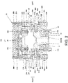
- Fig. 2 is a perspective view illustrating an outline configuration of the joint structure for the robot according to Embodiment 1. Note that, in Fig. 2 , an up-and-down direction and a left-and-right direction in the joint structure for the robot are expressed as an up-and-down direction and a left-and-right direction in the drawing.
- a joint structure 100 for the robot according to Embodiment 1 includes a first link 10, a second link 20, a first actuator 30A, a second actuator 30B, and a joint part 40.
- the first link 10 and the second link 20 are rotatably coupled to each other via the joint part 40.
- joint structure 100 for the robot according to Embodiment 1 is configured so that the first link 10 pivots relatively to the second link 20 by the first actuator 30A and the second actuator 30B carrying out rotating operation (rotary motion).
- the joint structure 100 for the robot according to Embodiment 1 may be configured such that the first link 10 constitutes a lower-half part of the body of the robot 200, the second link 20 constitutes an upper-half part of the body of the robot 200, and the joint part 40 constitutes a waist joint of the robot.
- the joint structure 100 may be configured such that, for example, the first link 10 constitutes a hand part of the robot 200, the second link 20 constitutes a forearm part of the robot 200, and the joint part 40 constitutes a wrist joint.
- the joint structure 100 may be configured so that, for example, the first link 10 constitutes an upper-leg part of the robot 200, the second link 20 constitutes a lower-leg part of the robot 200, and the joint part 40 constitutes an ankle joint.
- the joint structure 100 may be configured so that, for example, the first link 10 constitutes an upper-half part of the body of the robot 200, the second link 20 constitutes a head part of the robot 200, and the joint part 40 constitutes a neck joint.
- the first link 10 is formed in a box shape, and it is fixed to a lower part of a first rotary member 41 of the joint part 40 via suitable members (for example, fastening members, such as bolts and nuts).
- the first rotary member 41 is comprised of a bevel gear, and a first shank 11 of a shaft member 1 is fitted into an inner circumferential surface thereof via bearing members 2 and 3.
- Ball bearings may be used as the bearing members 2 and 3.
- the shaft member 1 is formed substantially in a T-shape, and has the first shank 11 and a pair of second shanks 12A and 12B.
- the first shank 11 is disposed so that its axial center is oriented in the first direction (here, the up-and-down direction), and a pair of second shanks 12A and 12B are disposed so that their axial centers are oriented in a second direction (here, the left-and-right direction) which is perpendicular to the first direction.
- the first link 10 can rotate around the first shank 11 relatively to the second link 20 when the first rotary member 41 rotates.
- the shaft member 1 may be formed in a cross shape.
- the second link 20 has a pair of plate-like first members 21A and 21B, and a casing 22.
- the first members 21A and 21B are disposed so that their principal surfaces oppose to each other.
- Through-holes 22A and 22B formed in a stepped shape are formed in the principal surfaces of the first members 21A and 21B, respectively.
- the casing 22 is disposed in a space between the first members 21A and 21B.
- the first actuator 30A and the second actuator 30B are disposed in the casing 22 so that they are lined up in the second direction.
- first actuator 30A and the second actuator 30B are each comprised of a servo motor.
- a first rotary transmitting member 51A is fitted into a shank 31A of the first actuator 30A.
- the first rotary transmitting member 51A is fixed to the shank 31A by fastening members (here, bolts) 32A.
- a first rotary transmitting member 51B is fitted onto a shank 31B of the second actuator 30B.
- the first rotary transmitting member 51B is fixed to the shank 31B by fastening members 32B (here, bolts) 32B.
- a second rotary transmitting member 52A meshes (engages) with the first rotary transmitting member 51A.
- the first rotary transmitting member 51A and the second rotary transmitting member 52A are each comprised of a bevel gear.
- the second rotary transmitting member 52A is disposed so that its axial center is oriented in the second direction, and a through-hole is formed therein. Note that the first rotary transmitting member 51A and the second rotary transmitting member 52A may be referred to as "the rotary transmitting member(s)."
- a second rotary member 42A is disposed in a left end part of the second rotary transmitting member 52A.
- the second rotary member 42A is comprised of a bevel gear, and it is disposed so that its axial center is in agreement with the axial center of the second rotary transmitting member 52A. Further, a through-hole is formed in the second rotary member 42A.
- the second shank 12A of the shaft member 1 is fitted into an inner circumferential surface of the second rotary member 42A via a bearing member 4A.
- a second rotary transmitting member 52B meshes (engages) with the first rotary transmitting member 51B.
- the first rotary transmitting member 51B and the second rotary transmitting member 52B are each comprised of a bevel gear.
- the second rotary transmitting member 52B is disposed so that its axial center is oriented in the second direction, and a through-hole is formed therein. Note that the first rotary transmitting member 51B and the second rotary transmitting member 52B may be referred to as "the rotary transmitting member(s)."
- a second rotary member 42B is disposed in a left end part of the second rotary transmitting member 52B.
- the second rotary member 42B is comprised of a bevel gear, and it is disposed so that its axial center is in agreement with the axial center of the second rotary transmitting member 52B. Further, a through-hole is formed in the second rotary member 42B.
- the second shank 12B of the shaft member 1 is fitted into an inner circumferential surface of the second rotary member 42B via a bearing member 4B.
- a base-end part (here, a right end part) of the second rotary transmitting member 52A is inserted into the through-hole 22A.
- a plate-like attaching member 60A is disposed at the through-hole 22A so that it covers the through-hole 22A.
- a protrusion 61A is provided to the attaching member 60A.
- the protrusion 61A is formed so that its tip-end face (here, a left end face) contacts the base-end part of the second rotary transmitting member 52A.
- a bearing member 5A is disposed so that it contacts the stepped part of the through-hole 22A, an outer circumferential surface of the protrusion 61A, and an outer circumferential surface of the base-end part of the second rotary transmitting member 52A.
- a ball bearing may be used as the bearing member 5A.
- the attaching member 60A is fastened to the first member 21A by a fastening member 70A. Therefore, the second rotary transmitting member 52A and the second rotary member 42A can be pressed to the left (inwardly).
- the fastening member 70A when seen in the second direction, is disposed so that it does not overlap with the second shank 12A. In more detail, the fastening member 70A is disposed so that it is located outside the through-hole 22A.
- a through-hole 62A extending in the thickness direction is formed in the protrusion 61A of the attaching member 60A so that it communicates with the through-holes of the second rotary member 42A and the second rotary transmitting member 52A.
- a pressing member 81A, a collar member 82A, and a bearing member 83A are disposed in the through-hole 62A.
- the pressing member 81A is comprised of a fastening member (bolt), and has a head and a shank.
- the pressing member 81A is disposed so that its axial center of the shank extends in the second direction. That is, when seen in the second direction, the pressing member 81A is disposed so that it overlaps with the second shank 12A. Further, a tip-end part of the shank of the pressing member 81A is connected to a tip-end part of the second shank 12A.
- the collar member 82A is formed in a cylindrical shape, and it is disposed so that its tip-end face contacts a tip-end face (a right end face) of the second shank 12A. Further, the shank of the pressing member 81A is inserted into an interior space of the collar member 82A.
- the bearing member 83A is disposed between a left end face of the head of the pressing member 81A and a base-end face (a right end face) of the collar member 82A.
- the bearing member 83A is comprised of a ball bearing with a flange, and this flange part is in contact with the base-end part of the second rotary transmitting member 52A.
- the second rotary member 42A can be pressed inwardly (brought closer to the second rotary member 42B) via the second rotary transmitting member 52A.
- the wobbles can be eliminated only by thrusting the pressing member 81A into the second shank 12A.
- the bearing member 83A is comprised of the ball bearing with the flange, and by the flange part contacting the second rotary transmitting member 52A, the pressing member 81A presses the second rotary transmitting member 52A and the second rotary member 42A, it is not limited to this configuration.
- a stepped part may be provided to the base-end part of the second rotary transmitting member 52A, and the bearing member 83A may be disposed at the stepped part. That is, without using the flange part, the pressing member 81A can press the second rotary transmitting member 52A and the second rotary member 42A.
- various ball bearings may be used as the bearing member 83A.
- a base-end part (here, a left end part) of the second rotary transmitting member 52B is inserted into the through-hole 22B.
- a plate-like attaching member 60B is disposed at through-hole 22B so that it covers the through-hole 22B.
- a protrusion 61B is provided to the attaching member 60B.
- the protrusion 61B is formed so that its tip-end face (here, a right end face) contacts the base-end part of the second rotary transmitting member 52B.
- a bearing member 5B is disposed so that it contacts the stepped part of the through-hole 22B, an outer circumferential surface of the protrusion 61B, and an outer circumferential surface of the base-end part of the second rotary transmitting member 52B.
- a ball bearing may be used as the bearing member 5B.
- the attaching member 60B is fastened to the first member 21B by a fastening member 70B. Therefore, the second rotary transmitting member 52B and the second rotary member 42B can be pressed to the right.
- the fastening member 70B when seen in the second direction, is disposed so that it does not overlap with the second shank 12B. In more detail, the fastening member 70B is disposed so that it is located outside the through-hole 22B.
- a through-hole 62B extending in the thickness direction is formed in the protrusion 61B of the attaching member 60B so that it communicates with the through-holes of the second rotary member 42B and the second rotary transmitting member 52B.
- a pressing member 81B, a collar member 82B, and a bearing member 83B are disposed at the through-hole 62B.
- the pressing member 81B is comprised of a fastening member (bolt), and has a head and a shank.
- the pressing member 81B is disposed so that its axial center of the shank extends in the second direction. That is, when seen in the second direction, the pressing member 81B is disposed so that it overlaps with the second shank 12B. Further, a tip-end part of the shank of the pressing member 81B is connected to a tip-end part of the second shank 12B.
- the collar member 82B is formed in a cylindrical shape, and it is disposed so that its tip-end face contacts a tip-end face (a left end face) of the second shank 12B. Further, a shank of the pressing member 81B is inserted into an interior space of the collar member 82B.
- the bearing member 83B is disposed between a right end face of the head of the pressing member 81B and a base-end face (a left end face) of the collar member 82B.
- the bearing member 83B is comprised of a ball bearing with a flange, and the flange part is in contact with the base-end part of the second rotary transmitting member 52B.
- the second rotary member 42B can be pressed inwardly (brought closer to the second rotary member 42A) via the second rotary transmitting member 52B.
- the wobbles can be eliminated only by thrusting the pressing member 81B into the second shank 12B.
- the bearing member 83B is comprised of the ball bearing with the flange, and by the flange part contacting the second rotary transmitting member 52B, the pressing member 81B presses the second rotary transmitting member 52B and the second rotary member 42B, it is not limited to this configuration.
- a stepped part may be provided in the base-end part of the second rotary transmitting member 52B, and the bearing member 83B may be disposed at the stepped part. That is, without using the flange part, the pressing member 81B can press the second rotary transmitting member 52B and the second rotary member 42B.
- various ball bearings may be used as the bearing member 83B.
- the second rotary member 42A can be pressed inwardly (brought closer to the second rotary member 42B) via the second rotary transmitting member 52A.
- the differential gear device can suppress the generation of the wobbles between the first rotary transmitting member 51A and the second rotary transmitting member 52A, and/or between the second rotary member 42A and the first rotary member 41. Further, even if the wobbles occur, the wobbles can be eliminated only by thrusting the pressing member 81A into the second shank 12A. That is, the rigidity of the joint part 40 can be increased.
- the second rotary member 42B can be pressed inwardly (brought closer to the second rotary member 42A) via the second rotary transmitting member 52B.
- the differential gear device can suppress the generation of the wobbles between the first rotary transmitting member 51B and the second rotary transmitting member 52B, and/or between the second rotary member 42B and the first rotary member 41. Further, even if the wobbles occur, the wobbles can be eliminated only by thrusting the pressing member 81B into the second shank 12B. That is, the rigidity of the joint part 40 can be increased.
- the bearing member 83A is comprised of the ball bearing with the flange, and the flange part contacts the second rotary transmitting member 52A.
- the pressing member 81A presses the second rotary transmitting member 52A and the second rotary member 42A via the flange part.
- the joint part 40 can be downsized.
- the bearing member 83B is comprised of the ball bearing with the flange, and the flange part contacts the second rotary transmitting member 52B.
- the pressing member 81B presses the second rotary transmitting member 52B and the second rotary member 42B via the flange part.
- the joint part 40 can be downsized.
- the attaching member 60A is fastened to the first member 21A by the fastening member 70A. Therefore, the second rotary transmitting member 52A and the second rotary member 42A can be pressed to the left, and the engagement between the first rotary transmitting member 51A and the second rotary transmitting member 52A, and/or the engagement between the second rotary member 42A and the first rotary member 41 can fully be secured. Moreover, since the fastening member 70A is disposed so that it does not overlap with the second shank 12A, the operating range of the joint part 40 can fully be secured.
- the attaching member 60B is fastened to the first member 21B by the fastening member 70B. Therefore, the second rotary transmitting member 52B and the second rotary member 42B can be pressed to the left, and the engagement between the first rotary transmitting member 51B and the second rotary transmitting member 52B, and/or the engagement between the second rotary member 42B and the first rotary member 41 can fully be secured. Moreover, since the fastening member 70B is disposed so that it does not overlap with the second shank 12B, the operating range of the joint part 40 can fully be secured.
- the amplitude of the first link 10 which carries out the pivot operation can be reduced corresponding to the rotating operation of the first actuator 30A and the second actuator 30B.
- the joint structure 100 can be reduced in cost, and, as a result, the robot can be reduced in cost. Further, the control of the first actuator 30A and the second actuator 30B by the control device 110 becomes easier.
- the bevel gear is used as the rotary transmitting member to transmit the rotational movement of the actuator to the second rotary member
- Various known mechanisms can be used as the rotary transmitting member, as long as it can transmit the rotational movement of the actuator to the second rotary member, and therefore, it may adopt any type.
- the rotational movement of the actuator may be converted into the forward and backward movement so as to transmit it to the second rotary member.
- a cylinder for example, a ball-screw mechanism which constitutes the linear actuator constitutes the rotary transmitting member.
- the joint structure for the robot of the present disclosure can eliminate the wobbles or can suppress the generation of the wobbles even if the wobbles occur, it is useful in the field of the industrial robots.
Landscapes
- Engineering & Computer Science (AREA)
- Mechanical Engineering (AREA)
- Robotics (AREA)
- Manipulator (AREA)
- General Engineering & Computer Science (AREA)
Abstract
Description
- The present disclosure relates to a joint structure for a robot.
- Manipulator devices used for a painting work are known, which are provided with a nozzle. The nozzle rotates with two degrees of freedom, and has a gear part which is sandwiched between two bevel gears and is disposed at a base body so as to mesh with the bevel gears (for example, see Patent Document 1).
- [Patent Document 1]
JP1995-024771A - However, according to the manipulator device disclosed in
Patent Document 1, it does not disclose how the two bevel gears and the gear part are attached to the base body. Moreover, since a thrust is applied to the bevel gears in the axial direction, the engagement between the bevel gears and the gear part becomes loose, and therefore, wobbles (rattling) may occur. - The present disclosure is made in view of solving the above-described conventional problems, and one purpose thereof is to provide a joint structure for a robot, which, in a differential gear device, by pressing a second rotary member against a second shank with a pressing member so that a pair of second rotary members may approach each other, can eliminate wobbles or can suppress generation of the wobbles, even if the wobbles occur.
- In order to solve the conventional problem, a joint structure for a robot according to the present disclosure includes a first link and a second link rotatably coupled to each other via a joint part, and a first actuator and a second actuator. The joint part has a first rotary member disposed so that an axial center thereof is oriented in a first direction and connected to the first link, a pair of second rotary members disposed so that an axial center thereof is oriented in a second direction perpendicular to the first direction, and so as to engage with the first rotary member, and a shaft member having a first shank and a pair of second shanks. The first actuator transmits a rotational movement thereof to one of the second rotary members via a rotary transmitting member. The second actuator transmits a rotational movement thereof to the other second rotary member via the rotary transmitting member. The shaft member is formed so that the first shank is oriented in the first direction and the pair of second shanks are oriented in the second direction. The first rotary member is disposed so that the first shank of the shaft member is inserted therein. The pair of second rotary members are disposed so that they oppose to each other and the second shank of the shaft member is inserted therein. The first link pivots relatively to the second link by the first actuator and the second actuator rotating. The joint structure further includes a pressing member connected to the second shank and configured to press the second rotary member inwardly.
- According to this, even if wobbles occur, the wobbles can be eliminated or generation of the wobbles can be suppressed.
- According to the joint structure for the robot of the present disclosure, even if wobbles occur, the wobbles can be eliminated or generation of the wobbles can be suppressed.
-
-
Fig. 1 is a schematic diagram illustrating an outline configuration of a robot provided with a joint structure according toEmbodiment 1. -
Fig. 2 is a cross-sectional view illustrating an outline configuration of the joint structure for the robot according toEmbodiment 1. - Hereinafter, one embodiment of the present disclosure will be described with reference to the drawings. Note that, throughout the drawings, the same reference characters are assigned to the same or corresponding parts to omit redundant description. Moreover, throughout the drawings, component are selectively illustrated for explaining the present disclosure, and illustration of other components may be omitted. The present disclosure is not limited to the following embodiment.
- A joint structure for a robot according to
Embodiment 1 includes a first link and a second link rotatably coupled to each other via a joint part, and a first actuator and a second actuator. The joint part has a first rotary member disposed so that an axial center thereof is oriented in a first direction and connected to the first link, a pair of second rotary members disposed so that an axial center thereof is oriented in a second direction perpendicular to the first direction, and so as to engage with the first rotary member, and a shaft member having a first shank and a pair of second shanks. The first actuator transmits a rotational movement thereof to one of the second rotary members via a rotary transmitting member. The second actuator transmits a rotational movement thereof to the other second rotary member via the rotary transmitting member. The shaft member is formed so that the first shank is oriented in the first direction and the pair of second shanks are oriented in the second direction. The first rotary member is disposed so that the first shank of the shaft member is inserted therein. The pair of second rotary members are disposed so that they oppose to each other and the second shank of the shaft member is inserted therein. The first link pivots relatively to the second link by the first actuator and the second actuator rotating. The joint structure further includes a pressing member connected to the second shank and configured to press the second rotary member inwardly. - Further, in the joint structure for the robot according to
Embodiment 1, the rotary transmitting member may have a first rotary transmitting member connected to the first actuator or the second actuator, and a second rotary transmitting member disposed so that an axial center thereof is oriented in the second direction and so as to engage with the first rotary transmitting member. - Further, in the joint structure for the robot according to
Embodiment 1, the pressing member may press the second rotary member via the second rotary transmitting member. - Further, in the joint structure for the robot according to
Embodiment 1, a bearing may be disposed between the pressing member and the second rotary transmitting member. - Further, in the joint structure for the robot according to
Embodiment 1, the pressing member may be disposed so as to overlap with the second shank, when seen in the second direction. - Moreover, the joint structure for the robot according to
Embodiment 1 may further include an attaching member disposed at the second link and configured to contact a base-end part of the second rotary transmitting member, and a fastening member configured to fasten the attaching member and the second link together. The fastening member may be disposed so as not to overlap with the second shank, when seen in the second direction. - Below, one example of the joint structure for the robot according to
Embodiment 1 is described with reference toFigs. 1 and2 . - First, a configuration of the robot provided with the joint structure according to
Embodiment 1 is described with reference toFig. 1 . -
Fig. 1 is a schematic diagram illustrating an outline configuration of the robot provided with the joint structure according toEmbodiment 1. - As illustrated in
Fig. 1 , arobot 200 includes abody 201, ahead 202, a pair ofarms 203, a pair oflegs 204, and a control device 110 disposed inside thebody 201. - The control device 110 includes a processor such as a microprocessor or a CPU, a memory such as a ROM and/or a RAM (not illustrated). The memory stores information on a basic program, various fixed data, etc. The processor controls various operations of the
robot 200 by reading and executing software, such as the basic program stored in the memory. - Note that the control device 110 may be comprised of a sole control device 110 which carries out a centralized control, or may be comprised of a plurality of control devices 110 which collaboratively carry out a distributed control. Further, the control device 110 may be comprised of the microcomputer, or may be comprised of a MPU, a PLC (Programmable Logic Controller), a logical circuit, etc.
-
Fig. 2 is a perspective view illustrating an outline configuration of the joint structure for the robot according toEmbodiment 1. Note that, inFig. 2 , an up-and-down direction and a left-and-right direction in the joint structure for the robot are expressed as an up-and-down direction and a left-and-right direction in the drawing. - As illustrated in
Fig. 2 , ajoint structure 100 for the robot according to Embodiment 1 includes afirst link 10, asecond link 20, afirst actuator 30A, asecond actuator 30B, and ajoint part 40. Thefirst link 10 and thesecond link 20 are rotatably coupled to each other via thejoint part 40. - Further, in the
joint structure 100 for the robot according toEmbodiment 1 is configured so that thefirst link 10 pivots relatively to thesecond link 20 by thefirst actuator 30A and thesecond actuator 30B carrying out rotating operation (rotary motion). - For example, the
joint structure 100 for the robot according to Embodiment 1 may be configured such that thefirst link 10 constitutes a lower-half part of the body of therobot 200, thesecond link 20 constitutes an upper-half part of the body of therobot 200, and thejoint part 40 constitutes a waist joint of the robot. Alternatively, thejoint structure 100 may be configured such that, for example, thefirst link 10 constitutes a hand part of therobot 200, thesecond link 20 constitutes a forearm part of therobot 200, and thejoint part 40 constitutes a wrist joint. - Alternatively, the
joint structure 100 may be configured so that, for example, thefirst link 10 constitutes an upper-leg part of therobot 200, thesecond link 20 constitutes a lower-leg part of therobot 200, and thejoint part 40 constitutes an ankle joint. Alternatively, thejoint structure 100 may be configured so that, for example, thefirst link 10 constitutes an upper-half part of the body of therobot 200, thesecond link 20 constitutes a head part of therobot 200, and thejoint part 40 constitutes a neck joint. - In
Embodiment 1, thefirst link 10 is formed in a box shape, and it is fixed to a lower part of afirst rotary member 41 of thejoint part 40 via suitable members (for example, fastening members, such as bolts and nuts). Thefirst rotary member 41 is comprised of a bevel gear, and afirst shank 11 of ashaft member 1 is fitted into an inner circumferential surface thereof via bearingmembers members - The
shaft member 1 is formed substantially in a T-shape, and has thefirst shank 11 and a pair ofsecond shanks first shank 11 is disposed so that its axial center is oriented in the first direction (here, the up-and-down direction), and a pair ofsecond shanks - Therefore, the
first link 10 can rotate around thefirst shank 11 relatively to thesecond link 20 when thefirst rotary member 41 rotates. Note that theshaft member 1 may be formed in a cross shape. - On the other hand, the
second link 20 has a pair of plate-likefirst members casing 22. Thefirst members holes first members - Further, the
casing 22 is disposed in a space between thefirst members first actuator 30A and thesecond actuator 30B are disposed in thecasing 22 so that they are lined up in the second direction. - Here, the
first actuator 30A and thesecond actuator 30B are each comprised of a servo motor. A firstrotary transmitting member 51A is fitted into ashank 31A of thefirst actuator 30A. The firstrotary transmitting member 51A is fixed to theshank 31A by fastening members (here, bolts) 32A. Similarly, a firstrotary transmitting member 51B is fitted onto ashank 31B of thesecond actuator 30B. The firstrotary transmitting member 51B is fixed to theshank 31B by fasteningmembers 32B (here, bolts) 32B. - A second
rotary transmitting member 52A meshes (engages) with the firstrotary transmitting member 51A. The firstrotary transmitting member 51A and the secondrotary transmitting member 52A are each comprised of a bevel gear. The secondrotary transmitting member 52A is disposed so that its axial center is oriented in the second direction, and a through-hole is formed therein. Note that the firstrotary transmitting member 51A and the secondrotary transmitting member 52A may be referred to as "the rotary transmitting member(s)." - A
second rotary member 42A is disposed in a left end part of the secondrotary transmitting member 52A. The secondrotary member 42A is comprised of a bevel gear, and it is disposed so that its axial center is in agreement with the axial center of the secondrotary transmitting member 52A. Further, a through-hole is formed in the secondrotary member 42A. Thesecond shank 12A of theshaft member 1 is fitted into an inner circumferential surface of the secondrotary member 42A via a bearingmember 4A. - Similarly, a second
rotary transmitting member 52B meshes (engages) with the firstrotary transmitting member 51B. The firstrotary transmitting member 51B and the secondrotary transmitting member 52B are each comprised of a bevel gear. The secondrotary transmitting member 52B is disposed so that its axial center is oriented in the second direction, and a through-hole is formed therein. Note that the firstrotary transmitting member 51B and the secondrotary transmitting member 52B may be referred to as "the rotary transmitting member(s)." - A
second rotary member 42B is disposed in a left end part of the secondrotary transmitting member 52B. The secondrotary member 42B is comprised of a bevel gear, and it is disposed so that its axial center is in agreement with the axial center of the secondrotary transmitting member 52B. Further, a through-hole is formed in the secondrotary member 42B. Thesecond shank 12B of theshaft member 1 is fitted into an inner circumferential surface of the secondrotary member 42B via a bearingmember 4B. - Moreover, a base-end part (here, a right end part) of the second
rotary transmitting member 52A is inserted into the through-hole 22A. A plate-like attachingmember 60A is disposed at the through-hole 22A so that it covers the through-hole 22A. - A
protrusion 61A is provided to the attachingmember 60A. Theprotrusion 61A is formed so that its tip-end face (here, a left end face) contacts the base-end part of the secondrotary transmitting member 52A. Further, at the through-hole 22A, a bearingmember 5A is disposed so that it contacts the stepped part of the through-hole 22A, an outer circumferential surface of theprotrusion 61A, and an outer circumferential surface of the base-end part of the secondrotary transmitting member 52A. A ball bearing may be used as the bearingmember 5A. - The attaching
member 60A is fastened to thefirst member 21A by afastening member 70A. Therefore, the secondrotary transmitting member 52A and the secondrotary member 42A can be pressed to the left (inwardly). - Note that, when seen in the second direction, the
fastening member 70A is disposed so that it does not overlap with thesecond shank 12A. In more detail, thefastening member 70A is disposed so that it is located outside the through-hole 22A. - A through-
hole 62A extending in the thickness direction is formed in theprotrusion 61A of the attachingmember 60A so that it communicates with the through-holes of the secondrotary member 42A and the secondrotary transmitting member 52A. Apressing member 81A, acollar member 82A, and a bearingmember 83A are disposed in the through-hole 62A. - Here, the pressing
member 81A is comprised of a fastening member (bolt), and has a head and a shank. Thepressing member 81A is disposed so that its axial center of the shank extends in the second direction. That is, when seen in the second direction, the pressingmember 81A is disposed so that it overlaps with thesecond shank 12A. Further, a tip-end part of the shank of thepressing member 81A is connected to a tip-end part of thesecond shank 12A. - The
collar member 82A is formed in a cylindrical shape, and it is disposed so that its tip-end face contacts a tip-end face (a right end face) of thesecond shank 12A. Further, the shank of thepressing member 81A is inserted into an interior space of thecollar member 82A. - The bearing
member 83A is disposed between a left end face of the head of thepressing member 81A and a base-end face (a right end face) of thecollar member 82A. Here, the bearingmember 83A is comprised of a ball bearing with a flange, and this flange part is in contact with the base-end part of the secondrotary transmitting member 52A. - Thus, by connecting (threadedly engaging) the
pressing member 81A to thesecond shank 12A, the secondrotary member 42A can be pressed inwardly (brought closer to the secondrotary member 42B) via the secondrotary transmitting member 52A. Thus, it can suppress the generation of wobbles (rattling) between the firstrotary transmitting member 51A and the secondrotary transmitting member 52A and/or between the secondrotary member 42A and thefirst rotary member 41. Further, even if wobbles occur, the wobbles can be eliminated only by thrusting thepressing member 81A into thesecond shank 12A. - Note that, in
Embodiment 1, although the bearingmember 83A is comprised of the ball bearing with the flange, and by the flange part contacting the secondrotary transmitting member 52A, the pressingmember 81A presses the secondrotary transmitting member 52A and the secondrotary member 42A, it is not limited to this configuration. - For example, a stepped part may be provided to the base-end part of the second
rotary transmitting member 52A, and the bearingmember 83A may be disposed at the stepped part. That is, without using the flange part, the pressingmember 81A can press the secondrotary transmitting member 52A and the secondrotary member 42A. In this case, various ball bearings may be used as the bearingmember 83A. - Similarly, a base-end part (here, a left end part) of the second
rotary transmitting member 52B is inserted into the through-hole 22B. A plate-like attachingmember 60B is disposed at through-hole 22B so that it covers the through-hole 22B. - A
protrusion 61B is provided to the attachingmember 60B. Theprotrusion 61B is formed so that its tip-end face (here, a right end face) contacts the base-end part of the secondrotary transmitting member 52B. Further, at the through-hole 22B, a bearingmember 5B is disposed so that it contacts the stepped part of the through-hole 22B, an outer circumferential surface of theprotrusion 61B, and an outer circumferential surface of the base-end part of the secondrotary transmitting member 52B. A ball bearing may be used as the bearingmember 5B. - The attaching
member 60B is fastened to thefirst member 21B by afastening member 70B. Therefore, the secondrotary transmitting member 52B and the secondrotary member 42B can be pressed to the right. - Note that, when seen in the second direction, the
fastening member 70B is disposed so that it does not overlap with thesecond shank 12B. In more detail, thefastening member 70B is disposed so that it is located outside the through-hole 22B. - A through-
hole 62B extending in the thickness direction is formed in theprotrusion 61B of the attachingmember 60B so that it communicates with the through-holes of the secondrotary member 42B and the secondrotary transmitting member 52B. Apressing member 81B, acollar member 82B, and a bearingmember 83B are disposed at the through-hole 62B. - Here, the pressing
member 81B is comprised of a fastening member (bolt), and has a head and a shank. The pressingmember 81B is disposed so that its axial center of the shank extends in the second direction. That is, when seen in the second direction, the pressingmember 81B is disposed so that it overlaps with thesecond shank 12B. Further, a tip-end part of the shank of thepressing member 81B is connected to a tip-end part of thesecond shank 12B. - The
collar member 82B is formed in a cylindrical shape, and it is disposed so that its tip-end face contacts a tip-end face (a left end face) of thesecond shank 12B. Further, a shank of thepressing member 81B is inserted into an interior space of thecollar member 82B. - The bearing
member 83B is disposed between a right end face of the head of thepressing member 81B and a base-end face (a left end face) of thecollar member 82B. Here, the bearingmember 83B is comprised of a ball bearing with a flange, and the flange part is in contact with the base-end part of the secondrotary transmitting member 52B. - Thus, by connecting (threadedly engaging) the
pressing member 81B to thesecond shank 12B, the secondrotary member 42B can be pressed inwardly (brought closer to the secondrotary member 42A) via the secondrotary transmitting member 52B. Thus, it can suppress the generation of wobbles (rattling) between the firstrotary transmitting member 51B and the secondrotary transmitting member 52B, and/or between the secondrotary member 42B and thefirst rotary member 41. Further, even if the wobbles occur, the wobbles can be eliminated only by thrusting thepressing member 81B into thesecond shank 12B. - Note that, in
Embodiment 1, although the bearingmember 83B is comprised of the ball bearing with the flange, and by the flange part contacting the secondrotary transmitting member 52B, the pressingmember 81B presses the secondrotary transmitting member 52B and the secondrotary member 42B, it is not limited to this configuration. - For example, a stepped part may be provided in the base-end part of the second
rotary transmitting member 52B, and the bearingmember 83B may be disposed at the stepped part. That is, without using the flange part, the pressingmember 81B can press the secondrotary transmitting member 52B and the secondrotary member 42B. In this case, various ball bearings may be used as the bearingmember 83B. - In the
joint structure 100 for the robot according toEmbodiment 1 configured as described above, by connecting thepressing member 81A to thesecond shank 12A, the secondrotary member 42A can be pressed inwardly (brought closer to the secondrotary member 42B) via the secondrotary transmitting member 52A. - Thus, in the differential gear device, it can suppress the generation of the wobbles between the first
rotary transmitting member 51A and the secondrotary transmitting member 52A, and/or between the secondrotary member 42A and thefirst rotary member 41. Further, even if the wobbles occur, the wobbles can be eliminated only by thrusting thepressing member 81A into thesecond shank 12A. That is, the rigidity of thejoint part 40 can be increased. - In the
joint structure 100 for the robot according toEmbodiment 1, by connecting thepressing member 81B to thesecond shank 12B, the secondrotary member 42B can be pressed inwardly (brought closer to the secondrotary member 42A) via the secondrotary transmitting member 52B. - Thus, in the differential gear device, it can suppress the generation of the wobbles between the first
rotary transmitting member 51B and the secondrotary transmitting member 52B, and/or between the secondrotary member 42B and thefirst rotary member 41. Further, even if the wobbles occur, the wobbles can be eliminated only by thrusting thepressing member 81B into thesecond shank 12B. That is, the rigidity of thejoint part 40 can be increased. - Moreover, in the
joint structure 100 for the robot according toEmbodiment 1, the bearingmember 83A is comprised of the ball bearing with the flange, and the flange part contacts the secondrotary transmitting member 52A. Thepressing member 81A presses the secondrotary transmitting member 52A and the secondrotary member 42A via the flange part. - Thus, since it is not necessary to provide the stepped part to the second
rotary transmitting member 52A, and it is not necessary to form the large through-hole 62A (increase the volume of the through-hole 62A), thejoint part 40 can be downsized. - Further, in the
joint structure 100 for the robot according toEmbodiment 1, the bearingmember 83B is comprised of the ball bearing with the flange, and the flange part contacts the secondrotary transmitting member 52B. The pressingmember 81B presses the secondrotary transmitting member 52B and the secondrotary member 42B via the flange part. - Thus, since it is not necessary to provide the stepped part to the second
rotary transmitting member 52B, and it is not necessary to form the large through-hole 62B (increase the volume of the through-hole 62B), thejoint part 40 can be downsized. - Further, in the
joint structure 100 for the robot according toEmbodiment 1, the attachingmember 60A is fastened to thefirst member 21A by thefastening member 70A. Therefore, the secondrotary transmitting member 52A and the secondrotary member 42A can be pressed to the left, and the engagement between the firstrotary transmitting member 51A and the secondrotary transmitting member 52A, and/or the engagement between the secondrotary member 42A and thefirst rotary member 41 can fully be secured. Moreover, since thefastening member 70A is disposed so that it does not overlap with thesecond shank 12A, the operating range of thejoint part 40 can fully be secured. - Further, in the
joint structure 100 for the robot according toEmbodiment 1, the attachingmember 60B is fastened to thefirst member 21B by thefastening member 70B. Therefore, the secondrotary transmitting member 52B and the secondrotary member 42B can be pressed to the left, and the engagement between the firstrotary transmitting member 51B and the secondrotary transmitting member 52B, and/or the engagement between the secondrotary member 42B and thefirst rotary member 41 can fully be secured. Moreover, since thefastening member 70B is disposed so that it does not overlap with thesecond shank 12B, the operating range of thejoint part 40 can fully be secured. - Further, in the
joint structure 100 for the robot according toEmbodiment 1, when thefirst rotary member 41 and thesecond rotary members first rotary member 41 is larger than the number of teeth of thesecond rotary members first link 10 with respect to thesecond link 20 can be increased. - Further, in the
joint structure 100 for the robot according toEmbodiment 1, when thefirst rotary member 41 and thesecond rotary members second rotary members first rotary member 41, the amplitude of thefirst link 10 which carries out the pivot operation can be reduced corresponding to the rotating operation of thefirst actuator 30A and thesecond actuator 30B. - Thus, it is not necessary to dispose an expensive highly-precise rotation sensor or current sensor, and therefore, the
joint structure 100 can be reduced in cost, and, as a result, the robot can be reduced in cost. Further, the control of thefirst actuator 30A and thesecond actuator 30B by the control device 110 becomes easier. - Note that although in the
joint structure 100 for the robot according toEmbodiment 1 the bevel gear is used as the rotary transmitting member to transmit the rotational movement of the actuator to the second rotary member, it is not limited to this configuration. Various known mechanisms can be used as the rotary transmitting member, as long as it can transmit the rotational movement of the actuator to the second rotary member, and therefore, it may adopt any type. For example, as disclosed inWO2018/097251A1 , using a linear actuator, the rotational movement of the actuator may be converted into the forward and backward movement so as to transmit it to the second rotary member. In this case, a cylinder (for example, a ball-screw mechanism) which constitutes the linear actuator constitutes the rotary transmitting member. - It is apparent for the person skilled in the art that many improvements or other embodiments of the present disclosure are possible from the above description. Therefore, the above description is to be interpreted only as illustration, and it is provided in order to teach the person skilled in the art the best mode that implements the present disclosure. The details of the structures and/or the functions may be changed substantially without departing from the present disclosure.
- Since the joint structure for the robot of the present disclosure can eliminate the wobbles or can suppress the generation of the wobbles even if the wobbles occur, it is useful in the field of the industrial robots.
-
- 1
- Shaft Member
- 2
- Bearing Member
- 4A
- Bearing Member
- 4B
- Bearing Member
- 5A
- Bearing Member
- 5B
- Bearing Member
- 10
- First Link
- 11
- First Shank
- 12A
- Second Shank
- 12B
- Second Shank
- 20
- Second Link
- 21A
- First Member
- 21B
- First Member
- 22
- Casing
- 22A
- Through-hole
- 22B
- Through-hole
- 30A
- First Actuator
- 30B
- Second Actuator
- 31A
- Shank
- 31B
- Shank
- 32A
- Fastening Member
- 32B
- Fastening Member
- 40
- Joint Part
- 41
- First Rotary Member
- 42A
- Second Rotary Member
- 42B
- Second Rotary Member
- 51A
- First Rotary Transmitting Member
- 51B
- First Rotary Transmitting Member
- 52A
- Second Rotary Transmitting Member
- 52B
- Second Rotary Transmitting Member
- 60A
- Attaching Member
- 60B
- Attaching Member
- 61A
- Protrusion
- 61B
- Protrusion
- 62A
- Through-hole
- 62B
- Through-hole
- 70A
- Fastening Member
- 70B
- Fastening Member
- 81A
- Pressing Member
- 81B
- Pressing Member
- 82A
- Collar Member
- 82B
- Collar Member
- 83A
- Bearing Member
- 83B
- Bearing Member
- 100
- Joint Structure
- 110
- Control Device
- 200
- Robot
- 201
- Body
- 202
- Head
- 203
- Arm
- 204
- Leg
Claims (6)
- A joint structure for a robot, comprising:a first link and a second link rotatably coupled to each other via a joint part; anda first actuator and a second actuator,wherein the joint part has a first rotary member disposed so that an axial center thereof is oriented in a first direction and connected to the first link, a pair of second rotary members disposed so that an axial center thereof is oriented in a second direction perpendicular to the first direction, and so as to engage with the first rotary member, and a shaft member having a first shank and a pair of second shanks,wherein the first actuator transmits a rotational movement thereof to one of the second rotary members via a rotary transmitting member,wherein the second actuator transmits a rotational movement thereof to the other second rotary member via the rotary transmitting member,wherein the shaft member is formed so that the first shank is oriented in the first direction and the pair of second shanks are oriented in the second direction,wherein the first rotary member is disposed so that the first shank of the shaft member is inserted therein,wherein the pair of second rotary members are disposed so that they oppose to each other and the second shank of the shaft member is inserted therein,wherein the first link pivots relatively to the second link by the first actuator and the second actuator rotating, andwherein the joint structure further comprises a pressing member connected to the second shank and configured to press the second rotary member inwardly.
- The joint structure of claim 1, wherein the rotary transmitting member has a first rotary transmitting member connected to the first actuator or the second actuator, and a second rotary transmitting member disposed so that an axial center thereof is oriented in the second direction and so as to engage with the first rotary transmitting member.
- The joint structure of claim 2, wherein the pressing member presses the second rotary member via the second rotary transmitting member.
- The joint structure of claim 3, wherein a bearing is disposed between the pressing member and the second rotary transmitting member.
- The joint structure of any one of claims 1 to 4, wherein the pressing member is disposed so as to overlap with the second shank, when seen in the second direction.
- The joint structure of any one of claims 1 to 5, further comprising:an attaching member disposed at the second link and configured to contact a base-end part of the second rotary transmitting member; anda fastening member configured to fasten the attaching member and the second link together,wherein the fastening member is disposed so as not to overlap with the second shank, when seen in the second direction.
Applications Claiming Priority (2)
| Application Number | Priority Date | Filing Date | Title |
|---|---|---|---|
| JP2019159742A JP7339817B2 (en) | 2019-09-02 | 2019-09-02 | robot joint structure |
| PCT/JP2020/033139 WO2021045063A1 (en) | 2019-09-02 | 2020-09-01 | Robot joint structure |
Publications (3)
| Publication Number | Publication Date |
|---|---|
| EP4026670A1 true EP4026670A1 (en) | 2022-07-13 |
| EP4026670A4 EP4026670A4 (en) | 2023-09-13 |
| EP4026670B1 EP4026670B1 (en) | 2025-11-19 |
Family
ID=74847920
Family Applications (1)
| Application Number | Title | Priority Date | Filing Date |
|---|---|---|---|
| EP20860908.1A Active EP4026670B1 (en) | 2019-09-02 | 2020-09-01 | Robot joint structure |
Country Status (6)
| Country | Link |
|---|---|
| US (1) | US11850737B2 (en) |
| EP (1) | EP4026670B1 (en) |
| JP (1) | JP7339817B2 (en) |
| KR (1) | KR102679106B1 (en) |
| CN (1) | CN113939387B (en) |
| WO (1) | WO2021045063A1 (en) |
Families Citing this family (2)
| Publication number | Priority date | Publication date | Assignee | Title |
|---|---|---|---|---|
| WO2022190719A1 (en) | 2021-03-09 | 2022-09-15 | 株式会社Soken | Target recognition device |
| CN113217528A (en) * | 2021-05-24 | 2021-08-06 | 东莞市原创玩具有限公司 | Model joint structure |
Family Cites Families (13)
| Publication number | Priority date | Publication date | Assignee | Title |
|---|---|---|---|---|
| US2680972A (en) * | 1953-01-08 | 1954-06-15 | Belock Instr Corp | Bevel gear differential assembly |
| SU598749A1 (en) * | 1975-11-20 | 1978-03-25 | Предприятие П/Я Р-6930 | Manipulator wrist assembly |
| GB8505746D0 (en) * | 1985-03-06 | 1985-04-11 | Universal Machine Intelligence | Robotic wrist & gripper |
| JPH06197492A (en) * | 1992-12-24 | 1994-07-15 | Sankyo Seiki Mfg Co Ltd | Compound drive |
| JPH0724774A (en) * | 1993-07-08 | 1995-01-27 | Bridgestone Corp | robot |
| JPH0724771A (en) | 1993-07-08 | 1995-01-27 | Bridgestone Corp | Manipulator device |
| CN102259337B (en) | 2010-05-28 | 2013-11-06 | 鸿富锦精密工业(深圳)有限公司 | Robot arm component |
| US8747486B2 (en) * | 2010-09-24 | 2014-06-10 | Gifu University | Humanoid electric hand |
| KR101483081B1 (en) * | 2014-01-16 | 2015-01-21 | 주식회사 로보스타 | Parallel robot wrist using differential gear |
| CN104942822B (en) | 2015-06-05 | 2017-03-08 | 上海宇航系统工程研究所 | A kind of two-freedom degree joint of robot for space |
| JP6644531B2 (en) | 2015-12-01 | 2020-02-12 | 株式会社アイエイアイ | Wrist unit and robot |
| JP2017226028A (en) | 2016-06-20 | 2017-12-28 | 株式会社アイエイアイ | Wrist unit and robot |
| US11511446B2 (en) | 2016-11-24 | 2022-11-29 | Kawasaki Jukogyo Kabushiki Kaisha | Joint structure for robot |
-
2019
- 2019-09-02 JP JP2019159742A patent/JP7339817B2/en active Active
-
2020
- 2020-09-01 KR KR1020227009142A patent/KR102679106B1/en active Active
- 2020-09-01 US US17/638,986 patent/US11850737B2/en active Active
- 2020-09-01 EP EP20860908.1A patent/EP4026670B1/en active Active
- 2020-09-01 WO PCT/JP2020/033139 patent/WO2021045063A1/en not_active Ceased
- 2020-09-01 CN CN202080042287.8A patent/CN113939387B/en active Active
Also Published As
| Publication number | Publication date |
|---|---|
| CN113939387B (en) | 2024-06-28 |
| EP4026670A4 (en) | 2023-09-13 |
| US20220266459A1 (en) | 2022-08-25 |
| JP7339817B2 (en) | 2023-09-06 |
| KR20220047852A (en) | 2022-04-19 |
| KR102679106B1 (en) | 2024-06-28 |
| JP2021037570A (en) | 2021-03-11 |
| EP4026670B1 (en) | 2025-11-19 |
| WO2021045063A1 (en) | 2021-03-11 |
| US11850737B2 (en) | 2023-12-26 |
| CN113939387A (en) | 2022-01-14 |
Similar Documents
| Publication | Publication Date | Title |
|---|---|---|
| KR101457147B1 (en) | Humanoid robot and shoulder joint assembly thereof | |
| CN100503181C (en) | Parallel Link Mechanism and Industrial Robot | |
| US9073216B2 (en) | Joint mechanism and robot having the same | |
| CN204748646U (en) | Robot joint reduction gear | |
| US11850737B2 (en) | Joint structure for robot | |
| JP2003025269A (en) | Offset rotary joint unit with rotation correction mechanism | |
| WO2013014720A1 (en) | Parallel link robot | |
| WO2016021099A1 (en) | Parallel link robot and parallel link structure | |
| JP2000343477A (en) | Robot joint structure | |
| EP0200202A2 (en) | Wrist mechanism for industrial robot | |
| CN209289324U (en) | A kind of sixdegree-of-freedom simulation and service robot suitable for service robot | |
| CN121447669A (en) | Dexterous thumb and manipulator | |
| KR102309012B1 (en) | Assist device | |
| JP6632430B2 (en) | Robot deceleration transmission | |
| US20210396304A1 (en) | Gear device | |
| EP4302940A1 (en) | Coupling device and robot | |
| JP7631771B2 (en) | Gearing and robots | |
| EP3546142B1 (en) | Joint structure for robot | |
| KR101201727B1 (en) | humanoid robot | |
| JP2024090459A (en) | Motor unit | |
| JP7828196B2 (en) | Robot arm, end effector, robot arm drive method, robot arm drive program | |
| EP4714612A1 (en) | Robot and joint apparatus for robot | |
| KR101201726B1 (en) | humanoid robot | |
| JP2015161382A (en) | Gear mechanism, transmission, and articulated robot arm | |
| JPS6186159A (en) | Hand-neck device of industrial robot |
Legal Events
| Date | Code | Title | Description |
|---|---|---|---|
| STAA | Information on the status of an ep patent application or granted ep patent |
Free format text: STATUS: THE INTERNATIONAL PUBLICATION HAS BEEN MADE |
|
| PUAI | Public reference made under article 153(3) epc to a published international application that has entered the european phase |
Free format text: ORIGINAL CODE: 0009012 |
|
| STAA | Information on the status of an ep patent application or granted ep patent |
Free format text: STATUS: REQUEST FOR EXAMINATION WAS MADE |
|
| 17P | Request for examination filed |
Effective date: 20220209 |
|
| AK | Designated contracting states |
Kind code of ref document: A1 Designated state(s): AL AT BE BG CH CY CZ DE DK EE ES FI FR GB GR HR HU IE IS IT LI LT LU LV MC MK MT NL NO PL PT RO RS SE SI SK SM TR |
|
| DAV | Request for validation of the european patent (deleted) | ||
| DAX | Request for extension of the european patent (deleted) | ||
| A4 | Supplementary search report drawn up and despatched |
Effective date: 20230810 |
|
| RIC1 | Information provided on ipc code assigned before grant |
Ipc: B25J 17/02 20060101ALI20230804BHEP Ipc: B25J 17/00 20060101ALI20230804BHEP Ipc: B25J 9/10 20060101ALI20230804BHEP Ipc: F16C 11/04 20060101ALI20230804BHEP Ipc: B25J 19/00 20060101AFI20230804BHEP |
|
| GRAP | Despatch of communication of intention to grant a patent |
Free format text: ORIGINAL CODE: EPIDOSNIGR1 |
|
| STAA | Information on the status of an ep patent application or granted ep patent |
Free format text: STATUS: GRANT OF PATENT IS INTENDED |
|
| RIC1 | Information provided on ipc code assigned before grant |
Ipc: B25J 19/00 20060101AFI20250611BHEP Ipc: F16C 11/04 20060101ALI20250611BHEP Ipc: B25J 9/10 20060101ALI20250611BHEP Ipc: B25J 17/00 20060101ALI20250611BHEP Ipc: B25J 17/02 20060101ALI20250611BHEP |
|
| INTG | Intention to grant announced |
Effective date: 20250627 |
|
| GRAS | Grant fee paid |
Free format text: ORIGINAL CODE: EPIDOSNIGR3 |
|
| GRAA | (expected) grant |
Free format text: ORIGINAL CODE: 0009210 |
|
| STAA | Information on the status of an ep patent application or granted ep patent |
Free format text: STATUS: THE PATENT HAS BEEN GRANTED |
|
| AK | Designated contracting states |
Kind code of ref document: B1 Designated state(s): AL AT BE BG CH CY CZ DE DK EE ES FI FR GB GR HR HU IE IS IT LI LT LU LV MC MK MT NL NO PL PT RO RS SE SI SK SM TR |
|
| REG | Reference to a national code |
Ref country code: CH Ref legal event code: F10 Free format text: ST27 STATUS EVENT CODE: U-0-0-F10-F00 (AS PROVIDED BY THE NATIONAL OFFICE) Effective date: 20251119 Ref country code: GB Ref legal event code: FG4D |
|
| REG | Reference to a national code |
Ref country code: DE Ref legal event code: R096 Ref document number: 602020062548 Country of ref document: DE |
|
| REG | Reference to a national code |
Ref country code: IE Ref legal event code: FG4D |
|
| REG | Reference to a national code |
Ref country code: NL Ref legal event code: MP Effective date: 20251119 |
|
| PG25 | Lapsed in a contracting state [announced via postgrant information from national office to epo] |
Ref country code: ES Free format text: LAPSE BECAUSE OF FAILURE TO SUBMIT A TRANSLATION OF THE DESCRIPTION OR TO PAY THE FEE WITHIN THE PRESCRIBED TIME-LIMIT Effective date: 20251119 |
|
| REG | Reference to a national code |
Ref country code: LT Ref legal event code: MG9D |
|
| PG25 | Lapsed in a contracting state [announced via postgrant information from national office to epo] |
Ref country code: NO Free format text: LAPSE BECAUSE OF FAILURE TO SUBMIT A TRANSLATION OF THE DESCRIPTION OR TO PAY THE FEE WITHIN THE PRESCRIBED TIME-LIMIT Effective date: 20260219 |
|
| PG25 | Lapsed in a contracting state [announced via postgrant information from national office to epo] |
Ref country code: HR Free format text: LAPSE BECAUSE OF FAILURE TO SUBMIT A TRANSLATION OF THE DESCRIPTION OR TO PAY THE FEE WITHIN THE PRESCRIBED TIME-LIMIT Effective date: 20251119 Ref country code: FI Free format text: LAPSE BECAUSE OF FAILURE TO SUBMIT A TRANSLATION OF THE DESCRIPTION OR TO PAY THE FEE WITHIN THE PRESCRIBED TIME-LIMIT Effective date: 20251119 Ref country code: AT Free format text: LAPSE BECAUSE OF FAILURE TO SUBMIT A TRANSLATION OF THE DESCRIPTION OR TO PAY THE FEE WITHIN THE PRESCRIBED TIME-LIMIT Effective date: 20251119 |
|
| REG | Reference to a national code |
Ref country code: AT Ref legal event code: MK05 Ref document number: 1858467 Country of ref document: AT Kind code of ref document: T Effective date: 20251119 |
|
| PG25 | Lapsed in a contracting state [announced via postgrant information from national office to epo] |
Ref country code: NL Free format text: LAPSE BECAUSE OF FAILURE TO SUBMIT A TRANSLATION OF THE DESCRIPTION OR TO PAY THE FEE WITHIN THE PRESCRIBED TIME-LIMIT Effective date: 20251119 |
|
| PG25 | Lapsed in a contracting state [announced via postgrant information from national office to epo] |
Ref country code: RS Free format text: LAPSE BECAUSE OF FAILURE TO SUBMIT A TRANSLATION OF THE DESCRIPTION OR TO PAY THE FEE WITHIN THE PRESCRIBED TIME-LIMIT Effective date: 20260219 |
|
| PG25 | Lapsed in a contracting state [announced via postgrant information from national office to epo] |
Ref country code: IS Free format text: LAPSE BECAUSE OF FAILURE TO SUBMIT A TRANSLATION OF THE DESCRIPTION OR TO PAY THE FEE WITHIN THE PRESCRIBED TIME-LIMIT Effective date: 20260319 |
|
| PG25 | Lapsed in a contracting state [announced via postgrant information from national office to epo] |
Ref country code: PT Free format text: LAPSE BECAUSE OF FAILURE TO SUBMIT A TRANSLATION OF THE DESCRIPTION OR TO PAY THE FEE WITHIN THE PRESCRIBED TIME-LIMIT Effective date: 20260319 |
|
| PG25 | Lapsed in a contracting state [announced via postgrant information from national office to epo] |
Ref country code: PL Free format text: LAPSE BECAUSE OF FAILURE TO SUBMIT A TRANSLATION OF THE DESCRIPTION OR TO PAY THE FEE WITHIN THE PRESCRIBED TIME-LIMIT Effective date: 20251119 |
|
| PG25 | Lapsed in a contracting state [announced via postgrant information from national office to epo] |
Ref country code: LV Free format text: LAPSE BECAUSE OF FAILURE TO SUBMIT A TRANSLATION OF THE DESCRIPTION OR TO PAY THE FEE WITHIN THE PRESCRIBED TIME-LIMIT Effective date: 20251119 |
|
| PG25 | Lapsed in a contracting state [announced via postgrant information from national office to epo] |
Ref country code: BG Free format text: LAPSE BECAUSE OF FAILURE TO SUBMIT A TRANSLATION OF THE DESCRIPTION OR TO PAY THE FEE WITHIN THE PRESCRIBED TIME-LIMIT Effective date: 20251119 |
|
| PG25 | Lapsed in a contracting state [announced via postgrant information from national office to epo] |
Ref country code: LT Free format text: LAPSE BECAUSE OF FAILURE TO SUBMIT A TRANSLATION OF THE DESCRIPTION OR TO PAY THE FEE WITHIN THE PRESCRIBED TIME-LIMIT Effective date: 20251119 |
|
| PG25 | Lapsed in a contracting state [announced via postgrant information from national office to epo] |
Ref country code: SM Free format text: LAPSE BECAUSE OF FAILURE TO SUBMIT A TRANSLATION OF THE DESCRIPTION OR TO PAY THE FEE WITHIN THE PRESCRIBED TIME-LIMIT Effective date: 20251119 |
|
| PG25 | Lapsed in a contracting state [announced via postgrant information from national office to epo] |
Ref country code: DK Free format text: LAPSE BECAUSE OF FAILURE TO SUBMIT A TRANSLATION OF THE DESCRIPTION OR TO PAY THE FEE WITHIN THE PRESCRIBED TIME-LIMIT Effective date: 20251119 |
|
| PG25 | Lapsed in a contracting state [announced via postgrant information from national office to epo] |
Ref country code: IT Free format text: LAPSE BECAUSE OF FAILURE TO SUBMIT A TRANSLATION OF THE DESCRIPTION OR TO PAY THE FEE WITHIN THE PRESCRIBED TIME-LIMIT Effective date: 20251119 |
|
| PG25 | Lapsed in a contracting state [announced via postgrant information from national office to epo] |
Ref country code: EE Free format text: LAPSE BECAUSE OF FAILURE TO SUBMIT A TRANSLATION OF THE DESCRIPTION OR TO PAY THE FEE WITHIN THE PRESCRIBED TIME-LIMIT Effective date: 20251119 |
|
| PG25 | Lapsed in a contracting state [announced via postgrant information from national office to epo] |
Ref country code: CZ Free format text: LAPSE BECAUSE OF FAILURE TO SUBMIT A TRANSLATION OF THE DESCRIPTION OR TO PAY THE FEE WITHIN THE PRESCRIBED TIME-LIMIT Effective date: 20251119 |
|
| PG25 | Lapsed in a contracting state [announced via postgrant information from national office to epo] |
Ref country code: SK Free format text: LAPSE BECAUSE OF FAILURE TO SUBMIT A TRANSLATION OF THE DESCRIPTION OR TO PAY THE FEE WITHIN THE PRESCRIBED TIME-LIMIT Effective date: 20251119 |
|
| PG25 | Lapsed in a contracting state [announced via postgrant information from national office to epo] |
Ref country code: SE Free format text: LAPSE BECAUSE OF FAILURE TO SUBMIT A TRANSLATION OF THE DESCRIPTION OR TO PAY THE FEE WITHIN THE PRESCRIBED TIME-LIMIT Effective date: 20251119 |