EP4026669A1 - Spherical joint and robot joint structure comprising same - Google Patents
Spherical joint and robot joint structure comprising same Download PDFInfo
- Publication number
- EP4026669A1 EP4026669A1 EP20860169.0A EP20860169A EP4026669A1 EP 4026669 A1 EP4026669 A1 EP 4026669A1 EP 20860169 A EP20860169 A EP 20860169A EP 4026669 A1 EP4026669 A1 EP 4026669A1
- Authority
- EP
- European Patent Office
- Prior art keywords
- joint
- robot
- spherical joint
- circumferential surface
- inner circumferential
- Prior art date
- Legal status (The legal status is an assumption and is not a legal conclusion. Google has not performed a legal analysis and makes no representation as to the accuracy of the status listed.)
- Withdrawn
Links
Images


Classifications
-
- B—PERFORMING OPERATIONS; TRANSPORTING
- B25—HAND TOOLS; PORTABLE POWER-DRIVEN TOOLS; MANIPULATORS
- B25J—MANIPULATORS; CHAMBERS PROVIDED WITH MANIPULATION DEVICES
- B25J17/00—Joints
-
- B—PERFORMING OPERATIONS; TRANSPORTING
- B25—HAND TOOLS; PORTABLE POWER-DRIVEN TOOLS; MANIPULATORS
- B25J—MANIPULATORS; CHAMBERS PROVIDED WITH MANIPULATION DEVICES
- B25J17/00—Joints
- B25J17/02—Wrist joints
- B25J17/0283—Three-dimensional joints
-
- B—PERFORMING OPERATIONS; TRANSPORTING
- B25—HAND TOOLS; PORTABLE POWER-DRIVEN TOOLS; MANIPULATORS
- B25J—MANIPULATORS; CHAMBERS PROVIDED WITH MANIPULATION DEVICES
- B25J9/00—Program-controlled manipulators
- B25J9/0006—Exoskeletons, i.e. resembling a human figure
-
- B—PERFORMING OPERATIONS; TRANSPORTING
- B25—HAND TOOLS; PORTABLE POWER-DRIVEN TOOLS; MANIPULATORS
- B25J—MANIPULATORS; CHAMBERS PROVIDED WITH MANIPULATION DEVICES
- B25J9/00—Program-controlled manipulators
- B25J9/10—Program-controlled manipulators characterised by positioning means for manipulator elements
-
- F—MECHANICAL ENGINEERING; LIGHTING; HEATING; WEAPONS; BLASTING
- F16—ENGINEERING ELEMENTS AND UNITS; GENERAL MEASURES FOR PRODUCING AND MAINTAINING EFFECTIVE FUNCTIONING OF MACHINES OR INSTALLATIONS; THERMAL INSULATION IN GENERAL
- F16C—SHAFTS; FLEXIBLE SHAFTS; ELEMENTS OR CRANKSHAFT MECHANISMS; ROTARY BODIES OTHER THAN GEARING ELEMENTS; BEARINGS
- F16C11/00—Pivots; Pivotal connections
- F16C11/04—Pivotal connections
- F16C11/06—Ball-joints; Other joints having more than one degree of angular freedom, i.e. universal joints
-
- F—MECHANICAL ENGINEERING; LIGHTING; HEATING; WEAPONS; BLASTING
- F16—ENGINEERING ELEMENTS AND UNITS; GENERAL MEASURES FOR PRODUCING AND MAINTAINING EFFECTIVE FUNCTIONING OF MACHINES OR INSTALLATIONS; THERMAL INSULATION IN GENERAL
- F16C—SHAFTS; FLEXIBLE SHAFTS; ELEMENTS OR CRANKSHAFT MECHANISMS; ROTARY BODIES OTHER THAN GEARING ELEMENTS; BEARINGS
- F16C11/00—Pivots; Pivotal connections
- F16C11/04—Pivotal connections
- F16C11/06—Ball-joints; Other joints having more than one degree of angular freedom, i.e. universal joints
- F16C11/0614—Ball-joints; Other joints having more than one degree of angular freedom, i.e. universal joints the female part of the joint being open on two sides
-
- F—MECHANICAL ENGINEERING; LIGHTING; HEATING; WEAPONS; BLASTING
- F16—ENGINEERING ELEMENTS AND UNITS; GENERAL MEASURES FOR PRODUCING AND MAINTAINING EFFECTIVE FUNCTIONING OF MACHINES OR INSTALLATIONS; THERMAL INSULATION IN GENERAL
- F16C—SHAFTS; FLEXIBLE SHAFTS; ELEMENTS OR CRANKSHAFT MECHANISMS; ROTARY BODIES OTHER THAN GEARING ELEMENTS; BEARINGS
- F16C11/00—Pivots; Pivotal connections
- F16C11/04—Pivotal connections
- F16C11/06—Ball-joints; Other joints having more than one degree of angular freedom, i.e. universal joints
- F16C11/0619—Ball-joints; Other joints having more than one degree of angular freedom, i.e. universal joints the female part comprising a blind socket receiving the male part
- F16C11/0623—Construction or details of the socket member
- F16C11/0647—Special features relating to adjustment for wear or play; Wear indicators
-
- F—MECHANICAL ENGINEERING; LIGHTING; HEATING; WEAPONS; BLASTING
- F16—ENGINEERING ELEMENTS AND UNITS; GENERAL MEASURES FOR PRODUCING AND MAINTAINING EFFECTIVE FUNCTIONING OF MACHINES OR INSTALLATIONS; THERMAL INSULATION IN GENERAL
- F16C—SHAFTS; FLEXIBLE SHAFTS; ELEMENTS OR CRANKSHAFT MECHANISMS; ROTARY BODIES OTHER THAN GEARING ELEMENTS; BEARINGS
- F16C11/00—Pivots; Pivotal connections
- F16C11/04—Pivotal connections
- F16C11/10—Arrangements for locking
-
- F—MECHANICAL ENGINEERING; LIGHTING; HEATING; WEAPONS; BLASTING
- F16—ENGINEERING ELEMENTS AND UNITS; GENERAL MEASURES FOR PRODUCING AND MAINTAINING EFFECTIVE FUNCTIONING OF MACHINES OR INSTALLATIONS; THERMAL INSULATION IN GENERAL
- F16C—SHAFTS; FLEXIBLE SHAFTS; ELEMENTS OR CRANKSHAFT MECHANISMS; ROTARY BODIES OTHER THAN GEARING ELEMENTS; BEARINGS
- F16C11/00—Pivots; Pivotal connections
- F16C11/04—Pivotal connections
- F16C11/10—Arrangements for locking
- F16C11/103—Arrangements for locking frictionally clamped
- F16C11/106—Arrangements for locking frictionally clamped for ball joints
-
- F—MECHANICAL ENGINEERING; LIGHTING; HEATING; WEAPONS; BLASTING
- F16—ENGINEERING ELEMENTS AND UNITS; GENERAL MEASURES FOR PRODUCING AND MAINTAINING EFFECTIVE FUNCTIONING OF MACHINES OR INSTALLATIONS; THERMAL INSULATION IN GENERAL
- F16C—SHAFTS; FLEXIBLE SHAFTS; ELEMENTS OR CRANKSHAFT MECHANISMS; ROTARY BODIES OTHER THAN GEARING ELEMENTS; BEARINGS
- F16C9/00—Bearings for crankshafts or connecting-rods; Attachment of connecting-rods
- F16C9/04—Connecting-rod bearings; Attachments thereof
- F16C9/06—Arrangements for adjusting play in bearings, operating either automatically or not
-
- F—MECHANICAL ENGINEERING; LIGHTING; HEATING; WEAPONS; BLASTING
- F16—ENGINEERING ELEMENTS AND UNITS; GENERAL MEASURES FOR PRODUCING AND MAINTAINING EFFECTIVE FUNCTIONING OF MACHINES OR INSTALLATIONS; THERMAL INSULATION IN GENERAL
- F16C—SHAFTS; FLEXIBLE SHAFTS; ELEMENTS OR CRANKSHAFT MECHANISMS; ROTARY BODIES OTHER THAN GEARING ELEMENTS; BEARINGS
- F16C2226/00—Joining parts; Fastening; Assembling or mounting parts
- F16C2226/50—Positive connections
- F16C2226/60—Positive connections with threaded parts, e.g. bolt and nut connections
-
- F—MECHANICAL ENGINEERING; LIGHTING; HEATING; WEAPONS; BLASTING
- F16—ENGINEERING ELEMENTS AND UNITS; GENERAL MEASURES FOR PRODUCING AND MAINTAINING EFFECTIVE FUNCTIONING OF MACHINES OR INSTALLATIONS; THERMAL INSULATION IN GENERAL
- F16C—SHAFTS; FLEXIBLE SHAFTS; ELEMENTS OR CRANKSHAFT MECHANISMS; ROTARY BODIES OTHER THAN GEARING ELEMENTS; BEARINGS
- F16C2322/00—Apparatus used in shaping articles
- F16C2322/50—Hand tools, workshop equipment or manipulators
- F16C2322/59—Manipulators, e.g. robot arms
Definitions
- the present disclosure relates to a spherical joint and a joint structure for a robot having the same.
- a drive mechanism disclosed in Patent Document 1 is, for example, to drive a joint part, such as an ankle joint of a humanoid robot.
- a tip-end part of a first link member and a base-end part of a second link member, which constitute the ankle joint are coupled through a spherical joint.
- Patent Document 1 WO2017/094922A1
- the load of the robot may be applied to the spherical joint to cause rattling.
- the rattling may be caused in the spherical joint.
- the present disclosure is to solve the above-described conventional problem, and one purpose thereof is to provide a spherical joint, and a joint structure for a robot, having the spherical joint, capable of reducing a radius of curvature of an inner circumferential surface of a socket when rattling occurs to increase a contacting area with a ball member so as to eliminate the rattling or suppressing the rattling.
- a spherical joint in order to solve the conventional problem, includes a ball member, and a socket having an inner circumferential surface configured to spherically contact the ball member.
- the socket includes a cage part forming the inner circumferential surface and having an opening, and a connecting part provided to the cage part.
- a fastening member is disposed at the cage part, the fastening member being configured to reduce a space of the opening and not to contact the ball member.
- the opening is formed in a part of the inner circumferential surface other than a part where the largest load is applied.
- a joint structure for a robot according to the present disclosure includes the spherical joint described above.
- the rattling can be eliminated or suppressed.
- a spherical joint according to Embodiment 1 includes a ball member and a socket having an inner circumferential surface which spherically contacts the ball member.
- the socket has a cage part forming the inner circumferential surface and having an opening, and a bar-shaped connecting part provided to the cage part.
- a fastening member configured so as to reduce a space of the opening and not to contact the ball member is disposed, and the opening is formed in a part of the inner circumferential surface other than a part where the largest load is applied.
- the cage part of the socket is formed in a C-shape or a U-shape, and the fastening member may be configured to bring both ends of the cage part closer to each other.
- the part of the inner circumferential surface of the socket where the largest load is applied may be a part located in an extending direction of the connecting part.
- a joint structure for the robot according to Embodiment 1 is provided with the spherical joint with any one of the structures described above.
- the spherical joint may be disposed so that the opening is located outward of the robot.
- the joint structure for the robot according to Embodiment 1 may be used for an ankle joint or a hip joint of a humanoid robot.
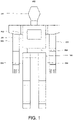
- FIG. 1 is a schematic diagram illustrating an outline configuration of the robot provided with the joint structure according to Embodiment 1.
- a robot 200 includes a body 201, a head 202, a pair of arms 203, a pair of legs 204, and a control device 110 disposed inside the body 201.
- the leg 204 may be connected to a waist 208 which constitutes a part of the body 201 via a joint structure 100 according to Embodiment 1 (described later).
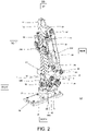
- FIG. 2 is a perspective view illustrating an outline configuration of the joint structure for the robot, provided with a spherical joint according to Embodiment 1. Note that, in FIG. 2 , an up-and-down direction, a front-and-rear direction, and a left-and-right direction in the joint structure for the robot are expressed as an up-and-down direction, a front-and-rear direction, and a left-and-right direction in the drawing.
- the joint structure 100 for the robot according to Embodiment 1 includes a first link 10, a second link 20, a first linear-motion actuator 30A, a second linear-motion actuator 30B, and a joint part 40.
- the first link 10 and the second link 20 are rotatably coupled to each other via the joint part 40. Further, the joint structure 100 for the robot according to Embodiment 1 is configured so that the second link 20 pivots relative to the first link 10 by the first linear-motion actuator 30A and the second linear-motion actuator 30B carrying out a reciprocating motion.
- the first link 10 constitutes a leg part of the robot
- the second link 20 constitutes a foot part of the robot
- the joint part 40 constitutes an ankle joint, it is not limited to this configuration.
- the first link 10 may constitute a lower body part (waist part) of the body of the robot
- the second link 20 may constitute a thigh part of the robot
- the joint part 40 may constitute a hip joint of the robot. If the joint part 40 constitutes the hip joint of the robot, the up-and-down direction illustrated in FIG. 2 will be inverted.
- the first link 10 has a frame member 11 formed in a box shape, an attaching member 12 formed in a strip shape, and a block member 13 formed in a box shape.
- the attaching member 12 is provided to a lower-end part of a front surface of the frame member 11.
- the block member 13 is provided to an upper-end part of a rear surface of the frame member 11.
- the second link 20 has a plate-shaped first member 21 and a pillar-shaped (here, cylindrical) second member 22.
- the second member 22 is provided with a pair of flange parts 23A and 23B.
- the first link 10 and the second link 20 are connected to each other via a block member 50.
- the block member 50 is rotatably attached to a lower-end part of a rear surface of the attaching member 12 via a first shaft member 51 which extends in the front-and-rear direction. Further, the block member 50 is disposed between the pair of flange parts 23A and 23B, and a second shaft member 52 which extends in the left-and-right direction is inserted in these members.
- the second link 20 can pivot, relative to the first link 10, about a roll axis (first shaft member 51) and about a pitch axis (second shaft member 52).
- first linear-motion actuator 30A is disposed at a left side surface of the frame member 11 of the first link 10.
- second linear-motion actuator 30B is disposed at a right side surface of the frame member 11 of the first link 10. Note that, since the second linear-motion actuator 30B has the same configuration as the first linear-motion actuator 30A, detailed description thereof is omitted.
- the first linear-motion actuator 30A has a drive motor (servo motor) 31, a casing 32, a rod member 33, a pulley 34, and a belt 35.
- a ball screw mechanism is disposed inside the casing 32 (not illustrated). Further, a nut which constitutes the ball screw mechanism is connected to the rod member 33.
- the first linear-motion actuator 30A is configured so that rotation of the drive motor 31 is transmitted to the ball screw mechanism via the pulley 34 and the belt 35 to reciprocate the rod member 33 relative to the casing 32.
- the first linear-motion actuator 30A is not limited to the above configuration, and various known linear-motion actuators may be used.
- a base-end part of the first linear-motion actuator 30A (an upper-end part of the casing 32) is rotatably connected to the block member 13 through a third shaft member 53 which extends in the left-and-right direction.
- the joint part 40 is connected to a tip-end part of the first linear-motion actuator 30A (a lower-end part of the rod member 33).
- the joint part 40 has a first link member 1, a second link member 2, and a third link member 3. Note that since the joint part 40 connected to the tip-end part of the second linear-motion actuator 30B is configured similarly to the joint part 40 connected to the tip-end part of the first linear-motion actuator 30A, detailed description thereof is omitted.
- a tip-end part of the first link member 1 is rotatably connected to a lower part of the frame member 11 through a fifth shaft member 55 which extends in the left-and-right direction. Further, a rear-end part of the first link member 1 is formed in a U-shape, and is disposed so as to sandwich the rod member 33 in the left-and-right direction. A fourth shaft member 54 which extends in the left-and-right direction is inserted in the rear-end part of the first link member 1.
- the second link member 2 is formed in a cylindrical shape, and a spherical joint 60 according to Embodiment 1 (see Figs. 3 to 5 ) is disposed at each of an upper-end part and a lower-end part of the second link member 2.
- a mechanism comprised of the second link member 2, and the spherical joint 60 disposed at both the ends of the second link member 2 may also be referred to as a "joint mechanism 41.”
- the joint mechanism 41 (spherical joint 60) will be described later in detail.
- An upper-end part of the joint mechanism 41 is disposed in an interior space of a rear-end part of the rod member 33 formed in the U-shape.
- the rear-end part of the rod member 33 is disposed so as to sandwich the upper-end part of the joint mechanism 41 in the left-and-right direction.
- the rear-end part of the first link member 1 is disposed so as to sandwich the rear-end part of the rod member 33 in the left-and-right direction.
- the fourth shaft member 54 is inserted in the upper-end part of the joint mechanism 41 and the rear-end part of the rod member 33.
- the fourth shaft member 54 is disposed so as to be inserted in the rear-end part of the first link member 1, the rear-end part of the rod member 33, and the upper-end part of the joint mechanism 41.
- a lower-end part of the joint mechanism 41 is disposed in an interior space at the upper-end part of the third link member 3 formed in the U-shape.
- the upper-end part of the third link member 3 is disposed so as to sandwich the lower-end part of the joint mechanism 41 in the left-and-right direction.
- a sixth shaft member 56 is inserted in the lower-end part of the joint mechanism 41 and the upper-end part of the third link member 3. Further, the lower-end part of the third link member 3 is connected to the second member 22 of the second link member 20.
- the joint part 40 can pivot the second link 20 about the pitch axis (second shaft member 52) relative to the first link 10, when the first linear-motion actuator 30A and the second linear-motion actuator 30B both carry out the extending operation or the contracting operation. Further, as one of the first linear-motion actuator 30A and the second linear-motion actuator 30B carries out the extending operation and the other carries out the contracting operation, the joint part 40 can pivot the second link 20 about the roll axis (first shaft member 51) relative to the first link 10.
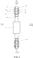
- FIG. 3 is a rear view of the joint mechanism illustrated in FIG. 2 .
- FIG. 4 is a side view of the joint mechanism illustrated in FIG. 2 .
- FIG. 5 is a cross-sectional view of the joint mechanism illustrated in FIG. 3 , taken along a line IV-IV.
- the joint mechanism 41 is provided with the second link member 2 and the spherical joint 60, and the spherical joint 60 is fixed to the second link member 2 by a suitable method.
- a thread may be formed on each of an inner circumferential surface of the second link member 2 and an outer circumferential surface of a connecting part 62B (described later) of the spherical joint 60, and the spherical joint 60 may be threadedly engaged with the second link member 2.
- the spherical joint 60 may be fixed to the second link member 2 by welding.
- the spherical joint 60 has a ball member 61, a socket 62, and a fastening member 63.
- the ball member 61 is formed in a spherical shape.
- the ball member 61 is notched on the side surfaces in the left-and-right direction of the joint structure 100 so that flat surfaces are formed.
- a through-hole 61A is formed in the ball member 61 so as to extend in the left-and-right direction, and the fourth shaft member 54 or the sixth shaft member 56 is inserted in the through-hole 61A.
- the socket 62 has a cage part 62A where an inner circumferential surface which spherically contacts the ball member 61 is formed, and the bar-shaped connecting part 62B formed so as to extend from the outer circumferential surface of the cage part 62A.
- a slit-shaped opening 6C is formed in the cage part 62A.
- the cage part 62A is formed in a C-shape (or a U-shape).
- the opening 6C is formed in a part of the inner circumferential surface other than a part where the largest load is applied.
- the part of the inner circumferential surface where the largest load is applied may be a part located in the extending direction of the connecting part 62B.
- the part of the inner circumferential surface where the largest load is applied may be a part located in the reciprocating direction (the up-and-down direction of the joint part 40) of the rod member 33 of the first linear-motion actuator 30A (second linear-motion actuator 30B).
- the spherical joint 60 may be disposed so that the opening 6C is located outward of the robot 200.
- the spherical joint 60 may be disposed at the robot 200 so that the opening 6C is located forward or rearward.
- the spherical joint 60 may be disposed at the robot 200 so that the opening 6C is located leftward or rightward.
- the opening 6C may be formed in the cage part 62A so as to be located in a direction perpendicular to the extending direction of the connecting part 62B.
- protrusions 6A and 6B are provided in both end parts of the cage part 62A which form the opening 6C so as to extend rearward.
- the protrusions 6A and 6B are provided so as to protrude from the outer circumferential surface of the cage part 62A.
- through-holes are formed in the protrusions 6A and 6B so as to extend in the up-and-down direction and so as not to communicate with the inner circumferential surface of the cage part 62A, and the fastening member 63 is inserted in the through-holes.
- the fastening member 63 can reduce the space volume of the opening 6C by bringing the protrusions 6A and 6B closer to each other. Therefore, a radius of curvature of the inner circumferential surface of the cage part 62A can be reduced.
- the fastening member 63 is configured so as not to contact the ball member 61. Therefore, the movement of the ball member 61 will not be restricted.
- the fastening member 63 which reduces the space of the opening 6C is disposed at the protrusions 6A and 6B of the cage part 62A.
- the rattling can be eliminated by the fastening member 63 reducing the radius of curvature of the inner circumferential surface of the cage part 62A. Further, before the rattling occurs, the rattling can be suppressed by the fastening member 63 reducing the radius of curvature of the inner circumferential surface of the cage part 62A.
- the spherical joint 60 and the joint structure 100 for the robot having the spherical joint 60 according to Embodiment 1 is configured so that the fastening member 63 does not contact the ball member 61. Therefore, the movement of the ball member 61 will not be restricted.
- the opening 6C is located outward of the robot 200.
- a spherical joint according to Embodiment 2 is configured, in the spherical joint according to Embodiment 1, so that the socket is divided into two or more, and the fastening member couples the divided socket.
- FIG. 6 is a cross-sectional view illustrating an outline configuration of a joint mechanism having the spherical joint according to Embodiment 2.
- the spherical joint 60 according to Embodiment 2 is the same in the fundamental configuration as the spherical joint 60 according to Embodiment 1, but it differs in that the socket 62 is divided into two or more (here, two). In detail, the cage part 62A of the socket 62 is divided into upper and lower parts.
- the protrusions 6A and 6B are provided also in the front part of the cage part 62A so as to protrude forward, and the opening 6C is formed between the protrusions 6A and 6B. Further, the fastening member 63 is disposed also at the front protrusions 6A and 6B.
- the opening 6C is formed in both the front part and the rear part of the cage part 62A, the opening 6C may be formed only in either one of them.
- the spherical joint 60 according to Embodiment 2 configured in this way can also obtain similar operation and effects to the spherical joint 60 according to Embodiment 1.
- the spherical joint and the joint structure for the robot having the spherical joint of the present disclosure can eliminate or suppress rattling, it is useful.
Landscapes
- Engineering & Computer Science (AREA)
- General Engineering & Computer Science (AREA)
- Mechanical Engineering (AREA)
- Robotics (AREA)
- Manipulator (AREA)
- Pivots And Pivotal Connections (AREA)
Abstract
Description
- The present disclosure relates to a spherical joint and a joint structure for a robot having the same.
- Drive mechanisms used for a joint structure of a robot are known (for example, see Patent Document 1). A drive mechanism disclosed in
Patent Document 1 is, for example, to drive a joint part, such as an ankle joint of a humanoid robot. In this drive mechanism, a tip-end part of a first link member and a base-end part of a second link member, which constitute the ankle joint, are coupled through a spherical joint. - [Patent Document 1]
WO2017/094922A1 - However, even in the drive mechanism disclosed in
Patent Document 1, the load of the robot may be applied to the spherical joint to cause rattling. In detail, when an inner circumferential surface of a socket which spherically contacts a ball member which constitutes the spherical joint is worn out, or when grease filled up inside the socket ran out, the rattling may be caused in the spherical joint. - The present disclosure is to solve the above-described conventional problem, and one purpose thereof is to provide a spherical joint, and a joint structure for a robot, having the spherical joint, capable of reducing a radius of curvature of an inner circumferential surface of a socket when rattling occurs to increase a contacting area with a ball member so as to eliminate the rattling or suppressing the rattling.
- In order to solve the conventional problem, a spherical joint according to the present disclosure includes a ball member, and a socket having an inner circumferential surface configured to spherically contact the ball member. The socket includes a cage part forming the inner circumferential surface and having an opening, and a connecting part provided to the cage part. A fastening member is disposed at the cage part, the fastening member being configured to reduce a space of the opening and not to contact the ball member. The opening is formed in a part of the inner circumferential surface other than a part where the largest load is applied.
- According to this, even when rattling occurs between the ball member and the inner circumferential surface of the socket, the rattling can be eliminated or suppressed.
- Moreover, a joint structure for a robot according to the present disclosure includes the spherical joint described above.
- According to this, even when rattling occurs between the ball member and the inner circumferential surface of the socket, the rattling can be eliminated or suppressed.
- The above purpose, other purposes, features, and advantages of the present disclosure will be made clear from the following detailed description of suitable embodiments with reference to the accompanying drawings.
- According to the spherical joint, and the joint structure for the robot, having the spherical joint, even when rattling occurs between the ball member and the inner circumferential surface of the socket, the rattling can be eliminated or suppressed.
-
-
FIG. 1 is a schematic diagram illustrating an outline configuration of a robot provided with a joint structure according toEmbodiment 1. -
FIG. 2 is a perspective view illustrating an outline configuration of the joint structure for the robot, provided with a spherical joint according toEmbodiment 1. -
FIG. 3 is a rear view of a joint mechanism illustrated inFIG. 2 . -
FIG. 4 is a side view of the joint mechanism illustrated inFIG. 2 . -
FIG. 5 is a cross-sectional view of the joint mechanism illustrated inFIG. 3 , taken along a line IV-IV. -
FIG. 6 is a cross-sectional view illustrating an outline configuration of a joint mechanism having a spherical joint according toEmbodiment 2. - Hereinafter, embodiments of the present disclosure will be described with reference to the drawings. Note that, throughout the drawings, the same reference characters are given to the same or corresponding parts to omit redundant description. Moreover, throughout the drawings, components are selectively illustrated for explaining the present disclosure, and illustration of other components may be omitted. The present disclosure is not limited to the following embodiments.
- A spherical joint according to
Embodiment 1 includes a ball member and a socket having an inner circumferential surface which spherically contacts the ball member. The socket has a cage part forming the inner circumferential surface and having an opening, and a bar-shaped connecting part provided to the cage part. In the cage part, a fastening member configured so as to reduce a space of the opening and not to contact the ball member is disposed, and the opening is formed in a part of the inner circumferential surface other than a part where the largest load is applied. - Further, in the spherical joint according to
Embodiment 1, the cage part of the socket is formed in a C-shape or a U-shape, and the fastening member may be configured to bring both ends of the cage part closer to each other. - Moreover, in the spherical joint according to
Embodiment 1, the part of the inner circumferential surface of the socket where the largest load is applied may be a part located in an extending direction of the connecting part. - A joint structure for the robot according to
Embodiment 1 is provided with the spherical joint with any one of the structures described above. - In the joint structure for the robot according to
Embodiment 1, the spherical joint may be disposed so that the opening is located outward of the robot. - The joint structure for the robot according to
Embodiment 1 may be used for an ankle joint or a hip joint of a humanoid robot. - Below, examples of the spherical joint and the joint structure for the robot having the spherical joint according to
Embodiment 1 are described with reference toFigs. 1 to 5 . - First, a configuration of the robot provided with the joint structure according to
Embodiment 1 is described with reference toFIG. 1 . -
FIG. 1 is a schematic diagram illustrating an outline configuration of the robot provided with the joint structure according toEmbodiment 1. - As illustrated in
FIG. 1 , arobot 200 includes abody 201, ahead 202, a pair ofarms 203, a pair oflegs 204, and a control device 110 disposed inside thebody 201. Theleg 204 may be connected to awaist 208 which constitutes a part of thebody 201 via ajoint structure 100 according to Embodiment 1 (described later). -
FIG. 2 is a perspective view illustrating an outline configuration of the joint structure for the robot, provided with a spherical joint according toEmbodiment 1. Note that, inFIG. 2 , an up-and-down direction, a front-and-rear direction, and a left-and-right direction in the joint structure for the robot are expressed as an up-and-down direction, a front-and-rear direction, and a left-and-right direction in the drawing. - As illustrated in
FIG. 2 , thejoint structure 100 for the robot according toEmbodiment 1 includes afirst link 10, asecond link 20, a first linear-motion actuator 30A, a second linear-motion actuator 30B, and ajoint part 40. - The
first link 10 and thesecond link 20 are rotatably coupled to each other via thejoint part 40. Further, thejoint structure 100 for the robot according toEmbodiment 1 is configured so that thesecond link 20 pivots relative to thefirst link 10 by the first linear-motion actuator 30A and the second linear-motion actuator 30B carrying out a reciprocating motion. - Note that, although in the
joint structure 100 for the robot according to Embodiment 1 thefirst link 10 constitutes a leg part of the robot, thesecond link 20 constitutes a foot part of the robot, and thejoint part 40 constitutes an ankle joint, it is not limited to this configuration. - For example, in the
joint structure 100, thefirst link 10 may constitute a lower body part (waist part) of the body of the robot, thesecond link 20 may constitute a thigh part of the robot, and thejoint part 40 may constitute a hip joint of the robot. If thejoint part 40 constitutes the hip joint of the robot, the up-and-down direction illustrated inFIG. 2 will be inverted. - The
first link 10 has aframe member 11 formed in a box shape, an attachingmember 12 formed in a strip shape, and ablock member 13 formed in a box shape. The attachingmember 12 is provided to a lower-end part of a front surface of theframe member 11. Theblock member 13 is provided to an upper-end part of a rear surface of theframe member 11. - Further, the
second link 20 has a plate-shapedfirst member 21 and a pillar-shaped (here, cylindrical)second member 22. Thesecond member 22 is provided with a pair offlange parts - The
first link 10 and thesecond link 20 are connected to each other via ablock member 50. In detail, theblock member 50 is rotatably attached to a lower-end part of a rear surface of the attachingmember 12 via afirst shaft member 51 which extends in the front-and-rear direction. Further, theblock member 50 is disposed between the pair offlange parts second shaft member 52 which extends in the left-and-right direction is inserted in these members. - Therefore, the
second link 20 can pivot, relative to thefirst link 10, about a roll axis (first shaft member 51) and about a pitch axis (second shaft member 52). - Further, the first linear-
motion actuator 30A is disposed at a left side surface of theframe member 11 of thefirst link 10. Similarly, the second linear-motion actuator 30B is disposed at a right side surface of theframe member 11 of thefirst link 10. Note that, since the second linear-motion actuator 30B has the same configuration as the first linear-motion actuator 30A, detailed description thereof is omitted. - Here, the first linear-
motion actuator 30A has a drive motor (servo motor) 31, acasing 32, arod member 33, apulley 34, and abelt 35. A ball screw mechanism is disposed inside the casing 32 (not illustrated). Further, a nut which constitutes the ball screw mechanism is connected to therod member 33. The first linear-motion actuator 30A is configured so that rotation of thedrive motor 31 is transmitted to the ball screw mechanism via thepulley 34 and thebelt 35 to reciprocate therod member 33 relative to thecasing 32. Note that the first linear-motion actuator 30A is not limited to the above configuration, and various known linear-motion actuators may be used. - Further, a base-end part of the first linear-
motion actuator 30A (an upper-end part of the casing 32) is rotatably connected to theblock member 13 through athird shaft member 53 which extends in the left-and-right direction. Thejoint part 40 is connected to a tip-end part of the first linear-motion actuator 30A (a lower-end part of the rod member 33). - The
joint part 40 has afirst link member 1, asecond link member 2, and athird link member 3. Note that since thejoint part 40 connected to the tip-end part of the second linear-motion actuator 30B is configured similarly to thejoint part 40 connected to the tip-end part of the first linear-motion actuator 30A, detailed description thereof is omitted. - A tip-end part of the
first link member 1 is rotatably connected to a lower part of theframe member 11 through afifth shaft member 55 which extends in the left-and-right direction. Further, a rear-end part of thefirst link member 1 is formed in a U-shape, and is disposed so as to sandwich therod member 33 in the left-and-right direction. Afourth shaft member 54 which extends in the left-and-right direction is inserted in the rear-end part of thefirst link member 1. - The
second link member 2 is formed in a cylindrical shape, and a spherical joint 60 according to Embodiment 1 (seeFigs. 3 to 5 ) is disposed at each of an upper-end part and a lower-end part of thesecond link member 2. Note that, below, a mechanism comprised of thesecond link member 2, and the spherical joint 60 disposed at both the ends of thesecond link member 2 may also be referred to as a "joint mechanism 41." The joint mechanism 41 (spherical joint 60) will be described later in detail. - An upper-end part of the
joint mechanism 41 is disposed in an interior space of a rear-end part of therod member 33 formed in the U-shape. In other words, the rear-end part of therod member 33 is disposed so as to sandwich the upper-end part of thejoint mechanism 41 in the left-and-right direction. As described above, the rear-end part of thefirst link member 1 is disposed so as to sandwich the rear-end part of therod member 33 in the left-and-right direction. - The
fourth shaft member 54 is inserted in the upper-end part of thejoint mechanism 41 and the rear-end part of therod member 33. In other words, thefourth shaft member 54 is disposed so as to be inserted in the rear-end part of thefirst link member 1, the rear-end part of therod member 33, and the upper-end part of thejoint mechanism 41. - A lower-end part of the
joint mechanism 41 is disposed in an interior space at the upper-end part of thethird link member 3 formed in the U-shape. In other words, the upper-end part of thethird link member 3 is disposed so as to sandwich the lower-end part of thejoint mechanism 41 in the left-and-right direction. Asixth shaft member 56 is inserted in the lower-end part of thejoint mechanism 41 and the upper-end part of thethird link member 3. Further, the lower-end part of thethird link member 3 is connected to thesecond member 22 of thesecond link member 20. - According to the above configuration, the
joint part 40 can pivot thesecond link 20 about the pitch axis (second shaft member 52) relative to thefirst link 10, when the first linear-motion actuator 30A and the second linear-motion actuator 30B both carry out the extending operation or the contracting operation. Further, as one of the first linear-motion actuator 30A and the second linear-motion actuator 30B carries out the extending operation and the other carries out the contracting operation, thejoint part 40 can pivot thesecond link 20 about the roll axis (first shaft member 51) relative to thefirst link 10. - Next, a configuration of the
joint mechanism 41 is described with reference toFigs. 2 to 5 . -
FIG. 3 is a rear view of the joint mechanism illustrated inFIG. 2 .FIG. 4 is a side view of the joint mechanism illustrated inFIG. 2 .FIG. 5 is a cross-sectional view of the joint mechanism illustrated inFIG. 3 , taken along a line IV-IV. - As illustrated in
Figs. 3 to 5 , thejoint mechanism 41 is provided with thesecond link member 2 and the spherical joint 60, and the spherical joint 60 is fixed to thesecond link member 2 by a suitable method. For example, a thread may be formed on each of an inner circumferential surface of thesecond link member 2 and an outer circumferential surface of a connectingpart 62B (described later) of the spherical joint 60, and the spherical joint 60 may be threadedly engaged with thesecond link member 2. Alternatively, for example, the spherical joint 60 may be fixed to thesecond link member 2 by welding. - The spherical joint 60 has a
ball member 61, asocket 62, and afastening member 63. Theball member 61 is formed in a spherical shape. InEmbodiment 1, theball member 61 is notched on the side surfaces in the left-and-right direction of thejoint structure 100 so that flat surfaces are formed. A through-hole 61A is formed in theball member 61 so as to extend in the left-and-right direction, and thefourth shaft member 54 or thesixth shaft member 56 is inserted in the through-hole 61A. - The
socket 62 has acage part 62A where an inner circumferential surface which spherically contacts theball member 61 is formed, and the bar-shaped connectingpart 62B formed so as to extend from the outer circumferential surface of thecage part 62A. - A slit-shaped
opening 6C is formed in thecage part 62A. In other words, thecage part 62A is formed in a C-shape (or a U-shape). The opening 6C is formed in a part of the inner circumferential surface other than a part where the largest load is applied. - Here, the part of the inner circumferential surface where the largest load is applied may be a part located in the extending direction of the connecting
part 62B. Alternatively, the part of the inner circumferential surface where the largest load is applied may be a part located in the reciprocating direction (the up-and-down direction of the joint part 40) of therod member 33 of the first linear-motion actuator 30A (second linear-motion actuator 30B). - Note that the spherical joint 60 may be disposed so that the opening 6C is located outward of the
robot 200. In detail, if therobot 200 is a humanoid robot, the spherical joint 60 may be disposed at therobot 200 so that the opening 6C is located forward or rearward. Alternatively, if therobot 200 is a humanoid robot, the spherical joint 60 may be disposed at therobot 200 so that the opening 6C is located leftward or rightward. - Alternatively, the
opening 6C may be formed in thecage part 62A so as to be located in a direction perpendicular to the extending direction of the connectingpart 62B. - Further,
protrusions cage part 62A which form the opening 6C so as to extend rearward. Theprotrusions cage part 62A. Further, through-holes are formed in theprotrusions cage part 62A, and thefastening member 63 is inserted in the through-holes. - The
fastening member 63 can reduce the space volume of the opening 6C by bringing theprotrusions cage part 62A can be reduced. - Further, the
fastening member 63 is configured so as not to contact theball member 61. Therefore, the movement of theball member 61 will not be restricted. - In the thus-configured spherical joint 60 according to
Embodiment 1 and thejoint structure 100 for the robot having the spherical joint 60, thefastening member 63 which reduces the space of the opening 6C is disposed at theprotrusions cage part 62A. - Therefore, even when rattling occurs in the spherical joint due to wearing of the inner circumferential surface of the
cage part 62A and running out of grease filled up inside thesocket 62, the rattling can be eliminated by thefastening member 63 reducing the radius of curvature of the inner circumferential surface of thecage part 62A. Further, before the rattling occurs, the rattling can be suppressed by thefastening member 63 reducing the radius of curvature of the inner circumferential surface of thecage part 62A. - Moreover, the spherical joint 60 and the
joint structure 100 for the robot having the spherical joint 60 according toEmbodiment 1 is configured so that thefastening member 63 does not contact theball member 61. Therefore, the movement of theball member 61 will not be restricted. - Further, in the spherical joint 60 and the
joint structure 100 for the robot having the spherical joint 60 according toEmbodiment 1, the opening 6C is located outward of therobot 200. - Therefore, it can be suppressed that the
protrusions robot 200. Further, since thefastening member 63 can be accessed easily, maintenance of the robot 200 (spherical joint 60) can be performed easily. - A spherical joint according to
Embodiment 2 is configured, in the spherical joint according toEmbodiment 1, so that the socket is divided into two or more, and the fastening member couples the divided socket. - Below, one example of the spherical joint according to
Embodiment 2 is described with reference toFIG. 5 . -
FIG. 6 is a cross-sectional view illustrating an outline configuration of a joint mechanism having the spherical joint according toEmbodiment 2. - As illustrated in
FIG. 6 , the spherical joint 60 according toEmbodiment 2 is the same in the fundamental configuration as the spherical joint 60 according toEmbodiment 1, but it differs in that thesocket 62 is divided into two or more (here, two). In detail, thecage part 62A of thesocket 62 is divided into upper and lower parts. - Further, in the spherical joint 60 according to
Embodiment 2, theprotrusions cage part 62A so as to protrude forward, and theopening 6C is formed between theprotrusions fastening member 63 is disposed also at thefront protrusions - Note that, although in
Embodiment 2 theopening 6C is formed in both the front part and the rear part of thecage part 62A, theopening 6C may be formed only in either one of them. - The spherical joint 60 according to
Embodiment 2 configured in this way can also obtain similar operation and effects to the spherical joint 60 according toEmbodiment 1. - It is apparent for the person skilled in the art that many improvements or other embodiments of the present disclosure are possible from the above description. Therefore, the above description is to be interpreted only as illustration, and it is provided in order to teach the person skilled in the art the best mode that implements the present disclosure. The details of the structures and/or the functions may be changed substantially, without departing from the present disclosure.
- Since the spherical joint and the joint structure for the robot having the spherical joint of the present disclosure can eliminate or suppress rattling, it is useful.
-
- 1
- First Link Member
- 2
- Second Link Member
- 3
- Third Link Member
- 6A
- Protrusion
- 6B
- Protrusion
- 6C
- Opening
- 10
- First Link
- 11
- Frame Member
- 12
- Attaching Member
- 13
- Block Member
- 20
- Second Link
- 21
- First Member
- 22
- Second Member
- 23A
- Flange Part
- 23B
- Flange Part
- 30A
- First Linear-motion Actuator
- 30B
- Second Linear-motion Actuator
- 31
- Drive Motor
- 32
- Casing
- 33
- Rod Member
- 34
- Pulley
- 35
- Belt
- 40
- Joint Part
- 41
- Joint Mechanism
- 50
- Block Member
- 51
- First Shaft Member
- 52
- Second Shaft Member
- 53
- Third Shaft Member
- 54
- Fourth Shaft Member
- 55
- Fifth Shaft Member
- 56
- Sixth Shaft Member
- 60
- Spherical Joint
- 61
- Ball Member
- 61A
- Through-hole
- 62
- Socket
- 62A
- Cage Part
- 63
- Fastening Member
- 100
- Joint Structure
- 110
- Control Device
- 200
- Robot
- 201
- Body
- 202
- Head
- 203
- Arm
- 204
- Leg
- 208
- Waist
Claims (7)
- A spherical joint, comprising:a ball member; anda socket having an inner circumferential surface configured to spherically contact the ball member,wherein the socket includes a cage part forming the inner circumferential surface and having an opening, and a connecting part provided to the cage part,wherein a fastening member is disposed at the cage part, the fastening member being configured to reduce a space of the opening and not to contact the ball member, andwherein the opening is formed in a part of the inner circumferential surface other than a part where the largest load is applied.
- The spherical joint of claim 1, wherein the cage part of the socket is formed in a C-shape, and the fastening member is configured to bring both ends of the cage part closer to each other.
- The spherical joint of claim 1, wherein the socket is divided into two or more, and
wherein the fastening member is configured to couple the divided sockets. - The spherical joint of any one of claims 1 to 3, wherein the connecting part is formed in a bar shape, and
wherein the part of the inner circumferential surface of the socket where the largest load is applied is a part located in an extending direction of the connecting part. - A joint structure for a robot, comprising the spherical joint of any one of claims 1 to 4.
- The joint structure of claim 5, wherein the spherical joint is disposed so that the opening is located outward of the robot.
- The joint structure of claim 6, wherein the joint structure is used for an ankle joint or a hip joint of a humanoid robot.
Applications Claiming Priority (2)
| Application Number | Priority Date | Filing Date | Title |
|---|---|---|---|
| JP2019159743A JP7372786B2 (en) | 2019-09-02 | 2019-09-02 | Spherical joint and robot joint structure equipped with the same |
| PCT/JP2020/033119 WO2021045057A1 (en) | 2019-09-02 | 2020-09-01 | Spherical joint and robot joint structure comprising same |
Publications (2)
| Publication Number | Publication Date |
|---|---|
| EP4026669A1 true EP4026669A1 (en) | 2022-07-13 |
| EP4026669A4 EP4026669A4 (en) | 2023-11-01 |
Family
ID=74846868
Family Applications (1)
| Application Number | Title | Priority Date | Filing Date |
|---|---|---|---|
| EP20860169.0A Withdrawn EP4026669A4 (en) | 2019-09-02 | 2020-09-01 | SPHERICAL JOINT AND ROBOT JOINT STRUCTURE INCLUDING SAME |
Country Status (6)
| Country | Link |
|---|---|
| US (1) | US12343863B2 (en) |
| EP (1) | EP4026669A4 (en) |
| JP (1) | JP7372786B2 (en) |
| KR (1) | KR20220051381A (en) |
| CN (1) | CN114007822A (en) |
| WO (1) | WO2021045057A1 (en) |
Family Cites Families (36)
| Publication number | Priority date | Publication date | Assignee | Title |
|---|---|---|---|---|
| FR364821A (en) * | 1905-05-11 | 1906-08-28 | Buessing H | Adjustable universal joint |
| GB136048A (en) * | 1919-03-10 | 1919-12-11 | James Scott Knight | A Detachable and Clamping Ball and Socket Joint. |
| GB294456A (en) * | 1928-03-10 | 1928-07-26 | Carlos Jaramillo Borda | Improvements in leveling devices |
| FR689262A (en) * | 1929-02-04 | 1930-09-04 | Emde & Meissner Metallwarenfab | Articulated joint |
| US2513027A (en) * | 1948-04-21 | 1950-06-27 | Kruczek Andrew | Ball and socket type support |
| DE922450C (en) * | 1953-07-03 | 1955-01-17 | Famo Vertriebs Ges M B H | Ball joint that can be locked by tensioning |
| US3522975A (en) * | 1967-09-25 | 1970-08-04 | Charles S White | Bearing |
| US3597025A (en) * | 1969-05-15 | 1971-08-03 | Caterpillar Tractor Co | Multipart bearing liner |
| FR2606472B1 (en) * | 1986-11-12 | 1991-05-17 | Prouvost Sa | ARTICULATION DEVICE BETWEEN TWO PARTS, ESPECIALLY BETWEEN TWO MANNEQUIN ELEMENTS |
| FR2620345A1 (en) * | 1987-09-15 | 1989-03-17 | Champel Robert | All-terrain stilts with slant compensation |
| US4780000A (en) * | 1987-09-23 | 1988-10-25 | Mts Systems Corporation | Adjustable rod end |
| US4980805A (en) * | 1988-12-16 | 1990-12-25 | Mag Instrument, Inc. | Flashlight holder clamp assembly |
| DE9301268U1 (en) * | 1993-01-30 | 1993-03-11 | Fa. Carl Zeiss, 7920 Heidenheim | Articulated suspension |
| FR2719455B1 (en) * | 1994-05-06 | 1996-06-07 | Promod | Mannequin representing the body of a human being. |
| AUPP294698A0 (en) | 1998-04-15 | 1998-05-07 | Gray, Bruce | Removable ball joint |
| RU2241595C1 (en) * | 2000-11-17 | 2004-12-10 | Хонда Гикен Когио Кабусики Кайся | Leg assembly of walking robot |
| JP2004052911A (en) * | 2002-07-19 | 2004-02-19 | Toshio Tomioka | Universal joint and retainer using the same |
| US6988696B2 (en) * | 2003-06-03 | 2006-01-24 | Delaware Capital Formation, Inc. | Mounting member with snap in swivel member |
| US7320555B2 (en) * | 2005-10-14 | 2008-01-22 | Sercomm Corporation | Cardan shaft structure with tightness adjustable functions |
| EP2147854B1 (en) * | 2008-07-16 | 2011-02-16 | Torqeedo GmbH | Mounting for an outboard motor |
| JP2011156146A (en) | 2010-02-01 | 2011-08-18 | Univ Of Tokyo | Force transmission device |
| US9157471B2 (en) * | 2011-09-26 | 2015-10-13 | Kenneth Alvin Jungeberg | Friction locking spherical joint |
| US10012261B2 (en) | 2011-09-26 | 2018-07-03 | Kenneth Alvin Jungeberg | Method and apparatus for releasably immobilizing an attachment to an external object |
| JP5722747B2 (en) * | 2011-10-24 | 2015-05-27 | Thk株式会社 | Robot joint structure and robot incorporating this joint structure |
| US9924969B2 (en) * | 2012-09-04 | 2018-03-27 | Zimmer, Inc. | External fixation |
| ITVR20130006A1 (en) * | 2013-01-11 | 2014-07-12 | Tecres Spa | ADJUSTABLE SPHERICAL JOINT |
| WO2014138503A1 (en) * | 2013-03-06 | 2014-09-12 | Roller Bearing Company Of America, Inc. | Linkage apparatus having a low profile asymmetrical head |
| US9157474B2 (en) * | 2013-09-30 | 2015-10-13 | Bell Helicopter Textron Inc. | System and method of monitoring wear in a bearing |
| JP6087329B2 (en) * | 2014-09-19 | 2017-03-01 | Thk株式会社 | Rotation drive mechanism in robot |
| US10119562B2 (en) * | 2014-12-16 | 2018-11-06 | Itt Manufacturing Enterprises Llc | One-hand operable end fitting connector assembly |
| DE202015106815U1 (en) * | 2015-09-17 | 2016-12-20 | Rk Rose + Krieger Gmbh Verbindungs- Und Positioniersysteme | Joint arrangement for positioning components |
| GB2544504A (en) * | 2015-11-18 | 2017-05-24 | Smidsy Ltd | Adjustable bracket |
| CN122040828A (en) * | 2015-12-03 | 2026-05-15 | 川崎重工业株式会社 | 2-DOF drive mechanism |
| CN109551508A (en) * | 2017-09-25 | 2019-04-02 | 浙江道夫机器人科技有限公司 | A kind of modular structure and robot for robot |
| DE102019119187A1 (en) * | 2019-07-16 | 2020-07-23 | ECO Holding 1 GmbH | Connecting rod for an internal combustion engine with variable compression |
| US20230003251A1 (en) * | 2020-05-12 | 2023-01-05 | Chien-Ting Lin | Ball head |
-
2019
- 2019-09-02 JP JP2019159743A patent/JP7372786B2/en active Active
-
2020
- 2020-09-01 KR KR1020227009886A patent/KR20220051381A/en not_active Ceased
- 2020-09-01 EP EP20860169.0A patent/EP4026669A4/en not_active Withdrawn
- 2020-09-01 CN CN202080042288.2A patent/CN114007822A/en active Pending
- 2020-09-01 WO PCT/JP2020/033119 patent/WO2021045057A1/en not_active Ceased
- 2020-09-01 US US17/638,256 patent/US12343863B2/en active Active
Also Published As
| Publication number | Publication date |
|---|---|
| EP4026669A4 (en) | 2023-11-01 |
| WO2021045057A1 (en) | 2021-03-11 |
| US20220402148A1 (en) | 2022-12-22 |
| US12343863B2 (en) | 2025-07-01 |
| JP2021038779A (en) | 2021-03-11 |
| JP7372786B2 (en) | 2023-11-01 |
| KR20220051381A (en) | 2022-04-26 |
| CN114007822A (en) | 2022-02-01 |
Similar Documents
| Publication | Publication Date | Title |
|---|---|---|
| KR102458112B1 (en) | Drive machanism of two degrees of freedom | |
| RU2570983C2 (en) | Vehicle and spherical joint for vehicle front suspension | |
| US10836425B2 (en) | Wheel steering system | |
| US7441614B2 (en) | Legged mobile robot | |
| JP2003002028A (en) | Suspension structure | |
| US20180297216A1 (en) | Universal coupling and robot joint structure | |
| JP2011098425A (en) | Leg for human type walking robot | |
| CN118357959A (en) | A connecting rod parallel wrist joint for a robotic arm, a seven-degree-of-freedom high-load robotic arm, and an electro-hydraulic hybrid drive humanoid robot | |
| US12343863B2 (en) | Spherical joint and joint structure for robot having the same | |
| KR102473636B1 (en) | robot joint structure | |
| CN120440153B (en) | Leg structure and biped robot | |
| KR102679106B1 (en) | Robot joint structure | |
| US3053556A (en) | Idler arm ball joint | |
| EP0441228A1 (en) | Suspension for steering vehicle wheel improved in connection of stabilizer | |
| JPH02144213A (en) | Stabilizer connecting rod for automobile suspension device | |
| US12466502B1 (en) | Method and system for improving stability in a legged robot | |
| CN224241141U (en) | Leg structure and biped robot | |
| CN119503047B (en) | A humanoid robot and its knee joint with variable stiffness and variable reduction ratio functions | |
| JP6705658B2 (en) | Legged mobile robot | |
| CN223657049U (en) | A joint component and robot | |
| CN120003615B (en) | A multi-motion mode robot | |
| CN115771579B (en) | robot | |
| KR20250061701A (en) | Wearable robot | |
| CN120327650A (en) | A humanoid robot calf structure and leg mechanism | |
| CN121733596A (en) | Support device for robot and robot |
Legal Events
| Date | Code | Title | Description |
|---|---|---|---|
| STAA | Information on the status of an ep patent application or granted ep patent |
Free format text: STATUS: THE INTERNATIONAL PUBLICATION HAS BEEN MADE |
|
| PUAI | Public reference made under article 153(3) epc to a published international application that has entered the european phase |
Free format text: ORIGINAL CODE: 0009012 |
|
| STAA | Information on the status of an ep patent application or granted ep patent |
Free format text: STATUS: REQUEST FOR EXAMINATION WAS MADE |
|
| 17P | Request for examination filed |
Effective date: 20220215 |
|
| AK | Designated contracting states |
Kind code of ref document: A1 Designated state(s): AL AT BE BG CH CY CZ DE DK EE ES FI FR GB GR HR HU IE IS IT LI LT LU LV MC MK MT NL NO PL PT RO RS SE SI SK SM TR |
|
| DAV | Request for validation of the european patent (deleted) | ||
| DAX | Request for extension of the european patent (deleted) | ||
| A4 | Supplementary search report drawn up and despatched |
Effective date: 20231005 |
|
| RIC1 | Information provided on ipc code assigned before grant |
Ipc: B25J 17/02 20060101ALI20230928BHEP Ipc: F16C 9/06 20060101ALI20230928BHEP Ipc: F16C 11/10 20060101ALI20230928BHEP Ipc: F16C 11/06 20060101ALI20230928BHEP Ipc: B25J 17/00 20060101AFI20230928BHEP |
|
| STAA | Information on the status of an ep patent application or granted ep patent |
Free format text: STATUS: EXAMINATION IS IN PROGRESS |
|
| 17Q | First examination report despatched |
Effective date: 20251212 |
|
| STAA | Information on the status of an ep patent application or granted ep patent |
Free format text: STATUS: THE APPLICATION HAS BEEN WITHDRAWN |
|
| 18W | Application withdrawn |
Effective date: 20260311 |