EP4026503A1 - Devices, systems, and methods of manufacturing fluid-cooled ultrasonic surgical instruments - Google Patents
Devices, systems, and methods of manufacturing fluid-cooled ultrasonic surgical instruments Download PDFInfo
- Publication number
- EP4026503A1 EP4026503A1 EP22150452.5A EP22150452A EP4026503A1 EP 4026503 A1 EP4026503 A1 EP 4026503A1 EP 22150452 A EP22150452 A EP 22150452A EP 4026503 A1 EP4026503 A1 EP 4026503A1
- Authority
- EP
- European Patent Office
- Prior art keywords
- distal
- ultrasonic
- proximal
- waveguide body
- lumen
- Prior art date
- Legal status (The legal status is an assumption and is not a legal conclusion. Google has not performed a legal analysis and makes no representation as to the accuracy of the status listed.)
- Granted
Links
Images




Classifications
-
- A—HUMAN NECESSITIES
- A61—MEDICAL OR VETERINARY SCIENCE; HYGIENE
- A61B—DIAGNOSIS; SURGERY; IDENTIFICATION
- A61B17/00—Surgical instruments, devices or methods
- A61B17/32—Surgical cutting instruments
- A61B17/320068—Surgical cutting instruments using mechanical vibrations, e.g. ultrasonic
-
- A—HUMAN NECESSITIES
- A61—MEDICAL OR VETERINARY SCIENCE; HYGIENE
- A61B—DIAGNOSIS; SURGERY; IDENTIFICATION
- A61B17/00—Surgical instruments, devices or methods
- A61B17/32—Surgical cutting instruments
- A61B17/320068—Surgical cutting instruments using mechanical vibrations, e.g. ultrasonic
- A61B17/320092—Surgical cutting instruments using mechanical vibrations, e.g. ultrasonic with additional movable means for clamping or cutting tissue, e.g. with a pivoting jaw
-
- A—HUMAN NECESSITIES
- A61—MEDICAL OR VETERINARY SCIENCE; HYGIENE
- A61B—DIAGNOSIS; SURGERY; IDENTIFICATION
- A61B17/00—Surgical instruments, devices or methods
- A61B2017/00526—Methods of manufacturing
-
- A—HUMAN NECESSITIES
- A61—MEDICAL OR VETERINARY SCIENCE; HYGIENE
- A61B—DIAGNOSIS; SURGERY; IDENTIFICATION
- A61B17/00—Surgical instruments, devices or methods
- A61B2017/00535—Surgical instruments, devices or methods pneumatically or hydraulically operated
- A61B2017/00539—Surgical instruments, devices or methods pneumatically or hydraulically operated hydraulically
-
- A—HUMAN NECESSITIES
- A61—MEDICAL OR VETERINARY SCIENCE; HYGIENE
- A61B—DIAGNOSIS; SURGERY; IDENTIFICATION
- A61B17/00—Surgical instruments, devices or methods
- A61B17/32—Surgical cutting instruments
- A61B2017/320056—Tunnelers
-
- A—HUMAN NECESSITIES
- A61—MEDICAL OR VETERINARY SCIENCE; HYGIENE
- A61B—DIAGNOSIS; SURGERY; IDENTIFICATION
- A61B17/00—Surgical instruments, devices or methods
- A61B17/32—Surgical cutting instruments
- A61B17/320068—Surgical cutting instruments using mechanical vibrations, e.g. ultrasonic
- A61B2017/32007—Surgical cutting instruments using mechanical vibrations, e.g. ultrasonic with suction or vacuum means
-
- A—HUMAN NECESSITIES
- A61—MEDICAL OR VETERINARY SCIENCE; HYGIENE
- A61B—DIAGNOSIS; SURGERY; IDENTIFICATION
- A61B17/00—Surgical instruments, devices or methods
- A61B17/32—Surgical cutting instruments
- A61B17/320068—Surgical cutting instruments using mechanical vibrations, e.g. ultrasonic
- A61B2017/320072—Working tips with special features, e.g. extending parts
- A61B2017/320074—Working tips with special features, e.g. extending parts blade
-
- A—HUMAN NECESSITIES
- A61—MEDICAL OR VETERINARY SCIENCE; HYGIENE
- A61B—DIAGNOSIS; SURGERY; IDENTIFICATION
- A61B17/00—Surgical instruments, devices or methods
- A61B17/32—Surgical cutting instruments
- A61B17/320068—Surgical cutting instruments using mechanical vibrations, e.g. ultrasonic
- A61B17/320092—Surgical cutting instruments using mechanical vibrations, e.g. ultrasonic with additional movable means for clamping or cutting tissue, e.g. with a pivoting jaw
- A61B2017/320094—Surgical cutting instruments using mechanical vibrations, e.g. ultrasonic with additional movable means for clamping or cutting tissue, e.g. with a pivoting jaw additional movable means performing clamping operation
-
- A—HUMAN NECESSITIES
- A61—MEDICAL OR VETERINARY SCIENCE; HYGIENE
- A61B—DIAGNOSIS; SURGERY; IDENTIFICATION
- A61B2217/00—General characteristics of surgical instruments
- A61B2217/002—Auxiliary appliance
-
- A—HUMAN NECESSITIES
- A61—MEDICAL OR VETERINARY SCIENCE; HYGIENE
- A61B—DIAGNOSIS; SURGERY; IDENTIFICATION
- A61B2217/00—General characteristics of surgical instruments
- A61B2217/002—Auxiliary appliance
- A61B2217/007—Auxiliary appliance with irrigation system
Definitions
- the present disclosure relates to ultrasonic surgical instruments and, more particularly, to devices, systems, and methods of manufacturing fluid-cooled ultrasonic surgical instruments.
- Ultrasonic surgical instruments and systems utilize ultrasonic energy, i.e., mechanical vibration energy transmitted at ultrasonic frequencies, to treat, e.g., seal and/or transect, tissue.
- Ultrasonic surgical instruments typically include a waveguide having a transducer coupled to a proximal end portion of the waveguide and an end effector disposed at a distal end portion of the waveguide.
- the waveguide transmits the ultrasonic energy produced by the transducer to the end effector for treating tissue at the end effector.
- the end effector may include a blade, hook, ball, etc. and/or other features such as a clamping mechanism for clamping tissue against the end effector and/or to facilitate manipulating tissue.
- the waveguide and/or end effector of an ultrasonic surgical instrument can reach temperatures greater than 200° C or even 300° C.
- distal refers to the portion that is described which is further from an operator (whether a human surgeon or a surgical robot), while the term “proximal” refers to the portion that is being described which is closer to the operator.
- Terms including “generally,” “about,” “substantially,” and the like, as utilized herein, are meant to encompass variations, e.g., manufacturing tolerances, material tolerances, use and environmental tolerances, measurement variations, and/or other variations, up to and including plus or minus 10 percent. Further, any or all of the aspects described herein, to the extent consistent, may be used in conjunction with any or all of the other aspects described herein.
- an ultrasonic surgical system including an ultrasonic waveguide body defining first and second longitudinal lumens extending through at least a portion of a length of the ultrasonic waveguide body.
- a distal transverse lumen is defined within the ultrasonic waveguide body transversely through at least a portion of the ultrasonic waveguide body to intersect and interconnect the first and second longitudinal lumens.
- a first proximal transverse lumen extends from a first proximal transverse aperture within the ultrasonic waveguide body transversely through a portion of the ultrasonic waveguide body to intersect the first longitudinal lumen.
- a second proximal transverse lumen extends from a second proximal transverse aperture within the ultrasonic waveguide body transversely through a portion of the ultrasonic waveguide body to intersect the second longitudinal lumen.
- Inflow and outflow conduits are fluidly coupled with the first and second proximal transverse apertures, respectively, to enable the inflow of fluid into the first longitudinal lumen and the outflow of fluid from the second longitudinal lumen, respectively.
- the distal transverse lumen extends from a distal transverse aperture and a distal transverse aperture plug closes the distal transverse aperture to inhibit escape of fluid therethrough.
- first and second longitudinal lumens extend proximally from first and second distal face apertures defined within a distal face of the ultrasonic waveguide body.
- at least one distal face aperture plug closes the first and second distal face apertures to inhibit escape of fluid therethrough.
- first and second proximal transverse apertures are defined on opposed sides of the ultrasonic waveguide body.
- first and second proximal transverse apertures may be defined on the same side of the ultrasonic waveguide body.
- first and second proximal transverse aperture plugs form a seal between the inflow and outflow conduits and the first and second proximal transverse apertures, respectively.
- the ultrasonic surgical system further includes a proximal waveguide body adapted to connect to an ultrasonic transducer.
- the ultrasonic waveguide body is a distal waveguide body including a blade and extends distally from the proximal waveguide body.
- the distal waveguide body may be releasably engagable with the proximal waveguide body or permanently affixed (or formed with) the proximal waveguide body.
- Engagement of the proximal and distal waveguide bodies in aspects where such engagement is provided, may close proximal ends of the first and second longitudinal lumens.
- the waveguide body includes a base and a blade extending distally from the base.
- the blade may define opposed narrow surfaces and opposed broad surfaces. At least a portion of the distal transverse lumen may be disposed within 10% of a length of the blade from a distal end of the blade.
- the ultrasonic surgical system further includes a cooling system configured to pump cooling fluid through the inflow conduit into the first longitudinal lumen and/or pump cooling fluid through the second longitudinal lumen into the outflow conduit.
- the ultrasonic surgical system further includes a housing supporting the cooling system and an elongated assembly extending distally from the housing.
- the elongated assembly includes the ultrasonic waveguide body.
- the housing further supports an ultrasonic transducer configured to produce ultrasonic energy for transmission along the ultrasonic waveguide body.
- the housing may further still support an ultrasonic generator configured to produce an ultrasonic drive signal for driving the ultrasonic transducer, and/or a battery configured to power the ultrasonic generator.
- the distal transverse lumen is at least partially formed via a distal cap defining a distal tip of the distal waveguide body.
- a method of manufacturing an ultrasonic surgical system includes forming first and second longitudinal lumens through at least a portion of a length of an ultrasonic waveguide body, forming a distal transverse lumen transversely through at least a portion of the ultrasonic waveguide body to intersect and interconnect the first and second longitudinal lumens, forming first and second proximal transverse lumens transversely through a portion of the ultrasonic waveguide body to intersect the first and second longitudinal lumens, respectively, plugging apertures formed from the forming of the first and second longitudinal lumens, and plugging an aperture formed from the forming of the distal transverse lumen.
- the method further includes fluidly connecting an inflow conduit with the first proximal transverse aperture and/or fluidly connecting an outflow conduit with the second proximal transverse aperture.
- the method further includes attaching the ultrasonic waveguide body, as a distal waveguide body, to a proximal waveguide body. Such attaching may close proximal ends of the first and second longitudinal lumens.
- the distal waveguide body may be attached to the proximal waveguide body via inertial friction welding or in any other suitable manner.
- the method further includes coupling the first and second proximal transverse lumens with inflow and outflow conduits, respectively, associated with a cooling system.
- forming the distal transverse lumen includes securing a cap to a distal end of the ultrasonic waveguide body to define a distal tip of the ultrasonic waveguide body.
- Instrument 10 is a fully cordless instrument that incorporates an on-board cooling system in addition to an on-board power source, e.g., battery, and an ultrasonic generator and transducer.
- an on-board power source e.g., battery
- instrument 10 be configured as a corded instrument, e.g., wherein instrument 10 is configured to connect to a remote cooling system by way of one or more fluid lines and to a remote ultrasonic generator (separate from or integrated with the remote cooling system) by way of a cable; or as a partially-corded instrument, e.g., wherein instrument 10 includes an on-board power source and ultrasonic generator and is configured to connect to a remote cooling system by way of one or more fluid lines, or wherein instrument 10 incorporates an on-board cooling system and is configured to connect to a remote ultrasonic generator.
- other style ultrasonic instruments are also contemplated such as, for example, pencil-style instruments, hemostat-style instruments, etc.
- instrument 10 is described below, it is understood that the aspects and features of the present disclosure are equally applicable for use with any other suitable ultrasonic surgical instrument or system, e.g., robotic surgical system 1000 ( FIG. 3 ).
- suitable instruments for use in accordance with the present disclosure including remote or on-board cooling systems are described, for example, in Patent Application Pub. No. US 2019/0247073, titled “REMOVABLE FLUID RESERVOIR AND ULTRASONIC SURGICAL INSTRUMENT INCLUDING THE SAME" and filed on February 13, 2018 , and Patent Application Pub. No.
- Instrument 10 generally includes a handle assembly 100, an elongated assembly 200 that extends distally from handle assembly 100, a transducer and generator assembly (“TAG”) 300 configured for releasable engagement with handle assembly 100, and a battery 400 configured for removable receipt within handle assembly 100.
- Elongated assembly 200 may be integral with handle assembly 100 or may be releasably engagable with handle assembly 100.
- Handle assembly 100 includes a housing 110, a cooling system 120, a switch assembly 140, a generator dock 150, a battery dock 160, a flex circuit assembly 170 (including flex circuit portions 182, 184), and a clamp trigger 190.
- Housing 110 of handle assembly 100 defines a body portion 112 defining a longitudinal axis and a fixed handle portion 114 extending from body portion 112 at an oblique angle relative to the longitudinal axis of body portion 112 (although fixed handle potion 114 may alternatively extend perpendicularly relative to the longitudinal axis of body portion 112).
- Body portion 112 of housing 110 is configured to receive a proximal portion of elongated assembly 200 in operable engagement with clamp trigger 190 such that actuation of clamp trigger 190 manipulates end effector assembly 280 of elongated assembly 200.
- elongated assembly 200 When engaged with body portion 112 of housing 110, elongated assembly 200 is aligned on the longitudinal axis of body portion 112.
- Body portion 112 of housing 110 is also configured to support TAG 300 thereon with transducer 320 of TAG 300 mechanically coupled with waveguide 230 of elongated assembly 200, e.g., via a threaded connection, latching, or in any other suitable manner, and both aligned on the longitudinal axis of body portion 112 of housing 110.
- Generator 340 of TAG 300 is electrically coupled with generator dock 150 of housing 110 when TAG 300 is engaged with body portion 112 of housing 110.
- Fixed handle portion 114 of housing 110 defines an internal compartment 116 configured to removably receive battery 400 therein and a hinged door 118 configured to enclose battery 400 within internal component 116.
- Cooling system 120 includes one or more fluid pumps 122 and, in some aspects, a fluid reservoir 124, although fluid reservoir 124 may be omitted in other configurations. Cooling system 120 further includes associated tubing 126 operably interconnecting fluid pump 122, fluid reservoir 124, and inflow and return conduits 128a, 128b (or interconnecting fluid pump 122 and inflow and return conduits 128a, 128b, in aspects where fluid reservoir 124 is omitted) for pumping cooling fluid to and returning cooling fluid from elongated assembly 200.
- Inflow and return conduits 128a, 128b may extend along and/or through elongated assembly 200, ultimately entering waveguide 230 thereof to permit circulation of cooling fluid through blade 282 of end effector assembly 280 of elongated assembly 200, as described in greater detail below.
- the one or more fluid pumps 122 of cooling system 120 are supported within body portion 112 of housing 110.
- a fluid pump 122 may be supported on either or both sides of body portion 112 of housing 110 at radially-spaced positions relative to the longitudinal axis of body portion 112 of housing 110.
- fluid pumps 122 may define relatively thin, elongate configurations such that sufficient space is defined between the pumps 122 and/or the pump 122 and housing 110 to permit passage of transducer 320 of TAG 300 therebetween (in alignment on the longitudinal axis) while requiring minimal, if any, increase in the overall with dimension of body portion 112 of housing 110 to accommodate pump(s) 122.
- a connection interface 130 of cooling system 120 for enabling power and/or control signals to be transmitted to pump(s) 122 is positioned so as not to interfere with TAG 300.
- a connector 132 e.g., lead wire, cable, flex circuit, or other suitable connector, extends through body portion 112 of housing 110 to couple the connection interface 130 with flex circuit assembly 170 of handle assembly 100 to permit communication of power and control signals between pump(s) 122, generator 340, switch assembly 140, and/or battery 400.
- pump(s) of cooling system 120 may be controlled via a controller of generator 340, battery 400, or a separate controller of cooling system 120, e.g., within control box 130.
- the controller is configured to control pump(s) 122 so as to maintain a flow of cooling fluid sufficient to cool blade 282 of end effector 280, to activate and deactivate cooling in response to manual inputs, and/or to implement automatic cooling (for example, upon deactivation of the supply of energy).
- the one or more fluid pumps 122 may be piezoelectric microfluidic pumps or other microfluidic pumps such as micro-peristaltic pumps, syringe pumps, etc.
- the one or more fluid pumps 122 may, in aspects, be configured to generate sufficient flow rate of cooling fluid so as to cool waveguide 230 of elongated assembly 200 from an initial temperature of about 300°C to about 100°C (or about 120°C) to a cooled temperature of about 70°C to about 0°C (or less than about 60°C) in from about 0.5 seconds to about 2.5 seconds (or in les than about 2 seconds).
- an initial temperature of about 300°C to about 100°C (or about 120°C) to a cooled temperature of about 70°C to about 0°C (or less than about 60°C) in from about 0.5 seconds to about 2.5 seconds (or in les than about 2 seconds).
- other temperatures and/or cooling times are also contemplated.
- fluid reservoir 124 is disposed within housing 110 of handle assembly 100. More specifically, fluid reservoir 124 is disposed within fixed handle portion 114 of housing 110 and is positioned between internal compartment 116 of fixed handle portion 114 and body portion 112 of housing 110. Fluid reservoir 124 may define a cut-out 134 within which at least a portion of clamp trigger 190 extends upon actuation thereof. As such, fluid reservoir 124 does not interfere with actuation of clamp trigger 190. It is also contemplated that fluid reservoir 124 be positioned in other locations, e.g., at a free end of fixed handle portion 114 such that battery 400 is disposed between fluid reservoir 124 and body portion 112.
- Fluid reservoir 124 further includes a port 136 having an input 137a and an output 137b.
- Tubing 126 of cooling system 120 is coupled to input 137a and output 137b of fluid reservoir 124 to couple fluid reservoir 124 with fluid pump(s) 122 and inflow and return conduits 128a, 128b.
- either or both of the ends 138a, 138b of the tubes of tubing 126 may extend through input 137a and output 137b and into fluid reservoir 124 such that the ends 138a, 138b of the tubes of tubing 126 are disposed at opposite sides, ends, or portions of fluid reservoir 124, thereby maximizing the spacing therebetween.
- This configuration inhibits the hotter, returned cooling fluid from being immediately pumped back out of fluid reservoir 124.
- the ends 138a, 138b of the tubes of tubing 126 are positioned within fluid reservoir 124 relative to one another such that, regardless of the orientation of handle assembly 100, any air in fluid reservoir 124 is inhibited from entering inflow conduit 128a
- Switch assembly 140 of handle assembly 100 includes an energy activation button 142 operably positioned to electrically couple to flex circuit assembly 170. Flex circuit assembly 170 electrically couples switch assembly 140, battery 400, and TAG 300 with one another. Thus, when energy activation button 142 is activated in an appropriate manner, power is supplied from battery 400 to TAG 300. Energy activation button 142 may be configured for dual-mode activation such that, a first activation of energy activation button 142 drives TAG 300 in a "LOW" power mode, while a second, different activation of energy activation button 142 drives TAG 300 in a "HIGH” power mode. Other suitable activation configurations are also contemplated.
- Switch assembly 140 of handle assembly 100 further includes, in aspects, a pair of cooling activation buttons 144 operably positioned on either side of housing 110.
- Flex circuit assembly 170 electrically couples connection interface 130 of cooling system 120 with switch assembly 140, battery 400, and TAG 300.
- activation of either or both of cooling activation buttons 144 initiates cooling.
- multiple activations and/or particular activation patterns of cooling activation button(s) 144 may subsequently terminate cooling, switch between different cooling modes or programs, etc.
- Generator dock 150 is disposed on body portion 112 of housing 110 and is positioned to electrically couple to generator 340 of TAG 300 upon engagement of TAG 300 with housing 110.
- Battery dock 160 is disposed within internal compartment 116 of fixed handle portion 114 of housing 110 and is positioned to electrically couple to battery 400 upon receipt of battery 400 within internal compartment 116.
- Docks 150, 160, flex circuit assembly 170 (including flex circuit portions 182, 184 thereof), and connector 132 of cooling system 120 electrically couple TAG 300, switch assembly 140, control box 130 of cooling system 120, and battery 400 with one another to enable communication of power and/or control signals therebetween.
- Flex circuit portion 182 more specifically, interconnects battery dock 160 with flex circuit assembly 170.
- flex circuit portion 182 enables routing of flex circuit 182 about fluid reservoir 124, which is disposed between flex circuit assembly 170 and battery dock 160.
- Flex circuit portion 184 electrically couples flex circuit assembly 170 with generator dock 150.
- clamp trigger 190 of handle assembly 100 of instrument 10 extends from body portion 112 of housing 110 in opposing relation relative to fixed handle portion 114 of housing 110.
- Clamp trigger 190 is pivotably coupled to body portion 112 of housing 110 and operably associated with elongated assembly 200 such that pivoting of clamp trigger 190 towards fixed handle portion 114 of housing 110 pivots jaw 284 of end effector assembly 280 of elongated assembly 200 from an open position to a clamping position for clamping tissue between jaw 284 and blade 282, which extends distally from waveguide 230 of elongated assembly 200.
- Elongated assembly 200 generally includes a sleeve assembly having an outer sleeve 210 and an inner sleeve (not shown) disposed within outer sleeve 210, waveguide 230 extending through the inner sleeve (not shown), a drive assembly 250, a rotation assembly 270 operably disposed about outer sleeve 210, and end effector assembly 280 disposed at the distal end of the sleeve assembly.
- End effector assembly 280 includes, as noted above, blade 282 and jaw 284, which is operably coupled to outer sleeve 210 such that translation of outer sleeve 210 pivots jaw 284 relative to blade 282 between the open and clamping positions.
- Drive assembly 250 operably couples a proximal portion of outer sleeve 210 with clamp trigger 190 such that actuation of clamp trigger 190 pivots jaw 284 relative to blade 282 between the open and clamping positions.
- the inner sleeve is a support sleeve and the outer sleeve is a drive sleeve, although the opposite configuration is also contemplated, as are other suitable drive mechanisms for pivoting jaw 284 relative to blade 282.
- Jaw 284 of end effector assembly 280 includes a more-rigid structural body 285a and a more-compliant jaw liner 285b.
- Structural body 285a is pivotably coupled to the inner sleeve of elongated assembly 200 and operably coupled with outer sleeve 210 of elongated assembly 200 to enable the above-detailed translation of outer sleeve 210 to impart pivotal motion of jaw 284 relative to blade 282 to clamp tissue between jaw liner 285b of jaw 284 and blade 282.
- Jaw liner 285b is positioned to oppose blade 282 in the clamping position of jaw 284.
- Waveguide 230 extends through the inner sleeve (not shown), includes blade 282 extending from the distal end thereof and includes a proximal end portion that is configured to operably couple to transducer 320, e.g., via a threaded connection, latching, or in any other suitable manner.
- Inflow and return conduits 128a, 128b may extend from housing 110 at least partially along and/or through elongated assembly 200 before fluidly coupling with an interior flow path defined within waveguide 230 or may fluidly couple with waveguide 230 within housing 110.
- Waveguide 230, the interior flow path defined within waveguide 230, and the connection of inflow and return conduits 128a, 128b to waveguide 230 are described in greater detail below.
- TAG 300 and battery 400 are each removable from handle assembly 100 to facilitate disposal of handle assembly 100 or to enable sterilization of handle assembly 100.
- TAG 300 may be configured to withstand sterilization such that TAG 300 may be sterilized for repeated use.
- Battery 400 is configured to be aseptically transferred and retained within compartment 116 of fixed handle portion 114 of housing 110 of handle assembly 100 such that battery 400 may be repeatedly used without requiring sterilization thereof. Alternatively or additionally, battery 400 may be sterilized.
- TAG 300 (or a portion thereof, e.g., generator 340 or transducer 320) may be integral with housing 110.
- TAG 300 includes ultrasonic transducer 320 and generator 340.
- a set of connectors 362 and corresponding rotational contacts 364 associated with generator 340 and ultrasonic transducer 320, respectively, enable data and drive signals to be communicated from generator 340 to transducer 320, e.g., the piezoelectric stack of transducer 320, to drive transducer 320.
- Battery 400 powers generator 340 to produce a drive signal, e.g., a high voltage AC signal, that is communicated to transducer 320.
- Transducer 320 converts the signal into mechanical motion that is output along waveguide 230 to blade 282 of end effector assembly 280.
- Transducer 320 further includes a rotation knob 380 disposed at a proximal end thereof to enable rotation of transducer 320 relative to generator 340 and handle assembly 100.
- Rotation knob 380 may also facilitates operable coupling of transducer 320 with elongated assembly 200.
- robotic surgical system 1000 in accordance with the aspects and features of the present disclosure is shown generally identified by reference numeral 1000.
- robotic surgical system 1000 is generally described. Aspects and features of robotic surgical system 1000 not germane to the understanding of the present disclosure are omitted to avoid obscuring the aspects and features of the present disclosure in unnecessary detail.
- Robotic surgical system 1000 generally includes a plurality of robot arms 1002, 1003; a control device 1004; and an operating console 1005 coupled with control device 1004.
- Operating console 1005 may include a display device 1006, which may be set up in particular to display three-dimensional images; and manual input devices 1007, 1008, by means of which a surgeon, may be able to telemanipulate robot arms 1002, 1003 in a first operating mode.
- Robotic surgical system 1000 may be configured for use on a patient 1013 lying on a patient table 1012 to be treated in a minimally invasive manner.
- Robotic surgical system 1000 may further include a database 1014, in particular coupled to control device 1004, in which are stored, for example, pre-operative data from patient 1013 and/or anatomical atlases.
- Each of the robot arms 1002, 1003 may include a plurality of members, which are connected through joints, and an attaching device 1009, 1011, to which may be attached, for example, a surgical tool "ST” supporting an end effector 1050, 1060.
- a surgical tool "ST” may be ultrasonic surgical instrument 10 ( FIG. 1 ), wherein manual manipulation and actuation features are replaced with robotic inputs.
- robotic surgical system 1000 may include or be configured to connect to an ultrasonic generator, a power source, and cooling system.
- the other surgical tool "ST” may include any other suitable surgical instrument, e.g., an endoscopic camera, other surgical tool, etc.
- Robot arms 1002, 1003 may be driven by electric drives, e.g., motors, that are connected to control device 1004.
- Control device 1004 e.g., a computer
- Control device 1004 may be configured to activate the motors, in particular by means of a computer program, in such a way that robot arms 1002, 1003, their attaching devices 1009, 1011, and, thus, the surgical tools "ST" execute a desired movement and/or function according to a corresponding input from manual input devices 1007, 1008, respectively.
- Control device 1004 may also be configured in such a way that it regulates the movement of robot arms 1002, 1003 and/or of the motors.
- waveguide 230 includes blade 282 disposed at a distal end thereof.
- Waveguide 230 more specifically, includes a proximal body 232 ( FIGS. 2 and 4A ) and a distal body 234 ( FIGS. 4A and 4B ) that includes blade 282.
- proximal body 232 and distal body 234 may be integrally formed from a single piece of material or may be separately formed and subsequently attached to one another (permanently or removably).
- Proximal body 232 and distal body 234 may, in aspects where proximal and distal body 232, 234 are separately formed and subsequently attached, be attached via threaded engagement, e.g., via receipt of a threaded plug 233 ( FIG. 4A ) of proximal body 232 within a threaded bore 236 ( FIGS. 4A and 4B ) defined within a proximal end of distal body 234. Other methods of attachment are also contemplated, such as various types of welding (e.g., inertial friction welding), brazing, soldering, diffusion bonding, etc.
- Proximal body 232 and/or distal body 234 may be formed from aluminum, aluminum alloy, titanium, a titanium alloy, or other suitable similar or different material(s).
- Proximal body 232 of waveguide 230 extends from housing 110 through at least a portion of the inner support sleeve of elongated assembly 200 to distal body 234.
- Proximal body 232 is configured to operable engage ultrasonic transducer 320 such that ultrasonic motion produced by ultrasonic transducer 320 is transmitted along proximal body 232 to distal body 234 and, ultimately, blade 282 for treating tissue clamped between blade 282 and jaw 284 or positioned adjacent to blade 282.
- Proximal body 232 may define a generally cylindrical-shaped configuration and may be solid, although hollow or semi-hollow configurations are also contemplated.
- distal body 234 includes a base 238 and blade 282 extending distally from base 238.
- Base 238 and blade 282 may be integrally formed from a single piece of material or may be separately formed and subsequently attached to one another (permanently or removably).
- Base 238 defines a generally cylindrical-shaped configuration, although other configurations are also contemplated.
- Blade 282 extends distally from base 282.
- Blade 282 may define a substantially linear configuration (as shown), may define a curved configuration, or may define any other suitable configuration, e.g., straight and/or curved surfaces, portions, and/or sections; one or more convex and/or concave surfaces, portions, and/or sections; etc.
- blade 282 may be curved in any direction relative to jaw 284 ( FIG. 1 ), for example, such that the distal tip of blade 282 is curved towards jaw 284 ( FIG. 1 ), away from jaw 284 ( FIG. 1 ), or laterally (in either direction) relative to jaw 284 ( FIG. 1 ). Further, blade 282 may be formed to include multiple curves in similar directions, multiple curves in different directions within a single plane, and/or multiple curves in different directions in different planes.
- blade 282 may additionally or alternatively be formed to include any suitable features, e.g., a tapered configuration, various different cross-sectional configurations along its length, cut-outs, indents, edges, protrusions, straight surfaces, curved surfaces, angled surfaces, wide edges, narrow edges, and/or other features.
- blade 282 defines a pair of relatively narrow generally convex opposed surfaces and a pair of relatively broad generally planar opposed surfaces, although other configurations are also contemplated.
- One of the narrow surfaces may be positioned to oppose jaw 284 ( FIG. 1 )
- one of the broad surfaces may be positioned to oppose jaw 284 ( FIG.
- blade 282 and/or jaw 284 may be relatively rotatable to position a desired surface in opposition to jaw 284 ( FIG. 1 ).
- a transition region 240 defining a gradual (or more gradual) transition between base 238 and blade 282 may also be provided.
- Distal body 234 may be formed from a solid material into which the various lumens detailed below are formed, although other configurations are also contemplated.
- Longitudinal lumens 242, 244 communicate with distal apertures 243, 245, respectively, defined through a distal face of blade 282.
- Longitudinal lumens 242, 244 may be formed within distal body 234 during manufacture of distal body 234 (e.g., as part of an extrusion process or other suitable formation process) or may be formed subsequent to manufacture of distal body 234 (e.g., via drilling).
- longitudinal lumens 242, 244 extend through the distal face of blade 282 proximally through blade 282 and at least a portion of base 238 to closed or open proximal ends.
- longitudinal lumens 242, 244 may be formed within distal body 234 through a proximal end portion of base 238 (or of waveguide 230) to or through the distal face of blade 282.
- threaded bore 236 of base 238 communicates with open proximal ends of longitudinal lumens 242, 244.
- threaded engagement of threaded plug 233 of proximal body 232 see FIG.
- proximal and distal bodies 232, 234 within threaded bore 236 of base 238 of distal body 234 to attach proximal and distal bodies 232, 234 with one another also serves to seal the proximal ends of longitudinal lumens 242, 244 closed (either by itself or with a seal, e.g., a grommet, o-ring, gasket, sealant, overmold, etc., disposed between proximal and distal bodies 232, 234, e.g., pressed distally to bottom out within threaded bore 236).
- a seal e.g., a grommet, o-ring, gasket, sealant, overmold, etc.
- longitudinal lumens 242, 244 communicate with one or more internal lumens (e.g., a single lumen or dedicated lumens corresponding to each longitudinal lumen 242, 244) defined within proximal body 232 and extending at least partially therethrough to closed or closable proximal ends of the internal lumen(s) of proximal body 232.
- internal lumens of proximal body 232 extend to the proximal end of proximal body 232 and are sealed closed (themselves or with a seal) via engagement of proximal body 232 of waveguide 230 with transducer 320 ( FIG. 2 ), e.g., via the threaded engagement therebetween.
- a distal transverse lumen 246 is defined at least partially through blade 282 at a distal end portion of blade 282, e.g., within approximately 15% of a length of blade 282 from the distal end thereof, in other aspects within approximately 10%, and in still other aspects, within approximately 5%.
- Distal transverse lumen 246 may be formed within blade 282 via drilling, e.g., forming a distal transverse aperture 247 disposed on one side of blade 282, or in any other suitable manner.
- Distal transverse lumen 246 extends transversely across one of the longitudinal lumens 242, 244 into communication with the other longitudinal lumen 242, 244.
- distal transverse lumen 246 establishes communication between longitudinal lumens 242, 244 within the distal end portion of blade 282.
- Distal transverse lumen 246 may not extend completely through blade 282, e.g., such that a single distal transverse aperture 247 is formed, or may extend completely therethrough, e.g., such that a pair of opposed distal transverse apertures 247 is formed.
- Distal transverse lumen 246 may extend in substantially perpendicular orientation relative to longitudinal lumens 242, 244 or at an angle relative thereto.
- Base 238 of distal body 234 of waveguide 230 defines a pair of proximal transverse lumens 248a, 248b therethrough, although it is also contemplated that proximal transverse lumens 248a, 248b be defined within proximal body 232 of waveguide 230 (in configuration wherein longitudinal lumens 242, 244 communicate with corresponding lumens defined through at least a portion of proximal body 232).
- Proximal transverse lumens 248a, 248b extend from transverse apertures 249a, 249b on opposing sides of base 238 into communication with longitudinal lumens 242, 244, respectively, or may be disposed on the same side of base 238 and extend into communication with respective longitudinal lumens 242, 244.
- Longitudinal lumens 242, 244 may terminate at proximal transverse lumens 248a, 248b or may extend proximally therebeyond.
- Proximal transverse lumens 248a, 248b may be formed via drilling through base 238 or in any other suitable manner.
- Proximal transverse lumens 248a, 248b may extend only partially through base 238 so as to maintain isolation between longitudinal lumens 242, 244 within base 238, or may extend completely through base 238 whereby the undesired apertures formed thereby are sealed closed during manufacturing, e.g., according to any of the aspects detailed herein.
- proximal transverse lumens 248a, 248b each communicate with one of the longitudinal lumens 242, 244 but not the other longitudinal lumen 242, 244.
- Proximal transverse lumens 248a, 248b may be transversely aligned with one another or longitudinally offset relative to one another and either or both may extend in substantially perpendicular orientation relative to longitudinal lumens 242, 244 or at angles relative thereto.
- inflow and return conduits 128a, 128b are coupled, in fluid communication, with longitudinal lumens 242, 244, respectively, and the various apertures 243, 245, 247, 249a, 249b defined through waveguide 230 are sealed to inhibit escape of fluid from the closed fluid circuit.
- cooling system 120 may itself define an open-loop configuration (e.g., wherein supply fluid and return fluid are separate and return fluid is not re-circulated), a closed-loop configuration (e.g., wherein return fluid is re-circulated as supply fluid), or a semi-closed loop configuration (e.g., wherein some return fluid is re-circulated while other return fluid is not re-circulated).
- open-loop configuration e.g., wherein supply fluid and return fluid are separate and return fluid is not re-circulated
- closed-loop configuration e.g., wherein return fluid is re-circulated as supply fluid
- a semi-closed loop configuration e.g., wherein some return fluid is re-circulated while other return fluid is not re-circulated.
- one or more apertures 243, 245, 247, 249a, 249b defined through waveguide 230 are sealed closed while one or more other apertures 243, 245, 247, 249a, 249b defined through waveguide 230 remain open to enable the direction of fluid from waveguide 230 in a particular manner or manners in an open-loop system, e.g., to function as an aspirator and/or suction device.
- Inflow and return conduits 128a, 128b may extend to or at least partially through transverse apertures 249a, 249b to enable the delivery of inflow fluid through proximal transverse aperture 249a, proximal transverse lumen 248a, and into longitudinal lumen 242, from longitudinal lumen 242 to longitudinal lumen 244 at the distal end portion of blade 282 via distal transverse lumen 246, and to enable the return of return fluid from longitudinal lumen 244, through proximal transverse lumen 248b and transverse aperture 249b to return conduit 128b.
- Inflow conduit 128a and/or return conduit 128b may, interiorly and/or exteriorly relative to waveguide 230, be oriented substantially perpendicularly relative to longitudinal lumens 242, 244, respectively, or may be angled relative thereto. Additionally or alternatively, as noted above, proximal transverse lumens 248a, 248b may be angled or substantially perpendicular relative to longitudinal lumens 242, 244.
- Angling inflow conduit 128a and/or return conduit 128b and/or angling either or both proximal transverse lumens 248a may facilitate inflow and outflow of fluid to and from longitudinal lumens 242, 244, respectively, although other configurations are also contemplated.
- inflow and return conduits 128a, 128b extend at least partially into proximal transverse lumens 248a, 248b, respectively
- the ends of inflow and return conduits 128a, 128b may be cut at an angled, chamfered, or otherwise asymmetrically configured to facilitate fluid flow in a desired manner, e.g., distally from inflow conduit 128a through longitudinal lumen 242 and/or proximally through longitudinal lumen 244 into return conduit 128b.
- apertures 243, 245, 247, 249a, 249b may be closed via corresponding plugs 260.
- Plugs 260 may be similar or different from one another and may sealingly close apertures 243, 245, 247, 249a, 249b in similar or different manners.
- One or more of plugs 260 may be configured, for example, as a rod, e.g., a titanium rod or other rod of similar of different material from distal body 234 of waveguide 230, that is inserted into the corresponding aperture 243, 245, 247, 249a, 249b and welded therein to sealingly close the aperture 243, 245, 247, 249a, 249b.
- plugs 260 may be formed from, for example, a high temperature polymer, rubber, or metal and, in these or other aspects, may be welded, thermally interference fit, soldered (wherein the plugs are formed wholly from the solder material or wherein a plug of different material is soldered), brazed, or otherwise secured in position within the corresponding aperture 243, 245, 247, 249a, 249b to sealingly close the corresponding aperture 243, 245, 247, 249a, 249b.
- the plug 260 configured to sealingly close apertures 243, 245, in aspects, may be joined via a connector such that plugs 260 are together inserted into corresponding apertures 243, 245 and secured therein (in any manner detailed herein or any other suitable manner, and with plugs 260 formed from any suitable material such as any of those detailed herein).
- a plug 260 may define a substantially U-shaped configuration and be inserted from the exterior of waveguide 230.
- such a plug 260 may include an O-ring (itself or together with plug portions extending therefrom) or other seal connector, e.g., a gasket, that is inserted distally through lumen 242, 244 to seal apertures 243, 245 (and, in some aspects, also aperture 247) closed.
- plugs 260 may be overmolded from the interior or exterior of the corresponding aperture 243, 245, 247, 249a, 249b to sealingly close the corresponding aperture 243, 245, 247, 249a, 249b.
- One or more of plugs 260 may be separately formed and then inserted (from the interior or exterior) and sealed within the corresponding aperture 243, 245, 247, 249a, 249b, or may be formed within the corresponding aperture 243, 245, 247, 249a, 249b, e.g., via filling the corresponding aperture with material via overmolding, casting, brazing, soldering, etc. from the interior or exterior thereof.
- One or more of plugs 260 may be configured as a set screw or other threaded element and/or one or more of apertures 243, 245, 247, 249a, 249b may include threading to enable sealed engagement via threading (itself (e.g., via pipe thread sealing) or with an additional seal or seal material) of the one or more plugs 260 within the corresponding aperture(s) 243, 245, 247, 249a, 249b, from the interior or exterior thereof.
- the open proximal ends may be collectively or individually plugged according to any of the aspects detailed above or in any other suitable manner.
- inflow and outflow conduits 128a, 128b may extend through the plugs 260, be defined within the plugs 260, form the plugs 260, be surrounded by the plugs 260, or be otherwise configured relative to the plugs 260 such that the plugs 260 seal apertures 249a, 249b and inflow and outflow conduits 128a, 128b, respectively, to inhibit escape of fluid from the system while allowing fluid flow between waveguide 230 and inflow and outflow conduits 128a, 128b.
- Combinations of any two or more of the above-noted plug configurations are also contemplated as are other configurations to facilitate sealed closure of some or all apertures 243, 245, 247, 249a, 249b
- cooling system 120 upon activation of cooling, is configured to pump fluid, using the one or more fluid pumps 122, from fluid reservoir 124, through inflow conduit 128a, proximal transverse lumen 248a, distally through longitudinal lumen 242, from longitudinal lumen 242 to longitudinal lumen 244 at the distal end portion of blade 282 via distal transverse lumen 246, proximally through longitudinal lumen 244, through transverse lumen 248b, through outflow conduit 128b, and back to fluid reservoir 124.
- cooling fluid is circulated substantially entirely along the length of blade 282 to facilitate cooling blade 282.
- the cooling fluid may be saline, water, or other suitable fluid.
- FIGS. 6A-6B a distal body 1234 including a blade 1282 of another waveguide 1230 provided in accordance with aspects of the present disclosure is shown.
- waveguide 1230 may be configured similarly to and include any of the features of waveguide 230 ( FIGS. 1 , 2 , 4A , and 4B ).
- the following description will focus on differences between waveguide 1230 and waveguide 230 ( FIGS. 1 , 2 , 4A , and 4B ) while similarities are only summarily described or omitted entirely.
- Distal body 1234 of waveguide 1230 includes a base 1238 and blade 1282 extending distally from base 1238.
- Distal body 1234 further includes first and second longitudinal lumens 1242, 1244 extending in substantially parallel, spaced-apart relation relative to one another through at least a portion of base 1238 and blade 1282 to open distal ends.
- a cap 1250 defining a connector lumen 1252 is welded, soldered, or otherwise secured to the distal end of blade 1282 to thereby define a distal tip of blade 1282.
- Cap 1250 may be formed from the same material as blade 1282 or a different material.
- connector lumen 1252 establishes communication between the open distal ends of longitudinal lumens 1242, 1244 and otherwise seals off the fluid flow path, inhibiting the escape of fluid from within distal body 1234.
- cooling fluid can be pumped distally through distal body 1234 via one of longitudinal lumens 1242, 1244 and can return proximally through distal body 1234 via connector lumen 1252 and the other longitudinal lumen 1242, 1244 to thereby cool distal body 1234 of waveguide 1230.
- a transverse lumen need not be provided towards distal ends of longitudinal lumens 1242, 1244.
- Distal body 2234 including a blade 2282 of another waveguide 2230 provided in accordance with aspects of the present disclosure is shown.
- Distal body 2234 is similar to and may include any of the features of distal body 1234 ( FIGS. 6A and 6B ) except as explicitly contradicted below.
- Distal body 2234 of waveguide 2230 includes a base 2238 and blade 2282 extending distally from base 2238.
- Distal body 2234 further includes first and second longitudinal lumens 2242, 2244 extending in substantially parallel, spaced-apart relation relative to one another through at least a portion of base 2238 and blade 2282.
- Longitudinal lumens 2242, 2244 terminate at and communicate with a transverse lumen 2246 disposed at the distal end of blade 2282 and in communication with an open distal end thereof.
- lumens 2242, 2244, 2246 all communicate with the open distal end of blade 2282.
- a cap 2250 including a base 2252 and a head 2254 is welded, soldered, or otherwise secured to the distal end of blade 2282 to thereby define a distal tip of blade 2282 with base 2252 extending at least partially into the open distal end of blade 2282 and head 2254 abutting the distal face(s) of blade 2282.
- the open distal end of blade 2282 is sealed closed while still maintaining a fluid flow path between longitudinal lumens 2242, 2244 via transverse lumen 2246.
- cooling fluid can be pumped distally through distal body 2234 via one of longitudinal lumens 2242, 2244 and can return proximally through distal body 2234 via transverse lumen 2246 and the other longitudinal lumen 2242, 2244 to thereby cool distal body 2234 of waveguide 2230.
- Base 2252 of cap 2250 facilitates proper alignment and orientation of cap 2250 relative to blade 2282 upon welding or otherwise securing cap 2250 to blade 2282.
- Distal body 3234 including a blade 3282 of another waveguide 3230 provided in accordance with aspects of the present disclosure is shown.
- Distal body 3234 is similar to and may include any of the features of distal body 1234 ( FIGS. 6A and 6B ) except as explicitly contradicted below.
- distal body 3234 includes a bent pipe 3250 (curved, angled, and/or otherwise bent) defining a lumen 3252 therethrough secured, e.g., welded, soldered, or otherwise secured, to the distal end of blade 3282 such that lumen 3252 establishes communication between the open distal ends of longitudinal lumens 3242, 3244 and otherwise seals off the fluid flow path, inhibiting the escape of fluid from distal body 3234.
- a bent pipe 3250 curved, angled, and/or otherwise bent
- cooling fluid can be pumped distally through distal body 3234 via one of longitudinal lumens 3242, 3244 and can return proximally through distal body 3234 via lumen 3252 and the other longitudinal lumen 3242, 3244 to thereby cool distal body 3234 of waveguide 3230.
- cap 1250, cap 2250, and/or pipe 3250 may define features to facilitate tissue treatment.
- cap 1250, cap 2250, and/or pipe 3250 may define angled, rounded, curved, and/or other suitable configurations to facilitate, for example, performing otomies, blunt dissection, and/or other surgical tasks with or without ultrasonic energy.
- waveguides 4230, 5230 may be configured similarly to and include any of the features of waveguide 230 ( FIGS. 1 , 2 , 4A , and 4B ), any of the other waveguides detailed herein, and/or any other suitable waveguide.
- waveguides 4230, 5230 may be configured similarly to and include any of the features of waveguide 230 ( FIGS. 1 , 2 , 4A , and 4B ), any of the other waveguides detailed herein, and/or any other suitable waveguide.
- the following description will focus on differences between waveguides 4230, 5230 and the above-detailed waveguides, e.g., waveguide 230 ( FIGS. 1 , 2 , 4A , and 4B ), while similarities are only summarily described or omitted entirely.
- distal body 4234 of waveguide 4230 defines longitudinal lumens 4242, 4244 extending at least partially therethrough. Longitudinal lumens 4242, 4244 define open proximal ends open to the proximal end of distal body 4234.
- Distal body 4234 of waveguide 4230 further includes a connector body 4250 secured, e.g., welded, soldered, or otherwise secured, to the proximal end of distal body 4234.
- Connector body 4250 may be formed from the same or a different material as distal body 4234 and, upon securing connector body 4250 to the proximal end of distal body 4234, seals closed the proximal ends of longitudinal lumens 4242, 4244.
- Connector body 4250 may further include a proximal bore 4236 to enable threaded or other suitable engagement of the proximal body (not shown, see proximal body 232 ( FIG. 4A )) of waveguide 4230 within proximal bore 4236 to thereby secure the proximal body and distal body 4234 with one another (via connector body 4250 therebetween) to enable ultrasonic energy transmission therealong.
- distal body 5234 of waveguide 5230 defines longitudinal lumens 5242, 5244 extending at least partially therethrough and a proximal bore 5236 defined therein at the proximal end thereof.
- the proximal ends of longitudinal lumens 5242, 5244 communicate with proximal bore 5236.
- a plug 5250 is secured within proximal bore 5236 at the open proximal ends of longitudinal lumens 5242, 5244 to seal off the proximal ends of longitudinal lumens 5242, 5244.
- Plug 5250 may be formed from any suitable material similar or different from that of waveguide 5230 and may be welded, soldered, adhered, molded, compression-fit (such as where plug 5250 is formed from a resilient material), threaded, or otherwise secured within proximal bore 5236.
- Plug 5250 occupies only a portion of proximal bore 5236 to enable threaded or other suitable engagement of the proximal body (not shown, see proximal body 232 ( FIG. 4A )) of waveguide 5230 within proximal bore 5236 to thereby secure the proximal body and distal body 5234 with one another to enable ultrasonic energy transmission therealong.
Landscapes
- Health & Medical Sciences (AREA)
- Surgery (AREA)
- Engineering & Computer Science (AREA)
- Life Sciences & Earth Sciences (AREA)
- Heart & Thoracic Surgery (AREA)
- Nuclear Medicine, Radiotherapy & Molecular Imaging (AREA)
- Mechanical Engineering (AREA)
- Biomedical Technology (AREA)
- Dentistry (AREA)
- Medical Informatics (AREA)
- Molecular Biology (AREA)
- Animal Behavior & Ethology (AREA)
- General Health & Medical Sciences (AREA)
- Public Health (AREA)
- Veterinary Medicine (AREA)
- Surgical Instruments (AREA)
Abstract
Description
- This application claims the benefit of, and priority to,
U.S. Provisional Patent Application No. 63/134,268 filed on January 6, 2021 - The present disclosure relates to ultrasonic surgical instruments and, more particularly, to devices, systems, and methods of manufacturing fluid-cooled ultrasonic surgical instruments.
- Ultrasonic surgical instruments and systems utilize ultrasonic energy, i.e., mechanical vibration energy transmitted at ultrasonic frequencies, to treat, e.g., seal and/or transect, tissue. Ultrasonic surgical instruments typically include a waveguide having a transducer coupled to a proximal end portion of the waveguide and an end effector disposed at a distal end portion of the waveguide. The waveguide transmits the ultrasonic energy produced by the transducer to the end effector for treating tissue at the end effector. The end effector may include a blade, hook, ball, etc. and/or other features such as a clamping mechanism for clamping tissue against the end effector and/or to facilitate manipulating tissue. During use, the waveguide and/or end effector of an ultrasonic surgical instrument can reach temperatures greater than 200° C or even 300° C.
- As used herein, the term "distal" refers to the portion that is described which is further from an operator (whether a human surgeon or a surgical robot), while the term "proximal" refers to the portion that is being described which is closer to the operator. Terms including "generally," "about," "substantially," and the like, as utilized herein, are meant to encompass variations, e.g., manufacturing tolerances, material tolerances, use and environmental tolerances, measurement variations, and/or other variations, up to and including plus or minus 10 percent. Further, any or all of the aspects described herein, to the extent consistent, may be used in conjunction with any or all of the other aspects described herein.
- Provided in accordance with aspects of the present disclosure is an ultrasonic surgical system including an ultrasonic waveguide body defining first and second longitudinal lumens extending through at least a portion of a length of the ultrasonic waveguide body. A distal transverse lumen is defined within the ultrasonic waveguide body transversely through at least a portion of the ultrasonic waveguide body to intersect and interconnect the first and second longitudinal lumens. A first proximal transverse lumen extends from a first proximal transverse aperture within the ultrasonic waveguide body transversely through a portion of the ultrasonic waveguide body to intersect the first longitudinal lumen. A second proximal transverse lumen extends from a second proximal transverse aperture within the ultrasonic waveguide body transversely through a portion of the ultrasonic waveguide body to intersect the second longitudinal lumen. Inflow and outflow conduits are fluidly coupled with the first and second proximal transverse apertures, respectively, to enable the inflow of fluid into the first longitudinal lumen and the outflow of fluid from the second longitudinal lumen, respectively.
- In an aspect of the present disclosure, the distal transverse lumen extends from a distal transverse aperture and a distal transverse aperture plug closes the distal transverse aperture to inhibit escape of fluid therethrough.
- In an aspect of the present disclosure, the first and second longitudinal lumens extend proximally from first and second distal face apertures defined within a distal face of the ultrasonic waveguide body. In such aspects, at least one distal face aperture plug closes the first and second distal face apertures to inhibit escape of fluid therethrough.
- In another aspect of the present disclosure, the first and second proximal transverse apertures are defined on opposed sides of the ultrasonic waveguide body. Alternatively, the first and second proximal transverse apertures may be defined on the same side of the ultrasonic waveguide body.
- In still another aspect of the present disclosure, first and second proximal transverse aperture plugs form a seal between the inflow and outflow conduits and the first and second proximal transverse apertures, respectively.
- In yet another aspect of the present disclosure, the ultrasonic surgical system further includes a proximal waveguide body adapted to connect to an ultrasonic transducer. In such aspects, the ultrasonic waveguide body is a distal waveguide body including a blade and extends distally from the proximal waveguide body. The distal waveguide body may be releasably engagable with the proximal waveguide body or permanently affixed (or formed with) the proximal waveguide body. Engagement of the proximal and distal waveguide bodies, in aspects where such engagement is provided, may close proximal ends of the first and second longitudinal lumens.
- In still yet another aspect of the present disclosure, the waveguide body includes a base and a blade extending distally from the base. The blade may define opposed narrow surfaces and opposed broad surfaces. At least a portion of the distal transverse lumen may be disposed within 10% of a length of the blade from a distal end of the blade.
- In another aspect of the present disclosure, the ultrasonic surgical system further includes a cooling system configured to pump cooling fluid through the inflow conduit into the first longitudinal lumen and/or pump cooling fluid through the second longitudinal lumen into the outflow conduit.
- In another aspect of the present disclosure, the ultrasonic surgical system further includes a housing supporting the cooling system and an elongated assembly extending distally from the housing. The elongated assembly includes the ultrasonic waveguide body.
- In yet another aspect of the present disclosure, the housing further supports an ultrasonic transducer configured to produce ultrasonic energy for transmission along the ultrasonic waveguide body. The housing may further still support an ultrasonic generator configured to produce an ultrasonic drive signal for driving the ultrasonic transducer, and/or a battery configured to power the ultrasonic generator.
- In another aspect of the present disclosure, the distal transverse lumen is at least partially formed via a distal cap defining a distal tip of the distal waveguide body.
- A method of manufacturing an ultrasonic surgical system provided in accordance with the present disclosure includes forming first and second longitudinal lumens through at least a portion of a length of an ultrasonic waveguide body, forming a distal transverse lumen transversely through at least a portion of the ultrasonic waveguide body to intersect and interconnect the first and second longitudinal lumens, forming first and second proximal transverse lumens transversely through a portion of the ultrasonic waveguide body to intersect the first and second longitudinal lumens, respectively, plugging apertures formed from the forming of the first and second longitudinal lumens, and plugging an aperture formed from the forming of the distal transverse lumen.
- In an aspect of the present disclosure, the method further includes fluidly connecting an inflow conduit with the first proximal transverse aperture and/or fluidly connecting an outflow conduit with the second proximal transverse aperture.
- In another aspect of the present disclosure, the method further includes attaching the ultrasonic waveguide body, as a distal waveguide body, to a proximal waveguide body. Such attaching may close proximal ends of the first and second longitudinal lumens. The distal waveguide body may be attached to the proximal waveguide body via inertial friction welding or in any other suitable manner.
- In still another aspect of the present disclosure, the method further includes coupling the first and second proximal transverse lumens with inflow and outflow conduits, respectively, associated with a cooling system.
- In another aspect of the present disclosure, forming the distal transverse lumen includes securing a cap to a distal end of the ultrasonic waveguide body to define a distal tip of the ultrasonic waveguide body.
- The above and other aspects and features of the present disclosure will become more apparent in light of the following detailed description when taken in conjunction with the accompanying drawings wherein like reference numerals identify similar or identical elements.
-
FIG. 1 is a perspective view of an ultrasonic surgical instrument provided in accordance with the present disclosure; -
FIG. 2 is a side, cut-away view of a proximal portion of the ultrasonic surgical instrument ofFIG. 1 ; -
FIG. 3 is a schematic illustration of a robotic surgical system provided in accordance with the present disclosure; -
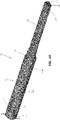
FIG. 4A is an enlarged, perspective view of a distal portion of a waveguide of the ultrasonic surgical instrument ofFIG. 1 ; -
FIG. 4B is a longitudinal, cross-sectional view of a distal body of the waveguide ofFIG. 4A illustrating an internal flow path formed therein; -
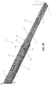
FIG. 5 is a perspective view of the distal portion of the waveguide ofFIG. 4A assembled with inflow and return conduits connected thereto and the fluid flow path sealed closed; -
FIGS. 6A and 6B are perspective and longitudinal, cross-sectional views, respectively, of a distal portion of another waveguide provided in accordance with the present disclosure; -
FIG. 7 is a longitudinal, cross-sectional view of a distal portion of still another waveguide provided in accordance with the present disclosure; -
FIGS. 8A and 8B are perspective and longitudinal, cross-sectional views, respectively, of a distal portion of yet another waveguide provided in accordance with the present disclosure; and -
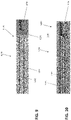
FIGS. 9 and 10 are longitudinal, cross-sectional views of proximal portions of still yet other waveguides provided in accordance with the present disclosure. - Turning to
FIGS. 1 and2 , an ultrasonic surgical instrument provided in accordance with aspects of the present disclosure is generally identified byreference numeral 10.Instrument 10 is a fully cordless instrument that incorporates an on-board cooling system in addition to an on-board power source, e.g., battery, and an ultrasonic generator and transducer. However, it is also contemplated thatinstrument 10 be configured as a corded instrument, e.g., whereininstrument 10 is configured to connect to a remote cooling system by way of one or more fluid lines and to a remote ultrasonic generator (separate from or integrated with the remote cooling system) by way of a cable; or as a partially-corded instrument, e.g., whereininstrument 10 includes an on-board power source and ultrasonic generator and is configured to connect to a remote cooling system by way of one or more fluid lines, or whereininstrument 10 incorporates an on-board cooling system and is configured to connect to a remote ultrasonic generator. Likewise, other style ultrasonic instruments are also contemplated such as, for example, pencil-style instruments, hemostat-style instruments, etc. Thus, although particular aspects and features ofinstrument 10 are detailed below, it is understood that the aspects and features of the present disclosure are equally applicable for use with any other suitable ultrasonic surgical instrument or system, e.g., robotic surgical system 1000 (FIG. 3 ). Other suitable instruments for use in accordance with the present disclosure including remote or on-board cooling systems are described, for example, in Patent Application Pub. No.US 2019/0247073, titled "REMOVABLE FLUID RESERVOIR AND ULTRASONIC SURGICAL INSTRUMENT INCLUDING THE SAME" and filed on February 13, 2018 , and Patent Application Pub. No.US 2017/0281215, titled "DEVICES, SYSTEMS, AND METHODS FOR COOLING A SURGICAL INSTRUMENT" and filed on March 18, 2017 , the entire contents of each of which are hereby incorporated herein by reference. -
Instrument 10 generally includes ahandle assembly 100, anelongated assembly 200 that extends distally fromhandle assembly 100, a transducer and generator assembly ("TAG") 300 configured for releasable engagement withhandle assembly 100, and abattery 400 configured for removable receipt withinhandle assembly 100.Elongated assembly 200 may be integral withhandle assembly 100 or may be releasably engagable withhandle assembly 100. -
Handle assembly 100 includes ahousing 110, acooling system 120, aswitch assembly 140, agenerator dock 150, abattery dock 160, a flex circuit assembly 170 (includingflex circuit portions 182, 184), and aclamp trigger 190. -
Housing 110 ofhandle assembly 100 defines abody portion 112 defining a longitudinal axis and a fixedhandle portion 114 extending frombody portion 112 at an oblique angle relative to the longitudinal axis of body portion 112 (although fixedhandle potion 114 may alternatively extend perpendicularly relative to the longitudinal axis of body portion 112).Body portion 112 ofhousing 110 is configured to receive a proximal portion ofelongated assembly 200 in operable engagement withclamp trigger 190 such that actuation ofclamp trigger 190 manipulatesend effector assembly 280 ofelongated assembly 200. When engaged withbody portion 112 ofhousing 110,elongated assembly 200 is aligned on the longitudinal axis ofbody portion 112.Body portion 112 ofhousing 110 is also configured to supportTAG 300 thereon withtransducer 320 ofTAG 300 mechanically coupled withwaveguide 230 ofelongated assembly 200, e.g., via a threaded connection, latching, or in any other suitable manner, and both aligned on the longitudinal axis ofbody portion 112 ofhousing 110.Generator 340 ofTAG 300 is electrically coupled withgenerator dock 150 ofhousing 110 whenTAG 300 is engaged withbody portion 112 ofhousing 110. Fixedhandle portion 114 ofhousing 110 defines aninternal compartment 116 configured to removably receivebattery 400 therein and a hingeddoor 118 configured to enclosebattery 400 withininternal component 116. -
Cooling system 120 includes one or more fluid pumps 122 and, in some aspects, afluid reservoir 124, althoughfluid reservoir 124 may be omitted in other configurations.Cooling system 120 further includes associatedtubing 126 operably interconnectingfluid pump 122,fluid reservoir 124, and inflow and returnconduits fluid pump 122 and inflow and returnconduits fluid reservoir 124 is omitted) for pumping cooling fluid to and returning cooling fluid fromelongated assembly 200. Inflow and returnconduits elongated assembly 200, ultimately enteringwaveguide 230 thereof to permit circulation of cooling fluid throughblade 282 ofend effector assembly 280 ofelongated assembly 200, as described in greater detail below. - The one or more fluid pumps 122 of
cooling system 120 are supported withinbody portion 112 ofhousing 110. For example, afluid pump 122 may be supported on either or both sides ofbody portion 112 ofhousing 110 at radially-spaced positions relative to the longitudinal axis ofbody portion 112 ofhousing 110. In such a configuration, fluid pumps 122 may define relatively thin, elongate configurations such that sufficient space is defined between thepumps 122 and/or thepump 122 andhousing 110 to permit passage oftransducer 320 ofTAG 300 therebetween (in alignment on the longitudinal axis) while requiring minimal, if any, increase in the overall with dimension ofbody portion 112 ofhousing 110 to accommodate pump(s) 122. - A
connection interface 130 ofcooling system 120 for enabling power and/or control signals to be transmitted to pump(s) 122 is positioned so as not to interfere withTAG 300. Further, aconnector 132, e.g., lead wire, cable, flex circuit, or other suitable connector, extends throughbody portion 112 ofhousing 110 to couple theconnection interface 130 withflex circuit assembly 170 ofhandle assembly 100 to permit communication of power and control signals between pump(s) 122,generator 340,switch assembly 140, and/orbattery 400. More specifically, pump(s) ofcooling system 120 may be controlled via a controller ofgenerator 340,battery 400, or a separate controller ofcooling system 120, e.g., withincontrol box 130. Regardless of the location and/or configuration, the controller is configured to control pump(s) 122 so as to maintain a flow of cooling fluid sufficient to coolblade 282 ofend effector 280, to activate and deactivate cooling in response to manual inputs, and/or to implement automatic cooling (for example, upon deactivation of the supply of energy). The one or more fluid pumps 122 may be piezoelectric microfluidic pumps or other microfluidic pumps such as micro-peristaltic pumps, syringe pumps, etc. Regardless of the particular pump configuration utilized, the one or more fluid pumps 122 may, in aspects, be configured to generate sufficient flow rate of cooling fluid so as to coolwaveguide 230 ofelongated assembly 200 from an initial temperature of about 300°C to about 100°C (or about 120°C) to a cooled temperature of about 70°C to about 0°C (or less than about 60°C) in from about 0.5 seconds to about 2.5 seconds (or in les than about 2 seconds). However, other temperatures and/or cooling times are also contemplated. - Continuing with reference to
FIGS. 1 and2 ,fluid reservoir 124 is disposed withinhousing 110 ofhandle assembly 100. More specifically,fluid reservoir 124 is disposed within fixedhandle portion 114 ofhousing 110 and is positioned betweeninternal compartment 116 of fixedhandle portion 114 andbody portion 112 ofhousing 110.Fluid reservoir 124 may define a cut-out 134 within which at least a portion ofclamp trigger 190 extends upon actuation thereof. As such,fluid reservoir 124 does not interfere with actuation ofclamp trigger 190. It is also contemplated thatfluid reservoir 124 be positioned in other locations, e.g., at a free end of fixedhandle portion 114 such thatbattery 400 is disposed betweenfluid reservoir 124 andbody portion 112. -
Fluid reservoir 124 further includes aport 136 having an input 137a and an output 137b.Tubing 126 ofcooling system 120 is coupled to input 137a and output 137b offluid reservoir 124 to couplefluid reservoir 124 with fluid pump(s) 122 and inflow and returnconduits ends 138a, 138b of the tubes oftubing 126 may extend through input 137a and output 137b and intofluid reservoir 124 such that theends 138a, 138b of the tubes oftubing 126 are disposed at opposite sides, ends, or portions offluid reservoir 124, thereby maximizing the spacing therebetween. This configuration inhibits the hotter, returned cooling fluid from being immediately pumped back out offluid reservoir 124. Further, theends 138a, 138b of the tubes oftubing 126 are positioned withinfluid reservoir 124 relative to one another such that, regardless of the orientation ofhandle assembly 100, any air influid reservoir 124 is inhibited from enteringinflow conduit 128a. -
Switch assembly 140 ofhandle assembly 100 includes anenergy activation button 142 operably positioned to electrically couple to flexcircuit assembly 170.Flex circuit assembly 170 electrically couples switch assembly 140,battery 400, andTAG 300 with one another. Thus, whenenergy activation button 142 is activated in an appropriate manner, power is supplied frombattery 400 toTAG 300.Energy activation button 142 may be configured for dual-mode activation such that, a first activation ofenergy activation button 142drives TAG 300 in a "LOW" power mode, while a second, different activation ofenergy activation button 142drives TAG 300 in a "HIGH" power mode. Other suitable activation configurations are also contemplated. -
Switch assembly 140 ofhandle assembly 100 further includes, in aspects, a pair ofcooling activation buttons 144 operably positioned on either side ofhousing 110.Flex circuit assembly 170 electrically couplesconnection interface 130 ofcooling system 120 withswitch assembly 140,battery 400, andTAG 300. Thus, activation of either or both ofcooling activation buttons 144 initiates cooling. In aspects, multiple activations and/or particular activation patterns of cooling activation button(s) 144 may subsequently terminate cooling, switch between different cooling modes or programs, etc. -
Generator dock 150 is disposed onbody portion 112 ofhousing 110 and is positioned to electrically couple togenerator 340 ofTAG 300 upon engagement ofTAG 300 withhousing 110.Battery dock 160 is disposed withininternal compartment 116 of fixedhandle portion 114 ofhousing 110 and is positioned to electrically couple tobattery 400 upon receipt ofbattery 400 withininternal compartment 116.Docks flex circuit portions connector 132 ofcooling system 120electrically couple TAG 300,switch assembly 140,control box 130 ofcooling system 120, andbattery 400 with one another to enable communication of power and/or control signals therebetween.Flex circuit portion 182, more specifically, interconnectsbattery dock 160 withflex circuit assembly 170. The flexible configuration offlex circuit portion 182 enables routing offlex circuit 182 aboutfluid reservoir 124, which is disposed betweenflex circuit assembly 170 andbattery dock 160.Flex circuit portion 184, on the other hand, electrically couplesflex circuit assembly 170 withgenerator dock 150. - Referring still to
FIGS. 1 and2 ,clamp trigger 190 ofhandle assembly 100 ofinstrument 10 extends frombody portion 112 ofhousing 110 in opposing relation relative to fixedhandle portion 114 ofhousing 110.Clamp trigger 190 is pivotably coupled tobody portion 112 ofhousing 110 and operably associated withelongated assembly 200 such that pivoting ofclamp trigger 190 towards fixedhandle portion 114 ofhousing 110 pivotsjaw 284 ofend effector assembly 280 ofelongated assembly 200 from an open position to a clamping position for clamping tissue betweenjaw 284 andblade 282, which extends distally fromwaveguide 230 ofelongated assembly 200. -
Elongated assembly 200 generally includes a sleeve assembly having anouter sleeve 210 and an inner sleeve (not shown) disposed withinouter sleeve 210,waveguide 230 extending through the inner sleeve (not shown), adrive assembly 250, arotation assembly 270 operably disposed aboutouter sleeve 210, and endeffector assembly 280 disposed at the distal end of the sleeve assembly.End effector assembly 280 includes, as noted above,blade 282 andjaw 284, which is operably coupled toouter sleeve 210 such that translation ofouter sleeve 210 pivotsjaw 284 relative toblade 282 between the open and clamping positions.Drive assembly 250 operably couples a proximal portion ofouter sleeve 210 withclamp trigger 190 such that actuation ofclamp trigger 190 pivotsjaw 284 relative toblade 282 between the open and clamping positions. In the above-detailed configuration, the inner sleeve is a support sleeve and the outer sleeve is a drive sleeve, although the opposite configuration is also contemplated, as are other suitable drive mechanisms for pivotingjaw 284 relative toblade 282. -
Jaw 284 ofend effector assembly 280 includes a more-rigidstructural body 285a and a more-compliant jaw liner 285b.Structural body 285a is pivotably coupled to the inner sleeve ofelongated assembly 200 and operably coupled withouter sleeve 210 ofelongated assembly 200 to enable the above-detailed translation ofouter sleeve 210 to impart pivotal motion ofjaw 284 relative toblade 282 to clamp tissue betweenjaw liner 285b ofjaw 284 andblade 282.Jaw liner 285b is positioned to opposeblade 282 in the clamping position ofjaw 284. -
Waveguide 230 extends through the inner sleeve (not shown), includesblade 282 extending from the distal end thereof and includes a proximal end portion that is configured to operably couple totransducer 320, e.g., via a threaded connection, latching, or in any other suitable manner. Inflow and returnconduits housing 110 at least partially along and/or throughelongated assembly 200 before fluidly coupling with an interior flow path defined withinwaveguide 230 or may fluidly couple withwaveguide 230 withinhousing 110.Waveguide 230, the interior flow path defined withinwaveguide 230, and the connection of inflow and returnconduits waveguide 230 are described in greater detail below. -
TAG 300 andbattery 400 are each removable fromhandle assembly 100 to facilitate disposal ofhandle assembly 100 or to enable sterilization ofhandle assembly 100.TAG 300 may be configured to withstand sterilization such thatTAG 300 may be sterilized for repeated use.Battery 400, on the other hand, is configured to be aseptically transferred and retained withincompartment 116 of fixedhandle portion 114 ofhousing 110 ofhandle assembly 100 such thatbattery 400 may be repeatedly used without requiring sterilization thereof. Alternatively or additionally,battery 400 may be sterilized. In some configurations, TAG 300 (or a portion thereof, e.g.,generator 340 or transducer 320) may be integral withhousing 110. -
TAG 300 includesultrasonic transducer 320 andgenerator 340. A set ofconnectors 362 and corresponding rotational contacts 364 associated withgenerator 340 andultrasonic transducer 320, respectively, enable data and drive signals to be communicated fromgenerator 340 totransducer 320, e.g., the piezoelectric stack oftransducer 320, to drivetransducer 320.Battery 400powers generator 340 to produce a drive signal, e.g., a high voltage AC signal, that is communicated totransducer 320.Transducer 320 converts the signal into mechanical motion that is output alongwaveguide 230 toblade 282 ofend effector assembly 280.Transducer 320 further includes arotation knob 380 disposed at a proximal end thereof to enable rotation oftransducer 320 relative togenerator 340 and handleassembly 100.Rotation knob 380 may also facilitates operable coupling oftransducer 320 withelongated assembly 200. - With reference to
FIG. 3 , a robotic surgical system in accordance with the aspects and features of the present disclosure is shown generally identified byreference numeral 1000. For the purposes herein, roboticsurgical system 1000 is generally described. Aspects and features of roboticsurgical system 1000 not germane to the understanding of the present disclosure are omitted to avoid obscuring the aspects and features of the present disclosure in unnecessary detail. - Robotic
surgical system 1000 generally includes a plurality ofrobot arms control device 1004; and anoperating console 1005 coupled withcontrol device 1004.Operating console 1005 may include adisplay device 1006, which may be set up in particular to display three-dimensional images; andmanual input devices robot arms surgical system 1000 may be configured for use on apatient 1013 lying on a patient table 1012 to be treated in a minimally invasive manner. Roboticsurgical system 1000 may further include adatabase 1014, in particular coupled to controldevice 1004, in which are stored, for example, pre-operative data frompatient 1013 and/or anatomical atlases. - Each of the
robot arms device end effector FIG. 1 ), wherein manual manipulation and actuation features are replaced with robotic inputs. In such configurations, roboticsurgical system 1000 may include or be configured to connect to an ultrasonic generator, a power source, and cooling system. The other surgical tool "ST" may include any other suitable surgical instrument, e.g., an endoscopic camera, other surgical tool, etc.Robot arms device 1004. Control device 1004 (e.g., a computer) may be configured to activate the motors, in particular by means of a computer program, in such a way thatrobot arms devices manual input devices Control device 1004 may also be configured in such a way that it regulates the movement ofrobot arms - Referring to
FIGS. 1 ,2 ,4A ,4B ,waveguide 230, as noted above, includesblade 282 disposed at a distal end thereof.Waveguide 230, more specifically, includes a proximal body 232 (FIGS. 2 and4A ) and a distal body 234 (FIGS. 4A and4B ) that includesblade 282. In aspects,proximal body 232 anddistal body 234 may be integrally formed from a single piece of material or may be separately formed and subsequently attached to one another (permanently or removably).Proximal body 232 anddistal body 234 may, in aspects where proximal anddistal body FIG. 4A ) ofproximal body 232 within a threaded bore 236 (FIGS. 4A and4B ) defined within a proximal end ofdistal body 234. Other methods of attachment are also contemplated, such as various types of welding (e.g., inertial friction welding), brazing, soldering, diffusion bonding, etc.Proximal body 232 and/ordistal body 234 may be formed from aluminum, aluminum alloy, titanium, a titanium alloy, or other suitable similar or different material(s). -
Proximal body 232 ofwaveguide 230 extends fromhousing 110 through at least a portion of the inner support sleeve ofelongated assembly 200 todistal body 234.Proximal body 232 is configured to operable engageultrasonic transducer 320 such that ultrasonic motion produced byultrasonic transducer 320 is transmitted alongproximal body 232 todistal body 234 and, ultimately,blade 282 for treating tissue clamped betweenblade 282 andjaw 284 or positioned adjacent toblade 282.Proximal body 232 may define a generally cylindrical-shaped configuration and may be solid, although hollow or semi-hollow configurations are also contemplated. - With particular reference to
FIGS. 4A and4B ,distal body 234 includes abase 238 andblade 282 extending distally frombase 238.Base 238 andblade 282 may be integrally formed from a single piece of material or may be separately formed and subsequently attached to one another (permanently or removably).Base 238 defines a generally cylindrical-shaped configuration, although other configurations are also contemplated.Blade 282 extends distally frombase 282.Blade 282 may define a substantially linear configuration (as shown), may define a curved configuration, or may define any other suitable configuration, e.g., straight and/or curved surfaces, portions, and/or sections; one or more convex and/or concave surfaces, portions, and/or sections; etc. With respect to curved configurations,blade 282, more specifically, may be curved in any direction relative to jaw 284 (FIG. 1 ), for example, such that the distal tip ofblade 282 is curved towards jaw 284 (FIG. 1 ), away from jaw 284 (FIG. 1 ), or laterally (in either direction) relative to jaw 284 (FIG. 1 ). Further,blade 282 may be formed to include multiple curves in similar directions, multiple curves in different directions within a single plane, and/or multiple curves in different directions in different planes. In addition, although one configuration ofblade 282 is described and illustrated herein, it is contemplated thatblade 282 may additionally or alternatively be formed to include any suitable features, e.g., a tapered configuration, various different cross-sectional configurations along its length, cut-outs, indents, edges, protrusions, straight surfaces, curved surfaces, angled surfaces, wide edges, narrow edges, and/or other features. In aspects,blade 282 defines a pair of relatively narrow generally convex opposed surfaces and a pair of relatively broad generally planar opposed surfaces, although other configurations are also contemplated. One of the narrow surfaces may be positioned to oppose jaw 284 (FIG. 1 ), one of the broad surfaces may be positioned to oppose jaw 284 (FIG. 1 ), orblade 282 and/or jaw 284 (FIG. 1 ) may be relatively rotatable to position a desired surface in opposition to jaw 284 (FIG. 1 ). Atransition region 240 defining a gradual (or more gradual) transition betweenbase 238 andblade 282 may also be provided. -
Distal body 234 may be formed from a solid material into which the various lumens detailed below are formed, although other configurations are also contemplated.Distal body 234, more specifically, includes first and secondlongitudinal lumens base 238 andblade 282.Longitudinal lumens distal apertures blade 282.Longitudinal lumens distal body 234 during manufacture of distal body 234 (e.g., as part of an extrusion process or other suitable formation process) or may be formed subsequent to manufacture of distal body 234 (e.g., via drilling). In either configuration,longitudinal lumens blade 282 proximally throughblade 282 and at least a portion ofbase 238 to closed or open proximal ends. Alternatively, in configurations wheredistal body 234 is removable from proximal body 232 (FIG. 4A ),longitudinal lumens distal body 234 through a proximal end portion of base 238 (or of waveguide 230) to or through the distal face ofblade 282. In aspects, threaded bore 236 ofbase 238 communicates with open proximal ends oflongitudinal lumens plug 233 of proximal body 232 (seeFIG. 4A ) within threadedbore 236 ofbase 238 ofdistal body 234 to attach proximal anddistal bodies longitudinal lumens distal bodies longitudinal lumens longitudinal lumen 242, 244) defined withinproximal body 232 and extending at least partially therethrough to closed or closable proximal ends of the internal lumen(s) ofproximal body 232. In aspects, such internal lumens ofproximal body 232 extend to the proximal end ofproximal body 232 and are sealed closed (themselves or with a seal) via engagement ofproximal body 232 ofwaveguide 230 with transducer 320 (FIG. 2 ), e.g., via the threaded engagement therebetween. - Continuing with reference to
FIGS. 4A and4B , a distaltransverse lumen 246 is defined at least partially throughblade 282 at a distal end portion ofblade 282, e.g., within approximately 15% of a length ofblade 282 from the distal end thereof, in other aspects within approximately 10%, and in still other aspects, within approximately 5%. Distaltransverse lumen 246 may be formed withinblade 282 via drilling, e.g., forming a distaltransverse aperture 247 disposed on one side ofblade 282, or in any other suitable manner. Distaltransverse lumen 246 extends transversely across one of thelongitudinal lumens longitudinal lumen transverse lumen 246 establishes communication betweenlongitudinal lumens blade 282. Distaltransverse lumen 246 may not extend completely throughblade 282, e.g., such that a single distaltransverse aperture 247 is formed, or may extend completely therethrough, e.g., such that a pair of opposed distaltransverse apertures 247 is formed. Distaltransverse lumen 246 may extend in substantially perpendicular orientation relative tolongitudinal lumens -
Base 238 ofdistal body 234 ofwaveguide 230 defines a pair of proximaltransverse lumens transverse lumens proximal body 232 of waveguide 230 (in configuration whereinlongitudinal lumens transverse lumens transverse apertures base 238 into communication withlongitudinal lumens base 238 and extend into communication with respectivelongitudinal lumens Longitudinal lumens transverse lumens transverse lumens base 238 or in any other suitable manner. Proximaltransverse lumens base 238 so as to maintain isolation betweenlongitudinal lumens base 238, or may extend completely throughbase 238 whereby the undesired apertures formed thereby are sealed closed during manufacturing, e.g., according to any of the aspects detailed herein. Whether by initial formation or subsequent sealed closure, proximaltransverse lumens longitudinal lumens longitudinal lumen transverse lumens longitudinal lumens - Referring also to
FIG. 5 , during manufacturing, in order to define a closed fluid circuit from coolingsystem 120, throughwaveguide 230, and back to cooling system 120 (seeFIG. 2 ), inflow and returnconduits longitudinal lumens various apertures waveguide 230 are sealed to inhibit escape of fluid from the closed fluid circuit. Although the fluid circuit from coolingsystem 120 throughwaveguide 230 and back tocooling system 120 is closed,cooling system 120 may itself define an open-loop configuration (e.g., wherein supply fluid and return fluid are separate and return fluid is not re-circulated), a closed-loop configuration (e.g., wherein return fluid is re-circulated as supply fluid), or a semi-closed loop configuration (e.g., wherein some return fluid is re-circulated while other return fluid is not re-circulated). Further still, in other configurations, one ormore apertures waveguide 230 are sealed closed while one or moreother apertures waveguide 230 remain open to enable the direction of fluid fromwaveguide 230 in a particular manner or manners in an open-loop system, e.g., to function as an aspirator and/or suction device. - Inflow and return
conduits transverse apertures transverse aperture 249a, proximaltransverse lumen 248a, and intolongitudinal lumen 242, fromlongitudinal lumen 242 tolongitudinal lumen 244 at the distal end portion ofblade 282 via distaltransverse lumen 246, and to enable the return of return fluid fromlongitudinal lumen 244, through proximaltransverse lumen 248b andtransverse aperture 249b to returnconduit 128b.Inflow conduit 128a and/or returnconduit 128b may, interiorly and/or exteriorly relative towaveguide 230, be oriented substantially perpendicularly relative tolongitudinal lumens transverse lumens longitudinal lumens Angling inflow conduit 128a and/or returnconduit 128b and/or angling either or both proximaltransverse lumens 248a, e.g., in a proximally-angled manner, may facilitate inflow and outflow of fluid to and fromlongitudinal lumens conduits transverse lumens conduits inflow conduit 128a throughlongitudinal lumen 242 and/or proximally throughlongitudinal lumen 244 intoreturn conduit 128b. - Referring still to
FIGS. 4A-5 ,apertures Plugs 260 may be similar or different from one another and may sealinglyclose apertures plugs 260 may be configured, for example, as a rod, e.g., a titanium rod or other rod of similar of different material fromdistal body 234 ofwaveguide 230, that is inserted into the correspondingaperture aperture plugs 260 may be formed from, for example, a high temperature polymer, rubber, or metal and, in these or other aspects, may be welded, thermally interference fit, soldered (wherein the plugs are formed wholly from the solder material or wherein a plug of different material is soldered), brazed, or otherwise secured in position within the correspondingaperture aperture - The
plug 260 configured to sealinglyclose apertures corresponding apertures plugs 260 formed from any suitable material such as any of those detailed herein). Such aplug 260 may define a substantially U-shaped configuration and be inserted from the exterior ofwaveguide 230. Alternatively, such aplug 260 may include an O-ring (itself or together with plug portions extending therefrom) or other seal connector, e.g., a gasket, that is inserted distally throughlumen apertures 243, 245 (and, in some aspects, also aperture 247) closed. - One or more of
plugs 260 may be overmolded from the interior or exterior of thecorresponding aperture aperture plugs 260 may be separately formed and then inserted (from the interior or exterior) and sealed within the correspondingaperture aperture plugs 260 may be configured as a set screw or other threaded element and/or one or more ofapertures more plugs 260 within the corresponding aperture(s) 243, 245, 247, 249a, 249b, from the interior or exterior thereof. - In configurations wherein
longitudinal lumens plugs 260 forapertures outflow conduits plugs 260, be defined within theplugs 260, form theplugs 260, be surrounded by theplugs 260, or be otherwise configured relative to theplugs 260 such that theplugs 260seal apertures outflow conduits waveguide 230 and inflow andoutflow conduits apertures - With general reference to
FIGS. 1-5 , in use, upon activation of cooling,cooling system 120 is configured to pump fluid, using the one or more fluid pumps 122, fromfluid reservoir 124, throughinflow conduit 128a, proximaltransverse lumen 248a, distally throughlongitudinal lumen 242, fromlongitudinal lumen 242 tolongitudinal lumen 244 at the distal end portion ofblade 282 via distaltransverse lumen 246, proximally throughlongitudinal lumen 244, throughtransverse lumen 248b, throughoutflow conduit 128b, and back tofluid reservoir 124. In this manner, cooling fluid is circulated substantially entirely along the length ofblade 282 to facilitatecooling blade 282. The cooling fluid may be saline, water, or other suitable fluid. - Turning to
FIGS. 6A-6B , adistal body 1234 including ablade 1282 of anotherwaveguide 1230 provided in accordance with aspects of the present disclosure is shown. Except as explicitly contradicted below,waveguide 1230 may be configured similarly to and include any of the features of waveguide 230 (FIGS. 1 ,2 ,4A , and4B ). Thus, the following description will focus on differences betweenwaveguide 1230 and waveguide 230 (FIGS. 1 ,2 ,4A , and4B ) while similarities are only summarily described or omitted entirely. -
Distal body 1234 ofwaveguide 1230 includes abase 1238 andblade 1282 extending distally frombase 1238.Distal body 1234 further includes first and secondlongitudinal lumens base 1238 andblade 1282 to open distal ends. Acap 1250 defining aconnector lumen 1252 is welded, soldered, or otherwise secured to the distal end ofblade 1282 to thereby define a distal tip ofblade 1282.Cap 1250 may be formed from the same material asblade 1282 or a different material. Upon securingcap 1250 to the distal end ofblade 1282,connector lumen 1252 establishes communication between the open distal ends oflongitudinal lumens distal body 1234. Thus, cooling fluid can be pumped distally throughdistal body 1234 via one oflongitudinal lumens distal body 1234 viaconnector lumen 1252 and the otherlongitudinal lumen distal body 1234 ofwaveguide 1230. With respect todistal body 1234, a transverse lumen need not be provided towards distal ends oflongitudinal lumens - With reference to
FIG. 7 , adistal body 2234 including ablade 2282 of anotherwaveguide 2230 provided in accordance with aspects of the present disclosure is shown.Distal body 2234 is similar to and may include any of the features of distal body 1234 (FIGS. 6A and 6B ) except as explicitly contradicted below. -
Distal body 2234 ofwaveguide 2230 includes abase 2238 andblade 2282 extending distally frombase 2238.Distal body 2234 further includes first and secondlongitudinal lumens base 2238 andblade 2282.Longitudinal lumens transverse lumen 2246 disposed at the distal end ofblade 2282 and in communication with an open distal end thereof. Thus,lumens blade 2282. - A
cap 2250 including abase 2252 and ahead 2254 is welded, soldered, or otherwise secured to the distal end ofblade 2282 to thereby define a distal tip ofblade 2282 withbase 2252 extending at least partially into the open distal end ofblade 2282 andhead 2254 abutting the distal face(s) ofblade 2282. Upon securingcap 2250 to the distal end ofblade 2282 in this manner, the open distal end ofblade 2282 is sealed closed while still maintaining a fluid flow path betweenlongitudinal lumens transverse lumen 2246. Thus, cooling fluid can be pumped distally throughdistal body 2234 via one oflongitudinal lumens distal body 2234 viatransverse lumen 2246 and the otherlongitudinal lumen distal body 2234 ofwaveguide 2230.Base 2252 ofcap 2250 facilitates proper alignment and orientation ofcap 2250 relative toblade 2282 upon welding or otherwise securingcap 2250 toblade 2282. - Referring to
FIGS. 8A and 8B , adistal body 3234 including ablade 3282 of anotherwaveguide 3230 provided in accordance with aspects of the present disclosure is shown.Distal body 3234 is similar to and may include any of the features of distal body 1234 (FIGS. 6A and 6B ) except as explicitly contradicted below. - Rather than providing a
cap 1250 as detailed above with respect to distal body 1234 (seeFIGS. 6A and 6B ),distal body 3234 includes a bent pipe 3250 (curved, angled, and/or otherwise bent) defining alumen 3252 therethrough secured, e.g., welded, soldered, or otherwise secured, to the distal end ofblade 3282 such thatlumen 3252 establishes communication between the open distal ends oflongitudinal lumens distal body 3234. Thus, cooling fluid can be pumped distally throughdistal body 3234 via one oflongitudinal lumens distal body 3234 vialumen 3252 and the otherlongitudinal lumen distal body 3234 ofwaveguide 3230. - With general reference to
FIGS. 6A-8B , in aspects,cap 1250,cap 2250, and/orpipe 3250 may define features to facilitate tissue treatment. For example,cap 1250,cap 2250, and/orpipe 3250 may define angled, rounded, curved, and/or other suitable configurations to facilitate, for example, performing otomies, blunt dissection, and/or other surgical tasks with or without ultrasonic energy. - Turning to
FIGS. 9 and 10 , proximal end portions of thedistal bodies other waveguides waveguides FIGS. 1 ,2 ,4A , and4B ), any of the other waveguides detailed herein, and/or any other suitable waveguide. Thus, the following description will focus on differences betweenwaveguides FIGS. 1 ,2 ,4A , and4B ), while similarities are only summarily described or omitted entirely. - Referring to
FIG. 9 ,distal body 4234 ofwaveguide 4230 defineslongitudinal lumens Longitudinal lumens distal body 4234.Distal body 4234 ofwaveguide 4230 further includes aconnector body 4250 secured, e.g., welded, soldered, or otherwise secured, to the proximal end ofdistal body 4234.Connector body 4250 may be formed from the same or a different material asdistal body 4234 and, upon securingconnector body 4250 to the proximal end ofdistal body 4234, seals closed the proximal ends oflongitudinal lumens Connector body 4250 may further include aproximal bore 4236 to enable threaded or other suitable engagement of the proximal body (not shown, see proximal body 232 (FIG. 4A )) ofwaveguide 4230 withinproximal bore 4236 to thereby secure the proximal body anddistal body 4234 with one another (viaconnector body 4250 therebetween) to enable ultrasonic energy transmission therealong. - With reference to
FIG. 10 ,distal body 5234 ofwaveguide 5230 defineslongitudinal lumens proximal bore 5236 defined therein at the proximal end thereof. The proximal ends oflongitudinal lumens proximal bore 5236. Aplug 5250 is secured withinproximal bore 5236 at the open proximal ends oflongitudinal lumens longitudinal lumens Plug 5250 may be formed from any suitable material similar or different from that ofwaveguide 5230 and may be welded, soldered, adhered, molded, compression-fit (such as whereplug 5250 is formed from a resilient material), threaded, or otherwise secured withinproximal bore 5236.Plug 5250 occupies only a portion ofproximal bore 5236 to enable threaded or other suitable engagement of the proximal body (not shown, see proximal body 232 (FIG. 4A )) ofwaveguide 5230 withinproximal bore 5236 to thereby secure the proximal body anddistal body 5234 with one another to enable ultrasonic energy transmission therealong. - While several aspects and features of the disclosure are detailed above and shown in the drawings, it is not intended that the disclosure be limited thereto, as it is intended that the disclosure be as broad in scope as the art will allow and that the specification be read likewise. Therefore, the above description and accompanying drawings should not be construed as limiting, but merely as exemplifications of particular configurations. Those skilled in the art will envision other modifications within the scope and spirit of the claims appended hereto.
- The invention may be described by reference to the following numbered paragraphs:-
- 1. An ultrasonic surgical system, comprising:
- an ultrasonic waveguide body defining first and second longitudinal lumens extending through at least a portion of a length of the ultrasonic waveguide body;
- a distal transverse lumen defined within the ultrasonic waveguide body transversely through at least a portion of the ultrasonic waveguide body to intersect and interconnect the first and second longitudinal lumens;
- a first proximal transverse lumen extending from a first proximal transverse aperture within the ultrasonic waveguide body transversely through a portion of the ultrasonic waveguide body to intersect the first longitudinal lumen;
- a second proximal transverse lumen extending from a second proximal transverse aperture within the ultrasonic waveguide body transversely through a portion of the ultrasonic waveguide body to intersect the second longitudinal lumen; and
- inflow and outflow conduits fluidly coupled with the first and second proximal transverse apertures, respectively, to enable the inflow of fluid into the first longitudinal lumen and the outflow of fluid from the second longitudinal lumen, respectively.
- 2. The ultrasonic surgical system according to
paragraph 1, wherein the first and second longitudinal lumens extend proximally from first and second distal face apertures defined within a distal face of the ultrasonic waveguide body, and wherein at least one distal face aperture plug closes the first and second distal face apertures to inhibit escape of fluid therethrough. - 3. The ultrasonic surgical system according to
paragraph 1, wherein the distal transverse lumen extends from a distal transverse aperture and wherein a distal transverse aperture plug closes the distal transverse aperture to inhibit escape of fluid therethrough. - 4. The ultrasonic surgical system according to
paragraph 1, wherein first and second proximal transverse aperture plugs form a seal between the inflow and outflow conduits and the first and second proximal transverse apertures, respectively. - 5. The ultrasonic surgical system according to
paragraph 1, further comprising:
a proximal waveguide body adapted to connect to an ultrasonic transducer, wherein the ultrasonic waveguide body is a distal waveguide body including a blade, the distal waveguide body extending distally from the proximal waveguide body. - 6. The ultrasonic surgical system according to paragraph 5, wherein the distal waveguide body is releasably engagable with the proximal waveguide body.
- 7. The ultrasonic surgical system according to paragraph 6, wherein engagement of the proximal and distal waveguide bodies closes proximal ends of the first and second longitudinal lumens.
- 8. The ultrasonic surgical instrument according to
paragraph 1, wherein the waveguide body includes a base and a blade extending distally from the base, the blade defining opposed narrow surfaces and opposed broad surfaces. - 9. The ultrasonic surgical instrument according to paragraph 8, wherein at least a portion of the distal transverse lumen is disposed within 10% of a length of the blade from a distal end of the blade.
- 10. The ultrasonic surgical system according to
paragraph 1, wherein the distal transverse lumen is at least partially formed via a distal cap defining a distal tip of the distal waveguide body. - 11. The ultrasonic surgical system according to
paragraph 1, further comprising:- a cooling system configured to pump cooling fluid through the inflow conduit into the first longitudinal lumen and/or pump cooling fluid through the second longitudinal lumen into the outflow conduit;
- a housing at least partially supporting the cooling system; and
- an elongated assembly extending distally from the housing, the elongated assembly including the ultrasonic waveguide body.
- 12. The ultrasonic surgical system according to paragraph 11, wherein the housing further supports an ultrasonic transducer configured to produce ultrasonic energy for transmission along the ultrasonic waveguide body.
- 13. The ultrasonic surgical system according to paragraph 12, wherein the housing further supports an ultrasonic generator configured to produce an ultrasonic drive signal for driving the ultrasonic transducer, and a battery configured to power the ultrasonic generator.
- 14. A method of manufacturing an ultrasonic surgical system, comprising:
- forming first and second longitudinal lumens through at least a portion of a length of an ultrasonic waveguide body;
- forming a distal transverse lumen transversely through at least a portion of the ultrasonic waveguide body to intersect and interconnect the first and second longitudinal lumens;
- forming first and second proximal transverse lumens transversely through a portion of the ultrasonic waveguide body to intersect the first and second longitudinal lumens, respectively;
- plugging apertures formed from the formation of the first and second longitudinal lumens;
- plugging an aperture formed from the formation of the distal transverse lumen.
- 15. The method according to paragraph 14, further comprising fluidly connecting an inflow conduit with the first proximal transverse aperture.
- 16. The method according to paragraph 14, further comprising fluidly connecting an outflow conduit with the second proximal transverse aperture.
- 17. The method according to paragraph 14, further comprising attaching the ultrasonic waveguide body, as a distal waveguide body, to a proximal waveguide body.
- 18. The method according to paragraph 17, wherein the attaching closes proximal ends of the first and second longitudinal lumens.
- 19. The method according to paragraph 14, further comprising:
coupling the first and second proximal transverse lumens with inflow and outflow conduits, respectively, associated with a cooling system including at least one pump and a fluid reservoir. - 20. The method according to paragraph 14, wherein forming the distal transverse lumen includes securing a cap to a distal end of the ultrasonic waveguide body to define a distal tip thereof.
Claims (15)
- An ultrasonic surgical system, comprising:an ultrasonic waveguide body defining first and second longitudinal lumens extending through at least a portion of a length of the ultrasonic waveguide body;a distal transverse lumen defined within the ultrasonic waveguide body transversely through at least a portion of the ultrasonic waveguide body to intersect and interconnect the first and second longitudinal lumens;a first proximal transverse lumen extending from a first proximal transverse aperture within the ultrasonic waveguide body transversely through a portion of the ultrasonic waveguide body to intersect the first longitudinal lumen;a second proximal transverse lumen extending from a second proximal transverse aperture within the ultrasonic waveguide body transversely through a portion of the ultrasonic waveguide body to intersect the second longitudinal lumen; andinflow and outflow conduits fluidly coupled with the first and second proximal transverse apertures, respectively, to enable the inflow of fluid into the first longitudinal lumen and the outflow of fluid from the second longitudinal lumen, respectively.
- The ultrasonic surgical system according to claim 1, wherein the first and second longitudinal lumens extend proximally from first and second distal face apertures defined within a distal face of the ultrasonic waveguide body, and wherein at least one distal face aperture plug closes the first and second distal face apertures to inhibit escape of fluid therethrough.
- The ultrasonic surgical system according to claim 1 or 2, wherein the distal transverse lumen extends from a distal transverse aperture and wherein a distal transverse aperture plug closes the distal transverse aperture to inhibit escape of fluid therethrough.
- The ultrasonic surgical system according to claim 1, 2 or 3 wherein first and second proximal transverse aperture plugs form a seal between the inflow and outflow conduits and the first and second proximal transverse apertures, respectively.
- The ultrasonic surgical system according to any preceding claim, further comprising:
a proximal waveguide body adapted to connect to an ultrasonic transducer, wherein the ultrasonic waveguide body is a distal waveguide body including a blade, the distal waveguide body extending distally from the proximal waveguide body preferably wherein the distal waveguide body is releasably engageable with the proximal waveguide body, yet further preferably wherein engagement of the proximal and distal waveguide bodies closes proximal ends of the first and second longitudinal lumens. - The ultrasonic surgical instrument according to any preceding claim, wherein the waveguide body includes a base and a blade extending distally from the base, the blade defining opposed narrow surfaces and opposed broad surfaces, preferably wherein at least a portion of the distal transverse lumen is disposed within 10% of a length of the blade from a distal end of the blade.
- The ultrasonic surgical system according to any preceding claim, wherein the distal transverse lumen is at least partially formed via a distal cap defining a distal tip of the distal waveguide body.
- The ultrasonic surgical system according to any preceding claim, further comprising:a cooling system configured to pump cooling fluid through the inflow conduit into the first longitudinal lumen and/or pump cooling fluid through the second longitudinal lumen into the outflow conduit;a housing at least partially supporting the cooling system; andan elongated assembly extending distally from the housing, the elongated assembly including the ultrasonic waveguide body preferably wherein the housing further supports an ultrasonic transducer configured to produce ultrasonic energy for transmission along the ultrasonic waveguide body.
- The ultrasonic surgical system according to claim 8, wherein the housing further supports an ultrasonic generator configured to produce an ultrasonic drive signal for driving the ultrasonic transducer, and a battery configured to power the ultrasonic generator.
- A method of manufacturing an ultrasonic surgical system, comprising:forming first and second longitudinal lumens through at least a portion of a length of an ultrasonic waveguide body;forming a distal transverse lumen transversely through at least a portion of the ultrasonic waveguide body to intersect and interconnect the first and second longitudinal lumens;forming first and second proximal transverse lumens transversely through a portion of the ultrasonic waveguide body to intersect the first and second longitudinal lumens, respectively;plugging apertures formed from the formation of the first and second longitudinal lumens;plugging an aperture formed from the formation of the distal transverse lumen.
- The method according to claim 10, further comprising fluidly connecting an inflow conduit with the first proximal transverse aperture.
- The method according to claim 10 or 11, further comprising fluidly connecting an outflow conduit with the second proximal transverse aperture.
- The method according to 10, 11 or 12, further comprising attaching the ultrasonic waveguide body, as a distal waveguide body, to a proximal waveguide body preferably wherein the attaching closes proximal ends of the first and second longitudinal lumens.
- The method according to any one of claims 10 to 13, further comprising:
coupling the first and second proximal transverse lumens with inflow and outflow conduits, respectively, associated with a cooling system including at least one pump and a fluid reservoir. - The method according to any one of claims 10 to 14, wherein forming the distal transverse lumen includes securing a cap to a distal end of the ultrasonic waveguide body to define a distal tip thereof.
Applications Claiming Priority (2)
| Application Number | Priority Date | Filing Date | Title |
|---|---|---|---|
| US202163134268P | 2021-01-06 | 2021-01-06 | |
| US17/541,951 US12414793B2 (en) | 2021-01-06 | 2021-12-03 | Devices, systems, and methods of manufacturing fluid-cooled ultrasonic surgical instruments |
Publications (2)
| Publication Number | Publication Date |
|---|---|
| EP4026503A1 true EP4026503A1 (en) | 2022-07-13 |
| EP4026503B1 EP4026503B1 (en) | 2024-05-22 |
Family
ID=79270092
Family Applications (1)
| Application Number | Title | Priority Date | Filing Date |
|---|---|---|---|
| EP22150452.5A Active EP4026503B1 (en) | 2021-01-06 | 2022-01-06 | Devices, systems and methods of manufacturing fluid-cooled ultrasonic surgical instruments |
Country Status (3)
| Country | Link |
|---|---|
| US (1) | US12414793B2 (en) |
| EP (1) | EP4026503B1 (en) |
| CN (1) | CN114711902B (en) |
Families Citing this family (1)
| Publication number | Priority date | Publication date | Assignee | Title |
|---|---|---|---|---|
| US5885495A (en) | 1996-12-19 | 1999-03-23 | Ibar; Jean-Pierre | Viscosity control for molten plastics prior to molding |
Citations (3)
| Publication number | Priority date | Publication date | Assignee | Title |
|---|---|---|---|---|
| EP3061415A1 (en) * | 2015-02-24 | 2016-08-31 | Covidien LP | Ultrasonic surgical instrument with cooling system |
| US20170281215A1 (en) | 2016-03-29 | 2017-10-05 | Covidien Lp | Devices, systems, and methods for cooling a surgical instrument |
| US20190247073A1 (en) | 2018-02-13 | 2019-08-15 | Covidien Lp | Removable fluid reservoir and ultrasonic surgical instrument including the same |
Family Cites Families (108)
| Publication number | Priority date | Publication date | Assignee | Title |
|---|---|---|---|---|
| NL145136C (en) | 1967-07-25 | 1900-01-01 | ||
| US4016882A (en) | 1975-03-05 | 1977-04-12 | Cavitron Corporation | Neurosonic aspirator and method |
| US4223676A (en) | 1977-12-19 | 1980-09-23 | Cavitron Corporation | Ultrasonic aspirator |
| EP0139753B1 (en) | 1983-04-04 | 1988-11-09 | Sumitomo Bakelite Company Limited | Ultrasonic oscillator |
| US4660573A (en) | 1985-05-08 | 1987-04-28 | Fibra-Sonics, Inc. | Ultrasonic lithotriptor probe |
| JPS6266848A (en) | 1985-09-20 | 1987-03-26 | 住友ベークライト株式会社 | Surgical operation appliance |
| SU1417868A1 (en) | 1985-11-20 | 1988-08-23 | Томский государственный медицинский институт | Cryoultrasonic scalpel |
| US4681561A (en) | 1986-01-24 | 1987-07-21 | Coopervision, Inc. | Ultrasonic decoupling sleeve |
| SU1563684A1 (en) | 1986-05-26 | 1990-05-15 | Томский государственный медицинский институт | Cryosurgical scalpel |
| JPS63122923A (en) | 1986-11-13 | 1988-05-26 | Agency Of Ind Science & Technol | Ultrasonic thermometric apparatus |
| US5076276A (en) | 1989-11-01 | 1991-12-31 | Olympus Optical Co., Ltd. | Ultrasound type treatment apparatus |
| US5163433A (en) | 1989-11-01 | 1992-11-17 | Olympus Optical Co., Ltd. | Ultrasound type treatment apparatus |
| US5391144A (en) | 1990-02-02 | 1995-02-21 | Olympus Optical Co., Ltd. | Ultrasonic treatment apparatus |
| US5211625A (en) | 1990-03-20 | 1993-05-18 | Olympus Optical Co., Ltd. | Ultrasonic treatment apparatus |
| AU630294B2 (en) | 1990-05-11 | 1992-10-22 | Sumitomo Bakelite Company Limited | Surgical ultrasonic horn |
| WO1991017716A1 (en) | 1990-05-17 | 1991-11-28 | Sumitomo Bakelite Company Limited | Surgical instrument |
| US5358505A (en) | 1991-05-29 | 1994-10-25 | Sonokinetics, Inc. | Tapered tip ultrasonic aspiration method |
| US5221282A (en) | 1991-05-29 | 1993-06-22 | Sonokinetics Group | Tapered tip ultrasonic aspirator |
| US6770071B2 (en) | 1995-06-07 | 2004-08-03 | Arthrocare Corporation | Bladed electrosurgical probe |
| US5261922A (en) | 1992-02-20 | 1993-11-16 | Hood Larry L | Improved ultrasonic knife |
| US5797931A (en) | 1992-06-04 | 1998-08-25 | Olympus Optical Co., Ltd. | Tissue-fixing surgical instrument, tissue-fixing device, and method of fixing tissues |
| AU5456494A (en) | 1992-11-13 | 1994-06-08 | American Cardiac Ablation Co., Inc. | Fluid cooled electrosurgical probe |
| US5462522A (en) | 1993-04-19 | 1995-10-31 | Olympus Optical Co., Ltd. | Ultrasonic therapeutic apparatus |
| US5419761A (en) | 1993-08-03 | 1995-05-30 | Misonix, Inc. | Liposuction apparatus and associated method |
| US5560362A (en) | 1994-06-13 | 1996-10-01 | Acuson Corporation | Active thermal control of ultrasound transducers |
| US6380264B1 (en) | 1994-06-23 | 2002-04-30 | Kimberly-Clark Corporation | Apparatus and method for emulsifying a pressurized multi-component liquid |
| US5496342A (en) | 1994-10-19 | 1996-03-05 | Urich; Alex | Ultrasonic device with temperature sensing sleeve |
| US5486162A (en) | 1995-01-11 | 1996-01-23 | Fibrasonics, Inc. | Bubble control device for an ultrasonic surgical probe |
| US6409722B1 (en) | 1998-07-07 | 2002-06-25 | Medtronic, Inc. | Apparatus and method for creating, maintaining, and controlling a virtual electrode used for the ablation of tissue |
| US5897553A (en) | 1995-11-02 | 1999-04-27 | Medtronic, Inc. | Ball point fluid-assisted electrocautery device |
| US6544264B2 (en) | 1995-03-10 | 2003-04-08 | Seedling Enterprises, Llc | Electrosurgery with cooled electrodes |
| US5647871A (en) | 1995-03-10 | 1997-07-15 | Microsurge, Inc. | Electrosurgery with cooled electrodes |
| US6053424A (en) | 1995-12-21 | 2000-04-25 | Kimberly-Clark Worldwide, Inc. | Apparatus and method for ultrasonically producing a spray of liquid |
| US5624393A (en) | 1996-01-03 | 1997-04-29 | Diamond; Eric L. | Irrigation system for surgical instruments |
| US5906628A (en) | 1996-06-26 | 1999-05-25 | Olympus Optical Co., Ltd. | Ultrasonic treatment instrument |
| US6719755B2 (en) | 1996-10-22 | 2004-04-13 | Epicor Medical, Inc. | Methods and devices for ablation |
| US5830192A (en) | 1996-12-09 | 1998-11-03 | Staar Surgical Company, Inc. | Irrigation sleeve for phacoemulsification apparatus |
| US5879363A (en) | 1997-03-18 | 1999-03-09 | Circuit Tree Medical, Inc. | Disposable surgical ultrasonic transducer |
| US6383183B1 (en) | 1998-04-09 | 2002-05-07 | Olympus Optical Co., Ltd. | High frequency treatment apparatus |
| US6120519A (en) | 1998-12-02 | 2000-09-19 | Weber; Paul J. | Advanced fulcrum liposuction device |
| US6073492A (en) | 1998-12-17 | 2000-06-13 | Kay-Ray Sensall, Inc. | Ultrasonic sensor for very high temperatures and pressures |
| US6569158B1 (en) | 1999-01-25 | 2003-05-27 | Cryocath Technologies, Inc. | Leak detection system |
| US6855123B2 (en) * | 2002-08-02 | 2005-02-15 | Flow Cardia, Inc. | Therapeutic ultrasound system |
| US6454781B1 (en) | 1999-05-26 | 2002-09-24 | Ethicon Endo-Surgery, Inc. | Feedback control in an ultrasonic surgical instrument for improved tissue effects |
| CA2376075A1 (en) | 1999-06-04 | 2000-12-14 | Dentsply International Inc. | Microendodontics ultrasonic surgical dental tool having water port and method of making same |
| US6551337B1 (en) | 1999-10-05 | 2003-04-22 | Omnisonics Medical Technologies, Inc. | Ultrasonic medical device operating in a transverse mode |
| US6379371B1 (en) | 1999-11-15 | 2002-04-30 | Misonix, Incorporated | Ultrasonic cutting blade with cooling |
| US6443969B1 (en) | 2000-08-15 | 2002-09-03 | Misonix, Inc. | Ultrasonic cutting blade with cooling |
| US6633234B2 (en) | 2000-10-20 | 2003-10-14 | Ethicon Endo-Surgery, Inc. | Method for detecting blade breakage using rate and/or impedance information |
| US7273483B2 (en) | 2000-10-20 | 2007-09-25 | Ethicon Endo-Surgery, Inc. | Apparatus and method for alerting generator functions in an ultrasonic surgical system |
| US7530986B2 (en) | 2001-01-08 | 2009-05-12 | Ethicon Endo-Surgery, Inc. | Laminated ultrasonic end effector |
| US8348880B2 (en) | 2001-04-04 | 2013-01-08 | Ethicon Endo-Surgery, Inc. | Ultrasonic surgical instrument incorporating fluid management |
| US6939350B2 (en) | 2001-10-22 | 2005-09-06 | Boston Scientific Scimed, Inc. | Apparatus for supporting diagnostic and therapeutic elements in contact with tissue including electrode cooling device |
| US20030181904A1 (en) | 2002-01-23 | 2003-09-25 | Levine Andy H. | Electrosurgical cutting, coagulating and suction instrument |
| US20030204199A1 (en) | 2002-04-30 | 2003-10-30 | Novak Theodore A. D. | Device and method for ultrasonic tissue excision with tissue selectivity |
| US20040087972A1 (en) | 2002-09-16 | 2004-05-06 | Mulholland Robert Stephen | Skin abrading apparatus |
| US6923421B2 (en) | 2002-09-23 | 2005-08-02 | Red Valve Co., Inc. | Flexible half sleeve style pinch valve |
| US20050209578A1 (en) | 2004-01-29 | 2005-09-22 | Christian Evans Edward A | Ultrasonic catheter with segmented fluid delivery |
| JP4343778B2 (en) | 2004-06-16 | 2009-10-14 | オリンパス株式会社 | Ultrasonic surgical device |
| US20060195106A1 (en) | 2005-02-02 | 2006-08-31 | Jones Bryan S | Ultrasonic cutting device |
| JP4481922B2 (en) | 2005-05-13 | 2010-06-16 | オリンパスメディカルシステムズ株式会社 | Medical treatment tool |
| US7572268B2 (en) | 2005-10-13 | 2009-08-11 | Bacoustics, Llc | Apparatus and methods for the selective removal of tissue using combinations of ultrasonic energy and cryogenic energy |
| US7842032B2 (en) | 2005-10-13 | 2010-11-30 | Bacoustics, Llc | Apparatus and methods for the selective removal of tissue |
| US7871392B2 (en) | 2006-01-12 | 2011-01-18 | Integra Lifesciences (Ireland) Ltd. | Endoscopic ultrasonic surgical aspirator for use in fluid filled cavities |
| US20080281200A1 (en) | 2007-05-10 | 2008-11-13 | Misonix, Incorporated | Elevated coupling liquid temperature during HIFU treatment method and hardware |
| US9271751B2 (en) | 2007-05-29 | 2016-03-01 | Ethicon Endo-Surgery, Llc | Ultrasonic surgical system |
| US9044261B2 (en) | 2007-07-31 | 2015-06-02 | Ethicon Endo-Surgery, Inc. | Temperature controlled ultrasonic surgical instruments |
| US8641609B2 (en) | 2007-10-23 | 2014-02-04 | Zimmer Spine, Inc. | Surgical access system and method of using the same |
| US20090306550A1 (en) | 2008-06-04 | 2009-12-10 | Eilaz Babaev | Ultrasonic Endometrial Cryoablation Method |
| US10179068B2 (en) | 2008-06-26 | 2019-01-15 | Surgical Design Corporation | Surgical hand piece with rotatable dual lumen work tip |
| US8641658B1 (en) | 2008-06-26 | 2014-02-04 | Surgical Design Corporation | Surgical hand piece with dual lumen work tip |
| US9089360B2 (en) | 2008-08-06 | 2015-07-28 | Ethicon Endo-Surgery, Inc. | Devices and techniques for cutting and coagulating tissue |
| US20100274236A1 (en) | 2009-04-23 | 2010-10-28 | Krimsky William S | Apparatuses and methods for applying a cryogenic effect to tissue and cutting tissue |
| US20100298743A1 (en) | 2009-05-20 | 2010-11-25 | Ethicon Endo-Surgery, Inc. | Thermally-activated coupling arrangements and methods for attaching tools to ultrasonic surgical instruments |
| US9737735B2 (en) | 2009-08-14 | 2017-08-22 | Ethicon Llc | Ultrasonic surgical apparatus with silicon waveguide |
| JP2012100736A (en) | 2010-11-08 | 2012-05-31 | Olympus Corp | Ultrasonic treatment device |
| WO2012124653A1 (en) | 2011-03-17 | 2012-09-20 | オリンパスメディカルシステムズ株式会社 | Medical pump and medical treatment device |
| US9113943B2 (en) | 2011-03-30 | 2015-08-25 | Covidien Lp | Ultrasonic surgical instruments |
| CN103796703B (en) | 2011-05-27 | 2016-05-25 | 克纳维医药公司 | Medical probe with fluid swivel |
| US8974478B2 (en) | 2011-09-20 | 2015-03-10 | Covidien Lp | Ultrasonic surgical system having a fluid cooled blade and related cooling methods therefor |
| US8945112B2 (en) | 2011-10-03 | 2015-02-03 | Covidien Lp | External cooling devices and systems for surgical instruments |
| US20130090576A1 (en) | 2011-10-10 | 2013-04-11 | Foster B. Stulen | Surgical instrument with ultrasonic waveguide defining a fluid lumen |
| US9113930B2 (en) | 2012-01-05 | 2015-08-25 | Covidien Lp | Ablation systems, probes, and methods for reducing radiation from an ablation probe into the environment |
| US20140135804A1 (en) | 2012-11-15 | 2014-05-15 | Ethicon Endo-Surgery, Inc. | Ultrasonic and electrosurgical devices |
| US9276300B2 (en) | 2012-11-27 | 2016-03-01 | Covidien Lp | Surgical instruments |
| US9101344B2 (en) | 2013-03-15 | 2015-08-11 | Covidien Lp | Recirculating cooling system for energy delivery device |
| JP6192367B2 (en) | 2013-06-04 | 2017-09-06 | オリンパス株式会社 | Ultrasonic treatment device |
| US9320528B2 (en) | 2013-06-26 | 2016-04-26 | Misonix, Incorporated | Ultrasonic cutting blade with cooling liquid conduction |
| US9211137B2 (en) | 2013-06-28 | 2015-12-15 | Misonix, Incorporated | Ultrasonic cutting blade with cooling liquid conduction |
| US9387005B2 (en) | 2013-06-28 | 2016-07-12 | Misonix, Incorporated | Ultrasonic cutting blade with cooling liquid conduction |
| EP3031417B8 (en) | 2013-08-07 | 2022-05-25 | Olympus Corporation | Ultrasonic probe and ultrasonic treatment apparatus |
| US9622767B2 (en) | 2013-09-11 | 2017-04-18 | Covidien Lp | Ultrasonic surgical instrument with cooling system |
| US9655641B2 (en) | 2013-09-11 | 2017-05-23 | Covidien Lp | Ultrasonic surgical instrument with cooling system |
| US9764166B2 (en) | 2013-09-11 | 2017-09-19 | Covidien Lp | Ultrasonic surgical instrument with cooling system |
| US20150088137A1 (en) | 2013-09-26 | 2015-03-26 | Misonix Incorporated | Ultrasonic surgical instrument with dual end effector |
| EP3073939B1 (en) | 2013-11-26 | 2024-04-17 | Ethicon LLC | Ultrasonic surgical instrument with staged clamping |
| WO2015088016A1 (en) | 2013-12-13 | 2015-06-18 | オリンパス株式会社 | Inspection probe, vibration state inspection system, and vibration state inspection method |
| US9895160B2 (en) | 2014-04-16 | 2018-02-20 | Gyrus Acmi Inc. | Surgical operating apparatus with temperature control |
| US9554809B2 (en) | 2014-09-30 | 2017-01-31 | Robert K. Lark | Ultrasonic blade with static casing |
| US10842587B2 (en) | 2014-11-12 | 2020-11-24 | Misonix, Incorporated | Method for minimally invasive surgery using therapeutic ultrasound to treat spine and orthopedic diseases, injuries and deformities |
| US10206705B2 (en) | 2014-11-25 | 2019-02-19 | Ethicon Llc | Features for communication of fluid through shaft assembly of ultrasonic surgical instrument |
| US10004529B2 (en) | 2014-11-25 | 2018-06-26 | Ethicon Llc | Features to drive fluid toward an ultrasonic blade of a surgical instrument |
| US10433863B2 (en) | 2014-11-25 | 2019-10-08 | Ethicon Llc | Ultrasonic surgical instrument with blade cooling through retraction |
| US10342566B2 (en) | 2016-03-29 | 2019-07-09 | Covidien Lp | Devices, systems, and methods for cooling a surgical instrument |
| US20170325886A1 (en) | 2016-05-16 | 2017-11-16 | Omniguide, Inc. | Multi-function handpieces for energy-based surgery |
| US10368897B2 (en) | 2017-02-09 | 2019-08-06 | Covidien Lp | Ultrasonic surgical instrument |
| US12496115B2 (en) | 2018-03-02 | 2025-12-16 | The General Hospital Corporation | Devices, systems, and methods for cryogenic biopsy sampling |
| WO2023139529A1 (en) * | 2022-01-21 | 2023-07-27 | Covidien Lp | Fluid-cooled ultrasonic surgical instruments |
-
2021
- 2021-12-03 US US17/541,951 patent/US12414793B2/en active Active
-
2022
- 2022-01-06 CN CN202210007534.1A patent/CN114711902B/en active Active
- 2022-01-06 EP EP22150452.5A patent/EP4026503B1/en active Active
Patent Citations (3)
| Publication number | Priority date | Publication date | Assignee | Title |
|---|---|---|---|---|
| EP3061415A1 (en) * | 2015-02-24 | 2016-08-31 | Covidien LP | Ultrasonic surgical instrument with cooling system |
| US20170281215A1 (en) | 2016-03-29 | 2017-10-05 | Covidien Lp | Devices, systems, and methods for cooling a surgical instrument |
| US20190247073A1 (en) | 2018-02-13 | 2019-08-15 | Covidien Lp | Removable fluid reservoir and ultrasonic surgical instrument including the same |
Also Published As
| Publication number | Publication date |
|---|---|
| US12414793B2 (en) | 2025-09-16 |
| CN114711902A (en) | 2022-07-08 |
| EP4026503B1 (en) | 2024-05-22 |
| US20220211408A1 (en) | 2022-07-07 |
| CN114711902B (en) | 2026-07-21 |
Similar Documents
| Publication | Publication Date | Title |
|---|---|---|
| US9539061B2 (en) | Medical manipulator and welding method | |
| US11925425B2 (en) | Surgical robotic devices and systems for use in performing minimally invasive and natural orifice transluminal endoscopic surgical actions | |
| CN109561935A (en) | Surgical instruments, robotic arms and control systems for robotic arms | |
| US20030109877A1 (en) | Minimally invasive surgical hook apparatus and method for using same | |
| US20090030449A1 (en) | Medical manipulator and cleaning method for medical manipulator | |
| JP2020501693A (en) | Ultrasonic surgical instrument with transducer slip joint | |
| US20210378773A1 (en) | Sterile interface assembly for surgical instruments such as for use in robotic surgical systems | |
| US20210204910A1 (en) | Devices, systems, and methods for trans-vaginal, ultrasound-guided hysteroscopic surgical procedures | |
| US20210121196A1 (en) | Removable fluid reservoir and ultrasonic surgical instrument including the same | |
| US20130325047A1 (en) | Ultrasonic Surgical Instrument | |
| EP4026503B1 (en) | Devices, systems and methods of manufacturing fluid-cooled ultrasonic surgical instruments | |
| EP4465908A1 (en) | Fluid-cooled ultrasonic surgical instruments | |
| GB2550575B (en) | Surgical instrument | |
| EP3437574A1 (en) | Ultrasonic transmission components of ultrasonic surgical instruments and methods of manufacturing the same | |
| WO2021057246A1 (en) | Transurethral resectoscope surgical robot actuator | |
| US20250064476A1 (en) | Fluid-cooled ultrasonic surgical instruments | |
| US20030191390A1 (en) | Ultrasonic treatment apparatus | |
| CN218979179U (en) | Surgical instrument, surgical robot and surgical system | |
| EP4340761B1 (en) | Surgical instruments methods incorporating ultrasonic, electrosurgical, and fluid delivery functionality | |
| JP2004216180A (en) | Ultrasonic incision clotting device | |
| WO2025015144A1 (en) | Surgical drape cooling systems and methods | |
| CN118490314A (en) | Medical water sword, medical water sword system and surgical robot | |
| CN118490339A (en) | Medical water sword, medical water sword system and surgical robot | |
| GB2578513A (en) | Surgical instrument | |
| HK40006976B (en) | Surgical instrument, robotic arm and control system for a robotic arm |
Legal Events
| Date | Code | Title | Description |
|---|---|---|---|
| PUAI | Public reference made under article 153(3) epc to a published international application that has entered the european phase |
Free format text: ORIGINAL CODE: 0009012 |
|
| STAA | Information on the status of an ep patent application or granted ep patent |
Free format text: STATUS: REQUEST FOR EXAMINATION WAS MADE |
|
| 17P | Request for examination filed |
Effective date: 20220106 |
|
| AK | Designated contracting states |
Kind code of ref document: A1 Designated state(s): AL AT BE BG CH CY CZ DE DK EE ES FI FR GB GR HR HU IE IS IT LI LT LU LV MC MK MT NL NO PL PT RO RS SE SI SK SM TR |
|
| GRAP | Despatch of communication of intention to grant a patent |
Free format text: ORIGINAL CODE: EPIDOSNIGR1 |
|
| STAA | Information on the status of an ep patent application or granted ep patent |
Free format text: STATUS: GRANT OF PATENT IS INTENDED |
|
| RIC1 | Information provided on ipc code assigned before grant |
Ipc: A61B 17/32 20060101AFI20231130BHEP |
|
| INTG | Intention to grant announced |
Effective date: 20231221 |
|
| RIN1 | Information on inventor provided before grant (corrected) |
Inventor name: LYONS, MICHAEL, B Inventor name: VAN TOL, DAVID, J. Inventor name: COWLEY, MATTHEW, S. |
|
| GRAS | Grant fee paid |
Free format text: ORIGINAL CODE: EPIDOSNIGR3 |
|
| GRAA | (expected) grant |
Free format text: ORIGINAL CODE: 0009210 |
|
| STAA | Information on the status of an ep patent application or granted ep patent |
Free format text: STATUS: THE PATENT HAS BEEN GRANTED |
|
| AK | Designated contracting states |
Kind code of ref document: B1 Designated state(s): AL AT BE BG CH CY CZ DE DK EE ES FI FR GB GR HR HU IE IS IT LI LT LU LV MC MK MT NL NO PL PT RO RS SE SI SK SM TR |
|
| REG | Reference to a national code |
Ref country code: GB Ref legal event code: FG4D |
|
| REG | Reference to a national code |
Ref country code: CH Ref legal event code: EP |
|
| REG | Reference to a national code |
Ref country code: DE Ref legal event code: R096 Ref document number: 602022003515 Country of ref document: DE |
|
| REG | Reference to a national code |
Ref country code: IE Ref legal event code: FG4D |
|
| REG | Reference to a national code |
Ref country code: LT Ref legal event code: MG9D |
|
| REG | Reference to a national code |
Ref country code: NL Ref legal event code: MP Effective date: 20240522 |
|
| PG25 | Lapsed in a contracting state [announced via postgrant information from national office to epo] |
Ref country code: IS Free format text: LAPSE BECAUSE OF FAILURE TO SUBMIT A TRANSLATION OF THE DESCRIPTION OR TO PAY THE FEE WITHIN THE PRESCRIBED TIME-LIMIT Effective date: 20240922 |
|
| PG25 | Lapsed in a contracting state [announced via postgrant information from national office to epo] |
Ref country code: BG Free format text: LAPSE BECAUSE OF FAILURE TO SUBMIT A TRANSLATION OF THE DESCRIPTION OR TO PAY THE FEE WITHIN THE PRESCRIBED TIME-LIMIT Effective date: 20240522 |
|
| PG25 | Lapsed in a contracting state [announced via postgrant information from national office to epo] |
Ref country code: HR Free format text: LAPSE BECAUSE OF FAILURE TO SUBMIT A TRANSLATION OF THE DESCRIPTION OR TO PAY THE FEE WITHIN THE PRESCRIBED TIME-LIMIT Effective date: 20240522 Ref country code: FI Free format text: LAPSE BECAUSE OF FAILURE TO SUBMIT A TRANSLATION OF THE DESCRIPTION OR TO PAY THE FEE WITHIN THE PRESCRIBED TIME-LIMIT Effective date: 20240522 |
|
| PG25 | Lapsed in a contracting state [announced via postgrant information from national office to epo] |
Ref country code: GR Free format text: LAPSE BECAUSE OF FAILURE TO SUBMIT A TRANSLATION OF THE DESCRIPTION OR TO PAY THE FEE WITHIN THE PRESCRIBED TIME-LIMIT Effective date: 20240823 |
|
| PG25 | Lapsed in a contracting state [announced via postgrant information from national office to epo] |
Ref country code: PT Free format text: LAPSE BECAUSE OF FAILURE TO SUBMIT A TRANSLATION OF THE DESCRIPTION OR TO PAY THE FEE WITHIN THE PRESCRIBED TIME-LIMIT Effective date: 20240923 |
|
| REG | Reference to a national code |
Ref country code: AT Ref legal event code: MK05 Ref document number: 1688141 Country of ref document: AT Kind code of ref document: T Effective date: 20240522 |
|
| PG25 | Lapsed in a contracting state [announced via postgrant information from national office to epo] |
Ref country code: NL Free format text: LAPSE BECAUSE OF FAILURE TO SUBMIT A TRANSLATION OF THE DESCRIPTION OR TO PAY THE FEE WITHIN THE PRESCRIBED TIME-LIMIT Effective date: 20240522 |
|
| PG25 | Lapsed in a contracting state [announced via postgrant information from national office to epo] |
Ref country code: ES Free format text: LAPSE BECAUSE OF FAILURE TO SUBMIT A TRANSLATION OF THE DESCRIPTION OR TO PAY THE FEE WITHIN THE PRESCRIBED TIME-LIMIT Effective date: 20240522 |
|
| PG25 | Lapsed in a contracting state [announced via postgrant information from national office to epo] |
Ref country code: AT Free format text: LAPSE BECAUSE OF FAILURE TO SUBMIT A TRANSLATION OF THE DESCRIPTION OR TO PAY THE FEE WITHIN THE PRESCRIBED TIME-LIMIT Effective date: 20240522 |
|
| PG25 | Lapsed in a contracting state [announced via postgrant information from national office to epo] |
Ref country code: PL Free format text: LAPSE BECAUSE OF FAILURE TO SUBMIT A TRANSLATION OF THE DESCRIPTION OR TO PAY THE FEE WITHIN THE PRESCRIBED TIME-LIMIT Effective date: 20240522 |
|
| PG25 | Lapsed in a contracting state [announced via postgrant information from national office to epo] |
Ref country code: LV Free format text: LAPSE BECAUSE OF FAILURE TO SUBMIT A TRANSLATION OF THE DESCRIPTION OR TO PAY THE FEE WITHIN THE PRESCRIBED TIME-LIMIT Effective date: 20240522 |
|
| PG25 | Lapsed in a contracting state [announced via postgrant information from national office to epo] |
Ref country code: PT Free format text: LAPSE BECAUSE OF FAILURE TO SUBMIT A TRANSLATION OF THE DESCRIPTION OR TO PAY THE FEE WITHIN THE PRESCRIBED TIME-LIMIT Effective date: 20240923 Ref country code: PL Free format text: LAPSE BECAUSE OF FAILURE TO SUBMIT A TRANSLATION OF THE DESCRIPTION OR TO PAY THE FEE WITHIN THE PRESCRIBED TIME-LIMIT Effective date: 20240522 Ref country code: NO Free format text: LAPSE BECAUSE OF FAILURE TO SUBMIT A TRANSLATION OF THE DESCRIPTION OR TO PAY THE FEE WITHIN THE PRESCRIBED TIME-LIMIT Effective date: 20240822 Ref country code: NL Free format text: LAPSE BECAUSE OF FAILURE TO SUBMIT A TRANSLATION OF THE DESCRIPTION OR TO PAY THE FEE WITHIN THE PRESCRIBED TIME-LIMIT Effective date: 20240522 Ref country code: LV Free format text: LAPSE BECAUSE OF FAILURE TO SUBMIT A TRANSLATION OF THE DESCRIPTION OR TO PAY THE FEE WITHIN THE PRESCRIBED TIME-LIMIT Effective date: 20240522 Ref country code: IS Free format text: LAPSE BECAUSE OF FAILURE TO SUBMIT A TRANSLATION OF THE DESCRIPTION OR TO PAY THE FEE WITHIN THE PRESCRIBED TIME-LIMIT Effective date: 20240922 Ref country code: HR Free format text: LAPSE BECAUSE OF FAILURE TO SUBMIT A TRANSLATION OF THE DESCRIPTION OR TO PAY THE FEE WITHIN THE PRESCRIBED TIME-LIMIT Effective date: 20240522 Ref country code: GR Free format text: LAPSE BECAUSE OF FAILURE TO SUBMIT A TRANSLATION OF THE DESCRIPTION OR TO PAY THE FEE WITHIN THE PRESCRIBED TIME-LIMIT Effective date: 20240823 Ref country code: FI Free format text: LAPSE BECAUSE OF FAILURE TO SUBMIT A TRANSLATION OF THE DESCRIPTION OR TO PAY THE FEE WITHIN THE PRESCRIBED TIME-LIMIT Effective date: 20240522 Ref country code: ES Free format text: LAPSE BECAUSE OF FAILURE TO SUBMIT A TRANSLATION OF THE DESCRIPTION OR TO PAY THE FEE WITHIN THE PRESCRIBED TIME-LIMIT Effective date: 20240522 Ref country code: BG Free format text: LAPSE BECAUSE OF FAILURE TO SUBMIT A TRANSLATION OF THE DESCRIPTION OR TO PAY THE FEE WITHIN THE PRESCRIBED TIME-LIMIT Effective date: 20240522 Ref country code: AT Free format text: LAPSE BECAUSE OF FAILURE TO SUBMIT A TRANSLATION OF THE DESCRIPTION OR TO PAY THE FEE WITHIN THE PRESCRIBED TIME-LIMIT Effective date: 20240522 Ref country code: RS Free format text: LAPSE BECAUSE OF FAILURE TO SUBMIT A TRANSLATION OF THE DESCRIPTION OR TO PAY THE FEE WITHIN THE PRESCRIBED TIME-LIMIT Effective date: 20240822 |
|
| PG25 | Lapsed in a contracting state [announced via postgrant information from national office to epo] |
Ref country code: DK Free format text: LAPSE BECAUSE OF FAILURE TO SUBMIT A TRANSLATION OF THE DESCRIPTION OR TO PAY THE FEE WITHIN THE PRESCRIBED TIME-LIMIT Effective date: 20240522 |
|
| PG25 | Lapsed in a contracting state [announced via postgrant information from national office to epo] |
Ref country code: EE Free format text: LAPSE BECAUSE OF FAILURE TO SUBMIT A TRANSLATION OF THE DESCRIPTION OR TO PAY THE FEE WITHIN THE PRESCRIBED TIME-LIMIT Effective date: 20240522 |
|
| PG25 | Lapsed in a contracting state [announced via postgrant information from national office to epo] |
Ref country code: CZ Free format text: LAPSE BECAUSE OF FAILURE TO SUBMIT A TRANSLATION OF THE DESCRIPTION OR TO PAY THE FEE WITHIN THE PRESCRIBED TIME-LIMIT Effective date: 20240522 |
|
| PG25 | Lapsed in a contracting state [announced via postgrant information from national office to epo] |
Ref country code: RO Free format text: LAPSE BECAUSE OF FAILURE TO SUBMIT A TRANSLATION OF THE DESCRIPTION OR TO PAY THE FEE WITHIN THE PRESCRIBED TIME-LIMIT Effective date: 20240522 Ref country code: SK Free format text: LAPSE BECAUSE OF FAILURE TO SUBMIT A TRANSLATION OF THE DESCRIPTION OR TO PAY THE FEE WITHIN THE PRESCRIBED TIME-LIMIT Effective date: 20240522 |
|
| PG25 | Lapsed in a contracting state [announced via postgrant information from national office to epo] |
Ref country code: SK Free format text: LAPSE BECAUSE OF FAILURE TO SUBMIT A TRANSLATION OF THE DESCRIPTION OR TO PAY THE FEE WITHIN THE PRESCRIBED TIME-LIMIT Effective date: 20240522 Ref country code: RO Free format text: LAPSE BECAUSE OF FAILURE TO SUBMIT A TRANSLATION OF THE DESCRIPTION OR TO PAY THE FEE WITHIN THE PRESCRIBED TIME-LIMIT Effective date: 20240522 Ref country code: EE Free format text: LAPSE BECAUSE OF FAILURE TO SUBMIT A TRANSLATION OF THE DESCRIPTION OR TO PAY THE FEE WITHIN THE PRESCRIBED TIME-LIMIT Effective date: 20240522 Ref country code: DK Free format text: LAPSE BECAUSE OF FAILURE TO SUBMIT A TRANSLATION OF THE DESCRIPTION OR TO PAY THE FEE WITHIN THE PRESCRIBED TIME-LIMIT Effective date: 20240522 Ref country code: CZ Free format text: LAPSE BECAUSE OF FAILURE TO SUBMIT A TRANSLATION OF THE DESCRIPTION OR TO PAY THE FEE WITHIN THE PRESCRIBED TIME-LIMIT Effective date: 20240522 |
|
| PG25 | Lapsed in a contracting state [announced via postgrant information from national office to epo] |
Ref country code: IT Free format text: LAPSE BECAUSE OF FAILURE TO SUBMIT A TRANSLATION OF THE DESCRIPTION OR TO PAY THE FEE WITHIN THE PRESCRIBED TIME-LIMIT Effective date: 20240522 |
|
| REG | Reference to a national code |
Ref country code: DE Ref legal event code: R097 Ref document number: 602022003515 Country of ref document: DE |
|
| PLBE | No opposition filed within time limit |
Free format text: ORIGINAL CODE: 0009261 |
|
| STAA | Information on the status of an ep patent application or granted ep patent |
Free format text: STATUS: NO OPPOSITION FILED WITHIN TIME LIMIT |
|
| PG25 | Lapsed in a contracting state [announced via postgrant information from national office to epo] |
Ref country code: SI Free format text: LAPSE BECAUSE OF FAILURE TO SUBMIT A TRANSLATION OF THE DESCRIPTION OR TO PAY THE FEE WITHIN THE PRESCRIBED TIME-LIMIT Effective date: 20240522 |
|
| 26N | No opposition filed |
Effective date: 20250225 |
|
| REG | Reference to a national code |
Ref country code: CH Ref legal event code: PL |
|
| PG25 | Lapsed in a contracting state [announced via postgrant information from national office to epo] |
Ref country code: SE Free format text: LAPSE BECAUSE OF FAILURE TO SUBMIT A TRANSLATION OF THE DESCRIPTION OR TO PAY THE FEE WITHIN THE PRESCRIBED TIME-LIMIT Effective date: 20240522 |
|
| PG25 | Lapsed in a contracting state [announced via postgrant information from national office to epo] |
Ref country code: MC Free format text: LAPSE BECAUSE OF FAILURE TO SUBMIT A TRANSLATION OF THE DESCRIPTION OR TO PAY THE FEE WITHIN THE PRESCRIBED TIME-LIMIT Effective date: 20240522 Ref country code: LU Free format text: LAPSE BECAUSE OF NON-PAYMENT OF DUE FEES Effective date: 20250106 |
|
| PG25 | Lapsed in a contracting state [announced via postgrant information from national office to epo] |
Ref country code: BE Free format text: LAPSE BECAUSE OF NON-PAYMENT OF DUE FEES Effective date: 20250131 |
|
| PG25 | Lapsed in a contracting state [announced via postgrant information from national office to epo] |
Ref country code: CH Free format text: LAPSE BECAUSE OF NON-PAYMENT OF DUE FEES Effective date: 20250131 |
|
| REG | Reference to a national code |
Ref country code: BE Ref legal event code: MM Effective date: 20250131 |
|
| PGFP | Annual fee paid to national office [announced via postgrant information from national office to epo] |
Ref country code: FR Payment date: 20251217 Year of fee payment: 5 |
|
| PG25 | Lapsed in a contracting state [announced via postgrant information from national office to epo] |
Ref country code: IE Free format text: LAPSE BECAUSE OF NON-PAYMENT OF DUE FEES Effective date: 20250106 |
|
| PGFP | Annual fee paid to national office [announced via postgrant information from national office to epo] |
Ref country code: DE Payment date: 20251217 Year of fee payment: 5 |
|
| PG25 | Lapsed in a contracting state [announced via postgrant information from national office to epo] |
Ref country code: CY Free format text: LAPSE BECAUSE OF FAILURE TO SUBMIT A TRANSLATION OF THE DESCRIPTION OR TO PAY THE FEE WITHIN THE PRESCRIBED TIME-LIMIT Effective date: 20240522 |
|
| PG25 | Lapsed in a contracting state [announced via postgrant information from national office to epo] |
Ref country code: SM Free format text: LAPSE BECAUSE OF FAILURE TO SUBMIT A TRANSLATION OF THE DESCRIPTION OR TO PAY THE FEE WITHIN THE PRESCRIBED TIME-LIMIT Effective date: 20240522 |
|
| PG25 | Lapsed in a contracting state [announced via postgrant information from national office to epo] |
Ref country code: TR Free format text: LAPSE BECAUSE OF FAILURE TO SUBMIT A TRANSLATION OF THE DESCRIPTION OR TO PAY THE FEE WITHIN THE PRESCRIBED TIME-LIMIT Effective date: 20240522 |
|
| PG25 | Lapsed in a contracting state [announced via postgrant information from national office to epo] |
Ref country code: LT Free format text: LAPSE BECAUSE OF FAILURE TO SUBMIT A TRANSLATION OF THE DESCRIPTION OR TO PAY THE FEE WITHIN THE PRESCRIBED TIME-LIMIT Effective date: 20240522 |