EP4026446A1 - Aerosol generating device - Google Patents
Aerosol generating device Download PDFInfo
- Publication number
- EP4026446A1 EP4026446A1 EP20861622.7A EP20861622A EP4026446A1 EP 4026446 A1 EP4026446 A1 EP 4026446A1 EP 20861622 A EP20861622 A EP 20861622A EP 4026446 A1 EP4026446 A1 EP 4026446A1
- Authority
- EP
- European Patent Office
- Prior art keywords
- smokable material
- chamber
- generating device
- aerosol generating
- spacer
- Prior art date
- Legal status (The legal status is an assumption and is not a legal conclusion. Google has not performed a legal analysis and makes no representation as to the accuracy of the status listed.)
- Pending
Links
Images



Classifications
-
- A—HUMAN NECESSITIES
- A24—TOBACCO; CIGARS; CIGARETTES; SIMULATED SMOKING DEVICES; SMOKERS' REQUISITES
- A24F—SMOKERS' REQUISITES; MATCH BOXES; SIMULATED SMOKING DEVICES
- A24F40/00—Electrically operated smoking devices; Component parts thereof; Manufacture thereof; Maintenance or testing thereof; Charging means specially adapted therefor
- A24F40/40—Constructional details, e.g. connection of cartridges and battery parts
-
- A—HUMAN NECESSITIES
- A24—TOBACCO; CIGARS; CIGARETTES; SIMULATED SMOKING DEVICES; SMOKERS' REQUISITES
- A24F—SMOKERS' REQUISITES; MATCH BOXES; SIMULATED SMOKING DEVICES
- A24F40/00—Electrically operated smoking devices; Component parts thereof; Manufacture thereof; Maintenance or testing thereof; Charging means specially adapted therefor
- A24F40/40—Constructional details, e.g. connection of cartridges and battery parts
- A24F40/46—Shape or structure of electric heating means
-
- A—HUMAN NECESSITIES
- A24—TOBACCO; CIGARS; CIGARETTES; SIMULATED SMOKING DEVICES; SMOKERS' REQUISITES
- A24F—SMOKERS' REQUISITES; MATCH BOXES; SIMULATED SMOKING DEVICES
- A24F40/00—Electrically operated smoking devices; Component parts thereof; Manufacture thereof; Maintenance or testing thereof; Charging means specially adapted therefor
- A24F40/40—Constructional details, e.g. connection of cartridges and battery parts
- A24F40/46—Shape or structure of electric heating means
- A24F40/465—Shape or structure of electric heating means specially adapted for induction heating
-
- A—HUMAN NECESSITIES
- A24—TOBACCO; CIGARS; CIGARETTES; SIMULATED SMOKING DEVICES; SMOKERS' REQUISITES
- A24D—CIGARS; CIGARETTES; TOBACCO SMOKE FILTERS; MOUTHPIECES OF CIGARS OR CIGARETTES; MANUFACTURE OF TOBACCO SMOKE FILTERS OR MOUTHPIECES
- A24D1/00—Cigars; Cigarettes
- A24D1/20—Cigarettes specially adapted for simulated smoking devices
-
- A—HUMAN NECESSITIES
- A24—TOBACCO; CIGARS; CIGARETTES; SIMULATED SMOKING DEVICES; SMOKERS' REQUISITES
- A24F—SMOKERS' REQUISITES; MATCH BOXES; SIMULATED SMOKING DEVICES
- A24F40/00—Electrically operated smoking devices; Component parts thereof; Manufacture thereof; Maintenance or testing thereof; Charging means specially adapted therefor
- A24F40/20—Devices using solid inhalable precursors
-
- A—HUMAN NECESSITIES
- A24—TOBACCO; CIGARS; CIGARETTES; SIMULATED SMOKING DEVICES; SMOKERS' REQUISITES
- A24F—SMOKERS' REQUISITES; MATCH BOXES; SIMULATED SMOKING DEVICES
- A24F47/00—Smokers' requisites not otherwise provided for
Definitions
- Embodiments of the present application relate to the field of heat-not-burning smoking sets, and in particular, relate to an aerosol generating device.
- Tobacco products e.g., cigarettes, cigars, etc.
- tobacco-burning products by making products that release compounds without burning.
- Examples of such products are heating devices that release compounds by heating rather than burning materials.
- the materials may be tobacco or other non-tobacco products, and the non-tobacco products may or may not contain nicotine.
- aerosol providing products such as a so-called low-temperature baking smoking set.
- a known low-temperature baking smoking set usually comprises a heating cavity for receiving and heating tobacco products. When the tobacco products are received and heated in the heating cavity, aerosol for smoking is generated. However, the outer wrapping paper of the tobacco products will be gelatinized when it is heated, and the gelatinized substances will escape from the heating cavity, which affects the smoking experience of users.
- embodiments of the present application provide an aerosol generating device.
- An aerosol generating device of an embodiment of the present application is configured to heat a smokable material to volatilize at least one component of the smokable material, and the aerosol generating device comprises:
- the spacer comprises a blocking part which at least partially extends into the chamber and is able to abut against the outer sidewall of the smokable material.
- the blocking part is provided thereon with a strength reduction structure, so that the blocking part has greater deformation capacity to reduce the friction force with the outer sidewall of the smokable material.
- the strength reduction structure comprises a notch or slit extending along a radial direction of the chamber.
- the width of the notch or slit is from 0.05 mm to 1 mm.
- the heating element has a tubular shape and comprises a first end and a second end opposite to each other and a hollow central portion; the hollow central portion forms the chamber for receiving the smokable material; and the spacer is configured to prevent the air in the gap from leaving the chamber through at least one of the first end and the second end.
- the heating element is a resistance heater or is configured to heat by penetration of a changing magnetic field.
- the chamber comprises a proximal end and a distal end opposite to each other, and an opening at the proximal end; in use, the smokable material is removably received in the chamber through the opening.
- the spacer comprises at least one first spacer disposed adjacent to the proximal end.
- the spacer comprises at least one second spacer disposed adjacent to the distal end.
- the spacer is ring-shaped.
- the spacer is able to be configured between a first configuration and a different second configuration; wherein,
- gelatinized substances in the gap can be prevented from escaping out of the device or entering into the smokable material when the user smokes, thereby ensuring a good smoking taste.
- the "installation” comprises fixing or restricting a certain element or device to a specific position or place by means of welding, screwing, clamping, bonding or the like.
- the element or device may remain stationary at the specific position or place or move within a limited range, and the element or device can or cannot be disassembled after being fixed or restricted to the specific position or place, which is not limited in the embodiments of the present application.
- An embodiment of the present application provides an aerosol generating device, which is used to heat a smokable material to release at least one volatile compound from the smokable material.
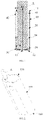
- the structure of the aerosol generating device of this embodiment is shown in FIG. 1 , and the aerosol generating device comprises:
- the inner diameter of the chamber 20 is larger than the outer diameter of the smokable material A in order to facilitate the smooth receiving and removing operations of the smokable material A in the chamber 20; when the smokable material A is inserted into the chamber 20, there is a certain gap 30 between the inner surface of the chamber 20 and the outer surface of the smokable material A.
- an air inlet 13 is provided on the distal end 12 to allow external air to enter the outer housing 10 during smoking.
- the airflow circulation path is shown by an arrow R1 in FIG. 1 , the external air enters the chamber 20 from the air inlet 13 and passes through the smokable material A until it is smoked by the user.
- the aerosol generating device is further provided with a first spacer 40 for preventing the air in the chamber 20 from leaving the chamber 20 through the gap 30.
- the first spacer 4 is filled in the gap 30 and is located near the proximal end 11, and it is arranged around a part of the outer surface of the smokable material A so as to prevent the air in the gap 30 from leaving the chamber 20 in the way indicated by an arrow R2 in FIG. 1 .
- the aerosol generating device is also provided with a second spacer 50, the second spacer 50 is filled in the gap 30 and is located near the distal end 12, and it is used for preventing the air in the gap 30 from entering the smokable material A from the end of the smokable material A opposite to the distal end 12 in the way indicated by an arrow R3 in FIG. 1 .
- the present application further provides an aerosol generating device according to another embodiment, and the structure thereof is shown in FIG. 2 to FIG. 5 , and the aerosol generating device comprises:
- the end cap 120 is provided with an opening 121 thereon, and the position of the opening 121 is opposite to the cavity 140 of the heating pipe 130, so that the smokable material A can be at least partially received in the cavity 140 or removed from the cavity 140 through the opening 121.
- the heating pipe 130 comprises a first end 131, a second end 132 and a hollow central portion, the hollow central portion forms the cavity 140, and the cavity 140 and the opening 121 form the chamber of the aerosol generating device for receiving the smokable material A.
- the distal end 120 of the outer housing 100 is provided thereon with an air inlet (not labeled in the figure) opposite to the second end 132, which is used to take air into the cavity 140 when the user smokes.
- the outer housing 100 is further provided therein with a spacer 150, the spacer 150 is used for airflow isolation and prevents the air in the cavity 140 from leaving the outer housing 100 in a way other than passing through the smokable material A.
- the spacer 150 is arranged at the first end 131, which may prevent the air in the cavity 140 from escaping from the gap 160 between the inner surface of the heating pipe 130 and the outer sidewall of the smokable material A as shown by the arrow R2 in FIG. 5 until it leaves the outer housing 100. Therefore, it is ensured that during smoking, the volatile substances generated by the smokable material A after being heated can only leave the outer housing 100 through pores inside the smokable material A according to the arrow R1 in FIG. 5 , until they are filtered by the filter at the top of the smokable material A and smoked by the user.
- the spacer 150 mainly comprises a ring-shaped mounting part 151 which is convenient for mounting, and a blocking part 152 extending from the mounting part 151.
- the blocking part 152 is ring-shaped and has a through hole 153 through which the smokable material A passes, so that the smokable material A is smoothly received in or removed from the cavity 140.
- the blocking part 152 abuts against the outer surface of the smokable material A, thereby realizing air isolation and preventing the air in the cavity 140 from escaping.
- the size of the diameter of the through hole 153 may be preferably designed according to the interference effect of 0.1 mm to 0.5 mm.
- the spacer 150 is made of flexible materials, such as silica gel, flexible resin or the like.
- the end cap 120 is provided thereon with a flange 122 extending toward the heating pipe 130, and the mounting part 151 is annularly sleeved on the flange 122 for mounting and fixing.
- the blocking part 152 is provided thereon with a notch 154 extending along the radial direction of the through hole 153, which makes the blocking part 152 more deformable and easier to deform, and reduces the friction force between the smokable material A and the blocking part 152, thus facilitating the insertion or removal operations of the smokable material A.
- the notch 154 may also be implemented with a similar slit structure or the like.
- the width of the notch 154 or the slit is controlled to be 0.05 mm to 1 mm in practice, and at the same time, the notch 154 or the slit has an appropriate airtightness effect.
- the smokable material A comprises a specially-made cylindrical cigarette, specifically as shown in FIG. 7 , and comprises a filter 171, a cooling filler 172, a tobacco material 173, and an outer wrapping paper 174 which are axially assembled in sequence along the axial direction.
- the tobacco material 173 releases volatile substances when heated, and the volatile substances are smoked after being cooled and filtered by the cooling filler 172 and the filter 171.
- the outer wrapping paper 174 is made of hemp pulp mixed with partially bleached wood pulp or straw pulp as the raw material, and after high viscosity beating and adding fillers (such as calcium carbonate), the outer wrapping paper 174 is made by being pressed with a watermark roller on a paper machine or a dry roller outside the machine.
- the above heating pipe 130 may be directly made of materials with appropriate resistivity, and after being connected with a power supply (not shown in the figure) through conductive structures such as leads, pins and conductive terminals, the heating pipe 130 is powered by the power supply to heat the smokable material A.
- Suitable materials may comprise pure nickel alloy, nickel-chromium alloy, nickel-iron alloy, iron-chromium alloy, iron-chromium aluminum alloy, titanium alloy or stainless steel or the like.
- the structure of the heating part of the aerosol generating device may be shown in FIG. 8 , the heating part comprises a tubular susceptor 230, and the hollow portion in the tubular susceptor 230 forms a cavity 240 for containing the smokable material A; a tubular support 231 is nested outside the tubular susceptor 230, and an electromagnetic coil 232 is wound around the tubular support 231.
- the electromagnetic coil 232 is used to generate a changing magnetic field, and the tubular susceptor 230 is made of a material with appropriate magnetic permeability and it may generate heat when penetrated by the changing magnetic field, so as to heat the smokable material A contained inside.
- the aerosol generating device uses the heating pipe 330 shown in FIG. 9 to heat the smokable material A.
- the heating pipe 330 is provided therein with a blocking part 352 extending from the inner wall into the hollow cavity, and the blocking part 352b is close to the first end 331 for abutting against the outer surface of the smokable material A to prevent the air in the heating pipe 330 from escaping from the first end 331.
- the blocking part 352 has a through hole 353 through which the smokable material A passes, and a notch 354 extending in the radial direction, so as to reduce the friction coefficient between the smokable material A and the blocking part 352, thereby facilitating the insertion or removal operations of the smokable material A.
- the blocking part 352 may be arranged in the opening 121 of the end cap 120 similar to that of FIG. 4 , and is integrally arranged with the end cap 120 as a part of the end cap 120.
- the present application further provides an aerosol generating device of another embodiment.
- the structure of the aerosol generating device of this embodiment is shown in FIG. 10 , and the aerosol generating device comprises:
- a material support frame 460 which is preferably made of temperature-resistant material such as temperature-resistant plastic, is further provided in the outer housing 410, and it at least partially extends into the heating pipe 430.
- an isolation structure that may be manually or automatically operated by a user is also proposed, as shown in FIG. 11 to FIG. 14 .
- a tubular heating element 510 In the structure shown in FIG. 11 to FIG. 14 , there is a tubular heating element 510, and the space in the tubular heating element 510 forms an accommodating cavity 511 for receiving the smokable material A such as cigarettes.
- the tubular heating element 510 is assembled in the outer housing (not shown in the figure) of the aerosol generating device.
- the tubular heating element 510 has an open end 520 through which the smokable material A can be received into or removed from the accommodating cavity 511.
- At least one movable spacer 550 is provided at the open end 520, and the spacer 550 may be actuated manually or electrically by a user to move. Therefore, when the smokable material A is received and heated in the accommodating cavity 511, it is possible to prevent the air in the gap between the outer sidewall of the smokable material A and the accommodating cavity 511 from escaping by moving the spacer 550 to be around the outer periphery of the smokable material A and moderately abut against the outer sidewall of the smokable material A.
- the spacer 550 may be further driven to move, so that it can move away from the outer sidewall of the smokable material A to release the smokable material A, thereby facilitating the removal operation of the smokable material A.
- the states are shown in FIG. 13 and FIG. 14 respectively.
- FIG. 12 to FIG. 14 there are five spacers 550, which are arranged around the central axis of the tubular heating element 510 in sequence to form a surrounding space 552 located at the center of the spacers 550, and the smokable material A is received into the accommodating cavity 511 after passing through the surrounding space 552.
- actuating mode of the movement of the at least one spacer 550 and related functional components described above comprise:
- the gelatinized substances in the gap between the smokable material and the heating tube can be prevented from escaping outside the housing or entering the smokable material when the user smokes, thereby ensuring a good smoking taste.
Landscapes
- Catching Or Destruction (AREA)
- Cigarettes, Filters, And Manufacturing Of Filters (AREA)
Abstract
Description
- Embodiments of the present application relate to the field of heat-not-burning smoking sets, and in particular, relate to an aerosol generating device.
- Tobacco products (e.g., cigarettes, cigars, etc.) burn tobacco to produce tobacco smoke during use. People have attempted to replace these tobacco-burning products by making products that release compounds without burning.
- Examples of such products are heating devices that release compounds by heating rather than burning materials. For example, the materials may be tobacco or other non-tobacco products, and the non-tobacco products may or may not contain nicotine. As another example, there are aerosol providing products, such as a so-called low-temperature baking smoking set. A known low-temperature baking smoking set usually comprises a heating cavity for receiving and heating tobacco products. When the tobacco products are received and heated in the heating cavity, aerosol for smoking is generated. However, the outer wrapping paper of the tobacco products will be gelatinized when it is heated, and the gelatinized substances will escape from the heating cavity, which affects the smoking experience of users.
- In order to solve the problem in the prior art that gelatinized substances of the tobacco outer wrapping paper affect the smoking experience, embodiments of the present application provide an aerosol generating device.
- An aerosol generating device of an embodiment of the present application is configured to heat a smokable material to volatilize at least one component of the smokable material, and the aerosol generating device comprises:
- a chamber, configured to receive the smokable material and maintain a gap with an outer sidewall of the smokable material;
- a heating element, configured to heat the smokable material received in the chamber; and
- at least one spacer, at least partially extending into the chamber at least when the smokable material is received in the chamber, so as to prevent air in the gap from escaping from the chamber when the heating element heats the smokable material, or prevent the air in the gap from entering the smokable material through an end of the smokable material received in the chamber when the heating element heats the smokable material.
- Preferably, the spacer comprises a blocking part which at least partially extends into the chamber and is able to abut against the outer sidewall of the smokable material.
- Preferably, the blocking part is provided thereon with a strength reduction structure, so that the blocking part has greater deformation capacity to reduce the friction force with the outer sidewall of the smokable material.
- Preferably, the strength reduction structure comprises a notch or slit extending along a radial direction of the chamber.
- Preferably, the width of the notch or slit is from 0.05 mm to 1 mm.
- Preferably, the heating element has a tubular shape and comprises a first end and a second end opposite to each other and a hollow central portion; the hollow central portion forms the chamber for receiving the smokable material; and
the spacer is configured to prevent the air in the gap from leaving the chamber through at least one of the first end and the second end. - Preferably, the heating element is a resistance heater or is configured to heat by penetration of a changing magnetic field.
- Preferably, the chamber comprises a proximal end and a distal end opposite to each other, and an opening at the proximal end; in use, the smokable material is removably received in the chamber through the opening.
- Preferably, the spacer comprises at least one first spacer disposed adjacent to the proximal end.
- Preferably, the spacer comprises at least one second spacer disposed adjacent to the distal end.
- Preferably, the spacer is ring-shaped.
- Preferably, the spacer is able to be configured between a first configuration and a different second configuration; wherein,
- in the first configuration, the spacer at least partially extends into the chamber and abuts against the outer sidewall of the smokable material received in the chamber, thereby closing the gap to prevent the air in the gap from escaping from the chamber, or preventing the air in the gap from entering the smokable material through an end of the smokable material received in the chamber; and
- in the second configuration, the spacer releases abutment with the outer sidewall of the smokable material.
- By adopting the aerosol generating device described above, gelatinized substances in the gap can be prevented from escaping out of the device or entering into the smokable material when the user smokes, thereby ensuring a good smoking taste.
- In order to more clearly illustrate technical solutions in embodiments of the present application, attached drawings required in the description of the embodiments will be briefly introduced hereinafter. Obviously, the attached drawings in the following description are only some embodiments of the present application. For those of ordinary skill in the art, other attached drawings can be obtained according to the structures shown in these drawings without creative labors.
-
FIG. 1 is a schematic view of an aerosol generating device provided by an embodiment. -
FIG. 2 is a schematic view of an aerosol generating device provided by another embodiment. -
FIG. 3 is a schematic sectional view of the structure of the aerosol generating device shown inFIG. 2 . -
FIG. 4 is a schematic exploded view of the structure of the aerosol generating device shown inFIG. 3 . -
FIG. 5 is an enlarged schematic view of a part B inFIG. 3 . -
FIG. 6 is a schematic structural diagram of a spacer inFIG. 3 to FIG. 5 . -
FIG. 7 is a schematic structural diagram of a smokable material provided by an embodiment. -
FIG. 8 is a schematic structural diagram of a heating assembly in an aerosol generating device according to another embodiment. -
FIG. 9 is a schematic structural diagram of a heating pipe in an aerosol generating device according to another embodiment. -
FIG. 10 is a schematic structural diagram of an aerosol generating device according to another embodiment. -
FIG. 11 is a schematic structural diagram of an aerosol generating device according to another embodiment. -
FIG. 12 is a schematic view of a component driving the spacer to move inFIG. 11 . -
FIG. 13 is a schematic view of the spacer ofFIG. 12 in a state of releasing the smokable material. -
FIG. 14 is a schematic view of the spacer ofFIG. 13 in a state of moving to abut against the smokable material. - In order to facilitate the understanding of the present application, the application will be described in more detail below with reference to the attached drawings and specific embodiments. It shall be noted that, when an element is expressed as "fixed to"/"fixedly connected to" another element, it may be directly on another element, or there may be one or more intermediate elements therebetween. When an element is expressed as "connected" to another element, it may be directly connected to another element, or there may be one or more intervening elements therebetween. Terms such as "vertical", "horizontal", "left", "right", "inside", "outside" and similar expressions used in this specification are used for illustrative purposes only.
- Unless otherwise defined, all technical and scientific terms used in this specification have the same meanings as those commonly understood by those skilled in the art of the present application. Terms used in the specification of the present application are only for the purpose of describing specific embodiments, and are not used to limit the present application. The term "and/or" used in this specification comprises any and all combinations of one or more associated listed items.
- In addition, technical features involved in different embodiments of the present application described below may be combined with each other as long as they do not conflict with each other.
- In this specification, the "installation" comprises fixing or restricting a certain element or device to a specific position or place by means of welding, screwing, clamping, bonding or the like. The element or device may remain stationary at the specific position or place or move within a limited range, and the element or device can or cannot be disassembled after being fixed or restricted to the specific position or place, which is not limited in the embodiments of the present application.
- An embodiment of the present application provides an aerosol generating device, which is used to heat a smokable material to release at least one volatile compound from the smokable material. The structure of the aerosol generating device of this embodiment is shown in
FIG. 1 , and the aerosol generating device comprises: - an
outer housing 10, serving as a housing component of the device and accommodating and installing various functional structures inside; and theouter housing 10 has aproximal end 11 and adistal end 12 opposite to each other; wherein theproximal end 11 is configured as an end for the user to install and remove the smokable material A and smoke, while thedistal end 12 is the other end away from the user; and - a
chamber 20, used for receiving and heating at least a part of the smokable material A. - Of course, the inner diameter of the
chamber 20 is larger than the outer diameter of the smokable material A in order to facilitate the smooth receiving and removing operations of the smokable material A in thechamber 20; when the smokable material A is inserted into thechamber 20, there is acertain gap 30 between the inner surface of thechamber 20 and the outer surface of the smokable material A. - In order to facilitate the smooth circulation of airflow during smoking, an
air inlet 13 is provided on thedistal end 12 to allow external air to enter theouter housing 10 during smoking. During smoking, the airflow circulation path is shown by an arrow R1 inFIG. 1 , the external air enters thechamber 20 from theair inlet 13 and passes through the smokable material A until it is smoked by the user. - Further, the aerosol generating device is further provided with a
first spacer 40 for preventing the air in thechamber 20 from leaving thechamber 20 through thegap 30. Furthermore, it can be seen from the embodiment shown inFIG. 1 that the first spacer 4 is filled in thegap 30 and is located near theproximal end 11, and it is arranged around a part of the outer surface of the smokable material A so as to prevent the air in thegap 30 from leaving thechamber 20 in the way indicated by an arrow R2 inFIG. 1 . - Furthermore, the aerosol generating device is also provided with a
second spacer 50, thesecond spacer 50 is filled in thegap 30 and is located near thedistal end 12, and it is used for preventing the air in thegap 30 from entering the smokable material A from the end of the smokable material A opposite to thedistal end 12 in the way indicated by an arrow R3 inFIG. 1 . - The present application further provides an aerosol generating device according to another embodiment, and the structure thereof is shown in
FIG. 2 to FIG. 5 , and the aerosol generating device comprises: - an
outer housing 100, installed with various functional components inside, having aproximal end 110 and adistal end 120 opposite to each other; - an
end cap 120, disposed at theproximal end 110 of theouter housing 100; - a
heating pipe 130, disposed in theouter housing 100; acavity 140 in theheating pipe 130 is used to receive at least a part of the smokable material A. - It can also be seen from
FIG. 4 that, theend cap 120 is provided with anopening 121 thereon, and the position of theopening 121 is opposite to thecavity 140 of theheating pipe 130, so that the smokable material A can be at least partially received in thecavity 140 or removed from thecavity 140 through theopening 121. - In the preferred embodiment shown in
FIG. 4 andFIG. 5 , theheating pipe 130 comprises afirst end 131, asecond end 132 and a hollow central portion, the hollow central portion forms thecavity 140, and thecavity 140 and theopening 121 form the chamber of the aerosol generating device for receiving the smokable material A. In practice, thedistal end 120 of theouter housing 100 is provided thereon with an air inlet (not labeled in the figure) opposite to thesecond end 132, which is used to take air into thecavity 140 when the user smokes. - Further, the
outer housing 100 is further provided therein with aspacer 150, thespacer 150 is used for airflow isolation and prevents the air in thecavity 140 from leaving theouter housing 100 in a way other than passing through the smokable material A. Thespacer 150 is arranged at thefirst end 131, which may prevent the air in thecavity 140 from escaping from thegap 160 between the inner surface of theheating pipe 130 and the outer sidewall of the smokable material A as shown by the arrow R2 inFIG. 5 until it leaves theouter housing 100. Therefore, it is ensured that during smoking, the volatile substances generated by the smokable material A after being heated can only leave theouter housing 100 through pores inside the smokable material A according to the arrow R1 inFIG. 5 , until they are filtered by the filter at the top of the smokable material A and smoked by the user. - Based on the preferred embodiment of
FIG. 5 and FIG. 6 , thespacer 150 mainly comprises a ring-shaped mountingpart 151 which is convenient for mounting, and a blockingpart 152 extending from the mountingpart 151. Of course, based on function realization, the blockingpart 152 is ring-shaped and has a throughhole 153 through which the smokable material A passes, so that the smokable material A is smoothly received in or removed from thecavity 140. Furthermore, when the smokable material A is received in thecavity 140, the blockingpart 152 abuts against the outer surface of the smokable material A, thereby realizing air isolation and preventing the air in thecavity 140 from escaping. - In the preferred embodiments, if the diameter of the through
hole 153 is smaller than the outer diameter of the smokable material A, it may be beneficial to maintain the isolation effect. In practice, the size of the diameter of the throughhole 153 may be preferably designed according to the interference effect of 0.1 mm to 0.5 mm. Of course, based on the optimized airtightness isolation effect, thespacer 150 is made of flexible materials, such as silica gel, flexible resin or the like. - Further, according to the preferred embodiment shown in
FIG. 5 and FIG. 6 , theend cap 120 is provided thereon with aflange 122 extending toward theheating pipe 130, and the mountingpart 151 is annularly sleeved on theflange 122 for mounting and fixing. In addition, the blockingpart 152 is provided thereon with anotch 154 extending along the radial direction of the throughhole 153, which makes the blockingpart 152 more deformable and easier to deform, and reduces the friction force between the smokable material A and the blockingpart 152, thus facilitating the insertion or removal operations of the smokable material A. Of course, based on the similar effect of reducing the rigidity strength of the blockingpart 152, thenotch 154 may also be implemented with a similar slit structure or the like. At the same time, the width of thenotch 154 or the slit is controlled to be 0.05 mm to 1 mm in practice, and at the same time, thenotch 154 or the slit has an appropriate airtightness effect. - In an embodiment, the smokable material A comprises a specially-made cylindrical cigarette, specifically as shown in
FIG. 7 , and comprises afilter 171, a coolingfiller 172, atobacco material 173, and anouter wrapping paper 174 which are axially assembled in sequence along the axial direction. Thetobacco material 173 releases volatile substances when heated, and the volatile substances are smoked after being cooled and filtered by the coolingfiller 172 and thefilter 171. In an embodiment, theouter wrapping paper 174 is made of hemp pulp mixed with partially bleached wood pulp or straw pulp as the raw material, and after high viscosity beating and adding fillers (such as calcium carbonate), theouter wrapping paper 174 is made by being pressed with a watermark roller on a paper machine or a dry roller outside the machine. - In an embodiment, the
above heating pipe 130 may be directly made of materials with appropriate resistivity, and after being connected with a power supply (not shown in the figure) through conductive structures such as leads, pins and conductive terminals, theheating pipe 130 is powered by the power supply to heat the smokable material A. Suitable materials may comprise pure nickel alloy, nickel-chromium alloy, nickel-iron alloy, iron-chromium alloy, iron-chromium aluminum alloy, titanium alloy or stainless steel or the like. - In another embodiment, the structure of the heating part of the aerosol generating device may be shown in
FIG. 8 , the heating part comprises atubular susceptor 230, and the hollow portion in thetubular susceptor 230 forms acavity 240 for containing the smokable material A; atubular support 231 is nested outside thetubular susceptor 230, and anelectromagnetic coil 232 is wound around thetubular support 231. Theelectromagnetic coil 232 is used to generate a changing magnetic field, and thetubular susceptor 230 is made of a material with appropriate magnetic permeability and it may generate heat when penetrated by the changing magnetic field, so as to heat the smokable material A contained inside. - In another embodiment of the present application, the aerosol generating device uses the
heating pipe 330 shown inFIG. 9 to heat the smokable material A. Theheating pipe 330 is provided therein with a blockingpart 352 extending from the inner wall into the hollow cavity, and the blocking part 352b is close to thefirst end 331 for abutting against the outer surface of the smokable material A to prevent the air in theheating pipe 330 from escaping from thefirst end 331. Similarly, the blockingpart 352 has a throughhole 353 through which the smokable material A passes, and anotch 354 extending in the radial direction, so as to reduce the friction coefficient between the smokable material A and the blockingpart 352, thereby facilitating the insertion or removal operations of the smokable material A. - Of course, in other modified embodiments, the blocking
part 352 may be arranged in theopening 121 of theend cap 120 similar to that ofFIG. 4 , and is integrally arranged with theend cap 120 as a part of theend cap 120. - The present application further provides an aerosol generating device of another embodiment. The structure of the aerosol generating device of this embodiment is shown in
FIG. 10 , and the aerosol generating device comprises: - an
outer housing 410; - a
heating pipe 430, inside which a cavity for receiving and heating the smokable material A is formed, and there is acertain gap 440 between the smokable material A and the inner wall of theheating pipe 430; - a
spacer 450, arranged near asecond end 432, and configured to prevent the air in thegap 440 from entering the smokable material A from the end of the smokable material A opposite to thesecond end 432 as shown by the arrow R3; thereby ensuring that only external air can enter the smokable material A according to the path indicated by an arrow R4 inFIG. 9 during smoking. - Of course, it can also be seen from
FIG. 10 that in order to ensure that the smokable material A can be fixed and maintained after being received in theheating pipe 430, amaterial support frame 460, which is preferably made of temperature-resistant material such as temperature-resistant plastic, is further provided in theouter housing 410, and it at least partially extends into theheating pipe 430. When the smokable material A is received in theheating pipe 430, it abuts on thematerial support frame 460 to remain fixed. - In an aerosol generating device of another embodiment, an isolation structure that may be manually or automatically operated by a user is also proposed, as shown in
FIG. 11 to FIG. 14 . In the structure shown inFIG. 11 to FIG. 14 , there is atubular heating element 510, and the space in thetubular heating element 510 forms anaccommodating cavity 511 for receiving the smokable material A such as cigarettes. Of course, thetubular heating element 510 is assembled in the outer housing (not shown in the figure) of the aerosol generating device. - Further, the
tubular heating element 510 has anopen end 520 through which the smokable material A can be received into or removed from theaccommodating cavity 511. At least onemovable spacer 550 is provided at theopen end 520, and thespacer 550 may be actuated manually or electrically by a user to move. Therefore, when the smokable material A is received and heated in theaccommodating cavity 511, it is possible to prevent the air in the gap between the outer sidewall of the smokable material A and theaccommodating cavity 511 from escaping by moving thespacer 550 to be around the outer periphery of the smokable material A and moderately abut against the outer sidewall of the smokable material A. - After completing the smoking, in order to facilitate the removal of the smokable material A, the
spacer 550 may be further driven to move, so that it can move away from the outer sidewall of the smokable material A to release the smokable material A, thereby facilitating the removal operation of the smokable material A. The states are shown inFIG. 13 andFIG. 14 respectively. - In the embodiment shown in
FIG. 12 to FIG. 14 , there are fivespacers 550, which are arranged around the central axis of thetubular heating element 510 in sequence to form a surroundingspace 552 located at the center of thespacers 550, and the smokable material A is received into theaccommodating cavity 511 after passing through the surroundingspace 552. - Further, the actuating mode of the movement of the at least one
spacer 550 and related functional components described above comprise: - a
knob 540 for actuating, capable of rotating around the central axis of thetubular heating element 510; - the
spacer 550, hinged with theknob 540 through ahinge part 551; specifically, in the figure, thehinge part 551 is in the form of a hole which may be fitted and assembled with a correspondingcolumnar pin 541 on theknob 540 so as to rotate with each other; therefore, when theknob 540 rotates itself, it can drive thespacer 550 to rotate together, and the movement trend driven by theknob 540 may be shown by an arrow P1 inFIG. 13 andFIG. 14 ; - a
guide bracket 530, fixed in the housing of the aerosol generating device; theguide bracket 530 is provided thereon with aguide groove 531, and the extension direction of theguide groove 531 is biased towards or away from the central axis from the circumferential rotation direction of theknob 540; while thecorresponding spacer 550 is provided thereon with aguide stud 553 which extends into theguide groove 531 to match with theguide groove 531, so that when driven by the rotation of theknob 540, thespacer 550 can rotate towards or away from the central axis relative to theknob 540 with thehinge part 551 as the axis under the guidance of theguide groove 531, as shown by an arrow P2 inFIG. 13 andFIG. 14 . Therefore, thespacer 550 can expand or collapse thesurrounding space 552 under the actuation of theknob 540, thereby changing the state where thespacer 550 abuts against or releases the outer sidewall of the smokable material A, as shown inFIG. 13 andFIG. 14 respectively.FIG. 13 is a schematic view illustrating the state of releasing the abutment with the smokable material A; andFIG. 14 is a schematic view illustrating the state where thespacer 550 abuts against the outer sidewall of the smokable material A when moving to the collapsed position. - By adopting the aerosol generating device of the above embodiment, the gelatinized substances in the gap between the smokable material and the heating tube can be prevented from escaping outside the housing or entering the smokable material when the user smokes, thereby ensuring a good smoking taste.
- It shall be noted that, preferred embodiments of the present application are given in the specification and attached drawings of the present application. However, the present application can be realized in many different forms, and it is not limited to the embodiments described in this specification. These embodiments do not serve as additional restrictions on the content of the present application, but are provided for a more thorough and comprehensive understanding of the disclosure of the present application. Moreover, the above-mentioned technical features continue to be combined with each other to form various embodiments not listed above, which are regarded as within the scope recorded in the specification of the present application. Furthermore, it is possible for those skilled in the art to make improvements or alterations according to the above description, and all these improvements and alterations should be within the scope claimed in the appended claims of the present application.
Claims (11)
- An aerosol generating device, configured to heat a smokable material to volatilize at least one component of the smokable material, and characterized by comprising:a chamber, configured to receive the smokable material and maintain a gap with an outer sidewall of the smokable material;a heating element, configured to heat the smokable material received in the chamber; andat least one spacer, at least partially extending into the chamber at least when the smokable material is received in the chamber, so as to prevent air in the gap from escaping from the chamber when the heating element heats the smokable material, or prevent the air in the gap from entering the smokable material through an end of the smokable material received in the chamber when the heating element heats the smokable material.
- The aerosol generating device according to claim 1, characterized in that, the spacer comprises a blocking part which at least partially extends into the chamber and is able to abut against the outer sidewall of the smokable material.
- The aerosol generating device according to claim 2, characterized in that, the blocking part is provided thereon with a strength reduction structure, so that the blocking part has greater deformation capacity to reduce the friction force with the outer sidewall of the smokable material.
- The aerosol generating device according to claim 3, characterized in that, the strength reduction structure comprises a notch or slit extending along a radial direction of the chamber.
- The aerosol generating device according to claim 4, characterized in that, a width of the notch or slit is from 0.05 mm to 1 mm.
- The aerosol generating device according to any of claims 1 to 4, characterized in that, the heating element has a tubular shape and comprises a first end and a second end opposite to each other and a hollow central portion; the hollow central portion forms the chamber for receiving the smokable material;
the spacer is configured to prevent the air in the gap from leaving the chamber through at least one of the first end and the second end. - The aerosol generating device according to claim 6, characterized in that, the heating element is a resistance heater or is configured to heat by penetration of a changing magnetic field.
- The aerosol generating device according to any of claims 1 to 4, characterized in that, the chamber comprises a proximal end and a distal end opposite to each other, and an opening at the proximal end; in use, the smokable material is removably received in the chamber through the opening.
- The aerosol generating device according to claim 8, characterized in that, the spacer comprises at least one first spacer disposed adjacent to the proximal end; and/or, the spacer comprises at least one second spacer disposed adjacent to the distal end.
- The aerosol generating device according to any of claims 1 to 4, characterized in that, the spacer is ring-shaped.
- The aerosol generating device according to any of claims 1 to 4, characterized in that, the spacer is able to be configured between a first configuration and a different second configuration; wherein,in the first configuration, the spacer at least partially extends into the chamber and abuts against the outer sidewall of the smokable material received in the chamber, thereby closing the gap to prevent the air in the gap from escaping from the chamber, or preventing the air in the gap from entering the smokable material through an end of the smokable material received in the chamber; andin the second configuration, the spacer releases abutment with the outer sidewall of the smokable material.
Applications Claiming Priority (2)
| Application Number | Priority Date | Filing Date | Title |
|---|---|---|---|
| CN201910834914.0A CN112535320A (en) | 2019-09-05 | 2019-09-05 | Aerosol generator |
| PCT/CN2020/113582 WO2021043283A1 (en) | 2019-09-05 | 2020-09-04 | Aerosol generating device |
Publications (2)
| Publication Number | Publication Date |
|---|---|
| EP4026446A1 true EP4026446A1 (en) | 2022-07-13 |
| EP4026446A4 EP4026446A4 (en) | 2023-11-01 |
Family
ID=74853148
Family Applications (1)
| Application Number | Title | Priority Date | Filing Date |
|---|---|---|---|
| EP20861622.7A Pending EP4026446A4 (en) | 2019-09-05 | 2020-09-04 | AEROSOL GENERATING DEVICE |
Country Status (6)
| Country | Link |
|---|---|
| US (1) | US12369634B2 (en) |
| EP (1) | EP4026446A4 (en) |
| JP (2) | JP7509864B2 (en) |
| KR (1) | KR102759801B1 (en) |
| CN (1) | CN112535320A (en) |
| WO (1) | WO2021043283A1 (en) |
Families Citing this family (5)
| Publication number | Priority date | Publication date | Assignee | Title |
|---|---|---|---|---|
| CN215347056U (en) * | 2021-03-19 | 2021-12-31 | 深圳市合元科技有限公司 | Heating mechanism and aerosol generating device |
| KR102573818B1 (en) * | 2021-06-23 | 2023-08-31 | 주식회사 케이티앤지 | Device for generating aerosol |
| CN217609545U (en) * | 2022-04-28 | 2022-10-21 | 深圳市合元科技有限公司 | Aerosol product heating assembly and aerosol generating device |
| GB202216128D0 (en) * | 2022-10-31 | 2022-12-14 | Nicoventures Trading Ltd | Heater for an aerosol provision device |
| WO2025134254A1 (en) * | 2023-12-20 | 2025-06-26 | 日本たばこ産業株式会社 | Suction device |
Family Cites Families (20)
| Publication number | Priority date | Publication date | Assignee | Title |
|---|---|---|---|---|
| US5665262A (en) * | 1991-03-11 | 1997-09-09 | Philip Morris Incorporated | Tubular heater for use in an electrical smoking article |
| US6053176A (en) * | 1999-02-23 | 2000-04-25 | Philip Morris Incorporated | Heater and method for efficiently generating an aerosol from an indexing substrate |
| JP4290697B2 (en) * | 2003-05-14 | 2009-07-08 | 日本たばこ産業株式会社 | Cigarette inspection apparatus with filter and inspection method thereof |
| US7647932B2 (en) * | 2005-08-01 | 2010-01-19 | R.J. Reynolds Tobacco Company | Smoking article |
| EA038916B1 (en) * | 2013-12-05 | 2021-11-09 | Филип Моррис Продактс С.А. | Aerosol-generating article with low resistance air flow path |
| CN203860264U (en) * | 2014-05-28 | 2014-10-08 | 王德成 | Feeding bottle suitable for feeding and observing insects |
| CN107205494B (en) * | 2015-02-06 | 2020-09-01 | 菲利普莫里斯生产公司 | Improved extractor for aerosol generating devices |
| EP3397095B1 (en) * | 2015-12-31 | 2020-11-04 | Philip Morris Products S.a.s. | Multi-part electrically heated aerosol-generating system |
| TW201742556A (en) | 2016-05-13 | 2017-12-16 | British American Tobacco Investments Ltd | Apparatus for heating smokable material |
| GB201705888D0 (en) | 2017-04-12 | 2017-05-24 | British American Tobacco Investments Ltd | Apparatus for volatilising smokable material and a smoking article |
| WO2018195901A1 (en) | 2017-04-28 | 2018-11-01 | 深圳唯嘉康健科技有限公司 | Heat-not-burn tobacco product and method for use in controlling heat |
| CN107373777B (en) | 2017-09-08 | 2023-10-03 | 江苏中烟工业有限责任公司 | A heat-not-burn cigarette smoking device that uses thermal atomization liquid droplets for flexible heating |
| CN107495481A (en) * | 2017-09-25 | 2017-12-22 | 江苏中烟工业有限责任公司 | A kind of dual-heated type low temperature cigarette smoking set |
| WO2019081602A1 (en) * | 2017-10-24 | 2019-05-02 | Philip Morris Products S.A. | Aerosol-generating device having holding mechanism |
| CN207653598U (en) * | 2017-12-11 | 2018-07-27 | 湖南中烟工业有限责任公司 | Low temperature smoking set and cigarette |
| CN207721220U (en) * | 2018-01-05 | 2018-08-14 | 湖南中烟工业有限责任公司 | A kind of cigarette improving air flow path and its applicable low temperature smoking set |
| KR102135894B1 (en) | 2018-02-21 | 2020-07-20 | 주식회사 케이티앤지 | Aerosol generating apparatus |
| CN208446615U (en) | 2018-06-07 | 2019-02-01 | 湖南中烟工业有限责任公司 | A low temperature baking cigarette set |
| CN209185760U (en) | 2018-11-02 | 2019-08-02 | 普维思信(北京)科技有限公司 | A kind of intelligent 3D soakage device and its external member heating not burning cigarette |
| US20230354884A1 (en) * | 2019-01-24 | 2023-11-09 | Inno-It Co., Ltd. | Aerosol Generation System |
-
2019
- 2019-09-05 CN CN201910834914.0A patent/CN112535320A/en active Pending
-
2020
- 2020-09-04 KR KR1020227008433A patent/KR102759801B1/en active Active
- 2020-09-04 JP JP2022513628A patent/JP7509864B2/en active Active
- 2020-09-04 WO PCT/CN2020/113582 patent/WO2021043283A1/en not_active Ceased
- 2020-09-04 EP EP20861622.7A patent/EP4026446A4/en active Pending
-
2022
- 2022-03-04 US US17/686,496 patent/US12369634B2/en active Active
-
2024
- 2024-04-04 JP JP2024061046A patent/JP7741921B2/en active Active
Also Published As
| Publication number | Publication date |
|---|---|
| JP7741921B2 (en) | 2025-09-18 |
| CN112535320A (en) | 2021-03-23 |
| US20220183365A1 (en) | 2022-06-16 |
| US12369634B2 (en) | 2025-07-29 |
| WO2021043283A1 (en) | 2021-03-11 |
| JP2024088727A (en) | 2024-07-02 |
| EP4026446A4 (en) | 2023-11-01 |
| KR102759801B1 (en) | 2025-01-23 |
| JP7509864B2 (en) | 2024-07-02 |
| JP2022548514A (en) | 2022-11-21 |
| KR20220043218A (en) | 2022-04-05 |
Similar Documents
| Publication | Publication Date | Title |
|---|---|---|
| US12369634B2 (en) | Aerosol generating device | |
| US20240315324A1 (en) | Apparatus for heating smokable material | |
| JP7102486B2 (en) | A device configured to heat the smoking material, and a method of forming a heater | |
| EP3704968B1 (en) | Device for generating aerosol | |
| AU2017263073B2 (en) | Apparatus for heating smokable material | |
| KR102715651B1 (en) | Apparatus for heating smokable material | |
| US12063964B2 (en) | Apparatus for heating aerosol-generating material | |
| US20060070633A1 (en) | Flow distributor of an electrically heated cigarette smoking system | |
| JP2019518421A (en) | Device for receiving a smoking material | |
| JP2022525971A (en) | Smoking substitute system | |
| JP2023544662A (en) | Aerosol delivery device | |
| US20230025598A1 (en) | Aerosol Generation Device | |
| WO2025194385A1 (en) | Cigarette apparatus | |
| KR20230128310A (en) | Non-flammable aerosol delivery device |
Legal Events
| Date | Code | Title | Description |
|---|---|---|---|
| STAA | Information on the status of an ep patent application or granted ep patent |
Free format text: STATUS: THE INTERNATIONAL PUBLICATION HAS BEEN MADE |
|
| PUAI | Public reference made under article 153(3) epc to a published international application that has entered the european phase |
Free format text: ORIGINAL CODE: 0009012 |
|
| STAA | Information on the status of an ep patent application or granted ep patent |
Free format text: STATUS: REQUEST FOR EXAMINATION WAS MADE |
|
| 17P | Request for examination filed |
Effective date: 20220404 |
|
| AK | Designated contracting states |
Kind code of ref document: A1 Designated state(s): AL AT BE BG CH CY CZ DE DK EE ES FI FR GB GR HR HU IE IS IT LI LT LU LV MC MK MT NL NO PL PT RO RS SE SI SK SM TR |
|
| DAV | Request for validation of the european patent (deleted) | ||
| DAX | Request for extension of the european patent (deleted) | ||
| A4 | Supplementary search report drawn up and despatched |
Effective date: 20230928 |
|
| RIC1 | Information provided on ipc code assigned before grant |
Ipc: A24F 40/46 20200101ALI20230922BHEP Ipc: A24F 40/40 20200101ALI20230922BHEP Ipc: A24F 47/00 20200101AFI20230922BHEP |
|
| STAA | Information on the status of an ep patent application or granted ep patent |
Free format text: STATUS: EXAMINATION IS IN PROGRESS |
|
| 17Q | First examination report despatched |
Effective date: 20250729 |