EP4026441A1 - Aerosol generator and its atomizing element - Google Patents
Aerosol generator and its atomizing element Download PDFInfo
- Publication number
- EP4026441A1 EP4026441A1 EP21216753.0A EP21216753A EP4026441A1 EP 4026441 A1 EP4026441 A1 EP 4026441A1 EP 21216753 A EP21216753 A EP 21216753A EP 4026441 A1 EP4026441 A1 EP 4026441A1
- Authority
- EP
- European Patent Office
- Prior art keywords
- juice
- atomization
- sealing
- sealing part
- push rod
- Prior art date
- Legal status (The legal status is an assumption and is not a legal conclusion. Google has not performed a legal analysis and makes no representation as to the accuracy of the status listed.)
- Granted
Links
Images



Classifications
-
- A—HUMAN NECESSITIES
- A24—TOBACCO; CIGARS; CIGARETTES; SIMULATED SMOKING DEVICES; SMOKERS' REQUISITES
- A24F—SMOKERS' REQUISITES; MATCH BOXES; SIMULATED SMOKING DEVICES
- A24F40/00—Electrically operated smoking devices; Component parts thereof; Manufacture thereof; Maintenance or testing thereof; Charging means specially adapted therefor
- A24F40/40—Constructional details, e.g. connection of cartridges and battery parts
- A24F40/48—Fluid transfer means, e.g. pumps
- A24F40/485—Valves; Apertures
-
- A—HUMAN NECESSITIES
- A24—TOBACCO; CIGARS; CIGARETTES; SIMULATED SMOKING DEVICES; SMOKERS' REQUISITES
- A24F—SMOKERS' REQUISITES; MATCH BOXES; SIMULATED SMOKING DEVICES
- A24F40/00—Electrically operated smoking devices; Component parts thereof; Manufacture thereof; Maintenance or testing thereof; Charging means specially adapted therefor
- A24F40/10—Devices using liquid inhalable precursors
-
- A—HUMAN NECESSITIES
- A24—TOBACCO; CIGARS; CIGARETTES; SIMULATED SMOKING DEVICES; SMOKERS' REQUISITES
- A24F—SMOKERS' REQUISITES; MATCH BOXES; SIMULATED SMOKING DEVICES
- A24F40/00—Electrically operated smoking devices; Component parts thereof; Manufacture thereof; Maintenance or testing thereof; Charging means specially adapted therefor
- A24F40/40—Constructional details, e.g. connection of cartridges and battery parts
- A24F40/46—Shape or structure of electric heating means
-
- A—HUMAN NECESSITIES
- A24—TOBACCO; CIGARS; CIGARETTES; SIMULATED SMOKING DEVICES; SMOKERS' REQUISITES
- A24F—SMOKERS' REQUISITES; MATCH BOXES; SIMULATED SMOKING DEVICES
- A24F15/00—Receptacles or boxes specially adapted for cigars, cigarettes, simulated smoking devices or cigarettes therefor
- A24F15/01—Receptacles or boxes specially adapted for cigars, cigarettes, simulated smoking devices or cigarettes therefor specially adapted for simulated smoking devices or cigarettes therefor
- A24F15/015—Receptacles or boxes specially adapted for cigars, cigarettes, simulated smoking devices or cigarettes therefor specially adapted for simulated smoking devices or cigarettes therefor with means for refilling of liquid inhalable precursors
-
- A—HUMAN NECESSITIES
- A24—TOBACCO; CIGARS; CIGARETTES; SIMULATED SMOKING DEVICES; SMOKERS' REQUISITES
- A24F—SMOKERS' REQUISITES; MATCH BOXES; SIMULATED SMOKING DEVICES
- A24F40/00—Electrically operated smoking devices; Component parts thereof; Manufacture thereof; Maintenance or testing thereof; Charging means specially adapted therefor
- A24F40/40—Constructional details, e.g. connection of cartridges and battery parts
- A24F40/42—Cartridges or containers for inhalable precursors
Definitions
- the present disclosure relates to the technical field of electronic atomization, especially an aerosol generating device and its atomization assembly therein.
- the electronic atomization device has similar appearance and taste with that of cigarettes, but generally does not contain tar, suspended particles, and other harmful components in cigarettes, which greatly reduces the harm on the user. Therefore, it is usually used as a substitute for cigarettes for smoke quit.
- the aerosol generating device usually consists of atomization assembly and power source assembly.
- the juice storage cavity of commercial atomization assembly is closed, and the tobacco juice are often injected into the atomization assembly in advance.
- the tobacco juice tends to leak outside the atomization assembly through the juice guide hole on the atomization core, which will lead to greasy dirt in the use area of the atomization core, resulting in the waste of tobacco juice, thus decreasing the experience of users.
- the main purpose of present disclosure is to provide an aerosol generating device and its atomization assembly therein, which is aimed to solve the problem that the atomization assembly in the prior art tends to leak tobacco juice during standing or transportation process.
- the present disclosure provides an atomization assembly of aerosol generating device.
- the atomization assembly of aerosol generating device comprises a shell, a sealing seat, an atomization core, and a seal.
- the atomization core is provided with two opposite ends. One end of the atomization core is connected to the shell, and the other end of the atomization core is mounted on the sealing seat.
- the shell, the sealing seat, and the atomization core are enclosed to form a juice storage cavity.
- the atomization core is provided with a passing juice orifice, wherein the seal includes a sealing part in the juice storage cavity and a push rod connected to the sealing part.
- the sealing part is arranged surround peripheral surface of the atomization core for covering the passing juice orifice, and free end of the push rod is slidably arranged through the sealing seat and exposed outside the sealing seat.
- the sealing part is sleeved on the outer peripheral surface of atomization core.
- the sealing part is arranged in a round platform tubular shape.
- the sealing part comprises two push rods, and the two push rods are symmetrically arranged with each other.
- the push rod is integrally formed with the sealing part.
- the sealing seat comprises a silicone pad that is airtight connected to the shell.
- the silicone pad is provided with a mounting hole for the push rod to pass through, and the push rod is interference fit with the mounting hole.
- the shell comprises a shell body, a juice sealing plug, and an outer cover.
- a juice injection hole is provided on the top of the shell body.
- the juice sealing plug is arranged at the juice injection hole.
- the outer cover is connected to the shell body in buckle connection and cover the juice sealing plug.
- the present disclosure further provides an aerosol generating device, which comprises a power supply assembly and above-mentioned atomization assembly, and the atomization assembly is mounted on the power supply assembly.
- the atomization assembly of aerosol generating device comprises a shell, a sealing seat, an atomization core, and a seal.
- the atomization core is provided with two opposite ends. One end of the atomization core is connected to the shell, and the other end of the atomization core is mounted on the sealing seat.
- the shell, the sealing seat, and the atomization core are enclosed to form a juice storage cavity.
- the atomization core is provided with a passing juice orifice, wherein the seal includes a sealing part in the juice storage cavity and a push rod connected to the sealing part.
- the sealing part is arranged surround peripheral surface of the atomization core for covering the passing juice orifice, and free end of the push rod is slidably arranged through the sealing seat and exposed outside the sealing seat.
- the sealing part of the seal covers the passing juice orifice in the juice storage cavity to avoid leakage of tobacco juice out of the atomization assembly through the passing juice orifice during long time standing or transportation. Leakage of tobacco juice will lead to the waste of juice and surface staining on the atomization assembly, which will negatively affect the user's experience.
- the atomization assembly is needed, the user pushes the push rod and drives the sealing part to move to achieve the exposing the passing juice orifice.
- the sealing part is driven to move by pulling the push rod, so that the sealing part can close the passing juice orifice again, which facilitate the improvement of the user's experience on the atomization assembly.
- first and second are merely used for description and cannot be understood to indicate or imply relative importance or implicitly indicate the number of the indicated technical features. Therefore, features with a limitation of “first” or “second” can explicitly or implicitly include one or more features. Furthermore, technical schemes of various embodiments can be combined with each other if only it can be implemented by those of ordinary skill in the art. If a combination of technical schemes is conflict or impracticable, the combination should be considered as not exist and not fall in the scope of protection of the present disclosure.
- connection and “fix” should be understood broadly.
- “fix” can be a fixed connection, a detachable connection, or an integral connection.
- “fix” can be a mechanical connection, can also be an electrical connection, can also be a direct connection, can also be an indirect connection by an intermediary, and can also be an internal communication of two elements, unless otherwise clearly limited.
- a person skilled in the art can understand concrete meanings of terms in the present disclosure as per specific circumstances.
- the present disclosure discloses an atomization assembly of aerosol generating device.
- the atomization assembly 100 of aerosol generating device comprises a shell 110, a sealing seat 120, an atomization core 130, and seal 140.
- the atomization core 130 are provided with two opposite ends. One end of the atomization core 130 is connected to the shell 110, and the other end of the atomization core 130 is mounted on the sealing seat 120.
- the shell 110, the sealing seat 120, and the atomization core 130 are enclosed to form a juice storage cavity 150.
- the atomization core 130 is provided with a passing juice orifice 131, wherein the seal 140 comprise a sealing part 141 in the juice storage cavity 150 and a push rod 142 connected to the sealing part 141.
- the sealing part 141 is arranged surround peripheral surface of the atomization core 130 for covering the passing juice orifice 131, and free end of the push rod 142 is slidably arranged through the sealing seat 120 and exposed outside the sealing seat 120.
- the shell 110 has an end with opening.
- the sealing seat 120 is mounted at the open end of the shell 110, and the sealing seat 120 seals the open end of the shell 110.
- the atomization core 130 is located between the shell 110 and the sealing seat 120.
- the atomization core 130 is hollow to form an air flow channel.
- the shell 110 is provided with a suction port which communicates with the air flow channel, and the sealing seat 120 is provided with an air hole which communicates with the air flow channel.
- the atomization core 130, the sealing seat 120, and the shell 110 are enclosed to form a juice storage cavity 150.
- the juice storage cavity 150 is used to store the atomization base material.
- the atomization matrix can be tobacco juice, and the atomization core 130 heats the atomization base material to generate aerosol for users to smoke.
- the atomization base material is tobacco juice, which is used as an example.
- the passing juice orifice 131 is arranged on the side wall of the atomization core 130, and the passing juice orifice 131 is arranged along the radial direction of the atomization core 130. Without consideration of the action of the seal 140, the passing juice orifice 131 will communicate with the juice storage cavity 150.
- the sealing part 141 of said seal 140 is arranged inside the juice storage cavity 150.
- the sealing part 141 is abutted against the atomization core 130, and the sealing part 141 closes the passing juice orifice 131 to avoid juice leaking through the passing juice orifice 131 to the outside of the atomization assembly 100 when the atomization assembly 100 is standing or long-distance transportation.
- the leakage may cause the waste of tobacco juice and tobacco juice leakage on the bottom of atomization assembly 100.
- the push rod 142 connects with the sealing part 141, and the free end of the push rod 142 exposes outside the sealing seat 120.
- the push rod 142 can be arranged in a long strip shape, so that the push rod 142 can be slidably connected with the sealing seat 120 and moved along the axial direction of the atomization core 130.
- the push rod 142 is integrally formed with the sealing part 141, which increases the connection strength between the push rod 142 and the sealing part 141, facilitating the structural molding of the seal 140, as well as the push rod 142's driven of said sealing part 141 to move.
- the passing juice orifice 131 is closed inside the juice storage cavity 150 by the sealing part 141, which facilitates long-term storage of the atomization assembly 100 and long-distance transportation of the atomization assembly 100.
- the push rod 142 pushes the sealing part 141 towards the axial direction of the atomization core 130, so that the sealing part 141 is arranged to expose the passing juice orifice 131, thus facilitating the tobacco juice to contact with the heat release element of the atomization core 130 through the passing juice orifice 131to generate aerosol for users to smoke.
- the passing juice orifice 131 is stagger-arranged with the push rod 142, that is, the push rod 142 will not cover the passing juice orifice 131 when the push rod 142 pushes the sealing part 141. Under the action of the sealing part 141 and the push rod 142, the waste of tobacco juice is avoided and the clean appearance of the atomization assembly 100 is guaranteed.
- the push rod 142 outside the atomization assembly 100 is pushed by user and moves towards the atomization core 130, so that the seal 140 moves upward and makes the passing juice orifice 131 communicate with the juice storage cavity 150.
- the push rod 142 can be pulled to move outward, that is, the push rod 142 drives the sealing part 141 to move downward, so that the passing juice orifice 131 can be closed again by the sealing part 141 to avoid leakage of tobacco juice at the passing juice orifice 131 again, which improves the user's experience of atomization assembly 100.
- the sealing part 141 Since the sealing part 141 is always accommodated in the juice storage cavity 150, when the push rod 142 pushes the sealing part 141 to move upward, the sealing part 141 will not lead to the increase of pressure in the juice storage cavity 150, which will lead to leakage of tobacco juice at the passing juice orifice 131.
- the sealing part 141 is sleeved on outer peripheral surface of the atomization core 130.
- the sealing part 141 is arranged in a sleeve shape, that is, the sealing part 141 is hollow, and the side wall of the atomization core 130 is abutted against the inner wall of the sealing part 141 to achieve the effect of closing the passing juice orifice 131.
- the sealing part 141 is arranged in a round platform tubular shape.
- the sealing part 141 is arranged in hollow along the axis direction.
- the sealing part 141 is a plastic part.
- the small diameter end of the sealing part 141 is mounted on the top of the atomization core 130, and the large diameter end of the sealing part 141 is mounted on the bottom of the atomization core 130, which facilitates the push rod 142 to push the sealing part 141 to move upward from the bottom of the sealing part 141.
- the sealing part 141 is arranged in a round table shape, which facilitates tight sealing of the passing juice orifice 131.
- the seal 140 comprises two push rods 142.
- the two push rods 142 are symmetrically arranged with each other, and the push rod 142 and the passing juice orifice 131 are stagger arranged with each other. During the push rod 142 is pushed upward, the push rod 142 is prevented from closing the passing juice orifice 131.
- the two push rods 142 are arranged, so that the push rod 142 can smoothly drive the sealing part 141 to move in the juice storage cavity 150.
- the sealing seat 120 comprises a silicone pad 121, which is airtight connected to the shell 110, the silicone pad 121 is provided with a mounting hole (not shown in the figure) for the push rod 142 to pass through, and the push rod 142 is interference fit with the mounting hole (not shown in the figure).
- the side wall of silicone pad 121 is provided with a plurality of circular convex platforms, and the circular convex platforms are connected with the side wall at the bottom end of the shell 110 to close the bottom end of the sealing seat 120.
- Mounting holes are arranged at the bottom of the silicone pad 121, and the push rod 142 is interference fitted with the mounting hole (not shown in the figure). During the push rod 142 pushes the sealing part 141 along the mounting hole (not shown in the figure) , leakage of tobacco juice from the mounting holes (not shown in the figure) can be avoided.
- the cross-section of the push rod 142 can be a variety of shapes.
- the cross-section of the push rod 142 can be square or circular.
- area of the cross-section of the push rod 142 is increased along the direction away from the sealing part 141. During the push rod 142 is pushed, the push rod 142 still tightly fits with the mounting hole to avoid leakage of tobacco juice.
- the shell 110 comprises a shell body 111, a juice sealing plug 113, and an outer cover 112.
- a juice injection hole 114 is provided on the top of the shell body 111. After tobacco juice is added into the juice storage cavity 150, the juice sealing plug 113 is mounted at the juice injection hole 114.
- the juice sealing plug 113 is made of silica gel material.
- the juice injection hole 114 is closed by the juice sealing plug 113.
- the outer cover 112 is connected to the shell body 111 in buckle connection and covers the juice sealing plug 113.
- the outer cover 112 is arranged in an arc shape, and a concave hole is provided concavely on the shell body 111.
- a clamping platform corresponding to the concave hole is provided convexly on inner wall of the outer cover 112. The concave hole is matched with the clamping platform to make the shell body 111 firmly connect with the outer cover 112.
- the present disclosure further provides an aerosol generating device.
- the aerosol generating device comprises a power supply assembly and above-mentioned atomization assembly 100.
- the atomization assembly 100 is mounted on the power supply assembly, wherein the atomization assembly 100 is detachably connected to the power supply assembly.
- the aerosol generating device adopt all the technical schemes of all above embodiments, therefore have at least all the beneficial effects brought by the technical schemes of the above embodiments, which will not be repeated here.
Landscapes
- Containers And Packaging Bodies Having A Special Means To Remove Contents (AREA)
Abstract
Description
- The present disclosure relates to the technical field of electronic atomization, especially an aerosol generating device and its atomization assembly therein.
- With the gradual improvement of people's awareness on health, people are aware of the harm induced from tobacco on human body, so an electronic atomization device is developed. The electronic atomization device has similar appearance and taste with that of cigarettes, but generally does not contain tar, suspended particles, and other harmful components in cigarettes, which greatly reduces the harm on the user. Therefore, it is usually used as a substitute for cigarettes for smoke quit.
- In prior art, the aerosol generating device usually consists of atomization assembly and power source assembly. At present, the juice storage cavity of commercial atomization assembly is closed, and the tobacco juice are often injected into the atomization assembly in advance. When the electronic cigarette is placed on the counter or transported for a long time, the tobacco juice tends to leak outside the atomization assembly through the juice guide hole on the atomization core, which will lead to greasy dirt in the use area of the atomization core, resulting in the waste of tobacco juice, thus decreasing the experience of users.
- The main purpose of present disclosure is to provide an aerosol generating device and its atomization assembly therein, which is aimed to solve the problem that the atomization assembly in the prior art tends to leak tobacco juice during standing or transportation process.
- To achieve above purpose, the present disclosure provides an atomization assembly of aerosol generating device. The atomization assembly of aerosol generating device comprises a shell, a sealing seat, an atomization core, and a seal. The atomization core is provided with two opposite ends. One end of the atomization core is connected to the shell, and the other end of the atomization core is mounted on the sealing seat. The shell, the sealing seat, and the atomization core are enclosed to form a juice storage cavity. The atomization core is provided with a passing juice orifice, wherein the seal includes a sealing part in the juice storage cavity and a push rod connected to the sealing part. The sealing part is arranged surround peripheral surface of the atomization core for covering the passing juice orifice, and free end of the push rod is slidably arranged through the sealing seat and exposed outside the sealing seat.
- Optionally, the sealing part is sleeved on the outer peripheral surface of atomization core.
- Optionally, the sealing part is arranged in a round platform tubular shape.
- Optionally, the sealing part comprises two push rods, and the two push rods are symmetrically arranged with each other.
- Optionally, the push rod is integrally formed with the sealing part.
- Optionally, the sealing seat comprises a silicone pad that is airtight connected to the shell. The silicone pad is provided with a mounting hole for the push rod to pass through, and the push rod is interference fit with the mounting hole.
- Optionally, the shell comprises a shell body, a juice sealing plug, and an outer cover. A juice injection hole is provided on the top of the shell body. The juice sealing plug is arranged at the juice injection hole. The outer cover is connected to the shell body in buckle connection and cover the juice sealing plug.
- The present disclosure further provides an aerosol generating device, which comprises a power supply assembly and above-mentioned atomization assembly, and the atomization assembly is mounted on the power supply assembly.
- The aerosol generating device and its atomization assembly therein in the technical solution of present disclosure, wherein the atomization assembly of aerosol generating device comprises a shell, a sealing seat, an atomization core, and a seal. The atomization core is provided with two opposite ends. One end of the atomization core is connected to the shell, and the other end of the atomization core is mounted on the sealing seat. The shell, the sealing seat, and the atomization core are enclosed to form a juice storage cavity. The atomization core is provided with a passing juice orifice, wherein the seal includes a sealing part in the juice storage cavity and a push rod connected to the sealing part. The sealing part is arranged surround peripheral surface of the atomization core for covering the passing juice orifice, and free end of the push rod is slidably arranged through the sealing seat and exposed outside the sealing seat. Through arranging the seal, the sealing part of the seal covers the passing juice orifice in the juice storage cavity to avoid leakage of tobacco juice out of the atomization assembly through the passing juice orifice during long time standing or transportation. Leakage of tobacco juice will lead to the waste of juice and surface staining on the atomization assembly, which will negatively affect the user's experience. When the atomization assembly is needed, the user pushes the push rod and drives the sealing part to move to achieve the exposing the passing juice orifice. When the atomization component needs to be standing for a long time again, the sealing part is driven to move by pulling the push rod, so that the sealing part can close the passing juice orifice again, which facilitate the improvement of the user's experience on the atomization assembly.
- For a more complete understanding of present disclosure, or the technical schemes in the prior art, the drawings in the embodiments or the description of the prior art are briefly introduced. Obviously, the drawings in the following descriptions are only some embodiments of present disclosure. It will be apparent to those skilled in the art from this disclosure that other drawings may be easily obtained from these drawings without paying any creative effort.
-
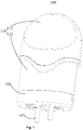
Figure 1 is a stereo structural view of the atomization assembly in the present disclosure. -
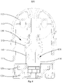
Figure 2 is a schematic diagram of the sectional structure ofFigure 1 . -
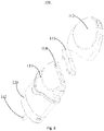
Figure 3 is a disassembled structural schematic ofFigure 1 . -
Figure 4 is a schematic cross-sectional view of the atomization assembly under another status in the present disclosure. -
Figure 5 is a disassembled structural schematic ofFigure 4 . -
Figure 6 is a front structural view of the seal of the atomization assembly in the present disclosure. -
Figure 7 is a stereo structural view of the seal of the atomization assembly in the present disclosure. - The objective realization, functional characteristics, and advantages of the present disclosure will be further described in conjunction with the embodiments and with reference to the drawings.
- Technical solutions according to the embodiments of present disclosure are described clearly and completely in conjunction with the drawings in the embodiments of present disclosure hereinafter. Apparently, the described embodiments are only a few rather than all of the embodiments of present disclosure. Other embodiments obtained without any creative work by those skilled in the art based on the embodiments of the present disclosure fall within the scope of protection of the present disclosure.
- It should be noted that all directional indicators (such as up, down, left, right, front, back, etc.) in the embodiments of present disclosure are only used to explain the relative positions between the components in a specific posture (as shown in the drawings) and movement conditions, etc.. If the specific posture changes, the directional indication also changes accordingly.
- In the description of present application, the "first" and "second" are merely used for description and cannot be understood to indicate or imply relative importance or implicitly indicate the number of the indicated technical features. Therefore, features with a limitation of "first" or "second" can explicitly or implicitly include one or more features. Furthermore, technical schemes of various embodiments can be combined with each other if only it can be implemented by those of ordinary skill in the art. If a combination of technical schemes is conflict or impracticable, the combination should be considered as not exist and not fall in the scope of protection of the present disclosure.
- In the present disclosure, unless otherwise clearly stated and limited, terms "connect" and "fix" should be understood broadly. For instance, "fix" can be a fixed connection, a detachable connection, or an integral connection. Further, "fix" can be a mechanical connection, can also be an electrical connection, can also be a direct connection, can also be an indirect connection by an intermediary, and can also be an internal communication of two elements, unless otherwise clearly limited. A person skilled in the art can understand concrete meanings of terms in the present disclosure as per specific circumstances.
- Refer to
Figure 1 to Figure 7 , the present disclosure discloses an atomization assembly of aerosol generating device. Theatomization assembly 100 of aerosol generating device comprises ashell 110, a sealingseat 120, anatomization core 130, andseal 140. Theatomization core 130 are provided with two opposite ends. One end of theatomization core 130 is connected to theshell 110, and the other end of theatomization core 130 is mounted on the sealingseat 120. Theshell 110, the sealingseat 120, and theatomization core 130 are enclosed to form ajuice storage cavity 150. Theatomization core 130 is provided with a passingjuice orifice 131, wherein theseal 140 comprise a sealingpart 141 in thejuice storage cavity 150 and apush rod 142 connected to the sealingpart 141. The sealingpart 141 is arranged surround peripheral surface of theatomization core 130 for covering the passingjuice orifice 131, and free end of thepush rod 142 is slidably arranged through the sealingseat 120 and exposed outside the sealingseat 120. - Specifically, the
shell 110 has an end with opening. The sealingseat 120 is mounted at the open end of theshell 110, and the sealingseat 120 seals the open end of theshell 110. Theatomization core 130 is located between theshell 110 and the sealingseat 120. Theatomization core 130 is hollow to form an air flow channel. Theshell 110 is provided with a suction port which communicates with the air flow channel, and the sealingseat 120 is provided with an air hole which communicates with the air flow channel. Theatomization core 130, the sealingseat 120, and theshell 110 are enclosed to form ajuice storage cavity 150. Thejuice storage cavity 150 is used to store the atomization base material. The atomization matrix can be tobacco juice, and theatomization core 130 heats the atomization base material to generate aerosol for users to smoke. In this technical scheme, the atomization base material is tobacco juice, which is used as an example. The passingjuice orifice 131 is arranged on the side wall of theatomization core 130, and the passingjuice orifice 131 is arranged along the radial direction of theatomization core 130. Without consideration of the action of theseal 140, the passingjuice orifice 131 will communicate with thejuice storage cavity 150. - In some embodiments, the sealing
part 141 of saidseal 140 is arranged inside thejuice storage cavity 150. The sealingpart 141 is abutted against theatomization core 130, and the sealingpart 141 closes the passingjuice orifice 131 to avoid juice leaking through the passingjuice orifice 131 to the outside of theatomization assembly 100 when theatomization assembly 100 is standing or long-distance transportation. The leakage may cause the waste of tobacco juice and tobacco juice leakage on the bottom ofatomization assembly 100. - It is worth to clarify that one end of the
push rod 142 connects with the sealingpart 141, and the free end of thepush rod 142 exposes outside the sealingseat 120. Thepush rod 142 can be arranged in a long strip shape, so that thepush rod 142 can be slidably connected with the sealingseat 120 and moved along the axial direction of theatomization core 130. Thepush rod 142 is integrally formed with the sealingpart 141, which increases the connection strength between thepush rod 142 and the sealingpart 141, facilitating the structural molding of theseal 140, as well as thepush rod 142's driven of said sealingpart 141 to move. - By adopting above technical scheme, the passing
juice orifice 131 is closed inside thejuice storage cavity 150 by the sealingpart 141, which facilitates long-term storage of theatomization assembly 100 and long-distance transportation of theatomization assembly 100. When theatomization assembly 100 is required, thepush rod 142 pushes the sealingpart 141 towards the axial direction of theatomization core 130, so that the sealingpart 141 is arranged to expose the passingjuice orifice 131, thus facilitating the tobacco juice to contact with the heat release element of theatomization core 130 through the passing juice orifice 131to generate aerosol for users to smoke. The passingjuice orifice 131 is stagger-arranged with thepush rod 142, that is, thepush rod 142 will not cover the passingjuice orifice 131 when thepush rod 142 pushes the sealingpart 141. Under the action of the sealingpart 141 and thepush rod 142, the waste of tobacco juice is avoided and the clean appearance of theatomization assembly 100 is guaranteed. Thepush rod 142 outside theatomization assembly 100 is pushed by user and moves towards theatomization core 130, so that theseal 140 moves upward and makes the passingjuice orifice 131 communicate with thejuice storage cavity 150. - In case the
atomization assembly 100 needs to be standing for a period of time and avoid leakage of tobacco juice at the passingjuice orifice 131, thepush rod 142 can be pulled to move outward, that is, thepush rod 142 drives the sealingpart 141 to move downward, so that the passingjuice orifice 131 can be closed again by the sealingpart 141 to avoid leakage of tobacco juice at the passingjuice orifice 131 again, which improves the user's experience ofatomization assembly 100. - Since the sealing
part 141 is always accommodated in thejuice storage cavity 150, when thepush rod 142 pushes the sealingpart 141 to move upward, the sealingpart 141 will not lead to the increase of pressure in thejuice storage cavity 150, which will lead to leakage of tobacco juice at the passingjuice orifice 131. - In an optional embodiment, the sealing
part 141 is sleeved on outer peripheral surface of theatomization core 130. The sealingpart 141 is arranged in a sleeve shape, that is, the sealingpart 141 is hollow, and the side wall of theatomization core 130 is abutted against the inner wall of the sealingpart 141 to achieve the effect of closing the passingjuice orifice 131. In this embodiment, the sealingpart 141 is arranged in a round platform tubular shape. The sealingpart 141 is arranged in hollow along the axis direction. The sealingpart 141 is a plastic part. The small diameter end of the sealingpart 141 is mounted on the top of theatomization core 130, and the large diameter end of the sealingpart 141 is mounted on the bottom of theatomization core 130, which facilitates thepush rod 142 to push the sealingpart 141 to move upward from the bottom of the sealingpart 141. The sealingpart 141 is arranged in a round table shape, which facilitates tight sealing of the passingjuice orifice 131. - In an optional embodiment, the
seal 140 comprises twopush rods 142. The twopush rods 142 are symmetrically arranged with each other, and thepush rod 142 and the passingjuice orifice 131 are stagger arranged with each other. During thepush rod 142 is pushed upward, thepush rod 142 is prevented from closing the passingjuice orifice 131. The twopush rods 142 are arranged, so that thepush rod 142 can smoothly drive the sealingpart 141 to move in thejuice storage cavity 150. - In an optional embodiment, the sealing
seat 120 comprises asilicone pad 121, which is airtight connected to theshell 110, thesilicone pad 121 is provided with a mounting hole (not shown in the figure) for thepush rod 142 to pass through, and thepush rod 142 is interference fit with the mounting hole (not shown in the figure). In this embodiment, the side wall ofsilicone pad 121 is provided with a plurality of circular convex platforms, and the circular convex platforms are connected with the side wall at the bottom end of theshell 110 to close the bottom end of the sealingseat 120. Mounting holes are arranged at the bottom of thesilicone pad 121, and thepush rod 142 is interference fitted with the mounting hole (not shown in the figure). During thepush rod 142 pushes the sealingpart 141 along the mounting hole (not shown in the figure) , leakage of tobacco juice from the mounting holes (not shown in the figure) can be avoided. - It should be understood that the cross-section of the
push rod 142 can be a variety of shapes. For example, the cross-section of thepush rod 142 can be square or circular. Meanwhile, area of the cross-section of thepush rod 142 is increased along the direction away from the sealingpart 141. During thepush rod 142 is pushed, thepush rod 142 still tightly fits with the mounting hole to avoid leakage of tobacco juice. - In an optional embodiment, the
shell 110 comprises ashell body 111, ajuice sealing plug 113, and anouter cover 112. Ajuice injection hole 114 is provided on the top of theshell body 111. After tobacco juice is added into thejuice storage cavity 150, thejuice sealing plug 113 is mounted at thejuice injection hole 114. Thejuice sealing plug 113 is made of silica gel material. Thejuice injection hole 114 is closed by thejuice sealing plug 113. Theouter cover 112 is connected to theshell body 111 in buckle connection and covers thejuice sealing plug 113. Theouter cover 112 is arranged in an arc shape, and a concave hole is provided concavely on theshell body 111. A clamping platform corresponding to the concave hole is provided convexly on inner wall of theouter cover 112. The concave hole is matched with the clamping platform to make theshell body 111 firmly connect with theouter cover 112. - The present disclosure further provides an aerosol generating device. The aerosol generating device comprises a power supply assembly and above-mentioned
atomization assembly 100. Theatomization assembly 100 is mounted on the power supply assembly, wherein theatomization assembly 100 is detachably connected to the power supply assembly. Referring to above embodiment for specific structure of theatomization assembly 100, the aerosol generating device adopt all the technical schemes of all above embodiments, therefore have at least all the beneficial effects brought by the technical schemes of the above embodiments, which will not be repeated here. - The above only describes preferred embodiments of present disclosure and is not intended to limit the patent scope of present disclosure. Any equivalent structural transformation made by using contents of description and drawings of the present disclosure, or directly or indirectly used in other relevant technical fields under the inventive concept of the present disclosure shall be included within the protection scope of patent of the present disclosure.
| Reference number | Name | | Name | |
| 100 | | 110 | | |
| 111 | | 112 | | |
| 113 | | 114 | | |
| 120 | | 121 | | |
| 130 | Atomizing | 131 | | |
| 140 | | 141 | | |
| 142 | | 150 | Juice storage cavity |
Claims (10)
- An atomization assembly of an aerosol generating device, the atomization assembly comprising:a shell;a sealing seat;an atomization core comprising a first end and a second end, the first end of the atomization core is connected to the shell, and the second end of the atomization core is mounted on the sealing seat, wherein the shell, the sealing seat, and the atomization core are enclosed to form a juice storage cavity, and the atomization core is provided with a passing juice orifice; anda seal comprising a sealing part in the juice storage cavity, and a push rod connected to the sealing part, wherein the sealing part is arranged surrounding an outer peripheral surface of the atomization core for covering the passing juice orifice, and a free end of the push rod is slidably arranged through the sealing seat and exposed outside the sealing seat.
- The atomization assembly of claim 1, wherein the sealing part is sleeved on the outer peripheral surface of the atomization core.
- The atomization assembly of claim 2, wherein the sealing part is arranged in a round platform tubular shape.
- The atomization assembly of claim 1, wherein the sealing part comprises two push rods that are symmetrically arranged with each other.
- The atomization assembly of claim 1, wherein the push rod is integrally formed with the sealing part.
- The atomization assembly of claim 1, wherein the sealing seat comprises a silicone pad that is airtight connected to the shell, wherein the silicone pad comprises a mounting hole for the push rod to pass through, and the push rod is configured to fit with the mounting hole.
- The atomization assembly of claim 1, wherein the shell comprises a shell body, a juice sealing plug, and an outer cover.
- The atomization assembly of claim 7, wherein the shell body comprises a juice injection hole at a top of the shell body.
- The atomization assembly of claim 8, further comprising a juice sealing plug arranged at the juice injection hole, wherein an outer cover is connected to the shell body in buckle connection and covers the juice sealing plug.
- An aerosol generating device comprising:a power supply assembly; andan atomization assembly according to any of claims 1-9.
Applications Claiming Priority (1)
| Application Number | Priority Date | Filing Date | Title |
|---|---|---|---|
| CN202011633543.9A CN112656040A (en) | 2020-12-31 | 2020-12-31 | Aerosol generating device and atomization assembly thereof |
Publications (2)
| Publication Number | Publication Date |
|---|---|
| EP4026441A1 true EP4026441A1 (en) | 2022-07-13 |
| EP4026441B1 EP4026441B1 (en) | 2024-06-19 |
Family
ID=75413268
Family Applications (1)
| Application Number | Title | Priority Date | Filing Date |
|---|---|---|---|
| EP21216753.0A Active EP4026441B1 (en) | 2020-12-31 | 2021-12-22 | Aerosol generator and its atomizing element |
Country Status (3)
| Country | Link |
|---|---|
| US (1) | US20220202081A1 (en) |
| EP (1) | EP4026441B1 (en) |
| CN (1) | CN112656040A (en) |
Families Citing this family (7)
| Publication number | Priority date | Publication date | Assignee | Title |
|---|---|---|---|---|
| CN113331483A (en) * | 2021-07-07 | 2021-09-03 | 深圳市艾维普思科技有限公司 | Atomization assembly and electronic atomization device |
| CN116406840B (en) * | 2021-12-31 | 2025-11-18 | 深圳市大富钦鼎科技有限公司 | An electronic cigarette |
| CN114766722B (en) * | 2022-04-27 | 2025-11-11 | 深圳市斯科尔科技股份有限公司 | Atomizer and atomizing equipment |
| CN220123951U (en) * | 2023-05-16 | 2023-12-05 | 深圳市基克纳科技有限公司 | Atomization device |
| CN219803345U (en) * | 2023-05-18 | 2023-10-10 | 爱奇迹(香港)有限公司 | Atomizing assembly and atomizing device |
| CN222367062U (en) * | 2024-02-23 | 2025-01-21 | 深圳浩瀚阳天科技有限公司 | A push-type double-liquid storage electronic cigarette structure |
| WO2025245853A1 (en) * | 2024-05-31 | 2025-12-04 | 深圳钿瀚投资有限公司 | Atomization cartridge with separated oil and core |
Citations (2)
| Publication number | Priority date | Publication date | Assignee | Title |
|---|---|---|---|---|
| CN110025049A (en) * | 2019-04-25 | 2019-07-19 | 深圳麦克韦尔股份有限公司 | Electronic atomization device and its atomizer assembly and atomizer |
| CN111407000A (en) * | 2019-12-30 | 2020-07-14 | 深圳市艾维普思科技有限公司 | Electronic cigarette atomizing component and electronic cigarette |
Family Cites Families (7)
| Publication number | Priority date | Publication date | Assignee | Title |
|---|---|---|---|---|
| WO2014169467A1 (en) * | 2013-04-18 | 2014-10-23 | Liu Qiuming | Electronic cigarette |
| CN205456077U (en) * | 2016-03-31 | 2016-08-17 | 深圳市合元科技有限公司 | Atomizer and electronic cigarette |
| US20200060343A1 (en) * | 2018-08-21 | 2020-02-27 | Shenzhen Innokin Technology Co., Ltd. | E-cigarette atomization device capable of controlling the supply of e-liquid by relative movement of components |
| CN209251749U (en) * | 2018-09-07 | 2019-08-16 | 深圳市爱卓依科技有限公司 | Electronic cigarette cartridge structure |
| CN209251750U (en) * | 2018-09-07 | 2019-08-16 | 深圳市爱卓依科技有限公司 | Bottom oiling electronic cigarette cartridge |
| CN111434257A (en) * | 2018-12-26 | 2020-07-21 | 常州市派腾电子技术服务有限公司 | Power supply device, electronic cigarette, and assembly method |
| CN213344343U (en) * | 2020-06-10 | 2021-06-04 | 深圳市合元科技有限公司 | Electronic Cigarettes and Electronic Cigarettes |
-
2020
- 2020-12-31 CN CN202011633543.9A patent/CN112656040A/en active Pending
-
2021
- 2021-11-12 US US17/524,815 patent/US20220202081A1/en not_active Abandoned
- 2021-12-22 EP EP21216753.0A patent/EP4026441B1/en active Active
Patent Citations (2)
| Publication number | Priority date | Publication date | Assignee | Title |
|---|---|---|---|---|
| CN110025049A (en) * | 2019-04-25 | 2019-07-19 | 深圳麦克韦尔股份有限公司 | Electronic atomization device and its atomizer assembly and atomizer |
| CN111407000A (en) * | 2019-12-30 | 2020-07-14 | 深圳市艾维普思科技有限公司 | Electronic cigarette atomizing component and electronic cigarette |
Also Published As
| Publication number | Publication date |
|---|---|
| EP4026441B1 (en) | 2024-06-19 |
| US20220202081A1 (en) | 2022-06-30 |
| CN112656040A (en) | 2021-04-16 |
Similar Documents
| Publication | Publication Date | Title |
|---|---|---|
| EP4026441A1 (en) | Aerosol generator and its atomizing element | |
| EP2823720B1 (en) | Atomizer and electronic cigarette having same | |
| CN204444248U (en) | Atomizer and electronic cigarette | |
| CN108308711B (en) | Electronic cigarette atomizer | |
| US9427023B2 (en) | Electronic cigarette and electronic cigarette device | |
| EP4360476A1 (en) | Atomizer and aerosol generating device | |
| EP2801270B1 (en) | Atomizing device and electronic cigarette having same | |
| US10945455B1 (en) | Full glass atomizer | |
| CN216701639U (en) | Atomizer and aerosol generating device | |
| US10701978B2 (en) | Atomizer and electronic cigarette having same | |
| CN111345507A (en) | Electronic cigarette with atomizing seat fixed on battery assembly | |
| US11503859B2 (en) | Electronic atomizing device and atomizer and a liquid injection structure thereof | |
| US20230115358A1 (en) | Atomizer and electronic cigarette | |
| CN204245150U (en) | Inhalator and atomizing component thereof | |
| CN210158011U (en) | Atomizers and Electronic Cigarettes | |
| EP3791738A1 (en) | Atomizing device of an electronic cigarette and an electronic cigarette | |
| CN210695950U (en) | A pod and electronic cigarette with the pod | |
| CN209420958U (en) | Atomizers and Electronic Cigarettes | |
| CN218354593U (en) | Heater, atomizer, and aerosol-generating device | |
| CN210869869U (en) | Oil leakage prevention electronic cigarette | |
| CN213549690U (en) | Electronic cigarette atomizing device | |
| CN212678367U (en) | Aerosol generation device | |
| CN221284672U (en) | Aerosol generating device with child lock function | |
| CN211932547U (en) | Vertical electronic cigarette atomizer structure | |
| CN212590246U (en) | Atomizing device and electron cigarette |
Legal Events
| Date | Code | Title | Description |
|---|---|---|---|
| PUAI | Public reference made under article 153(3) epc to a published international application that has entered the european phase |
Free format text: ORIGINAL CODE: 0009012 |
|
| STAA | Information on the status of an ep patent application or granted ep patent |
Free format text: STATUS: REQUEST FOR EXAMINATION WAS MADE |
|
| 17P | Request for examination filed |
Effective date: 20211222 |
|
| AK | Designated contracting states |
Kind code of ref document: A1 Designated state(s): AL AT BE BG CH CY CZ DE DK EE ES FI FR GB GR HR HU IE IS IT LI LT LU LV MC MK MT NL NO PL PT RO RS SE SI SK SM TR |
|
| GRAP | Despatch of communication of intention to grant a patent |
Free format text: ORIGINAL CODE: EPIDOSNIGR1 |
|
| STAA | Information on the status of an ep patent application or granted ep patent |
Free format text: STATUS: GRANT OF PATENT IS INTENDED |
|
| RIC1 | Information provided on ipc code assigned before grant |
Ipc: A24F 40/485 20200101AFI20231212BHEP |
|
| INTG | Intention to grant announced |
Effective date: 20240116 |
|
| GRAS | Grant fee paid |
Free format text: ORIGINAL CODE: EPIDOSNIGR3 |
|
| GRAA | (expected) grant |
Free format text: ORIGINAL CODE: 0009210 |
|
| STAA | Information on the status of an ep patent application or granted ep patent |
Free format text: STATUS: THE PATENT HAS BEEN GRANTED |
|
| AK | Designated contracting states |
Kind code of ref document: B1 Designated state(s): AL AT BE BG CH CY CZ DE DK EE ES FI FR GB GR HR HU IE IS IT LI LT LU LV MC MK MT NL NO PL PT RO RS SE SI SK SM TR |
|
| REG | Reference to a national code |
Ref country code: GB Ref legal event code: FG4D |
|
| REG | Reference to a national code |
Ref country code: CH Ref legal event code: EP |
|
| REG | Reference to a national code |
Ref country code: DE Ref legal event code: R096 Ref document number: 602021014561 Country of ref document: DE |
|
| PG25 | Lapsed in a contracting state [announced via postgrant information from national office to epo] |
Ref country code: BG Free format text: LAPSE BECAUSE OF FAILURE TO SUBMIT A TRANSLATION OF THE DESCRIPTION OR TO PAY THE FEE WITHIN THE PRESCRIBED TIME-LIMIT Effective date: 20240619 |
|
| PG25 | Lapsed in a contracting state [announced via postgrant information from national office to epo] |
Ref country code: FI Free format text: LAPSE BECAUSE OF FAILURE TO SUBMIT A TRANSLATION OF THE DESCRIPTION OR TO PAY THE FEE WITHIN THE PRESCRIBED TIME-LIMIT Effective date: 20240619 Ref country code: HR Free format text: LAPSE BECAUSE OF FAILURE TO SUBMIT A TRANSLATION OF THE DESCRIPTION OR TO PAY THE FEE WITHIN THE PRESCRIBED TIME-LIMIT Effective date: 20240619 |
|
| REG | Reference to a national code |
Ref country code: LT Ref legal event code: MG9D |
|
| PG25 | Lapsed in a contracting state [announced via postgrant information from national office to epo] |
Ref country code: GR Free format text: LAPSE BECAUSE OF FAILURE TO SUBMIT A TRANSLATION OF THE DESCRIPTION OR TO PAY THE FEE WITHIN THE PRESCRIBED TIME-LIMIT Effective date: 20240920 |
|
| REG | Reference to a national code |
Ref country code: NL Ref legal event code: MP Effective date: 20240619 |
|
| PG25 | Lapsed in a contracting state [announced via postgrant information from national office to epo] |
Ref country code: LV Free format text: LAPSE BECAUSE OF FAILURE TO SUBMIT A TRANSLATION OF THE DESCRIPTION OR TO PAY THE FEE WITHIN THE PRESCRIBED TIME-LIMIT Effective date: 20240619 |
|
| PG25 | Lapsed in a contracting state [announced via postgrant information from national office to epo] |
Ref country code: NO Free format text: LAPSE BECAUSE OF FAILURE TO SUBMIT A TRANSLATION OF THE DESCRIPTION OR TO PAY THE FEE WITHIN THE PRESCRIBED TIME-LIMIT Effective date: 20240919 Ref country code: LV Free format text: LAPSE BECAUSE OF FAILURE TO SUBMIT A TRANSLATION OF THE DESCRIPTION OR TO PAY THE FEE WITHIN THE PRESCRIBED TIME-LIMIT Effective date: 20240619 Ref country code: HR Free format text: LAPSE BECAUSE OF FAILURE TO SUBMIT A TRANSLATION OF THE DESCRIPTION OR TO PAY THE FEE WITHIN THE PRESCRIBED TIME-LIMIT Effective date: 20240619 Ref country code: GR Free format text: LAPSE BECAUSE OF FAILURE TO SUBMIT A TRANSLATION OF THE DESCRIPTION OR TO PAY THE FEE WITHIN THE PRESCRIBED TIME-LIMIT Effective date: 20240920 Ref country code: FI Free format text: LAPSE BECAUSE OF FAILURE TO SUBMIT A TRANSLATION OF THE DESCRIPTION OR TO PAY THE FEE WITHIN THE PRESCRIBED TIME-LIMIT Effective date: 20240619 Ref country code: BG Free format text: LAPSE BECAUSE OF FAILURE TO SUBMIT A TRANSLATION OF THE DESCRIPTION OR TO PAY THE FEE WITHIN THE PRESCRIBED TIME-LIMIT Effective date: 20240619 Ref country code: RS Free format text: LAPSE BECAUSE OF FAILURE TO SUBMIT A TRANSLATION OF THE DESCRIPTION OR TO PAY THE FEE WITHIN THE PRESCRIBED TIME-LIMIT Effective date: 20240919 |
|
| PG25 | Lapsed in a contracting state [announced via postgrant information from national office to epo] |
Ref country code: NL Free format text: LAPSE BECAUSE OF FAILURE TO SUBMIT A TRANSLATION OF THE DESCRIPTION OR TO PAY THE FEE WITHIN THE PRESCRIBED TIME-LIMIT Effective date: 20240619 |
|
| REG | Reference to a national code |
Ref country code: AT Ref legal event code: MK05 Ref document number: 1695330 Country of ref document: AT Kind code of ref document: T Effective date: 20240619 |
|
| PG25 | Lapsed in a contracting state [announced via postgrant information from national office to epo] |
Ref country code: NL Free format text: LAPSE BECAUSE OF FAILURE TO SUBMIT A TRANSLATION OF THE DESCRIPTION OR TO PAY THE FEE WITHIN THE PRESCRIBED TIME-LIMIT Effective date: 20240619 |
|
| PG25 | Lapsed in a contracting state [announced via postgrant information from national office to epo] |
Ref country code: PT Free format text: LAPSE BECAUSE OF FAILURE TO SUBMIT A TRANSLATION OF THE DESCRIPTION OR TO PAY THE FEE WITHIN THE PRESCRIBED TIME-LIMIT Effective date: 20241021 |
|
| PG25 | Lapsed in a contracting state [announced via postgrant information from national office to epo] |
Ref country code: PT Free format text: LAPSE BECAUSE OF FAILURE TO SUBMIT A TRANSLATION OF THE DESCRIPTION OR TO PAY THE FEE WITHIN THE PRESCRIBED TIME-LIMIT Effective date: 20241021 |
|
| PG25 | Lapsed in a contracting state [announced via postgrant information from national office to epo] |
Ref country code: PL Free format text: LAPSE BECAUSE OF FAILURE TO SUBMIT A TRANSLATION OF THE DESCRIPTION OR TO PAY THE FEE WITHIN THE PRESCRIBED TIME-LIMIT Effective date: 20240619 |
|
| PG25 | Lapsed in a contracting state [announced via postgrant information from national office to epo] |
Ref country code: EE Free format text: LAPSE BECAUSE OF FAILURE TO SUBMIT A TRANSLATION OF THE DESCRIPTION OR TO PAY THE FEE WITHIN THE PRESCRIBED TIME-LIMIT Effective date: 20240619 |
|
| PG25 | Lapsed in a contracting state [announced via postgrant information from national office to epo] |
Ref country code: AT Free format text: LAPSE BECAUSE OF FAILURE TO SUBMIT A TRANSLATION OF THE DESCRIPTION OR TO PAY THE FEE WITHIN THE PRESCRIBED TIME-LIMIT Effective date: 20240619 Ref country code: IS Free format text: LAPSE BECAUSE OF FAILURE TO SUBMIT A TRANSLATION OF THE DESCRIPTION OR TO PAY THE FEE WITHIN THE PRESCRIBED TIME-LIMIT Effective date: 20241019 |
|
| PG25 | Lapsed in a contracting state [announced via postgrant information from national office to epo] |
Ref country code: CZ Free format text: LAPSE BECAUSE OF FAILURE TO SUBMIT A TRANSLATION OF THE DESCRIPTION OR TO PAY THE FEE WITHIN THE PRESCRIBED TIME-LIMIT Effective date: 20240619 |
|
| PG25 | Lapsed in a contracting state [announced via postgrant information from national office to epo] |
Ref country code: RO Free format text: LAPSE BECAUSE OF FAILURE TO SUBMIT A TRANSLATION OF THE DESCRIPTION OR TO PAY THE FEE WITHIN THE PRESCRIBED TIME-LIMIT Effective date: 20240619 Ref country code: SK Free format text: LAPSE BECAUSE OF FAILURE TO SUBMIT A TRANSLATION OF THE DESCRIPTION OR TO PAY THE FEE WITHIN THE PRESCRIBED TIME-LIMIT Effective date: 20240619 |
|
| PG25 | Lapsed in a contracting state [announced via postgrant information from national office to epo] |
Ref country code: ES Free format text: LAPSE BECAUSE OF FAILURE TO SUBMIT A TRANSLATION OF THE DESCRIPTION OR TO PAY THE FEE WITHIN THE PRESCRIBED TIME-LIMIT Effective date: 20240619 Ref country code: SM Free format text: LAPSE BECAUSE OF FAILURE TO SUBMIT A TRANSLATION OF THE DESCRIPTION OR TO PAY THE FEE WITHIN THE PRESCRIBED TIME-LIMIT Effective date: 20240619 |
|
| PG25 | Lapsed in a contracting state [announced via postgrant information from national office to epo] |
Ref country code: SM Free format text: LAPSE BECAUSE OF FAILURE TO SUBMIT A TRANSLATION OF THE DESCRIPTION OR TO PAY THE FEE WITHIN THE PRESCRIBED TIME-LIMIT Effective date: 20240619 Ref country code: SK Free format text: LAPSE BECAUSE OF FAILURE TO SUBMIT A TRANSLATION OF THE DESCRIPTION OR TO PAY THE FEE WITHIN THE PRESCRIBED TIME-LIMIT Effective date: 20240619 Ref country code: RO Free format text: LAPSE BECAUSE OF FAILURE TO SUBMIT A TRANSLATION OF THE DESCRIPTION OR TO PAY THE FEE WITHIN THE PRESCRIBED TIME-LIMIT Effective date: 20240619 Ref country code: PL Free format text: LAPSE BECAUSE OF FAILURE TO SUBMIT A TRANSLATION OF THE DESCRIPTION OR TO PAY THE FEE WITHIN THE PRESCRIBED TIME-LIMIT Effective date: 20240619 Ref country code: IS Free format text: LAPSE BECAUSE OF FAILURE TO SUBMIT A TRANSLATION OF THE DESCRIPTION OR TO PAY THE FEE WITHIN THE PRESCRIBED TIME-LIMIT Effective date: 20241019 Ref country code: ES Free format text: LAPSE BECAUSE OF FAILURE TO SUBMIT A TRANSLATION OF THE DESCRIPTION OR TO PAY THE FEE WITHIN THE PRESCRIBED TIME-LIMIT Effective date: 20240619 Ref country code: EE Free format text: LAPSE BECAUSE OF FAILURE TO SUBMIT A TRANSLATION OF THE DESCRIPTION OR TO PAY THE FEE WITHIN THE PRESCRIBED TIME-LIMIT Effective date: 20240619 Ref country code: CZ Free format text: LAPSE BECAUSE OF FAILURE TO SUBMIT A TRANSLATION OF THE DESCRIPTION OR TO PAY THE FEE WITHIN THE PRESCRIBED TIME-LIMIT Effective date: 20240619 Ref country code: AT Free format text: LAPSE BECAUSE OF FAILURE TO SUBMIT A TRANSLATION OF THE DESCRIPTION OR TO PAY THE FEE WITHIN THE PRESCRIBED TIME-LIMIT Effective date: 20240619 |
|
| PG25 | Lapsed in a contracting state [announced via postgrant information from national office to epo] |
Ref country code: IT Free format text: LAPSE BECAUSE OF FAILURE TO SUBMIT A TRANSLATION OF THE DESCRIPTION OR TO PAY THE FEE WITHIN THE PRESCRIBED TIME-LIMIT Effective date: 20240619 |
|
| REG | Reference to a national code |
Ref country code: DE Ref legal event code: R097 Ref document number: 602021014561 Country of ref document: DE |
|
| PG25 | Lapsed in a contracting state [announced via postgrant information from national office to epo] |
Ref country code: DK Free format text: LAPSE BECAUSE OF FAILURE TO SUBMIT A TRANSLATION OF THE DESCRIPTION OR TO PAY THE FEE WITHIN THE PRESCRIBED TIME-LIMIT Effective date: 20240619 |
|
| PLBE | No opposition filed within time limit |
Free format text: ORIGINAL CODE: 0009261 |
|
| STAA | Information on the status of an ep patent application or granted ep patent |
Free format text: STATUS: NO OPPOSITION FILED WITHIN TIME LIMIT |
|
| 26N | No opposition filed |
Effective date: 20250320 |
|
| PG25 | Lapsed in a contracting state [announced via postgrant information from national office to epo] |
Ref country code: MC Free format text: LAPSE BECAUSE OF FAILURE TO SUBMIT A TRANSLATION OF THE DESCRIPTION OR TO PAY THE FEE WITHIN THE PRESCRIBED TIME-LIMIT Effective date: 20240619 |
|
| REG | Reference to a national code |
Ref country code: CH Ref legal event code: PL |
|
| PG25 | Lapsed in a contracting state [announced via postgrant information from national office to epo] |
Ref country code: LU Free format text: LAPSE BECAUSE OF NON-PAYMENT OF DUE FEES Effective date: 20241222 |
|
| PG25 | Lapsed in a contracting state [announced via postgrant information from national office to epo] |
Ref country code: SE Free format text: LAPSE BECAUSE OF FAILURE TO SUBMIT A TRANSLATION OF THE DESCRIPTION OR TO PAY THE FEE WITHIN THE PRESCRIBED TIME-LIMIT Effective date: 20240619 |
|
| REG | Reference to a national code |
Ref country code: BE Ref legal event code: MM Effective date: 20241231 |
|
| PG25 | Lapsed in a contracting state [announced via postgrant information from national office to epo] |
Ref country code: BE Free format text: LAPSE BECAUSE OF NON-PAYMENT OF DUE FEES Effective date: 20241231 |
|
| PG25 | Lapsed in a contracting state [announced via postgrant information from national office to epo] |
Ref country code: CH Free format text: LAPSE BECAUSE OF NON-PAYMENT OF DUE FEES Effective date: 20241231 |
|
| PG25 | Lapsed in a contracting state [announced via postgrant information from national office to epo] |
Ref country code: IE Free format text: LAPSE BECAUSE OF NON-PAYMENT OF DUE FEES Effective date: 20241222 |
|
| PGFP | Annual fee paid to national office [announced via postgrant information from national office to epo] |
Ref country code: GB Payment date: 20260116 Year of fee payment: 5 |
|
| PGFP | Annual fee paid to national office [announced via postgrant information from national office to epo] |
Ref country code: DE Payment date: 20260116 Year of fee payment: 5 |
|
| PGFP | Annual fee paid to national office [announced via postgrant information from national office to epo] |
Ref country code: FR Payment date: 20260116 Year of fee payment: 5 |