EP4026282B1 - Bestimmung von kanalstatusinformationen (csi) basierend auf einer untermenge von konfigurierten ressourcen von entsprechenden referenzsignalen (csi-rs) - Google Patents
Bestimmung von kanalstatusinformationen (csi) basierend auf einer untermenge von konfigurierten ressourcen von entsprechenden referenzsignalen (csi-rs) Download PDFInfo
- Publication number
- EP4026282B1 EP4026282B1 EP20768239.4A EP20768239A EP4026282B1 EP 4026282 B1 EP4026282 B1 EP 4026282B1 EP 20768239 A EP20768239 A EP 20768239A EP 4026282 B1 EP4026282 B1 EP 4026282B1
- Authority
- EP
- European Patent Office
- Prior art keywords
- csi
- rss
- subset
- report
- csi report
- Prior art date
- Legal status (The legal status is an assumption and is not a legal conclusion. Google has not performed a legal analysis and makes no representation as to the accuracy of the status listed.)
- Active
Links
Images


Classifications
-
- H—ELECTRICITY
- H04—ELECTRIC COMMUNICATION TECHNIQUE
- H04L—TRANSMISSION OF DIGITAL INFORMATION, e.g. TELEGRAPHIC COMMUNICATION
- H04L25/00—Baseband systems
- H04L25/02—Details ; arrangements for supplying electrical power along data transmission lines
- H04L25/0202—Channel estimation
- H04L25/0224—Channel estimation using sounding signals
- H04L25/0228—Channel estimation using sounding signals with direct estimation from sounding signals
- H04L25/023—Channel estimation using sounding signals with direct estimation from sounding signals with extension to other symbols
-
- H—ELECTRICITY
- H04—ELECTRIC COMMUNICATION TECHNIQUE
- H04B—TRANSMISSION
- H04B7/00—Radio transmission systems, i.e. using radiation field
- H04B7/02—Diversity systems; Multi-antenna system, i.e. transmission or reception using multiple antennas
- H04B7/04—Diversity systems; Multi-antenna system, i.e. transmission or reception using multiple antennas using two or more spaced independent antennas
- H04B7/06—Diversity systems; Multi-antenna system, i.e. transmission or reception using multiple antennas using two or more spaced independent antennas at the transmitting station
- H04B7/0613—Diversity systems; Multi-antenna system, i.e. transmission or reception using multiple antennas using two or more spaced independent antennas at the transmitting station using simultaneous transmission
- H04B7/0615—Diversity systems; Multi-antenna system, i.e. transmission or reception using multiple antennas using two or more spaced independent antennas at the transmitting station using simultaneous transmission of weighted versions of same signal
- H04B7/0619—Diversity systems; Multi-antenna system, i.e. transmission or reception using multiple antennas using two or more spaced independent antennas at the transmitting station using simultaneous transmission of weighted versions of same signal using feedback from receiving side
- H04B7/0621—Feedback content
- H04B7/0626—Channel coefficients, e.g. channel state information [CSI]
-
- H—ELECTRICITY
- H04—ELECTRIC COMMUNICATION TECHNIQUE
- H04L—TRANSMISSION OF DIGITAL INFORMATION, e.g. TELEGRAPHIC COMMUNICATION
- H04L41/00—Arrangements for maintenance, administration or management of data switching networks, e.g. of packet switching networks
- H04L41/08—Configuration management of networks or network elements
- H04L41/0803—Configuration setting
-
- H—ELECTRICITY
- H04—ELECTRIC COMMUNICATION TECHNIQUE
- H04L—TRANSMISSION OF DIGITAL INFORMATION, e.g. TELEGRAPHIC COMMUNICATION
- H04L5/00—Arrangements affording multiple use of the transmission path
- H04L5/0001—Arrangements for dividing the transmission path
- H04L5/0003—Two-dimensional division
- H04L5/0005—Time-frequency
- H04L5/0007—Time-frequency the frequencies being orthogonal, e.g. OFDM(A) or DMT
-
- H—ELECTRICITY
- H04—ELECTRIC COMMUNICATION TECHNIQUE
- H04L—TRANSMISSION OF DIGITAL INFORMATION, e.g. TELEGRAPHIC COMMUNICATION
- H04L5/00—Arrangements affording multiple use of the transmission path
- H04L5/003—Arrangements for allocating sub-channels of the transmission path
- H04L5/0048—Allocation of pilot signals, i.e. of signals known to the receiver
- H04L5/0051—Allocation of pilot signals, i.e. of signals known to the receiver of dedicated pilots, i.e. pilots destined for a single user or terminal
-
- H—ELECTRICITY
- H04—ELECTRIC COMMUNICATION TECHNIQUE
- H04W—WIRELESS COMMUNICATION NETWORKS
- H04W24/00—Supervisory, monitoring or testing arrangements
- H04W24/08—Testing, supervising or monitoring using real traffic
-
- H—ELECTRICITY
- H04—ELECTRIC COMMUNICATION TECHNIQUE
- H04W—WIRELESS COMMUNICATION NETWORKS
- H04W72/00—Local resource management
- H04W72/04—Wireless resource allocation
- H04W72/044—Wireless resource allocation based on the type of the allocated resource
- H04W72/0446—Resources in time domain, e.g. slots or frames
-
- H—ELECTRICITY
- H04—ELECTRIC COMMUNICATION TECHNIQUE
- H04W—WIRELESS COMMUNICATION NETWORKS
- H04W72/00—Local resource management
- H04W72/50—Allocation or scheduling criteria for wireless resources
- H04W72/51—Allocation or scheduling criteria for wireless resources based on terminal or device properties
-
- H—ELECTRICITY
- H04—ELECTRIC COMMUNICATION TECHNIQUE
- H04L—TRANSMISSION OF DIGITAL INFORMATION, e.g. TELEGRAPHIC COMMUNICATION
- H04L5/00—Arrangements affording multiple use of the transmission path
- H04L5/003—Arrangements for allocating sub-channels of the transmission path
- H04L5/0053—Allocation of signalling, i.e. of overhead other than pilot signals
- H04L5/0057—Physical resource allocation for CQI
-
- H—ELECTRICITY
- H04—ELECTRIC COMMUNICATION TECHNIQUE
- H04W—WIRELESS COMMUNICATION NETWORKS
- H04W24/00—Supervisory, monitoring or testing arrangements
- H04W24/10—Scheduling measurement reports ; Arrangements for measurement reports
Definitions
- aspects of the present disclosure generally relate to wireless communication and to techniques and apparatuses for deriving channel state information (CSI) using a subset of configured CSI reference signal (CSI-RS) resources.
- CSI channel state information
- Wireless communication systems are widely deployed to provide various telecommunication services such as telephony, video, data, messaging, and broadcasts.
- Typical wireless communication systems may employ multiple-access technologies capable of supporting communication with multiple users by sharing available system resources (e.g., bandwidth, transmit power, etc.).
- multiple-access technologies include code division multiple access (CDMA) systems, time division multiple access (TDMA) systems, frequency-division multiple access (FDMA) systems, orthogonal frequency-division multiple access (OFDMA) systems, single-carrier frequency-division multiple access (SC-FDMA) systems, time division synchronous code division multiple access (TD-SCDMA) systems, and Long Term Evolution (LTE).
- LTE/LTE-Advanced is a set of enhancements to the Universal Mobile Telecommunications System (UMTS) mobile standard promulgated by the Third Generation Partnership Project (3GPP).
- UMTS Universal Mobile Telecommunications System
- a wireless communication network may include a number of base stations (BSs) that can support communication for a number of user equipment (UEs).
- a user equipment (UE) may communicate with a base station (BS) via the downlink and uplink.
- the downlink (or forward link) refers to the communication link from the BS to the UE
- the uplink (or reverse link) refers to the communication link from the UE to the BS.
- a BS may be referred to as a Node B, a gNB, an access point (AP), a radio head, a transmit receive point (TRP), a new radio (NR) BS, a 5G Node B, and/or the like.
- New radio which may also be referred to as 5G, is a set of enhancements to the LTE mobile standard promulgated by the Third Generation Partnership Project (3GPP).
- 3GPP Third Generation Partnership Project
- NR is designed to better support mobile broadband Internet access by improving spectral efficiency, lowering costs, improving services, making use of new spectrum, and better integrating with other open standards using orthogonal frequency division multiplexing (OFDM) with a cyclic prefix (CP) (CP-OFDM) on the downlink (DL), using CP-OFDM and/or SC-FDM (e.g., also known as discrete Fourier transform spread OFDM (DFT-s-OFDM)) on the uplink (UL), as well as supporting beamforming, multiple-input multiple-output (MIMO) antenna technology, and carrier aggregation.
- OFDM orthogonal frequency division multiplexing
- SC-FDM e.g., also known as discrete Fourier transform spread OFDM (DFT-s-OFDM)
- MIMO multiple-input multiple-output
- document US 2019/165846 A1 describes a method and apparatus of reporting CSI in a wireless communication system
- document 3GPP RP-171171 describes multi-antenna enhancements for NR
- document 3GPP R1-124318 describes UE processing relaxation.
- a method of wireless communication performed by a user equipment is provided as defined in claim 1.
- a user equipment (UE) for wireless communication is provided as defined in claim 12.
- a non-transitory computer-readable medium is provided as defined in claim 11.
- aspects generally include a method, apparatus, system, computer program product, non-transitory computer-readable medium, user equipment, base station, wireless communication device, and/or processing system as substantially described with reference to and as illustrated by the drawings and specification.
- a user equipment may extrapolate (e.g., estimate, derive, and/or the like) future channel conditions using a set of CSI reference signals (CSI-RSs) that occur prior to a CSI reference resource.
- CSI-RSs CSI reference signals
- This may be referred to as extrapolation-based CSI reporting, an extrapolated CSI report, and/or the like.
- This may permit a base station to select better transmission parameters for a data transmission as compared to using outdated CSI.
- the UE may not be able to measure all configured CSI-RSs and/or may not be able to use all of the configured CSI-RSs to derive CSI parameters.
- the UE may be configured to drop the CSI report.
- dropping the CSI report may lead to sub-optimal selection of transmission parameters by the base station as compared to extrapolating CSI parameters using a subset of the configured CSI-RSs.
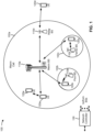
- Fig. 1 is a diagram illustrating a wireless network 100 in which aspects of the present disclosure may be practiced.
- the wireless network 100 may be an LTE network or some other wireless network, such as a 5G or NR network.
- the wireless network 100 may include a number of BSs 110 (shown as BS 110a, BS 110b, BS 110c, and BS 110d) and other network entities.
- a BS is an entity that communicates with user equipment (UEs) and may also be referred to as a base station, a NR BS, a Node B, a gNB, a 5G node B (NB), an access point, a transmit receive point (TRP), and/or the like.
- Each BS may provide communication coverage for a particular geographic area.
- the term "cell" can refer to a coverage area of a BS and/or a BS subsystem serving this coverage area, depending on the context in which the term is used.
- a BS may provide communication coverage for a macro cell, a pico cell, a femto cell, and/or another type of cell.
- a macro cell may cover a relatively large geographic area (e.g., several kilometers in radius) and may allow unrestricted access by UEs with service subscription.
- a pico cell may cover a relatively small geographic area and may allow unrestricted access by UEs with service subscription.
- a femto cell may cover a relatively small geographic area (e.g., a home) and may allow restricted access by UEs having association with the femto cell (e.g., UEs in a closed subscriber group (CSG)).
- a BS for a macro cell may be referred to as a macro BS.
- a BS for a pico cell may be referred to as a pico BS.
- a BS for a femto cell may be referred to as a femto BS or a home BS.
- a BS 110a may be a macro BS for a macro cell 102a
- a BS 110b may be a pico BS for a pico cell 102b
- a BS 110c may be a femto BS for a femto cell 102c.
- a BS may support one or multiple (e.g., three) cells.
- the terms "eNB”, “base station”, “NR BS”, “gNB”, “TRP”, “AP”, “node B", “5G NB”, and “cell” may be used interchangeably herein.
- a cell may not necessarily be stationary, and the geographic area of the cell may move according to the location of a mobile BS.
- the BSs may be interconnected to one another and/or to one or more other BSs or network nodes (not shown) in the wireless network 100 through various types of backhaul interfaces such as a direct physical connection, a virtual network, and/or the like using any suitable transport network.
- Wireless network 100 may also include relay stations.
- a relay station is an entity that can receive a transmission of data from an upstream station (e.g., a BS or a UE) and send a transmission of the data to a downstream station (e.g., a UE or a BS).
- a relay station may also be a UE that can relay transmissions for other UEs.
- a relay BS 110d may communicate with macro BS 110a and a UE 120d in order to facilitate communication between BS 110a and UE 120d.
- a relay BS may also be referred to as a relay station, a relay base station, a relay, etc.
- Wireless network 100 may be a heterogeneous network that includes BSs of different types, e.g., macro BSs, pico BSs, femto BSs, relay BSs, etc. These different types of BSs may have different transmit power levels, different coverage areas, and different impacts on interference in wireless network 100.
- macro BSs may have a high transmit power level (e.g., 5 to 40 Watts) whereas pico BSs, femto BSs, and relay BSs may have lower transmit power levels (e.g., 0.1 to 2 Watts).
- a network controller 130 may couple to a set of BSs and may provide coordination and control for these BSs.
- Network controller 130 may communicate with the BSs via a backhaul.
- the BSs may also communicate with one another, e.g., directly or indirectly via a wireless or wireline backhaul.
- UEs 120 may be dispersed throughout wireless network 100, and each UE may be stationary or mobile.
- a UE may also be referred to as an access terminal, a terminal, a mobile station, a subscriber unit, a station, etc.
- a UE may be a cellular phone (e.g., a smart phone), a personal digital assistant (PDA), a wireless modem, a wireless communication device, a handheld device, a laptop computer, a cordless phone, a wireless local loop (WLL) station, a tablet, a camera, a gaming device, a netbook, a smartbook, an ultrabook, a medical device or equipment, biometric sensors/devices, wearable devices (smart watches, smart clothing, smart glasses, smart wrist bands, smart jewelry (e.g., smart ring, smart bracelet)), an entertainment device (e.g., a music or video device, or a satellite radio), a vehicular component or sensor, smart meters/sensors, industrial manufacturing equipment, a global positioning system device, or any other suitable device that is configured to communicate via a wireless or wired medium.
- a cellular phone e.g., a smart phone
- PDA personal digital assistant
- WLL wireless local loop
- MTC and eMTC UEs include, for example, robots, drones, remote devices, sensors, meters, monitors, location tags, etc., that may communicate with a base station, another device (e.g., remote device), or some other entity.
- a wireless node may provide, for example, connectivity for or to a network (e.g., a wide area network such as Internet or a cellular network) via a wired or wireless communication link.
- Some UEs may be considered Internet-of Things (IoT) devices, and/or may be implemented as may be implemented as NB-IoT (narrowband internet of things) devices.
- Some UEs may be considered a Customer Premises Equipment (CPE).
- UE 120 may be included inside a housing that houses components of UE 120, such as processor components, memory components, and/or the like.
- any number of wireless networks may be deployed in a given geographic area.
- Each wireless network may support a particular RAT and may operate on one or more frequencies.
- a RAT may also be referred to as a radio technology, an air interface, etc.
- a frequency may also be referred to as a carrier, a frequency channel, etc.
- Each frequency may support a single RAT in a given geographic area in order to avoid interference between wireless networks of different RATs.
- NR or 5G RAT networks may be deployed.
- a scheduling entity e.g., a base station
- the scheduling entity may be responsible for scheduling, assigning, reconfiguring, and releasing resources for one or more subordinate entities. That is, for scheduled communication, subordinate entities utilize resources allocated by the scheduling entity.
- Base stations are not the only entities that may function as a scheduling entity. That is, in some examples, a UE may function as a scheduling entity, scheduling resources for one or more subordinate entities (e.g., one or more other UEs). In this example, the UE is functioning as a scheduling entity, and other UEs utilize resources scheduled by the UE for wireless communication.
- a UE may function as a scheduling entity in a peer-to-peer (P2P) network, and/or in a mesh network. In a mesh network example, UEs may optionally communicate directly with one another in addition to communicating with the scheduling entity.
- P2P peer-to-peer
- mesh network UEs may optionally communicate directly with one another in addition to communicating with the scheduling entity.
- a scheduling entity and one or more subordinate entities may communicate utilizing the scheduled resources.
- two or more UEs 120 may communicate directly using one or more sidelink channels (e.g., without using a base station 110 as an intermediary to communicate with one another).
- the UEs 120 may communicate using peer-to-peer (P2P) communications, device-to-device (D2D) communications, a vehicle-to-everything (V2X) protocol (e.g., which may include a vehicle-to-vehicle (V2V) protocol, a vehicle-to-infrastructure (V2I) protocol, and/or the like), a mesh network, and/or the like).
- V2X vehicle-to-everything
- the UE 120 may perform scheduling operations, resource selection operations, and/or other operations described elsewhere herein as being performed by the base station 110.
- Fig. 1 is provided merely as an example. Other examples may differ from what is described with regard to Fig. 1 .
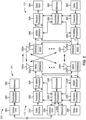
- Fig. 2 shows a block diagram of a design 200 of base station 110 and UE 120, which may be one of the base stations and one of the UEs in Fig. 1 .
- Base station 110 may be equipped with T antennas 234a through 234t
- UE 120 may be equipped with R antennas 252a through 252r, where in general T ⁇ 1 and R ⁇ 1.
- a transmit processor 220 may receive data from a data source 212 for one or more UEs, select one or more modulation and coding schemes (MCS) for each UE based at least in part on channel quality indicators (CQIs) received from the UE, process (e.g., encode and modulate) the data for each UE based at least in part on the MCS(s) selected for the UE, and provide data symbols for all UEs. Transmit processor 220 may also process system information (e.g., for semi-static resource partitioning information (SRPI), etc.) and control information (e.g., CQI requests, grants, upper layer signaling, etc.) and provide overhead symbols and control symbols.
- MCS modulation and coding schemes
- CQIs channel quality indicators
- Transmit processor 220 may also process system information (e.g., for semi-static resource partitioning information (SRPI), etc.) and control information (e.g., CQI requests, grants, upper layer signaling, etc.) and provide overhead symbols
- Transmit processor 220 may also generate reference symbols for reference signals (e.g., the cell-specific reference signal (CRS)) and synchronization signals (e.g., the primary synchronization signal (PSS) and secondary synchronization signal (SSS)).
- a transmit (TX) multiple-input multiple-output (MIMO) processor 230 may perform spatial processing (e.g., precoding) on the data symbols, the control symbols, the overhead symbols, and/or the reference symbols, if applicable, and may provide T output symbol streams to T modulators (MODs) 232a through 232t. Each modulator 232 may process a respective output symbol stream (e.g., for OFDM, etc.) to obtain an output sample stream.
- T modulators modulators
- Each modulator 232 may further process (e.g., convert to analog, amplify, filter, and upconvert) the output sample stream to obtain a downlink signal.
- T downlink signals from modulators 232a through 232t may be transmitted via T antennas 234a through 234t, respectively.
- the synchronization signals can be generated with location encoding to convey additional information.
- antennas 252a through 252r may receive the downlink signals from base station 110 and/or other base stations and may provide received signals to demodulators (DEMODs) 254a through 254r, respectively.
- Each demodulator 254 may condition (e.g., filter, amplify, downconvert, and digitize) a received signal to obtain input samples.
- Each demodulator 254 may further process the input samples (e.g., for OFDM, etc.) to obtain received symbols.
- a MIMO detector 256 may obtain received symbols from all R demodulators 254a through 254r, perform MIMO detection on the received symbols if applicable, and provide detected symbols.
- a receive processor 258 may process (e.g., demodulate and decode) the detected symbols, provide decoded data for UE 120 to a data sink 260, and provide decoded control information and system information to a controller/processor 280.
- a channel processor may determine reference signal received power (RSRP), received signal strength indicator (RSSI), reference signal received quality (RSRQ), channel quality indicator (CQI), etc.
- RSRP reference signal received power
- RSSI received signal strength indicator
- RSRQ reference signal received quality
- CQI channel quality indicator
- one or more components of UE 120 may be included in a housing.
- a transmit processor 264 may receive and process data from a data source 262 and control information (e.g., for reports comprising RSRP, RSSI, RSRQ, CQI, etc.) from controller/processor 280. Transmit processor 264 may also generate reference symbols for one or more reference signals. The symbols from transmit processor 264 may be precoded by a TX MIMO processor 266 if applicable, further processed by modulators 254a through 254r (e.g., for DFT-s-OFDM, CP-OFDM, etc.), and transmitted to base station 110.
- control information e.g., for reports comprising RSRP, RSSI, RSRQ, CQI, etc.
- Transmit processor 264 may also generate reference symbols for one or more reference signals.
- the symbols from transmit processor 264 may be precoded by a TX MIMO processor 266 if applicable, further processed by modulators 254a through 254r (e.g., for DFT-s-OFDM, CP-
- the uplink signals from UE 120 and other UEs may be received by antennas 234, processed by demodulators 232, detected by a MIMO detector 236 if applicable, and further processed by a receive processor 238 to obtain decoded data and control information sent by UE 120.
- Receive processor 238 may provide the decoded data to a data sink 239 and the decoded control information to controller/processor 240.
- Base station 110 may include communication unit 244 and communicate to network controller 130 via communication unit 244.
- Network controller 130 may include communication unit 294, controller/processor 290, and memory 292.
- Controller/processor 240 of base station 110, controller/processor 280 of UE 120, and/or any other component(s) of Fig. 2 may perform one or more techniques associated with deriving channel state information (CSI) using a subset of configured CSI reference signal (CSI-RS) resources, as described in more detail elsewhere herein.
- controller/processor 240 of base station 110, controller/processor 280 of UE 120, and/or any other component(s) of Fig. 2 may perform or direct operations of, for example, process 800 of Fig. 8 and/or other processes as described herein.
- Memories 242 and 282 may store data and program codes for base station 110 and UE 120, respectively.
- a scheduler 246 may schedule UEs for data transmission on the downlink and/or uplink.
- the stored program codes when executed by processor 280 and/or other processors and modules at UE 120, may cause the UE 120 to perform operations described with respect to process 800 of Fig. 8 and/or other processes as described herein.
- a scheduler 246 may schedule UEs for data transmission on the downlink and/or uplink.
- UE 120 may include means for receiving a configuration that indicates a set of channel state information reference signals (CSI-RSs) to be measured by the UE for deriving channel state information (CSI), one or more time domain resources (e.g., one or more slots) for which the UE is to derive the CSI, and a time domain resource (e.g., a slot) for transmission of a CSI report that includes the CSI, wherein the one or more time domain resources (e.g., the one or more slots) for which the UE is to derive the CSI occur after the time domain resource (e.g., the slot) for transmission of the CSI report; means for determining that the UE cannot measure a first subset of CSI-RSs included in the set of CSI-RSs; means for deriving one or more parameters for the CSI report based at least in part on measuring a second subset of CSI-RSs included in the set of CSI-RSs, wherein the second subset of CSI-RSs excludes
- While blocks in Fig. 2 are illustrated as distinct components, the functions described above with respect to the blocks may be implemented in a single hardware, software, or combination component or in various combinations of components.
- the functions described with respect to the transmit processor 264, the receive processor 258, and/or the TX MIMO processor 266 may be performed by or under the control of processor 280.
- Fig. 2 is provided merely as an example. Other examples may differ from what is described with regard to Fig. 2 .
- Fig. 3 is a diagram illustrating an example 300 of CSI reporting, in accordance with various aspects of the present disclosure.
- a UE may measure one or more CSI-RSs transmitted by a base station at a first time n 1 (e.g., in a first slot or time domain resource), the UE may transmit a CSI report to the base station based at least in part on those measurements at a second time n 2 (e.g., in a second slot or time domain resource) after processing the one or more CSI-RSs, and the base station may transmit data to the UE based at least in part on the CSI report at a third time n 3 (e.g., in a third slot or time domain resource).
- the CSI-RS measurements at time n 1 may indicate channel conditions at time n 1 .
- the channel conditions at time n 3 when the base station transmits data based at least in part on the CSI report of the CSI-RS measurements, may be different from the channel conditions at time n 1 . This may be referred to as channel aging.
- the base station may select sub-optimal transmission parameters for transmission of the data at time n 3 .
- Such transmission parameters may include, for example, a modulation and coding scheme (MCS), a rank, a precoder, a beam, a multiple input multiple output (MIMO) layer, and/or the like. This may result in a missed communication if channel conditions have degraded between time n 1 and time n 3 , or may result in under-utilization of network resources if channel conditions have improved between time n 1 and time n 3 .
- MCS modulation and coding scheme
- MIMO multiple input multiple output
- a UE may transmit a CSI report in a CSI reporting slot n' .
- the CSI report may be based at least in part on a CSI reference resource that occurs in a slot prior to transmission of the CSI report.
- the CSI reference resource for CSI reporting in uplink slot n' may be defined by a downlink slot n - n CSI_ref , as shown, where n depends on n' and the subcarrier spacing configurations for downlink and uplink, and where n CSI_ref is a valid downlink slot that depends on various factors such as whether CSI reporting is periodic, aperiodic, or semi-persistent.
- the UE uses one or more CSI-RSs that are received no later than the CSI reference resource (e.g., that are received in or before the CSI reference resource) to derive parameters for the CSI report.
- the CSI report represents channel conditions in or prior to the CSI reference resource.
- the CSI report is outdated, and a subsequent data transmission by a base station that occurs after the CSI report is configured according to outdated channel conditions, as described above.
- a UE may extrapolate (e.g., estimate, derive, and/or the like) future channel conditions using a set of CSI-RSs that occur prior to the CSI reference resource, as described in more detail below in connection with Fig. 4 .
- This may be referred to as extrapolation-based CSI reporting, an extrapolated CSI report, and/or the like.
- the base station may select better transmission parameters for a data transmission as compared to using outdated CSI.
- Fig. 3 is provided merely as an example. Other examples may differ from what is described with regard to Fig. 3 .
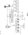
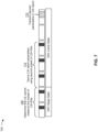
- Fig. 4 is a diagram illustrating an example 400 of extrapolation-based CSI reporting, in accordance with various aspects of the present disclosure. As shown in Fig. 4 , a UE 120 and a base station 110 may communicate with one another.
- the base station 110 may transmit, to the UE 120, a configuration for CSI reporting.
- the configuration may be for an extrapolated CSI report, where the UE 120 uses a set of CSI-RSs to derive CSI parameters for one or more slots that occur later in time than the set of CSI-RSs and/or that occur later in time than the slot used to transmit the CSI report.
- the configuration may be indicated in a radio resource control (RRC) message, such as an RRC configuration message, an RRC reconfiguration message, and/or the like.
- RRC radio resource control
- CSI-IM CSI for interference management
- the configuration may indicate a set of CSI-RSs to be measured by the UE 120 to derive CSI.
- the set of CSI-RSs may occur in a set of CSI-RS resources within a CSI reference resource interval.
- the CSI reference resource interval may include multiple transmission time intervals (TTIs) (e.g., slots or other time domain resources).
- TTIs transmission time intervals
- the CSI reference resource interval may span a number of slots starting with a slot shown as n - n CSI_ref - n CSI_span and ending with a slot shown as n - n CSI_ref .
- the slot n - n CSI_ref is described above in connection with Fig.
- the slot n - n CSI_ref - n CSI_span may occur n CSI_span slots before the slot n - n CSI_ref , where n CSI_span represents the length of the CSI reference resource interval.
- the CSI reference resource interval is five slots in length.
- the set of CSI-RSs to be measured by the UE 120 spans across multiple non-adjacent symbols associated with a single CSI-RS transmission occasion.
- the UE 120 may be configured with a single CSI-RS resource that includes multiple symbols (e.g., non-adjacent symbols). The non-adjacent symbols may occur in the CSI reference resource interval, as shown.
- the set of CSI-RSs to be measured by the UE 120 includes multiple one-symbol CSI-RS transmission occasions that occur in non-adjacent symbols.
- the UE 120 may be configured with multiple CSI-RS resources (e.g., multiple CSI-RS transmission occasions) that each occur within a single symbol.
- the symbols may be non-adjacent and may occur in the CSI reference resource interval, as shown.
- the UE 120 may be configured with a single CSI-RS that includes five non-adjacent symbols, or may be configured with five CSI-RS resources that occur in non-adjacent symbols.
- the configuration may indicate one or more slots for which the UE 120 is to derive the CSI, shown as CSI reference report slots. As shown, these slots occur after the CSI reference resource interval (e.g., after the set of CSI-RSs to be measured by the UE 120) and after the slot in which the CSI report is transmitted. In example 400, there are four CSI reference report slots, and the UE 120 uses the CSI-RSs measured in the CSI reference resource interval to extrapolate and/or derive CSI parameters for the four CSI reference report slots.
- the configuration may indicate a slot for transmission of a CSI report that includes the CSI.
- this slot is shown as slot n' , and is described above in connection with Fig. 3 .
- the UE 120 may be configured with and/or may determine an offset (e.g., a slot offset, a symbol offset, and/or the like) between the CSI reference resource interval and a CSI reference report.
- the offset may represent an offset between the latest-occurring CSI-RS (e.g., within the CSI reference resource interval) and the earliest-occurring CSI reference report slot for which CSI parameters are to be derived using the set of CSI-RSs.
- the UE 120 may extrapolate (e.g., estimate, derive, and/or the like) future channel conditions using a set of CSI-RSs that occur in the CSI reference resource interval. For example, the UE 120 may use the set of CSI-RSs in the CSI reference resource interval to extrapolate CSI parameters for the CSI reference report slots (e.g., by measuring a change in channel conditions over time). The UE 120 may report the extrapolated CSI parameters in the CSI report.
- Example CSI parameters include a channel quality indicator (CQI) parameter, a precoding matrix indicator (PMI) parameter, a CSI-RS resource indicator (CRI) parameter, a strongest layer indication (SLI) parameter, a rank indication (RI) parameter, a layer 1 (L1) reference signal received power (RSRP) (L1-RSRP) parameter, a layer 1 (L1) signal-to-interference-plus-noise ratio (SINR) (L1-SINR) parameter, and/or the like.
- CQI channel quality indicator
- PMI precoding matrix indicator
- CRI CSI-RS resource indicator
- SLI strongest layer indication
- RI rank indication
- RSRP reference signal received power
- SINR layer 1
- L1-SINR layer 1
- the base station 110 may select better transmission parameters for a data transmission as compared to using outdated CSI.
- the UE 120 may not be able to measure all of the configured CSI-RSs and/or may not be able to use all of the configured CSI-RSs to derive CSI parameters for the CSI reference report slots.
- a CSI-RS may occur too late in time as compared to a corresponding CSI reference report slot (e.g., may occur with too small an offset) to permit the UE 120 to process the CSI-RS.
- the UE 120 may not be able to measure all of the configured CSI-RSs due to being in a discontinuous reception (DRX) sleep state during the CSI reference resource interval, performing a bandwidth part (BWP) switch during the CSI reference resource interval, undergoing serving cell activation during the CSI reference resource interval, receiving a reconfiguration of a CSI report, receiving an indication to activate CSI reporting (e.g., semi-persistent CSI reporting and/or the like), reconfiguration of a CSI-RS slot to an uplink slot, and/or the like.
- DRX discontinuous reception
- BWP bandwidth part
- the UE 120 may be configured to drop the CSI report (e.g., by refraining from transmitting the CSI report). However, if the UE 120 is able to measure a subset of the configured CSI-RSs, then dropping the CSI report may lead to sub-optimal selection of transmission parameters by the base station 110 as compared to extrapolating CSI parameters using a subset of the configured CSI-RSs. Some techniques and apparatuses described herein improve selection of transmission parameters by the base station 110 by permitting the UE 120 to extrapolate or derive CSI parameters for a CSI report using a subset of configured CSI-RSs in a CSI reference resource interval.
- Fig. 4 is provided merely as an example. Other examples may differ from what is described with regard to Fig. 4 .
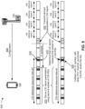
- Fig. 5 is a diagram illustrating an example 500 of deriving CSI using a subset of configured CSI-RS resources, in accordance with various aspects of the present disclosure.
- a UE 120 and a base station 110 may communicate with one another.
- the base station 110 may transmit, to the UE 120, a configuration for CSI reporting, as described above in connection with Fig. 4 .
- the configuration may be for an extrapolated CSI report, where the UE 120 uses a set of CSI-RSs to derive CSI parameters for one or more slots that occur later in time than the set of CSI-RSs and/or that occur later in time than the slot used to transmit the CSI report.
- the configuration may be indicated in an RRC message, such as an RRC configuration message, an RRC reconfiguration message, and/or the like. As described above in connection with Fig.
- the configuration may indicate a set of CSI-RSs to be measured by the UE 120 (e.g., in a CSI reference resource interval) for deriving CSI, one or more slots (e.g., one or more CSI reference report slots) for which the UE 120 is to derive the CSI, and a slot for transmission of a CSI report that includes the CSI.
- the one or more slots for which the UE 120 is to derive the CSI may occur after the slot for transmission of the CSI report.
- some techniques are described herein in connection with slots, these techniques may be applied for other time domain resources, such as subframes, mini-slots, symbols, sets of symbols, and/or the like, which may be consecutive or non-consecutive.
- the UE 120 may determine that the UE 120 cannot measure a first subset of CSI-RSs (e.g., one or more CSI-RSs) included in the configured set of CSI-RSs. For example, the UE 120 may be unable to measure the first subset of CSI-RSs due to a timing of the first subset of CSI-RSs relative to the slot for transmission of the CSI report. For example, the UE 120 may be unable to measure the first subset of CSI-RSs because the first subset of CSI-RSs occurs too late in time to be included in the CSI report.
- a first subset of CSI-RSs e.g., one or more CSI-RSs
- the UE 120 may not be expected to measure a CSI-RS if the last symbol (e.g., OFDM symbol) of the CSI-RS is received less than a threshold number of symbols (shown as Z' symbols) before a transmission time of the first symbol (e.g., the first OFDM symbol) of the CSI report.
- a threshold number of symbols shown as Z' symbols
- Z' symbols a threshold number of symbols
- the UE 120 cannot use this CSI-RS to determine a CSI parameter to be included in the CSI report (e.g., due to insufficient processing time).
- the UE 120 may be unable to measure the first subset of CSI-RSs because a set of symbols in which the first subset of CSI-RSs occurs are reconfigured to uplink symbols and/or are otherwise modified such that the CSI-RSs do not occur in the set of symbols or transmission of the CSI-RSs in the set of symbols would result in a collision with another communication.
- a CSI-RS symbol may be reconfigured to an uplink symbol (e.g., causing an uplink collision), may be reconfigured to carry transmissions for another physical (PHY) channel, may be punctured, and/or the like.
- the UE 120 may not be able to measure the first subset of CSI-RSs because the UE 120 is undergoing a BWP switch when the first subset of CSI-RSs occurs, as described in more detail below in connection with Fig. 6 . Additionally, or alternatively, the UE 120 may not be able to measure the first subset of CSI-RSs because the UE 120 is in a DRX sleep state when the first subset of CSI-RSs occurs, as described in more detail below in connection with Fig. 7 .
- the UE 120 may not be able to measure the first subset of CSI-RSs because the UE 120 is undergoing serving cell activation when the first subset of CSI-RSs occurs, because the UE 120 has received a configuration or a reconfiguration of a CSI report after the first subset of CSI-RSs occurs, because the UE 120 has received an indication to activate CSI reporting (e.g., semi-persistent CSI reporting and/or the like) after the first subset of CSI-RSs occur, and/or the like.
- CSI reporting e.g., semi-persistent CSI reporting and/or the like
- the UE 120 may derive one or more parameters for the CSI report (e.g., one or more CSI parameters) based at least in part on measuring a second subset of CSI-RSs included in the set of CSI-RSs.
- the second subset of CSI-RSs measured by the UE 120 excludes the first subset of CSI-RSs that cannot be measured by the UE 120.
- the UE 120 uses the first four out of five configured CSI-RSs to derive the one or more CSI parameters, and excludes the fifth (e.g., latest-occurring) configured CSI-RS from being used for the derivation.
- the UE 120 may derive the one or more parameters for the CSI report based at least in part on a determination that the second subset of CSI-RSs (e.g., capable of being measured by the UE 120 for the extrapolated CSI report) includes a threshold number of CSI-RSs.
- the threshold number may be two or may be at least two because the UE 120 may need to measure at least two CSI-RSs to extrapolate a change in channel conditions over time. Additionally, or alternatively, the threshold number may be based at least in part on a UE capability.
- different UEs 120 may have different capabilities for extrapolating CSI parameters from CSI-RSs, with some UEs 120 requiring fewer CSI-RSs to perform extrapolation and some UEs 120 requiring more CSI-RSs to perform extrapolation.
- the threshold number may be configured for the UE 120 by the base station 110 (e.g., in an RRC message).
- the base station 110 may require a certain degree of accuracy for CSI parameter extrapolation, and the degree of accuracy may depend on the number of CSI-RSs used to perform the extrapolation.
- the configured set of CSI-RSs may span across multiple non-adjacent symbols associated with a single CSI-RS transmission occasion.
- the threshold number may represent a threshold number of non-adjacent symbols (e.g., at least two non-adjacent symbols that each carry a CSI-RS).
- the threshold number may represent a minimum number of OFDM symbols (e.g., non-adjacent or non-consecutive OFDM symbols) that include CSI-RSs.
- the UE 120 may determine that the threshold number is satisfied if the second set of CSI-RSs includes CSI-RSs in the threshold number of non-adjacent symbols.
- the configured set of CSI-RSs may include multiple one-symbol CSI-RS transmission occasions that occur in non-adjacent symbols.
- the threshold number may represent a threshold number of one-symbol CSI-RS transmission occasions (e.g., at least two one-symbol CSI-RS transmission occasions).
- the threshold number may represent a minimum number of CSI-RS resources.
- the UE 120 may determine that the threshold number is satisfied if the second set of CSI-RSs includes CSI-RSs in the threshold number of one-symbol CSI-RS transmission occasions.
- the UE 120 may transmit the CSI report, including the one or more CSI parameters, in the slot for transmission of the CSI report.
- the UE 120 may transmit the CSI report based at least in part on a determination that the second subset of CSI-RSs include a threshold number of CSI-RSs, in a similar manner as described above. In this case, if the second subset of CSI-RSs includes the threshold number of CSI-RSs, then the UE 120 may transmit the CSI report. Conversely, if the second subset of CSI-RSs does not include the threshold number of CSI-RSs, then the UE 120 may drop the CSI report (e.g., may refrain from transmitting the CSI report).
- the UE 120 may refrain from updating the CSI report (e.g., may transmit a dummy CSI report or a default CSI report, may retransmit a most recently transmitted CSI report, may transmit CSI parameters from the most recently transmitted CSI report, and/or the like).
- the UE 120 may be able to improve selection of transmission parameters by the base station 110.
- Fig. 5 is provided merely as an example. Other examples may differ from what is described with regard to Fig. 5 .
- Fig. 6 is a diagram illustrating an example 600 of deriving CSI using a subset of configured CSI-RS resources, in accordance with various aspects of the present disclosure.
- a UE 120 may determine that the UE 120 cannot measure a first subset of CSI-RSs included in a configured set of CSI-RSs, as described above in connection with Fig. 5 .
- the UE 120 is undergoing BWP switching (e.g., a BWP change) during the CSI reference resource interval (e.g., during a portion of the CSI reference resource interval).
- BWP switching e.g., a BWP change
- the UE 120 cannot measure the first two CSI-RSs of a set of five CSI-RSs configured for a BWP to which the UE 120 switches.
- the UE 120 determines that the UE 120 cannot measure the first subset of CSI-RSs based at least in part on detecting the change in BWP. However, in some aspects, the UE 120 may determine that the UE 120 cannot measure the first subset of CSI-RSs based at least in part on detecting a CSI report configuration, a CSI report reconfiguration, a serving cell activation, an activation of CSI (e.g., semi-persistent CSI), and/or the like.
- a CSI report configuration e.g., a CSI report reconfiguration
- a serving cell activation e.g., an activation of CSI (e.g., semi-persistent CSI), and/or the like.
- the UE 120 may derive one or more CSI parameters for the CSI report based at least in part on measuring a second subset of CSI-RSs included in the configured set of CSI-RSs, in a similar manner as described above in connection with Fig. 5 .
- the UE 120 completes the BWP switch and measures the last three CSI-RSs of the set of five CSI-RSs configured for the BWP to which the UE 120 switches.
- the UE 120 may transmit the CSI report, including the one or more derived CSI parameters, in a slot for transmission of the CSI report, in a similar manner as described above in connection with Fig. 5 .
- the UE 120 may transmit the CSI report based at least in part on a determination that the second subset of CSI-RSs include a threshold number of CSI-RSs (e.g., at least two CSI-RSs, at least three CSI-RSs, or the like), in a similar manner as described above.
- the UE 120 may transmit the CSI report based at least in part on a determination that the second subset of CSI-RSs includes a threshold number of CSI-RSs that are received within a CSI reference resource interval associated with the CSI report (e.g., at least Z' symbols before transmission of the CSI report). In this way, the UE 120 may be able to improve selection of transmission parameters by the base station 110.
- Fig. 6 is provided merely as an example. Other examples may differ from what is described with regard to Fig. 6 .
- Fig. 7 is a diagram illustrating an example 700 of deriving CSI using a subset of configured CSI-RS resources, in accordance with various aspects of the present disclosure.
- a UE 120 may determine that the UE 120 cannot measure a first subset of CSI-RSs included in a configured set of CSI-RSs, as described above in connection with Fig. 5 .
- the UE 120 is in a DRX sleep state during the CSI reference resource interval (e.g., during a portion of the CSI reference resource interval).
- the UE 120 cannot measure the first two CSI-RSs of a set of five CSI-RSs configured for the UE 120.
- the UE 120 may derive one or more CSI parameters for the CSI report based at least in part on measuring a second subset of CSI-RSs included in the configured set of CSI-RSs, in a similar manner as described above in connection with Fig. 5 .
- the UE 120 exits the DRX sleep state, enters a DRX active state, and measures the last three CSI-RSs of the set of five CSI-RSs during the DRX active state.
- the UE 120 may transmit the CSI report, including the one or more derived CSI parameters, in a slot for transmission of the CSI report, in a similar manner as described above in connection with Fig. 5 .
- the UE 120 may transmit the CSI report based at least in part on a determination that the second subset of CSI-RSs include a threshold number of CSI-RSs (e.g., at least two CSI-RSs, at least three CSI-RSs, or the like), in a similar manner as described above.
- the UE 120 may transmit the CSI report based at least in part on a determination that the second subset of CSI-RSs includes a threshold number of CSI-RSs that are received during a DRX active time within a CSI reference resource interval associated with the CSI report (e.g., at least Z' symbols before transmission of the CSI report). In this way, the UE 120 may be able to improve selection of transmission parameters by the base station 110.
- the UE 120 may transmit the CSI report based at least in part on a determination that the second subset of CSI-RSs includes a threshold number of latest-occurring CSI-RSs (e.g., of the configured set of CSI-RSs) that occur during a DRX active time. For example, if the UE 120 is in the DRX active state for a set of earlier-occurring CSI-RSs of the configured set of CSI-RSs and then enters the DRX sleep state for a set of later-occurring CSI-RSs of the configured set of CSI-RSs, then the UE 120 may refrain from transmitting the CSI report.
- a threshold number of latest-occurring CSI-RSs e.g., of the configured set of CSI-RSs
- the UE 120 may be in the DRX sleep state during scheduled transmission of the CSI report and/or may not have the latest channel information (as indicated by the later-occurring CSI-RSs), and so may drop the CSI report. In this case, the UE 120 may refrain from measuring the earlier-occurring CSI-RSs to conserve UE resources (e.g., processing resources, memory resources, battery power, and/or the like).
- UE resources e.g., processing resources, memory resources, battery power, and/or the like.
- Fig. 7 is provided merely as an example. Other examples may differ from what is described with regard to Fig. 7 .
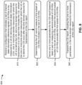
- Fig. 8 is a diagram illustrating an example process 800 performed, for example, by a UE, in accordance with various aspects of the present disclosure.
- Example process 800 is an example where the UE (e.g., UE 120 and/or the like) performs operations associated with deriving CSI using a subset of configured CSI-RS resources.
- the UE e.g., UE 120 and/or the like
- process 800 may include receiving a configuration that indicates a set of CSI-RSs to be measured by the UE for deriving CSI, one or more time domain resources for which the UE is to derive the CSI, and a time domain resource for transmission of a CSI report that includes the CSI, wherein the one or more time domain resources for which the UE is to derive the CSI occur after the time domain resource for transmission of the CSI report (block 810).
- the UE may receive a configuration that indicates a set of CSI-RSs to be measured by the UE for deriving CSI, one or more time domain resources for which the UE is to derive the CSI, and a time domain resource for transmission of a CSI report that includes the CSI, as described above.
- the one or more time domain resources for which the UE is to derive the CSI occur after the time domain resource for transmission of the CSI report.
- the one or more time domain resources are one or more slots, one or more mini-slots, one or more symbols, one or more sets of symbols, one or more subframes, or the like.
- the time domain resource for transmission of the CSI report may be a slot, a mini-slot, a symbol, a set of symbols, a subframe, or the like.
- process 800 may include determining that the UE cannot measure a first subset of CSI-RSs included in the set of CSI-RSs (block 820).
- the UE e.g., using receive processor 258, transmit processor 264, controller/processor 280, memory 282, and/or the like
- process 800 may include deriving one or more parameters for the CSI report based at least in part on measuring a second subset of CSI-RSs included in the set of CSI-RSs, wherein the second subset of CSI-RSs excludes the first subset of CSI-RSs (block 830).
- the UE e.g., using receive processor 258, transmit processor 264, controller/processor 280, memory 282, and/or the like
- the second subset of CSI-RSs excludes the first subset of CSI-RSs.
- process 800 may include transmitting the CSI report, including the one or more parameters, in the time domain resource for transmission of the CSI report (block 840).
- the UE e.g., using transmit processor 264, controller/processor 280, memory 282, and/or the like
- process 800 may include additional blocks, fewer blocks, different blocks, or differently arranged blocks than those depicted in Fig. 8 . Additionally, or alternatively, two or more of the blocks of process 800 may be performed in parallel.
- ком ⁇ онент is intended to be broadly construed as hardware, firmware, or a combination of hardware and software.
- a processor is implemented in hardware, firmware, or a combination of hardware and software.
- satisfying a threshold may refer to a value being greater than the threshold, greater than or equal to the threshold, less than the threshold, less than or equal to the threshold, equal to the threshold, not equal to the threshold, and/or the like.
- "at least one of a, b, or c" is intended to cover a, b, c, a-b, a-c, b-c, and a-b-c, as well as any combination with multiples of the same element (e.g., a-a, a-a-a, a-a-b, a-a-c, a-b-b, a-c-c, b-b, b-b-b, b-b-c, c-c, and c-c-c or any other ordering of a, b, and c).
Landscapes
- Engineering & Computer Science (AREA)
- Signal Processing (AREA)
- Computer Networks & Wireless Communication (AREA)
- Power Engineering (AREA)
- Mobile Radio Communication Systems (AREA)
Claims (15)
- Ein Verfahren zur drahtlosen Kommunikation, das von einem Benutzergerät, UE (120), durchgeführt wird, aufweisend:Empfangen (810) einer Konfiguration, die einen Satz von Kanalzustandsinformations-Referenzsignalen, CSI-RSs, angibt, die von dem UE (120) zum Ableiten von Kanalzustandsinformationen, CSI, zu messen sind, eine oder mehrere Zeitbereichsressourcen, für die das UE die CSI ableiten soll, undeine Zeitbereichsressource zur Übertragung eines CSI-Berichts, der die CSI enthält, wobei die eine oder die mehreren Zeitbereichsressourcen, für die die UE die CSI ableiten soll, nach der Zeitbereichsressource zur Übertragung des CSI-Berichts auftreten;Bestimmen (820), dass die UE (120) eine erste Teilmenge von CSI-RSs, die in der Menge von CSI-RSs enthalten ist, nicht messen kann, basierend zumindest teilweise auf zumindest einem von:einer Kollision zwischen zumindest einem CSI-RS der ersten Teilmenge von CSI-RS und einer anderen Kommunikation,einer Konfiguration eines Symbols zumindest eines CSI-RS der ersten Teilmenge von CSI-RS als ein Symbol für eine Aufwärtsverbindung oder eine Punktierens zumindest eines CSI-RS der ersten Teilmenge von CSI-RS;Ableiten (830) eines oder mehrerer Parameter für den CSI-Bericht, zumindest teilweise basierend auf der Messung einer zweiten Teilmenge von CSI-RS, die in der Menge von CSI-RS enthalten ist, wobei die zweite Teilmenge von CSI-RS die erste Teilmenge von CSI-RS ausschließt; undÜbertragen (840) des CSI-Berichts, einschließlich des einen oder der mehreren Parameter, in der Zeitbereichsressource zur Übertragung des CSI-Berichts.
- Das Verfahren nach Anspruch 1, wobei der CSI-Bericht zumindest teilweise auf der Grundlage einer Bestimmung übertragen (840) wird, dass die zweite Teilmenge von CSI-RSs eine Schwellenanzahl von CSI-RSs enthält.
- Das Verfahren nach Anspruch 2, wobei die Schwellenanzahl zumindest teilweise auf der Grundlage einer Fähigkeit des UE (120) basiert.
- Das Verfahren nach Anspruch 2, wobei die Schwellenanzahl zwei beträgt und einen einer minimalen Anzahl von orthogonalen Frequenz gemultiplexten, OFDM, Symbolen, die CSI-RSs enthalten, oder einer minimalen Anzahl von CSI-RS-Ressourcen darstellt.
- Das Verfahren nach Anspruch 1, wobei die Bestimmung, dass das UE (120) die erste Teilmenge von CSI-RSs nicht messen kann, weiter zumindest teilweise auf zumindest einem der folgenden basiert:einer zeitlichen Abstimmung von zumindest einem CSI-RS der ersten Teilmenge von CSI-RSs relativ zu der Zeitbereichsressource für die Übertragung des CSI-Berichts,einer Konfiguration oder Neukonfiguration des CSI-Berichts,einer Aktivierung einer bedienenden Zelle,eine Änderung im Bandbreitenteil,Aktivierung von semi-persistentem CSI,einen diskontinuierlichen Empfang, DRX, Zykluskonfiguration odereine Kombination davon.
- Das Verfahren nach Anspruch 1, wobei die Menge von CSI-RS, die durch die UE (120) zum Ableiten von CSI zu messen ist, sich über mehrere nicht benachbarte Symbole erstreckt, die mit einem einzelnen CSI-RS-Übertragungsanlass verbunden sind.
- Das Verfahren nach Anspruch 1, wobei die Menge von CSI-RS, die durch das UE zum Ableiten von CSI zu messen ist, mehrere CSI-RS-Übertragungsanlässe mit einem Symbol aufweist, die in nicht benachbarten Symbolen auftreten.
- Das Verfahren nach Anspruch 1, weiter aufweisend:Erkennen von zumindest einem von einer CSI-Berichtkonfiguration, einer CSI-Berichtsumkonfiguration, einer Aktivierung einer bedienenden Zelle, einer Bandbreitenteiländerung oder einer Aktivierung von semi-persistentem CSI; undÜbertragen des CSI-Berichts zumindest teilweise basierend auf der Erkennung und weiter zumindest teilweise basierend auf einer Bestimmung, dass die zweite Teilmenge von CSI-RSs eine Schwellenanzahl von CSI-RSs enthält, die innerhalb eines CSI-Referenzressourcenintervalls empfangen werden, das mit dem CSI-Bericht verbunden ist.
- Das Verfahren nach Anspruch 1, wobei der CSI-Bericht zumindest teilweise auf der Grundlage einer Bestimmung übertragen wird, dass die zweite Teilmenge von CSI-RSs eine Schwellenanzahl von CSI-RSs enthält, die während einer aktiven Zeit des diskontinuierlichen Empfangs, DRX, innerhalb eines CSI-Referenzressourcenintervalls empfangen werden, das mit dem CSI-Bericht verbunden ist.
- Das Verfahren nach Anspruch 1, wobei der CSI-Bericht zumindest teilweise auf der Grundlage einer Bestimmung übertragen wird, dass die zweite Teilmenge von CSI-RSs eine Schwellenanzahl von zuletzt auftretenden CSI-RSs enthält, die während einer aktiven Zeit des diskontinuierlichen Empfangs, DRX, auftreten.
- Ein computerlesbares Medium, das eine oder mehrere Anweisungen für die drahtlose Kommunikation speichert, die, wenn sie von einem oder mehreren Prozessoren eines Benutzergeräts, UE (120), ausgeführt werden, bewirken, dass das UE (120) ein Verfahren gemäß einem der Ansprüche 1 bis 10 ausführt, wenn es ausgeführt wird.
- Ein Benutzergerät UE (120) für drahtlose Kommunikation, aufweisend:Mittel zum Empfangen einer Konfiguration, die einen Satz von Kanalzustandsinformations-Referenzsignalen CSI-RS angibt, die durch das UE (120) zu messen sind, um Kanalzustandsinformationen, CSI, abzuleiten, eine oder mehrere Zeitbereichsressourcen, für die das UE (120) die CSI ableiten soll,und eine Zeitbereichsressource zur Übertragung eines CSI-Berichts, der die CSI enthält, wobei die eine oder die mehreren Zeitbereichsressourcen, für die das UE (120) die CSI ableiten soll, nach der Zeitbereichsressource zur Übertragung des CSI-Berichts auftreten;Mittel zum Bestimmen, dass das UE (120) eine erste Teilmenge von CSI-RSs,die in der Menge von CSI-RSs enthalten sind, nicht messen kann, basierend zumindest teilweise auf zumindest einem von:einer Kollision zwischen zumindest einem CSI-RS der ersten Teilmenge von CSI-RS und einer anderen Kommunikation,einer Konfiguration eines Symbols zumindest eines CSI-RS der ersten Teilmenge von CSI-RS als ein Symbol für eine Aufwärtsverbindung oder einer Punktierung zumindest eines CSI-RS der ersten Teilmenge von CSI-RS;Mittel zum Ableiten eines oder mehrerer Parameter für den CSI-Bericht, die zumindest teilweise auf der Messung einer zweiten Teilmenge von CSI-RSs basieren, die in der Menge von CSI-RSs enthalten ist, wobei die zweite Teilmenge von CSI-RSs die erste Teilmenge von CSI-RSs ausschließt; undMittel zum Übertragen des CSI-Berichts, einschließlich des einen oder der mehreren Parameter, in der Zeitbereichsressource zur Übertragung des CSI-Berichts.
- Das Benutzergerät UE (120) zur drahtlosen Kommunikation nach Anspruch 12, wobei der CSI-Bericht zumindest teilweise auf der Grundlage einer Bestimmung übertragen (840) wird, dass die zweite Teilmenge von CSI-RSs eine Schwellenanzahl von CSI-RSs enthält.
- Das Benutzergerät UE (120) zur drahtlosen Kommunikation nach Anspruch 13, wobei die Schwellenanzahl zumindest teilweise auf einer Fähigkeit des UE (120) basiert.
- Das Benutzergerät UE (120) zur drahtlosen Kommunikation nach Anspruch 12, weiter aufweisend:Mittel zum Erfassen zumindest eines von einer CSI-Berichtskonfiguration, einer CSI-Berichtsumkonfiguration, einer Aktivierung einer bedienenden Zelle, einer Bandbreitenteiländerung oder einer Aktivierung von semi-persistentem CSI; undMittel zum Übertragen des CSI-Berichts, der zumindest teilweise auf der Erkennung basiert und weiter zumindest teilweise auf einer Bestimmung basiert, dass die zweite Teilmenge von CSI-RSs eine Schwellenanzahl von CSI-RSs enthält, die innerhalb eines CSI-Referenzressourcenintervalls empfangen werden, das mit dem CSI-Bericht verbunden ist.
Applications Claiming Priority (3)
| Application Number | Priority Date | Filing Date | Title |
|---|---|---|---|
| GR20190100385 | 2019-09-06 | ||
| US17/001,249 US11805435B2 (en) | 2019-09-06 | 2020-08-24 | Deriving CSI using a subset of configured CSI-RS resources |
| PCT/US2020/070458 WO2021046571A1 (en) | 2019-09-06 | 2020-08-25 | Deriving csi using a subset of configured csi-rs resources |
Publications (2)
| Publication Number | Publication Date |
|---|---|
| EP4026282A1 EP4026282A1 (de) | 2022-07-13 |
| EP4026282B1 true EP4026282B1 (de) | 2024-12-04 |
Family
ID=74850313
Family Applications (1)
| Application Number | Title | Priority Date | Filing Date |
|---|---|---|---|
| EP20768239.4A Active EP4026282B1 (de) | 2019-09-06 | 2020-08-25 | Bestimmung von kanalstatusinformationen (csi) basierend auf einer untermenge von konfigurierten ressourcen von entsprechenden referenzsignalen (csi-rs) |
Country Status (4)
| Country | Link |
|---|---|
| US (1) | US11805435B2 (de) |
| EP (1) | EP4026282B1 (de) |
| CN (1) | CN114303409B (de) |
| WO (1) | WO2021046571A1 (de) |
Families Citing this family (9)
| Publication number | Priority date | Publication date | Assignee | Title |
|---|---|---|---|---|
| US20240243826A1 (en) * | 2021-05-07 | 2024-07-18 | Beijing Xiaomi Mobile Software Co., Ltd. | Channel state information measurement method and apparatus, and storage medium |
| US12149475B2 (en) * | 2021-07-05 | 2024-11-19 | Mediatek Inc. | Method for channel state information measurement and computation for high mobility |
| CN117652103A (zh) * | 2021-08-05 | 2024-03-05 | 苹果公司 | 用于多pdsch传输的csi反馈 |
| WO2023028742A1 (en) * | 2021-08-30 | 2023-03-09 | Qualcomm Incorporated | Csi report with time domain channel information |
| US12028883B2 (en) * | 2021-08-31 | 2024-07-02 | Qualcomm Incorporated | Techniques for channel state information reporting |
| WO2023201676A1 (en) * | 2022-04-22 | 2023-10-26 | Qualcomm Incorporated | Techniques for time-domain channel quality information reporting relative to reference resource |
| WO2024026610A1 (en) * | 2022-08-01 | 2024-02-08 | Qualcomm Incorporated | Time domain csi window decoupled from measured csi-rs occasions |
| JP2025527212A (ja) * | 2022-08-05 | 2025-08-20 | クアルコム,インコーポレイテッド | 複数の送受信ポイントからのジョイント送信のためのチャネル状態情報構成 |
| WO2025097348A1 (en) * | 2023-11-09 | 2025-05-15 | Huawei Technologies Co., Ltd. | Active csi resources and active ports counting for network energy saving |
Family Cites Families (18)
| Publication number | Priority date | Publication date | Assignee | Title |
|---|---|---|---|---|
| WO2012057579A2 (ko) * | 2010-10-28 | 2012-05-03 | 엘지전자 주식회사 | 사운딩 참조 신호의 전송 파워 조절 방법 및 장치 |
| US9008585B2 (en) * | 2012-01-30 | 2015-04-14 | Futurewei Technologies, Inc. | System and method for wireless communications measurements and CSI feedback |
| DK2847918T3 (en) | 2012-05-10 | 2019-01-28 | Ericsson Telefon Ab L M | Methods and devices for CSI reporting |
| CN104756428A (zh) * | 2013-09-13 | 2015-07-01 | 华为技术有限公司 | 一种信息传输的方法、装置及系统 |
| US9571251B2 (en) * | 2014-01-30 | 2017-02-14 | Intel Corporation | Periodic channel status information (CSI) reporting for enhanced interference management and traffic adaptation (EIMTA) systems with CSI subframe sets |
| US20150327106A1 (en) * | 2014-05-06 | 2015-11-12 | Acer Incorporated | Method of Handling Channel Status Information and Related Communication Device |
| DK3208965T3 (en) * | 2014-11-20 | 2019-02-25 | Panasonic Ip Corp America | IMPROVED REPORTING OF CHANNEL STATUS INFORMATION FOR LICENSED AND NON-LICENSED CARRIERS |
| US10680855B2 (en) * | 2016-05-13 | 2020-06-09 | Huawei Technologies Co., Ltd. | Measurement in non-cellular wireless networks |
| US10985891B2 (en) * | 2016-09-30 | 2021-04-20 | Motorola Mobility Llc | Method and apparatus for reporting channel state information |
| EP3524032B1 (de) * | 2016-10-10 | 2023-06-14 | Nokia Solutions and Networks Oy | Verfahren und vorrichtung zur zelldetektion in unlizenzierten kommunikationssystemen |
| CN110301102A (zh) * | 2017-02-03 | 2019-10-01 | 株式会社Ntt都科摩 | Csi报告的方法 |
| KR101973770B1 (ko) * | 2017-06-28 | 2019-04-29 | 엘지전자 주식회사 | 무선 통신 시스템에서 채널 상태 정보 참조 신호를 송수신하는 방법 및 이를 위한 장치 |
| KR20250044792A (ko) * | 2017-09-08 | 2025-04-01 | 인터디지탈 패튼 홀딩스, 인크 | Nr에 대한 동적 대역폭을 이용한 다수의 trp 및 패널 송신 |
| US11451358B2 (en) * | 2017-11-16 | 2022-09-20 | Telefonaktiebolaget L M Ericsson (Publ) | Medium access control (MAC) signaling for reference signal activation and quasi co-location indication in wireless communication networks |
| US10484068B2 (en) | 2017-11-24 | 2019-11-19 | Lg Electronics Inc. | Method for reporting channel state information in wireless communication system and apparatus for the same |
| MX2020007274A (es) * | 2018-01-11 | 2020-09-10 | Sharp Kk | Equipos de usuario, estaciones base y metodos. |
| EP3834346B1 (de) * | 2018-08-08 | 2026-01-14 | InterDigital Patent Holdings, Inc. | Csi-rückkopplung in nr-u |
| CN112583462B (zh) * | 2019-09-27 | 2025-10-28 | 苹果公司 | 用于报告信号质量信息的系统和方法 |
-
2020
- 2020-08-24 US US17/001,249 patent/US11805435B2/en active Active
- 2020-08-25 WO PCT/US2020/070458 patent/WO2021046571A1/en not_active Ceased
- 2020-08-25 EP EP20768239.4A patent/EP4026282B1/de active Active
- 2020-08-25 CN CN202080060947.5A patent/CN114303409B/zh active Active
Also Published As
| Publication number | Publication date |
|---|---|
| EP4026282A1 (de) | 2022-07-13 |
| CN114303409A (zh) | 2022-04-08 |
| US20210076243A1 (en) | 2021-03-11 |
| CN114303409B (zh) | 2024-06-04 |
| WO2021046571A1 (en) | 2021-03-11 |
| US11805435B2 (en) | 2023-10-31 |
Similar Documents
| Publication | Publication Date | Title |
|---|---|---|
| EP4026282B1 (de) | Bestimmung von kanalstatusinformationen (csi) basierend auf einer untermenge von konfigurierten ressourcen von entsprechenden referenzsignalen (csi-rs) | |
| EP4027568A1 (de) | Sounding-referenzsignalkonfigurationen zur unterstützung von uplink-übertragungen mit zyklischer verzögerungsdiversität | |
| WO2021041615A1 (en) | Communicating on a sidelink channel using a mac-ce | |
| WO2021042115A1 (en) | Beam determination prior to beam activation indication | |
| EP4018587A1 (de) | Sounding-referenzsignal- und downlink-referenzsignalzuordnung in einem energiesparmodus | |
| US11424800B2 (en) | Techniques for scheduling a front-loaded sidelink channel state information reference signal | |
| EP3785386A1 (de) | Meldung eines auf nicht-orthogonalem mehrfachzugriff (noma) basierenden kanalqualitätsanzeigers (cqi) | |
| WO2021080720A1 (en) | Channel state information computation delay determination for layer 1 signal to interference plus noise ratio reporting | |
| EP3925314B1 (de) | Reduzierter überwachungszustand | |
| WO2021226855A1 (en) | Collision handling for sounding reference signal guard period and pusch transmission | |
| WO2019157762A1 (en) | Techniques and apparatuses for channel state determination or reference signaling with traffic preemption | |
| WO2021147061A1 (en) | Switching carriers for multiple sounding reference signals per carrier | |
| EP4062577B1 (de) | Verfahren zur meldung von sidelink-kanalzustandsinformationen | |
| EP3909170B1 (de) | Rückmeldungsübertragung unter verwendung von mehrfachzugriff-signaturen | |
| WO2021159692A1 (en) | Multi-slot aperiodic sounding reference signal | |
| WO2021151257A1 (en) | Precoded sounding reference signals for partial reciprocity | |
| WO2021068228A1 (en) | Demodulation reference signal configuration for multiple configured grant physical uplink shared channel configurations | |
| WO2020258132A1 (en) | Csi reporting for partial reciprocity | |
| US20240031086A1 (en) | Resource signal reception capability for multiple component carriers | |
| WO2021243687A1 (en) | User equipment selection of synchronization signal block cycle | |
| WO2021056013A1 (en) | Beam failure recovery request multiplexing for secondary cells |
Legal Events
| Date | Code | Title | Description |
|---|---|---|---|
| STAA | Information on the status of an ep patent application or granted ep patent |
Free format text: STATUS: UNKNOWN |
|
| STAA | Information on the status of an ep patent application or granted ep patent |
Free format text: STATUS: THE INTERNATIONAL PUBLICATION HAS BEEN MADE |
|
| PUAI | Public reference made under article 153(3) epc to a published international application that has entered the european phase |
Free format text: ORIGINAL CODE: 0009012 |
|
| STAA | Information on the status of an ep patent application or granted ep patent |
Free format text: STATUS: REQUEST FOR EXAMINATION WAS MADE |
|
| 17P | Request for examination filed |
Effective date: 20220120 |
|
| AK | Designated contracting states |
Kind code of ref document: A1 Designated state(s): AL AT BE BG CH CY CZ DE DK EE ES FI FR GB GR HR HU IE IS IT LI LT LU LV MC MK MT NL NO PL PT RO RS SE SI SK SM TR |
|
| DAV | Request for validation of the european patent (deleted) | ||
| DAX | Request for extension of the european patent (deleted) | ||
| GRAP | Despatch of communication of intention to grant a patent |
Free format text: ORIGINAL CODE: EPIDOSNIGR1 |
|
| STAA | Information on the status of an ep patent application or granted ep patent |
Free format text: STATUS: GRANT OF PATENT IS INTENDED |
|
| INTG | Intention to grant announced |
Effective date: 20240816 |
|
| GRAS | Grant fee paid |
Free format text: ORIGINAL CODE: EPIDOSNIGR3 |
|
| GRAA | (expected) grant |
Free format text: ORIGINAL CODE: 0009210 |
|
| STAA | Information on the status of an ep patent application or granted ep patent |
Free format text: STATUS: THE PATENT HAS BEEN GRANTED |
|
| AK | Designated contracting states |
Kind code of ref document: B1 Designated state(s): AL AT BE BG CH CY CZ DE DK EE ES FI FR GB GR HR HU IE IS IT LI LT LU LV MC MK MT NL NO PL PT RO RS SE SI SK SM TR |
|
| REG | Reference to a national code |
Ref country code: CH Ref legal event code: EP |
|
| REG | Reference to a national code |
Ref country code: DE Ref legal event code: R096 Ref document number: 602020042548 Country of ref document: DE |
|
| REG | Reference to a national code |
Ref country code: IE Ref legal event code: FG4D |
|
| REG | Reference to a national code |
Ref country code: LT Ref legal event code: MG9D |
|
| REG | Reference to a national code |
Ref country code: NL Ref legal event code: MP Effective date: 20241204 |
|
| PG25 | Lapsed in a contracting state [announced via postgrant information from national office to epo] |
Ref country code: HR Free format text: LAPSE BECAUSE OF FAILURE TO SUBMIT A TRANSLATION OF THE DESCRIPTION OR TO PAY THE FEE WITHIN THE PRESCRIBED TIME-LIMIT Effective date: 20241204 |
|
| PG25 | Lapsed in a contracting state [announced via postgrant information from national office to epo] |
Ref country code: FI Free format text: LAPSE BECAUSE OF FAILURE TO SUBMIT A TRANSLATION OF THE DESCRIPTION OR TO PAY THE FEE WITHIN THE PRESCRIBED TIME-LIMIT Effective date: 20241204 |
|
| PG25 | Lapsed in a contracting state [announced via postgrant information from national office to epo] |
Ref country code: BG Free format text: LAPSE BECAUSE OF FAILURE TO SUBMIT A TRANSLATION OF THE DESCRIPTION OR TO PAY THE FEE WITHIN THE PRESCRIBED TIME-LIMIT Effective date: 20241204 |
|
| PG25 | Lapsed in a contracting state [announced via postgrant information from national office to epo] |
Ref country code: ES Free format text: LAPSE BECAUSE OF FAILURE TO SUBMIT A TRANSLATION OF THE DESCRIPTION OR TO PAY THE FEE WITHIN THE PRESCRIBED TIME-LIMIT Effective date: 20241204 |
|
| PG25 | Lapsed in a contracting state [announced via postgrant information from national office to epo] |
Ref country code: NO Free format text: LAPSE BECAUSE OF FAILURE TO SUBMIT A TRANSLATION OF THE DESCRIPTION OR TO PAY THE FEE WITHIN THE PRESCRIBED TIME-LIMIT Effective date: 20250304 |
|
| PG25 | Lapsed in a contracting state [announced via postgrant information from national office to epo] |
Ref country code: LV Free format text: LAPSE BECAUSE OF FAILURE TO SUBMIT A TRANSLATION OF THE DESCRIPTION OR TO PAY THE FEE WITHIN THE PRESCRIBED TIME-LIMIT Effective date: 20241204 Ref country code: GR Free format text: LAPSE BECAUSE OF FAILURE TO SUBMIT A TRANSLATION OF THE DESCRIPTION OR TO PAY THE FEE WITHIN THE PRESCRIBED TIME-LIMIT Effective date: 20250305 |
|
| PG25 | Lapsed in a contracting state [announced via postgrant information from national office to epo] |
Ref country code: RS Free format text: LAPSE BECAUSE OF FAILURE TO SUBMIT A TRANSLATION OF THE DESCRIPTION OR TO PAY THE FEE WITHIN THE PRESCRIBED TIME-LIMIT Effective date: 20250304 |
|
| PG25 | Lapsed in a contracting state [announced via postgrant information from national office to epo] |
Ref country code: NL Free format text: LAPSE BECAUSE OF FAILURE TO SUBMIT A TRANSLATION OF THE DESCRIPTION OR TO PAY THE FEE WITHIN THE PRESCRIBED TIME-LIMIT Effective date: 20241204 |
|
| REG | Reference to a national code |
Ref country code: AT Ref legal event code: MK05 Ref document number: 1749336 Country of ref document: AT Kind code of ref document: T Effective date: 20241204 |
|
| PG25 | Lapsed in a contracting state [announced via postgrant information from national office to epo] |
Ref country code: SM Free format text: LAPSE BECAUSE OF FAILURE TO SUBMIT A TRANSLATION OF THE DESCRIPTION OR TO PAY THE FEE WITHIN THE PRESCRIBED TIME-LIMIT Effective date: 20241204 |
|
| PG25 | Lapsed in a contracting state [announced via postgrant information from national office to epo] |
Ref country code: PL Free format text: LAPSE BECAUSE OF FAILURE TO SUBMIT A TRANSLATION OF THE DESCRIPTION OR TO PAY THE FEE WITHIN THE PRESCRIBED TIME-LIMIT Effective date: 20241204 |
|
| PG25 | Lapsed in a contracting state [announced via postgrant information from national office to epo] |
Ref country code: IS Free format text: LAPSE BECAUSE OF FAILURE TO SUBMIT A TRANSLATION OF THE DESCRIPTION OR TO PAY THE FEE WITHIN THE PRESCRIBED TIME-LIMIT Effective date: 20250404 |
|
| PG25 | Lapsed in a contracting state [announced via postgrant information from national office to epo] |
Ref country code: PT Free format text: LAPSE BECAUSE OF FAILURE TO SUBMIT A TRANSLATION OF THE DESCRIPTION OR TO PAY THE FEE WITHIN THE PRESCRIBED TIME-LIMIT Effective date: 20250404 |
|
| PG25 | Lapsed in a contracting state [announced via postgrant information from national office to epo] |
Ref country code: EE Free format text: LAPSE BECAUSE OF FAILURE TO SUBMIT A TRANSLATION OF THE DESCRIPTION OR TO PAY THE FEE WITHIN THE PRESCRIBED TIME-LIMIT Effective date: 20241204 |
|
| PG25 | Lapsed in a contracting state [announced via postgrant information from national office to epo] |
Ref country code: AT Free format text: LAPSE BECAUSE OF FAILURE TO SUBMIT A TRANSLATION OF THE DESCRIPTION OR TO PAY THE FEE WITHIN THE PRESCRIBED TIME-LIMIT Effective date: 20241204 Ref country code: RO Free format text: LAPSE BECAUSE OF FAILURE TO SUBMIT A TRANSLATION OF THE DESCRIPTION OR TO PAY THE FEE WITHIN THE PRESCRIBED TIME-LIMIT Effective date: 20241204 |
|
| PG25 | Lapsed in a contracting state [announced via postgrant information from national office to epo] |
Ref country code: SK Free format text: LAPSE BECAUSE OF FAILURE TO SUBMIT A TRANSLATION OF THE DESCRIPTION OR TO PAY THE FEE WITHIN THE PRESCRIBED TIME-LIMIT Effective date: 20241204 |
|
| PG25 | Lapsed in a contracting state [announced via postgrant information from national office to epo] |
Ref country code: CZ Free format text: LAPSE BECAUSE OF FAILURE TO SUBMIT A TRANSLATION OF THE DESCRIPTION OR TO PAY THE FEE WITHIN THE PRESCRIBED TIME-LIMIT Effective date: 20241204 |
|
| PG25 | Lapsed in a contracting state [announced via postgrant information from national office to epo] |
Ref country code: IT Free format text: LAPSE BECAUSE OF FAILURE TO SUBMIT A TRANSLATION OF THE DESCRIPTION OR TO PAY THE FEE WITHIN THE PRESCRIBED TIME-LIMIT Effective date: 20241204 |
|
| REG | Reference to a national code |
Ref country code: DE Ref legal event code: R097 Ref document number: 602020042548 Country of ref document: DE |
|
| PG25 | Lapsed in a contracting state [announced via postgrant information from national office to epo] |
Ref country code: SE Free format text: LAPSE BECAUSE OF FAILURE TO SUBMIT A TRANSLATION OF THE DESCRIPTION OR TO PAY THE FEE WITHIN THE PRESCRIBED TIME-LIMIT Effective date: 20241204 |
|
| PG25 | Lapsed in a contracting state [announced via postgrant information from national office to epo] |
Ref country code: DK Free format text: LAPSE BECAUSE OF FAILURE TO SUBMIT A TRANSLATION OF THE DESCRIPTION OR TO PAY THE FEE WITHIN THE PRESCRIBED TIME-LIMIT Effective date: 20241204 |
|
| PGFP | Annual fee paid to national office [announced via postgrant information from national office to epo] |
Ref country code: DE Payment date: 20250709 Year of fee payment: 6 |
|
| PLBE | No opposition filed within time limit |
Free format text: ORIGINAL CODE: 0009261 |
|
| STAA | Information on the status of an ep patent application or granted ep patent |
Free format text: STATUS: NO OPPOSITION FILED WITHIN TIME LIMIT |
|
| PGFP | Annual fee paid to national office [announced via postgrant information from national office to epo] |
Ref country code: GB Payment date: 20250710 Year of fee payment: 6 |
|
| PGFP | Annual fee paid to national office [announced via postgrant information from national office to epo] |
Ref country code: FR Payment date: 20250709 Year of fee payment: 6 |
|
| 26N | No opposition filed |
Effective date: 20250905 |