EP4025779B1 - Schubumkehrvorrichtung mit gegenüber einer symmetrieebene der beweglichen haube versetzten primärriegeln - Google Patents
Schubumkehrvorrichtung mit gegenüber einer symmetrieebene der beweglichen haube versetzten primärriegeln Download PDFInfo
- Publication number
- EP4025779B1 EP4025779B1 EP20775915.0A EP20775915A EP4025779B1 EP 4025779 B1 EP4025779 B1 EP 4025779B1 EP 20775915 A EP20775915 A EP 20775915A EP 4025779 B1 EP4025779 B1 EP 4025779B1
- Authority
- EP
- European Patent Office
- Prior art keywords
- external structure
- thrust
- plane
- propulsion unit
- actuator
- Prior art date
- Legal status (The legal status is an assumption and is not a legal conclusion. Google has not performed a legal analysis and makes no representation as to the accuracy of the status listed.)
- Active
Links
Images


Classifications
-
- F—MECHANICAL ENGINEERING; LIGHTING; HEATING; WEAPONS; BLASTING
- F02—COMBUSTION ENGINES; HOT-GAS OR COMBUSTION-PRODUCT ENGINE PLANTS
- F02K—JET-PROPULSION PLANTS
- F02K1/00—Plants characterised by the form or arrangement of the jet pipe or nozzle; Jet pipes or nozzles peculiar thereto
- F02K1/54—Nozzles having means for reversing jet thrust
- F02K1/64—Reversing fan flow
- F02K1/70—Reversing fan flow using thrust reverser flaps or doors mounted on the fan housing
- F02K1/72—Reversing fan flow using thrust reverser flaps or doors mounted on the fan housing the aft end of the fan housing being movable to uncover openings in the fan housing for the reversed flow
-
- F—MECHANICAL ENGINEERING; LIGHTING; HEATING; WEAPONS; BLASTING
- F02—COMBUSTION ENGINES; HOT-GAS OR COMBUSTION-PRODUCT ENGINE PLANTS
- F02K—JET-PROPULSION PLANTS
- F02K1/00—Plants characterised by the form or arrangement of the jet pipe or nozzle; Jet pipes or nozzles peculiar thereto
- F02K1/002—Plants characterised by the form or arrangement of the jet pipe or nozzle; Jet pipes or nozzles peculiar thereto with means to modify the direction of thrust vector
- F02K1/006—Plants characterised by the form or arrangement of the jet pipe or nozzle; Jet pipes or nozzles peculiar thereto with means to modify the direction of thrust vector within one plane only
-
- F—MECHANICAL ENGINEERING; LIGHTING; HEATING; WEAPONS; BLASTING
- F02—COMBUSTION ENGINES; HOT-GAS OR COMBUSTION-PRODUCT ENGINE PLANTS
- F02K—JET-PROPULSION PLANTS
- F02K1/00—Plants characterised by the form or arrangement of the jet pipe or nozzle; Jet pipes or nozzles peculiar thereto
- F02K1/52—Nozzles specially constructed for positioning adjacent to another nozzle or to a fixed member, e.g. fairing
-
- F—MECHANICAL ENGINEERING; LIGHTING; HEATING; WEAPONS; BLASTING
- F02—COMBUSTION ENGINES; HOT-GAS OR COMBUSTION-PRODUCT ENGINE PLANTS
- F02K—JET-PROPULSION PLANTS
- F02K1/00—Plants characterised by the form or arrangement of the jet pipe or nozzle; Jet pipes or nozzles peculiar thereto
- F02K1/54—Nozzles having means for reversing jet thrust
- F02K1/76—Control or regulation of thrust reversers
- F02K1/766—Control or regulation of thrust reversers with blocking systems or locking devices; Arrangement of locking devices for thrust reversers
-
- Y—GENERAL TAGGING OF NEW TECHNOLOGICAL DEVELOPMENTS; GENERAL TAGGING OF CROSS-SECTIONAL TECHNOLOGIES SPANNING OVER SEVERAL SECTIONS OF THE IPC; TECHNICAL SUBJECTS COVERED BY FORMER USPC CROSS-REFERENCE ART COLLECTIONS [XRACs] AND DIGESTS
- Y02—TECHNOLOGIES OR APPLICATIONS FOR MITIGATION OR ADAPTATION AGAINST CLIMATE CHANGE
- Y02T—CLIMATE CHANGE MITIGATION TECHNOLOGIES RELATED TO TRANSPORTATION
- Y02T50/00—Aeronautics or air transport
- Y02T50/60—Efficient propulsion technologies, e.g. for aircraft
Definitions
- the invention relates to the field of thrust reversers for aircraft propulsion systems and more specifically concerns the locking system of a mobile external structure.
- the invention finds particular application in the field of aircraft comprising propulsion units fixed to a rear part of the fuselage.
- the propulsion units mounted at the rear of an aircraft fuselage are typically configured to direct thrust laterally to reduce the yaw moment in the event of failure of one of the turbojet engines.
- the counter-thrust is generally produced from a mixture of primary and secondary flows generated by the corresponding turbojet engine.
- the thrust reverser typically comprises an external structure movable between a closed position and an open position, along a substantially horizontal central axis of the propulsion unit. In the closed position, the primary and secondary flows are directed towards an ejection nozzle so as to generate the thrust. In the open position, the movable external structure releases a radial opening making it possible to redirect a portion of the primary and secondary flows towards the front of the propulsion unit in order to generate the counter-thrust.
- Nacelles forming a nozzle are known for example from documents US2013/062433 A1 , US2019/016471 A1 And US 2012/124963 A1 .
- the outlet end of the movable external structure which generally forms said ejection nozzle, defines a vertical plane not perpendicular to the central axis of the propulsion unit.
- the normal to this vertical plane forms an angle of between 1° and 4° with this central axis.
- the movable external structure of such an inverter is made in the form of two half-hoods connected to each other by removable fixing means.
- the junction of the two half-cowls tends to disturb the flow of fluid generating the thrust, which degrades the aerodynamic performance of the propulsion unit.
- the invention aims to provide a thrust reverser capable of overcoming all or part of the aforementioned drawbacks.
- This inverter is configured to direct the flow of fluid generating the thrust in an oblique direction relative to the longitudinal central axis, towards a first side of a first median longitudinal plane passing through the longitudinal central axis.
- the mobile external structure is annular, the primary locks are both located on said first side of this first median longitudinal plane, and the actuator is located on the other side of the first median longitudinal plane, one of these primary locks being located on one side of a second median longitudinal plane perpendicular to the first median longitudinal plane, the other primary lock being located on the other side of this second median longitudinal plane.
- a median longitudinal plane is a fictitious plane that passes through the longitudinal central axis of the movable external structure
- a transverse plane is a fictitious plane which intersects this longitudinal central axis.
- a plane is said to be oblique with respect to another plane when these two planes are neither perpendicular nor parallel to each other.
- annular structure designates a single-piece structure comprising a circumferentially closed perimeter.
- the movable external structure is therefore a structure that is continuous over 360 degrees, at least over a longitudinal portion of this structure.
- single-piece does not exclude the case of a structure manufactured by assembling, for example by welding, several parts, insofar as the structure thus manufactured forms, after assembly, a single part, all of whose parts are fixedly secured to each other.
- a movable external structure formed by two half-hoods is therefore not an annular structure.
- annular movable external structure makes it possible to eliminate the connection discontinuities formed by the covers of a conventional movable external structure, which makes it possible to improve the aerodynamic and structural performances of the propulsion unit.
- the invention allows the movable external structure to be moved using a single actuator, given the monobloc nature of the movable external structure and the positioning of the primary locks.
- the invention is however not limited to an inverter in which the movable external structure is moved by a single actuator.
- the invention also makes it possible to lock the mobile external structure despite its deformation under asymmetrical load, which may in particular result from the lateral orientation of the thrust and from non-uniform pressures applied to the exterior of this mobile external structure linked for example to the presence of the fuselage of the aircraft or the mast of the propulsion unit on which this reverser is mounted.
- the movable external structure may include an outlet end defining a transverse plane oblique to the first median longitudinal plane so as to direct the flow of fluid generating the thrust in said oblique direction.
- Such a geometry of the outlet end of the movable external structure, which thus forms an ejection nozzle of the reverser, is common in propulsion units mounted in the rear part of the fuselage of an aircraft, in order to reduce the yaw moment in the event of failure of one of the turbojets.
- an orientation of the thrust in said oblique direction results in the presence of a thrust component perpendicular to the longitudinal central axis of the mobile external structure. This component generates a moment tending to tilt the mobile external structure around a substantially vertical axis.
- the offset of the primary locks relative to the first median longitudinal plane, on the same side as that towards which the thrust is oriented, allows these locks to take up the axial force resulting from the tilting moment so as to create a moment which compensates for this tilting moment.
- the thrust deflection angle is relatively small, typically less than 5 degrees from the longitudinal centerline.
- the offset of the primary latches required to prevent tilting of the movable external structure is therefore also relatively small.
- each of the two primary latches may be positioned at an angle of between 100° and 120° relative to a point on the movable external structure located on a second side of the first median longitudinal plane opposite said first side, and located in the second median longitudinal plane.
- the actuator which is located on said second side of this first plane is sufficient to produce on the mobile external structure the axial force required to lock the primary locks, that is to say the axial force allowing the parts of the mobile external structure which must cooperate with these locks to be brought sufficiently close to the primary locks to allow them to be locked or unlocked.
- the invention thus makes it possible to lock the mobile external structure under the action of a single actuator, using two primary locks which are also sufficient to prevent the mobile external structure from tilting despite the lateral deviation of the thrust.
- the two primary locks may be located in a locking plane parallel to said first median longitudinal plane.
- a symmetrical arrangement of the primary locks relative to the second median longitudinal plane makes it possible in particular to balance the forces applied to the mobile external structure in the closed position.
- each of the two primary latches may be positioned at an angular distance from the actuator of between 100° and 120°, preferably about 110°.
- the movable external structure can be moved by several actuators, that is to say by the above-mentioned actuator which is located on the second side of the first median longitudinal plane and by one or more other actuators located or not on the first side of this first median longitudinal plane.
- said actuator be unique, in other words that the movement of the mobile external structure is carried out solely by this actuator, without assistance from another actuator.
- a single actuator avoids the complexity of synchronization encountered in conventional multi-cylinder actuation systems.
- the actuator or at least one of the actuators when the inverter comprises several, can be crossed by the second median longitudinal plane.
- the invention also relates to an aircraft propulsion unit, this propulsion unit comprising a thrust reverser as described above.
- this propulsion assembly may comprise a mast for attaching this propulsion assembly to a fuselage of said aircraft, the mast comprising a fairing housing said actuator, or at least one of the actuators when the reverser comprises several.
- the invention also relates to an aircraft comprising at least one such propulsion unit.
- Each of the figures described below includes a reference frame X, Y and Z defining respectively lateral, vertical and longitudinal directions.
- He is represented at the figure 1 an aircraft 1 comprising two propulsion units 2A and 2B mounted via masts 60A and 60B on the rear part of the fuselage 3, downstream of the wings 4A and 4B.
- upstream is defined relative to a direction D1 of airflow relative to the aircraft 1 when the latter is propelled, the direction D1 being opposite to the direction of movement of the aircraft 1.
- the propulsion assemblies 2A and 2B each extend along a longitudinal central axis A1A, A1B substantially parallel to the longitudinal direction Z, such that the air and gases passing through these propulsion assemblies 2A and 2B and contributing to the propulsion of the aircraft 1 circulate in these assemblies in the direction D1.
- each of propulsion units 2A and 2B is similar to propulsion unit 2 illustrated in figure 2 .
- the propulsion unit 2 of the figure 2 comprises a turbomachine 5 shrouded by a nacelle 6.
- the turbomachine 5 is a twin-spool, dual-flow turbojet.
- the turbojet engine 5 has a longitudinal central axis A1 around which its various components extend, in this case, from the front to the rear of the turbojet engine 5, a fan 7, a low-pressure compressor 8, a high-pressure compressor 9, a combustion chamber 10, a high-pressure turbine 11 and a low-pressure turbine 12.
- the compressors 8 and 9, the combustion chamber 10 and the turbines 11 and 12 form a gas generator.
- an air flow 14 enters the propulsion unit 2 through an air inlet upstream of the nacelle 6, passes through the fan 7 and then divides into a central primary flow 14A and a secondary flow 14B.
- the primary flow 14A flows in a primary gas circulation vein 15A passing through the gas generator.
- the secondary flow 14B flows in a secondary vein 15B surrounding the gas generator and delimited radially outwards by the nacelle 6.
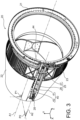
- the invention relates more specifically to a thrust reverser 20 as illustrated in Figures 3 to 9 , this inverter 20 having the function of reversing part of the thrust generated by such a propulsion unit 2 in order to brake the aircraft 1 during its landing.
- the inverter 20 can of course equip a propulsion unit different from that of the figure 2 without departing from the scope of the invention.
- the inverter 20 comprises a fixed structure comprising in particular a front frame 21.
- the front frame 21 is in this example intended to connect the inverter 20 to the nacelle 6 of the propulsion unit 2, by fixing this front frame 21 on a rear frame (not shown) of the nacelle 6.
- the inverter 20 further comprises a mobile external structure 22 forming a cover mobile in axial translation along the axis A1 relative to the fixed structure 21.
- the axis A1 here corresponds both to a longitudinal central axis of the inverter 20, to the longitudinal central axis of the turbojet 5 as well as to a longitudinal central axis of the propulsion assembly 2.
- the mobile external structure 22 is in this example an annular structure of axis A1 made from a single piece.
- the inverter 20 further comprises grids 23 configured to direct the diverted fluid flow towards the front of the propulsion assembly 2 to generate the counter-thrust (see further below).
- the grids 23 are integral with the mobile external structure 22. In an embodiment not shown, the grids 23 are integral with the fixed structure of the inverter 20.
- the thrust reverser 20 is intended to be mounted at the rear of the propulsion unit 2 so as to generate counter-thrust from a mixed flow comprising a mixture of the primary 14A and secondary 14B flows exiting respectively from the primary vein 15A and the secondary vein 15B of the propulsion unit 2.
- THE figures 3 , 5 , 8 And 9 show the inverter 20 in a direct thrust configuration, in which the movable external structure 22 is in a closed position, that is to say in an advanced position relative to the front frame 21 of the fixed structure.
- the mobile external structure 22 contributes to guiding the primary 14A and secondary 14B flows towards an ejection outlet downstream of the propulsion assembly 2 so as to generate thrust.
- the grids 23 are covered, in this case radially on the inside by an internal structure 30A (visible on the figures 5 And 9 ) and radially to the outside by an external fairing 30B (visible on the Figures 8 And 9 ).
- the internal structure 30A and the fairing 30B are integral with the front frame 21.
- the internal structure 30A is notably configured to prevent the fluid circulating in the propulsion assembly 2 from accessing the grids 23 and therefore from exiting the propulsion assembly 2 via the grids 23.
- THE figures 4 , 6 And 7 show the reverser 20 in a thrust reversal configuration, in which the movable external structure 22 is in an open position, that is to say in a position moved back relative to the front frame 21 of the fixed structure.
- the movable external structure 22 releases a radial opening allowing the mixed flow to be evacuated in order to generate counter-thrust.
- the radial opening is constituted by openings of the grilles 23, it being understood that the space situated axially between the grilles 23 and the front frame 21 remains closed by the internal structure 30A and the fairing 30B, since these are integral with the front frame 21.
- the inverter 20 does not include grids 23, the radial opening being constituted by an empty space corresponding substantially to the space occupied by the grids 23 in the embodiment of the Figures 3 to 9 .
- grids 23 are generally preferable because they make it possible to maximize the axial component of the flow at the outlet of the radial opening and consequently to increase the counter-thrust force, typically taking into account the curved shape of the blades (not shown) delimiting the openings of the grids 23.
- the reorientation of the primary 14A and secondary 14B flows towards the grids 23 is carried out by any conventional means, for example using pivoting flaps (not shown) connected on the one hand to the mobile external structure 22 and on the other hand to the fixed structure of the reverser 20 so as to deploy radially in the propulsion assembly 2 when the mobile external structure 22 is open and to retract when the latter is closed.
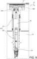
- the movement of the movable external structure 22 between the closed and open positions is carried out by a single actuator 25.
- the actuator 25 is a cylinder extending along an actuation axis A2 substantially parallel to the longitudinal central axis A1.
- the cylinder 25 conventionally comprises a body 26 forming a fixed part of this cylinder 25 and a rod 27 forming a movable part of this cylinder 25.
- the rod 27 is secured to a piston (not shown) housed in a cylindrical interior volume (not shown) of the body 26, the piston separating this cylindrical volume into two hermetic chambers isolated from each other.
- the volume of these two chambers is not identical since one of them is crossed by the rod 27 connected to the piston.
- the introduction of a pressurized fluid into the larger chamber, or large chamber, allows the piston and the rod 27 to be moved in a first direction of movement along the axis A2, causing the cylinder 25 to deploy.
- the introduction of a pressurized fluid into the smaller chamber, or small chamber allows the piston and the rod 27 to be moved in a second direction of movement along the axis A2, causing the cylinder 25 to retract.
- the body 26 comprises two axial ends, in this case a front end located on the side of the rod 27 and a rear end opposite the front end.
- the cylinder 25 is configured to place the movable external structure 22 in the open position when the cylinder 25 is retracted and to place the movable external structure 22 in the closed position when the cylinder 25 is deployed.
- the body 26 of the cylinder 25 is in this example connected to the fixed structure of the inverter 20 by its rear end 28 and the cylinder 25 is oriented towards the front of the inverter 20, that is to say towards the front frame 21.
- the free end of the rod 27, that is to say the end opposite that which is connected to the piston, is connected to a part 45 secured to the mobile external structure 22 (see further below).
- Such a configuration of the cylinder 25 makes it possible to reduce its dimensions since the force provided by this cylinder during the pressurization of the large chamber is used to close, over-retract and slow down the opening of the mobile external structure 22, while the force provided during the pressurization of the small chamber is used to open the mobile external structure 22.
- the force required to close the mobile external structure 22 is in fact greater than the force required to open this structure 22, the latter being in particular subjected to aerodynamic forces having an axial component oriented from upstream to downstream.
- the guidance of the movable external structure 22 during its movement between the closed and open positions is ensured simultaneously by a main guide device described below and by an auxiliary guide device 50 visible in the Figures 5 and 6 .
- the main guide device comprises in this example a slide 40 formed by two rails 41 and 42 secured to the fixed structure of the inverter 20.
- the rails 41 and 42 are visible on the figures 3 , 4 And 7 .
- the rails 41 and 42 extend parallel to the actuation axis A2, on either side of the jack 25, so that the latter is housed between the rails 41 and 42.
- the jack 25 is housed in the slide 40 over its entire length.
- the rear end 28 of the body 26 of the jack 25 is connected to a rear end 43 of the slide 40 (see figure 4 ).
- the rails 41 and 42 are sized so as to extend on either side of the rod 27, including when the jack 25 is deployed.
- said free end of the rod 27 is axially located at a front end 44 of the slide 40 (see figure 3 ).
- the main guide device also comprises a sliding part 45 secured to the movable external structure 22.
- the sliding part 45 is connected to the movable external structure 22 so as to extend radially towards the outside of this structure 22.
- the sliding part 45 has a shape complementary to that of the rails 41 and 42 (see figure 7 ) allowing it to slide along the slide 40 when the movable external structure 22 is moved between the closed and open positions, and thus ensuring the guidance of the movable external structure 22 during such a movement.
- the sliding part 45 is in this example connected to the rod 27 of the jack 25 by means of a drive shaft 46 extending perpendicularly to the actuation axis A2.
- the drive shaft 46 passes through both an orifice (not shown) made in said free end of the rod 27 and orifices (not shown) made in a connecting member 47 of the sliding part 45.
- the member connecting rod 47 here comprises two legs extending on either side of the free end of the rod 27.
- the auxiliary guide device 50 is not shown in the figures 3 And 4 but is visible on the figure 6 .
- This device 50 conventionally comprises rails secured to the fixed structure of the inverter 20 and a sliding part secured to the mobile external structure 22.
- He is represented at the figure 3 two median longitudinal planes P1 and P2 allowing the different elements of the inverter 20 to be located in relation to each other.
- Each of these fictitious planes P1 and P2 is a median plane in the sense that it passes through the axis A1 which is a central axis of the inverter 20, and a longitudinal plane since the axis A1 is also a longitudinal axis parallel to the longitudinal direction Z.
- the plane P2 also passes through the actuation axis A2 of the cylinder 25, and the plane P1 is perpendicular to the plane P2.
- the cylinder 25 and the main guide device are both located on the same side of the plane P1 and the auxiliary guide device 50 is located on the other side of the plane P1.
- the cylinder 25 and the main and auxiliary guide devices are each crossed by the plane P2.
- the rails 41 and 42 are located on either side of the jack 25 and consequently of the plane P2. Although neither of these rails 41 and 42 is as such crossed by the plane P2, the main guide device, which comprises the two rails 41 and 42 and the sliding part 45, is as a whole crossed by the plane P2.
- the actuator 25 and the guidance device are in this example sheltered by a fairing 60 of a mast (not shown in this figure) for attaching the propulsion unit 2 to the fuselage 3 of the aircraft 1, or more generally to a mast for attaching the propulsion unit 2 to an aircraft.
- the movable external structure 22 is configured to direct the flow of fluid generating the thrust in a direction oblique to the axis central longitudinal A1, more precisely so that the flow leaving the propulsion unit 2 tends to move away from the mast.
- the mobile external structure 22 comprises for this purpose an outlet end 221 defining a transverse plane forming an angle B1 relative to the lateral direction X, this transverse plane consequently being oblique relative to the first median longitudinal plane P1 and forming with this plane P1 an angle B2 complementary to B1.
- Such a geometry of the output end 221 of the mobile external structure 22 makes it possible to direct the thrust away from the mast, that is to say towards the side of the plane P1 opposite the side where the actuator 25 and the main guide device are located.
- the thrust thus oriented generates on the mobile external structure 22 a force tending to tilt this structure around the vertical direction Y.
- this tilting moment is compensated by the action of two primary locks 70 which are offset relative to the axis A1 and relative to the plane P1, in the lateral direction X outwards relative to the mast.
- the primary locks 70 make it possible to lock the movable external structure 22 in the closed position. Only one of these locks 70 is shown in the figure 5 .
- the primary lock 70 visible on the figure 5 mainly comprises a first hooking element 71 secured to the movable external structure 22 and a second hooking element 72 secured to the fixed structure 21 of the inverter 20.
- the first and second hooking elements 71 and 72 extend along a locking axis A3 substantially parallel to the longitudinal central axis A1 and can be moved between a locking state and an unlocking state using any conventional control means.
- the first and second hooking elements 71 and 72 cooperate with each other so as to lock the movable external structure 22 in the closed position (see figure 5 ).
- the first and second hooking elements 71 and 72 are separated from each other. to allow the movable external structure 22 to be moved between the closed and open positions under the action of the cylinder 25.
- the other primary lock is similar to the one just described.
- the two primary locks 70 are located in a locking plane parallel to the median longitudinal plane P1. This locking plane passes through the respective locking axis A3 of each of these locks.
- each of the two primary locks 70 is in this example positioned at an angular distance from the actuator 25 of approximately 110°. This angular distance depends in particular on the angle B1 of the output end 221 of the mobile external structure 22 since this angle has a direct impact on the amplitude of the tilting moment.
- the primary locks 70 are on the one hand both located on the side of the median longitudinal plane P1 opposite the side where the actuator 25 is located.
- the thrust flow moving away from the actuator 25, this configuration makes it possible to compensate for the tilting moment and thus to limit the deformations of the mobile external structure 22.
- the primary lock 70 visible on the figure 5 is located on one side of the median longitudinal plane P2 while the other primary lock, not visible, is located on the other side of this plane P2.
- the inverter 20 may comprise end-of-travel stops (not shown) configured to axially retain the movable external structure 22 in the open position.
- one of these stops is located on the same side of the plane P1 as the actuator 25 and is centered relative to the plane P2.
- the other stops may be positioned equidistant from each other so that each of them is crossed either by the plane P1 or by the plane P2.
- the movable external structure 22 is a structure known as an “O-Duct”, i.e. a quasi-annular monobloc structure comprising a mast passage opening.
Landscapes
- Engineering & Computer Science (AREA)
- Chemical & Material Sciences (AREA)
- Combustion & Propulsion (AREA)
- Mechanical Engineering (AREA)
- General Engineering & Computer Science (AREA)
- Transmission Devices (AREA)
- Sliding-Contact Bearings (AREA)
Claims (9)
- Schubumkehrvorrichtung (20) für eine Antriebsanordnung (2) eines Flugzeugs (1), wobei die Umkehrvorrichtung (20) umfasst:- eine bewegliche äußere Struktur (22), die eine längs gerichtete Mittelachse (A1) aufweist, wobei die äußere Struktur (22) beweglich ist, zwischen einer geschlossenen Position, in der sie in der Lage ist, einen Fluidstrom durch die Antriebsanordnung (2) zu leiten, um einen Schub zu erzeugen, und einer geöffneten Position, in der die bewegliche äußere Struktur (22) eine radiale Öffnung freigibt, die in der Lage ist, einen Teil des Fluidstroms aus der Antriebsanordnung (2) abzuleiten, um einen Gegenschub zu erzeugen,- einen Aktuator (25), wie z. B. einen Zylinder, der konfiguriert ist, um die bewegliche äußere Struktur (22) zwischen der geschlossenen und der geöffneten Position zu verschieben,- zwei primäre Verriegelungen (70), die konfiguriert sind, um die bewegliche äußere Struktur (22) in der geschlossenen Position zu verriegeln,wobei die Umkehrvorrichtung (20) konfiguriert ist, um den Fluidstrom, der den Schub erzeugt, entlang einer in Bezug auf die längs gerichtete Mittelachse (A1) schrägen Richtung zu einer ersten Seite einer ersten Längsmittelebene (P1), die durch die längs gerichtete Mittelachse (A1) verläuft, zu lenken, wobei die Umkehrvorrichtung (20) dadurch gekennzeichnet ist, dass die bewegliche äußere Struktur (22) ringförmig ist, dass die primären Verriegelungen (70) beide auf der ersten Seite der ersten Längsmittelebene (P1) angeordnet sind, und dass der Aktuator (25) auf der anderen Seite der ersten Längsmittelebene (P1) angeordnet ist, wobei eine der primären Verriegelungen (70) auf einer Seite einer zweiten Längsmittelebene (P2) angeordnet ist, die senkrecht zur ersten Längsmittelebene (P1) ist, und die andere primäre Verriegelung auf der anderen Seite der zweiten Längsmittelebene (P2) angeordnet ist.
- Schubumkehrvorrichtung (20) nach Anspruch 1, wobei die bewegliche äußere Struktur (22) ein Auslassende (221) umfasst, das eine Querebene definiert, die in Bezug zur ersten Längsmittelebene (P1) schräg verläuft, so dass der Fluidstrom, der den Schub erzeugt, entlang der schrägen Richtung gelenkt wird.
- Schubumkehrvorrichtung (20) nach Anspruch 1 oder 2, wobei die zwei primären Verriegelungen (70) in einer Verriegelungsebene angeordnet sind, die parallel zur ersten Längsmittelebene (P1) ist.
- Schubumkehrvorrichtung (20) nach einem der Ansprüche 1 bis 3, wobei jede der zwei primären Verriegelungen (70) in einem Winkelabstand vom Aktuator (25) positioniert ist, der zwischen 100° und 120° liegt, vorzugsweise etwa 110°.
- Schubumkehrvorrichtung (20) nach einem der Ansprüche 1 bis 4, wobei der Aktuator (25) einmalig ist.
- Schubumkehrvorrichtung (20) nach einem der Ansprüche 1 bis 5, wobei der Aktuator (25) von der zweiten Längsmittelebene (P2) durchquert wird.
- Antriebsanordnung (2) eines Flugzeugs (1), wobei die Antriebsanordnung (2) eine Schubumkehrvorrichtung (20) nach einem der Ansprüche 1 bis 6 umfasst.
- Antriebsanordnung (2) nach Anspruch 7, wobei die Antriebsanordnung (2) einen Mast (60A, 60B) zum Einhängen der Antriebsanordnung (2) an einem Rumpf (3) des Flugzeugs (1) umfasst, wobei der Mast (60A, 60B) eine Verkleidung (60) umfasst, die den Aktuator (25) unterbringt.
- Flugzeug (1), mindestens eine Antriebsanordnung (2) nach Anspruch 7 oder 8 umfassend.
Applications Claiming Priority (2)
| Application Number | Priority Date | Filing Date | Title |
|---|---|---|---|
| FR1909759A FR3100576B1 (fr) | 2019-09-05 | 2019-09-05 | Inverseur de poussée comprenant des verrous primaires décalés par rapport à un plan de symétrie du capot mobile |
| PCT/FR2020/051520 WO2021044097A1 (fr) | 2019-09-05 | 2020-09-02 | Inverseur de poussée comprenant des verrous primaires décalés par rapport à un plan de symétrie du capot mobile |
Publications (2)
| Publication Number | Publication Date |
|---|---|
| EP4025779A1 EP4025779A1 (de) | 2022-07-13 |
| EP4025779B1 true EP4025779B1 (de) | 2024-10-30 |
Family
ID=68211102
Family Applications (1)
| Application Number | Title | Priority Date | Filing Date |
|---|---|---|---|
| EP20775915.0A Active EP4025779B1 (de) | 2019-09-05 | 2020-09-02 | Schubumkehrvorrichtung mit gegenüber einer symmetrieebene der beweglichen haube versetzten primärriegeln |
Country Status (5)
| Country | Link |
|---|---|
| US (1) | US12372047B2 (de) |
| EP (1) | EP4025779B1 (de) |
| CA (1) | CA3152380A1 (de) |
| FR (1) | FR3100576B1 (de) |
| WO (1) | WO2021044097A1 (de) |
Families Citing this family (1)
| Publication number | Priority date | Publication date | Assignee | Title |
|---|---|---|---|---|
| FR3123388B1 (fr) * | 2021-05-31 | 2024-01-19 | Safran Nacelles | Ensemble inverseur de poussée pour turboréacteur |
Family Cites Families (15)
| Publication number | Priority date | Publication date | Assignee | Title |
|---|---|---|---|---|
| US3419218A (en) * | 1967-02-23 | 1968-12-31 | Mc Donnell Douglas Corp | Thrust reverser |
| GB1583952A (en) * | 1976-07-13 | 1981-02-04 | Short Brothers & Harland Ltd | Gas turbine engines |
| US5230213A (en) * | 1991-06-12 | 1993-07-27 | Rohr, Inc. | Aircraft turbine engine thrust reverser |
| US7093424B2 (en) * | 2004-08-24 | 2006-08-22 | Honeywell International, Inc. | Thrust reverser system electro-mechanical brake manual release mechanism |
| FR2896772B1 (fr) * | 2006-01-27 | 2008-04-25 | Snecma Sa | Systeme d' ejection d'un turboreacteur a double flux |
| US8959889B2 (en) * | 2008-11-26 | 2015-02-24 | The Boeing Company | Method of varying a fan duct nozzle throat area of a gas turbine engine |
| US8127532B2 (en) * | 2008-11-26 | 2012-03-06 | The Boeing Company | Pivoting fan nozzle nacelle |
| FR2958910B1 (fr) * | 2010-04-20 | 2012-04-27 | Aircelle Sa | Nacelle pour moteur d'aeronef a tuyere de section variable |
| FR2974150B1 (fr) * | 2011-04-14 | 2013-04-12 | Aircelle Sa | Inverseur de poussee pour turboreacteur d'aeronef |
| FR2980173B1 (fr) * | 2011-09-16 | 2013-10-25 | Aircelle Sa | Ensemble arriere de nacelle pour turboreacteur |
| FR2983173B1 (fr) * | 2011-11-24 | 2014-02-28 | Aircelle Sa | Actionneur pour nacelle de turboreacteur d'aeronef a partie arriere notamment annulaire monobloc |
| FR2998619B1 (fr) * | 2012-11-28 | 2021-05-07 | Aircelle Sa | Verrou actif avec assistance de mobilisation et inverseur de poussee incorporant un tel verrou |
| GB201314527D0 (en) * | 2013-08-14 | 2013-09-25 | Rolls Royce Deutschland | Thrust reverser unit |
| US20170283081A1 (en) * | 2016-04-05 | 2017-10-05 | Rohr, Inc. | Securing a translating fanlet for an aircraft propulsion system nacelle |
| DE102017115644A1 (de) * | 2017-07-12 | 2019-01-17 | Rolls-Royce Deutschland Ltd & Co Kg | Turbofantriebwerk |
-
2019
- 2019-09-05 FR FR1909759A patent/FR3100576B1/fr active Active
-
2020
- 2020-09-02 CA CA3152380A patent/CA3152380A1/en active Pending
- 2020-09-02 US US17/640,112 patent/US12372047B2/en active Active
- 2020-09-02 WO PCT/FR2020/051520 patent/WO2021044097A1/fr not_active Ceased
- 2020-09-02 EP EP20775915.0A patent/EP4025779B1/de active Active
Also Published As
| Publication number | Publication date |
|---|---|
| EP4025779A1 (de) | 2022-07-13 |
| FR3100576A1 (fr) | 2021-03-12 |
| US12372047B2 (en) | 2025-07-29 |
| WO2021044097A1 (fr) | 2021-03-11 |
| US20220307446A1 (en) | 2022-09-29 |
| FR3100576B1 (fr) | 2021-09-17 |
| CA3152380A1 (en) | 2021-03-11 |
Similar Documents
| Publication | Publication Date | Title |
|---|---|---|
| EP2773861B1 (de) | Schubumkehrvorrichtung mit einteiliger mobiler haube | |
| EP3415749B1 (de) | Gondel mit schubumkehrsystem, das begrenzte aerodynamische störungen aufweist | |
| EP2737231B1 (de) | Doppeltwirkender linearantrieb | |
| EP2859213A1 (de) | Schubumkehrvorrichtung mit einziehbaren kaskadenschaufeln | |
| EP2625388A1 (de) | Schubumkehrer | |
| EP3191368B1 (de) | Antriebseinheit für ein flugzeug und verfahren zur öffnung einer beweglichen haube der besagten antriebseinheit | |
| FR3031727A1 (fr) | Dispositif d’inversion de poussee a grilles mobiles et berceau pour nacelle pour mat du type corps | |
| EP4288652B1 (de) | Schubumkehrvorrichtung mit beweglichen gittern und durch aussparung montierten hauben | |
| EP3947950B1 (de) | Tür für schubumkehrvorrichtung einer flugzeugantriebsanordnung mit einer flexiblen ablenkplatte | |
| EP4025781B1 (de) | Schubumkehrvorrichtung, die ein einziges stellglied zur steuerung einer beweglichen verkleidung umfasst | |
| EP4025779B1 (de) | Schubumkehrvorrichtung mit gegenüber einer symmetrieebene der beweglichen haube versetzten primärriegeln | |
| EP4085189B1 (de) | Schubumkehrvorrichtung mit türen und mindestens einem zurückziehbaren deflektor zum verschliessen einer seitlichen öffnung | |
| EP3856639B1 (de) | Flugzeuggondel und zugehöriger lufteinlass | |
| EP4172481B1 (de) | Schubumkehrvorrichtung mit drei toren | |
| EP3963201B1 (de) | Schubumkehrer mit beweglicher haube mit schubreduzierungsmechanismus, der unabhängig von der beweglichen haube ist | |
| EP4594610A1 (de) | Schubumkehrvorrichtung mit einem verbesserten system zum bewegen der beweglichen struktur in die eingezogene schubumkehrposition davon | |
| WO2017220898A1 (fr) | Réglage axial du translating cowl par excentrique | |
| FR3140403A1 (fr) | Inverseur de poussee comprenant un systeme ameliore de deplacement de la structure mobile vers sa position reculee d’inversion de poussee | |
| EP4323631A1 (de) | Schubumkehrvorrichtung mit beweglicher kaszade mit einer multifunktionalen festen struktur |
Legal Events
| Date | Code | Title | Description |
|---|---|---|---|
| STAA | Information on the status of an ep patent application or granted ep patent |
Free format text: STATUS: UNKNOWN |
|
| STAA | Information on the status of an ep patent application or granted ep patent |
Free format text: STATUS: THE INTERNATIONAL PUBLICATION HAS BEEN MADE |
|
| PUAI | Public reference made under article 153(3) epc to a published international application that has entered the european phase |
Free format text: ORIGINAL CODE: 0009012 |
|
| STAA | Information on the status of an ep patent application or granted ep patent |
Free format text: STATUS: REQUEST FOR EXAMINATION WAS MADE |
|
| 17P | Request for examination filed |
Effective date: 20220308 |
|
| AK | Designated contracting states |
Kind code of ref document: A1 Designated state(s): AL AT BE BG CH CY CZ DE DK EE ES FI FR GB GR HR HU IE IS IT LI LT LU LV MC MK MT NL NO PL PT RO RS SE SI SK SM TR |
|
| RIN1 | Information on inventor provided before grant (corrected) |
Inventor name: CHAPELAIN, LOIC Inventor name: BRAVIN, FABIEN Inventor name: CHARLIAC, FABIEN Inventor name: CARUEL, PIERRE, CHARLES |
|
| DAV | Request for validation of the european patent (deleted) | ||
| DAX | Request for extension of the european patent (deleted) | ||
| GRAP | Despatch of communication of intention to grant a patent |
Free format text: ORIGINAL CODE: EPIDOSNIGR1 |
|
| STAA | Information on the status of an ep patent application or granted ep patent |
Free format text: STATUS: GRANT OF PATENT IS INTENDED |
|
| INTG | Intention to grant announced |
Effective date: 20240723 |
|
| GRAS | Grant fee paid |
Free format text: ORIGINAL CODE: EPIDOSNIGR3 |
|
| GRAA | (expected) grant |
Free format text: ORIGINAL CODE: 0009210 |
|
| STAA | Information on the status of an ep patent application or granted ep patent |
Free format text: STATUS: THE PATENT HAS BEEN GRANTED |
|
| AK | Designated contracting states |
Kind code of ref document: B1 Designated state(s): AL AT BE BG CH CY CZ DE DK EE ES FI FR GB GR HR HU IE IS IT LI LT LU LV MC MK MT NL NO PL PT RO RS SE SI SK SM TR |
|
| REG | Reference to a national code |
Ref country code: GB Ref legal event code: FG4D Free format text: NOT ENGLISH |
|
| REG | Reference to a national code |
Ref country code: CH Ref legal event code: EP |
|
| REG | Reference to a national code |
Ref country code: DE Ref legal event code: R096 Ref document number: 602020040367 Country of ref document: DE |
|
| REG | Reference to a national code |
Ref country code: IE Ref legal event code: FG4D Free format text: LANGUAGE OF EP DOCUMENT: FRENCH |
|
| REG | Reference to a national code |
Ref country code: LT Ref legal event code: MG9D |
|
| REG | Reference to a national code |
Ref country code: NL Ref legal event code: MP Effective date: 20241030 |
|
| PG25 | Lapsed in a contracting state [announced via postgrant information from national office to epo] |
Ref country code: PT Free format text: LAPSE BECAUSE OF FAILURE TO SUBMIT A TRANSLATION OF THE DESCRIPTION OR TO PAY THE FEE WITHIN THE PRESCRIBED TIME-LIMIT Effective date: 20250228 Ref country code: IS Free format text: LAPSE BECAUSE OF FAILURE TO SUBMIT A TRANSLATION OF THE DESCRIPTION OR TO PAY THE FEE WITHIN THE PRESCRIBED TIME-LIMIT Effective date: 20250228 Ref country code: HR Free format text: LAPSE BECAUSE OF FAILURE TO SUBMIT A TRANSLATION OF THE DESCRIPTION OR TO PAY THE FEE WITHIN THE PRESCRIBED TIME-LIMIT Effective date: 20241030 |
|
| PG25 | Lapsed in a contracting state [announced via postgrant information from national office to epo] |
Ref country code: FI Free format text: LAPSE BECAUSE OF FAILURE TO SUBMIT A TRANSLATION OF THE DESCRIPTION OR TO PAY THE FEE WITHIN THE PRESCRIBED TIME-LIMIT Effective date: 20241030 Ref country code: NL Free format text: LAPSE BECAUSE OF FAILURE TO SUBMIT A TRANSLATION OF THE DESCRIPTION OR TO PAY THE FEE WITHIN THE PRESCRIBED TIME-LIMIT Effective date: 20241030 |
|
| REG | Reference to a national code |
Ref country code: AT Ref legal event code: MK05 Ref document number: 1737077 Country of ref document: AT Kind code of ref document: T Effective date: 20241030 |
|
| PG25 | Lapsed in a contracting state [announced via postgrant information from national office to epo] |
Ref country code: BG Free format text: LAPSE BECAUSE OF FAILURE TO SUBMIT A TRANSLATION OF THE DESCRIPTION OR TO PAY THE FEE WITHIN THE PRESCRIBED TIME-LIMIT Effective date: 20241030 |
|
| PG25 | Lapsed in a contracting state [announced via postgrant information from national office to epo] |
Ref country code: ES Free format text: LAPSE BECAUSE OF FAILURE TO SUBMIT A TRANSLATION OF THE DESCRIPTION OR TO PAY THE FEE WITHIN THE PRESCRIBED TIME-LIMIT Effective date: 20241030 |
|
| PG25 | Lapsed in a contracting state [announced via postgrant information from national office to epo] |
Ref country code: NO Free format text: LAPSE BECAUSE OF FAILURE TO SUBMIT A TRANSLATION OF THE DESCRIPTION OR TO PAY THE FEE WITHIN THE PRESCRIBED TIME-LIMIT Effective date: 20250130 |
|
| PG25 | Lapsed in a contracting state [announced via postgrant information from national office to epo] |
Ref country code: LV Free format text: LAPSE BECAUSE OF FAILURE TO SUBMIT A TRANSLATION OF THE DESCRIPTION OR TO PAY THE FEE WITHIN THE PRESCRIBED TIME-LIMIT Effective date: 20241030 Ref country code: AT Free format text: LAPSE BECAUSE OF FAILURE TO SUBMIT A TRANSLATION OF THE DESCRIPTION OR TO PAY THE FEE WITHIN THE PRESCRIBED TIME-LIMIT Effective date: 20241030 Ref country code: GR Free format text: LAPSE BECAUSE OF FAILURE TO SUBMIT A TRANSLATION OF THE DESCRIPTION OR TO PAY THE FEE WITHIN THE PRESCRIBED TIME-LIMIT Effective date: 20250131 |
|
| PG25 | Lapsed in a contracting state [announced via postgrant information from national office to epo] |
Ref country code: PL Free format text: LAPSE BECAUSE OF FAILURE TO SUBMIT A TRANSLATION OF THE DESCRIPTION OR TO PAY THE FEE WITHIN THE PRESCRIBED TIME-LIMIT Effective date: 20241030 |
|
| PG25 | Lapsed in a contracting state [announced via postgrant information from national office to epo] |
Ref country code: RS Free format text: LAPSE BECAUSE OF FAILURE TO SUBMIT A TRANSLATION OF THE DESCRIPTION OR TO PAY THE FEE WITHIN THE PRESCRIBED TIME-LIMIT Effective date: 20250130 |
|
| PG25 | Lapsed in a contracting state [announced via postgrant information from national office to epo] |
Ref country code: SM Free format text: LAPSE BECAUSE OF FAILURE TO SUBMIT A TRANSLATION OF THE DESCRIPTION OR TO PAY THE FEE WITHIN THE PRESCRIBED TIME-LIMIT Effective date: 20241030 |
|
| PG25 | Lapsed in a contracting state [announced via postgrant information from national office to epo] |
Ref country code: DK Free format text: LAPSE BECAUSE OF FAILURE TO SUBMIT A TRANSLATION OF THE DESCRIPTION OR TO PAY THE FEE WITHIN THE PRESCRIBED TIME-LIMIT Effective date: 20241030 |
|
| PG25 | Lapsed in a contracting state [announced via postgrant information from national office to epo] |
Ref country code: EE Free format text: LAPSE BECAUSE OF FAILURE TO SUBMIT A TRANSLATION OF THE DESCRIPTION OR TO PAY THE FEE WITHIN THE PRESCRIBED TIME-LIMIT Effective date: 20241030 |
|
| PG25 | Lapsed in a contracting state [announced via postgrant information from national office to epo] |
Ref country code: RO Free format text: LAPSE BECAUSE OF FAILURE TO SUBMIT A TRANSLATION OF THE DESCRIPTION OR TO PAY THE FEE WITHIN THE PRESCRIBED TIME-LIMIT Effective date: 20241030 |
|
| PG25 | Lapsed in a contracting state [announced via postgrant information from national office to epo] |
Ref country code: SK Free format text: LAPSE BECAUSE OF FAILURE TO SUBMIT A TRANSLATION OF THE DESCRIPTION OR TO PAY THE FEE WITHIN THE PRESCRIBED TIME-LIMIT Effective date: 20241030 |
|
| PG25 | Lapsed in a contracting state [announced via postgrant information from national office to epo] |
Ref country code: CZ Free format text: LAPSE BECAUSE OF FAILURE TO SUBMIT A TRANSLATION OF THE DESCRIPTION OR TO PAY THE FEE WITHIN THE PRESCRIBED TIME-LIMIT Effective date: 20241030 |
|
| PG25 | Lapsed in a contracting state [announced via postgrant information from national office to epo] |
Ref country code: IT Free format text: LAPSE BECAUSE OF FAILURE TO SUBMIT A TRANSLATION OF THE DESCRIPTION OR TO PAY THE FEE WITHIN THE PRESCRIBED TIME-LIMIT Effective date: 20241030 |
|
| REG | Reference to a national code |
Ref country code: DE Ref legal event code: R097 Ref document number: 602020040367 Country of ref document: DE |
|
| PLBE | No opposition filed within time limit |
Free format text: ORIGINAL CODE: 0009261 |
|
| STAA | Information on the status of an ep patent application or granted ep patent |
Free format text: STATUS: NO OPPOSITION FILED WITHIN TIME LIMIT |
|
| PG25 | Lapsed in a contracting state [announced via postgrant information from national office to epo] |
Ref country code: SE Free format text: LAPSE BECAUSE OF FAILURE TO SUBMIT A TRANSLATION OF THE DESCRIPTION OR TO PAY THE FEE WITHIN THE PRESCRIBED TIME-LIMIT Effective date: 20241030 |
|
| 26N | No opposition filed |
Effective date: 20250731 |
|
| PGFP | Annual fee paid to national office [announced via postgrant information from national office to epo] |
Ref country code: DE Payment date: 20250919 Year of fee payment: 6 |
|
| PGFP | Annual fee paid to national office [announced via postgrant information from national office to epo] |
Ref country code: GB Payment date: 20250923 Year of fee payment: 6 |
|
| PGFP | Annual fee paid to national office [announced via postgrant information from national office to epo] |
Ref country code: FR Payment date: 20250917 Year of fee payment: 6 |