EP4025491B1 - Weak soil anchor device to anchor one or several structures and method to arrange an anchor in weak soil - Google Patents
Weak soil anchor device to anchor one or several structures and method to arrange an anchor in weak soil Download PDFInfo
- Publication number
- EP4025491B1 EP4025491B1 EP20860825.7A EP20860825A EP4025491B1 EP 4025491 B1 EP4025491 B1 EP 4025491B1 EP 20860825 A EP20860825 A EP 20860825A EP 4025491 B1 EP4025491 B1 EP 4025491B1
- Authority
- EP
- European Patent Office
- Prior art keywords
- anchor device
- weak soil
- wall surface
- box structure
- weak
- Prior art date
- Legal status (The legal status is an assumption and is not a legal conclusion. Google has not performed a legal analysis and makes no representation as to the accuracy of the status listed.)
- Active
Links
Images


Classifications
-
- B—PERFORMING OPERATIONS; TRANSPORTING
- B63—SHIPS OR OTHER WATERBORNE VESSELS; RELATED EQUIPMENT
- B63B—SHIPS OR OTHER WATERBORNE VESSELS; EQUIPMENT FOR SHIPPING
- B63B21/00—Tying-up; Shifting, towing, or pushing equipment; Anchoring
- B63B21/24—Anchors
- B63B21/26—Anchors securing to bed
-
- B—PERFORMING OPERATIONS; TRANSPORTING
- B63—SHIPS OR OTHER WATERBORNE VESSELS; RELATED EQUIPMENT
- B63B—SHIPS OR OTHER WATERBORNE VESSELS; EQUIPMENT FOR SHIPPING
- B63B21/00—Tying-up; Shifting, towing, or pushing equipment; Anchoring
- B63B21/24—Anchors
-
- E—FIXED CONSTRUCTIONS
- E02—HYDRAULIC ENGINEERING; FOUNDATIONS; SOIL SHIFTING
- E02D—FOUNDATIONS; EXCAVATIONS; EMBANKMENTS; UNDERGROUND OR UNDERWATER STRUCTURES
- E02D5/00—Bulkheads, piles, or other structural elements specially adapted to foundation engineering
- E02D5/74—Means for anchoring structural elements or bulkheads
- E02D5/80—Ground anchors
-
- B—PERFORMING OPERATIONS; TRANSPORTING
- B63—SHIPS OR OTHER WATERBORNE VESSELS; RELATED EQUIPMENT
- B63B—SHIPS OR OTHER WATERBORNE VESSELS; EQUIPMENT FOR SHIPPING
- B63B21/00—Tying-up; Shifting, towing, or pushing equipment; Anchoring
- B63B21/24—Anchors
- B63B21/30—Anchors rigid when in use
-
- E—FIXED CONSTRUCTIONS
- E02—HYDRAULIC ENGINEERING; FOUNDATIONS; SOIL SHIFTING
- E02D—FOUNDATIONS; EXCAVATIONS; EMBANKMENTS; UNDERGROUND OR UNDERWATER STRUCTURES
- E02D27/00—Foundations as substructures
- E02D27/32—Foundations for special purposes
- E02D27/50—Anchored foundations
-
- E—FIXED CONSTRUCTIONS
- E02—HYDRAULIC ENGINEERING; FOUNDATIONS; SOIL SHIFTING
- E02D—FOUNDATIONS; EXCAVATIONS; EMBANKMENTS; UNDERGROUND OR UNDERWATER STRUCTURES
- E02D27/00—Foundations as substructures
- E02D27/32—Foundations for special purposes
- E02D27/52—Submerged foundations, i.e. submerged in open water
- E02D27/525—Submerged foundations, i.e. submerged in open water using elements penetrating the underwater ground
-
- E—FIXED CONSTRUCTIONS
- E02—HYDRAULIC ENGINEERING; FOUNDATIONS; SOIL SHIFTING
- E02D—FOUNDATIONS; EXCAVATIONS; EMBANKMENTS; UNDERGROUND OR UNDERWATER STRUCTURES
- E02D2200/00—Geometrical or physical properties
- E02D2200/16—Shapes
- E02D2200/1678—Shapes triangular
-
- E—FIXED CONSTRUCTIONS
- E02—HYDRAULIC ENGINEERING; FOUNDATIONS; SOIL SHIFTING
- E02D—FOUNDATIONS; EXCAVATIONS; EMBANKMENTS; UNDERGROUND OR UNDERWATER STRUCTURES
- E02D9/00—Removing sheet piles bulkheads, piles, mould-pipes or other moulds or parts thereof
- E02D9/02—Removing sheet piles bulkheads, piles, mould-pipes or other moulds or parts thereof by withdrawing
Definitions
- the present invention relates to a weak soil anchor device for anchoring one or more structures.
- the invention further relates to a method for arranging an anchoring in weak soils for anchoring one or more structures using the weak soil anchor device.
- the anchor device is preferably formed to be pushed into the seabed with conventional piling frame equipment or possibly by means of a vibrohammer.
- Anchor piles normally designed as steel pipe piles. These are installed using pile hammers. These anchors normally have a small diameter and may give too low holding resistance. Furthermore, they have a constant cross-section which entails a relatively large material consumption in the upper soil layer with little holding resistance.
- Suction anker These are installed by mechanical pumps attached to the pile and sucked into the ground. These anchors have a constant cross-section which results in relatively large material consumption in the upper soil layer with little holding resistance. Furthermore, they require a lid on top to establish suction. They also require a special mechanical system to enable installation into the weak soils by means of suction.
- SEPLA anchors These are formed as a plate anchor and pressed into the uncompacted masses by means of a suction anchor. This normally results in a complicated operation.
- EP 0312198A1 discloses a pile which has high resistance to pulling when used as an anchor for horizontal or near-horizontal guidance.
- the pile has an elongated hollow body with a cross-sectional profile in the form of a closed figure which is asymmetrical about at least one axis, and is preferably triangular, especially an equilateral triangle whose equal angles are in the range 20-45 degrees.
- the pile body is preferably constructed of plate material, where at least the lower end is open, for easy driving into the carrier material (for example the seabed).
- a beam-like reinforcing member preferably extends over the interior of the pile body, for the full vertical length of the pile body, to strengthen the pile against bending when it its used for anchoring.
- a connecting element such as a hook, is located on the pile, preferably on an edge of the reinforcing beam.
- the vertical reinforcing beam forms the apex of an equilateral triangle between its equal side and at 35 degrees equal angles, and the connecting element is at the apex at about the middle length of the pile.
- Powerful marine anchoring systems are also disclosed which use the piles.
- US 3850128A discloses an anchor assembly for immersion in a formation below a body of water, comprising an anchor section with an elongate hollow shaft and radially extending tapered plates attached to the lower end thereof, a vibration drive unit and a releasable coupling for connecting said drive unit to said shaft .
- the vibrational forces fluidize the seabed whereby the anchor tends to sink by its own weight. After immersion, the coupling is deactivated to allow recovery of the drive.
- An object of the present invention is therefore to provide a weak soil anchor device which solves the disadvantages and problems of the known anchor types as discussed above.
- anchor device should be manufacturable and transportable in a cost-effective manner.
- a further object is that the anchor device should be installable in an exact, predetermined position by means of standard frame equipment for piles.
- a further object is that the weak soil anchor device should achieve high anchor capacity in deeper weak soils.
- a yet further object is that the anchor device should be adapted and dimensioned so that the anchor has a maximum holding capacity in at least three directions, whereby the anchor can be used as a common anchor for a number of constructions.
- a weak soil anchor device for anchoring one or more constructions characterized in that it, seen in a vertical operating position, comprises:
- the object of the present invention is further achieved by a method for arranging an anchoring in weak soils for anchoring one or more structures, where a weak soil anchor device according to any one of the preceding claims 1 to 12 is used, characterized in that it comprises:
- a preferred embodiment of the method is further elaborated in claim 14.
- the weak soil anchor device 1 for anchoring a number of structures.
- the weak soil anchor device 1 is shown in a vertical operating position.
- the weak soil anchor device 1 consists of an elongate continuous open box construction 2 with a triangular cross-section comprising a first wall plate 3, second wall plate 4 and a third wall plate 5.
- An outer continuous open box structure 10 with a smaller vertical extent than the inner box structure 2 and with a triangular cross-section consisting of a first outer wall plate 11, second outer wall plate 12 and third outer wall plate 13 is connected to the inner elongate continuous open box structure 2 in a lower area of this.
- the vertical center area 14 of the first, second and third outer wall surfaces is connected to, respectively, an outer edge area between the first and second wall surfaces 3, 4, second and third wall surfaces 4, 5 and the third and first wall surfaces 5, 3.
- an anchor bracket 20 is arranged respectively in each connecting area between the first and second outer wall surfaces 11, 12, second and third outer wall surfaces 12, 13 and third and first outer wall surfaces 13, 11. Further with reference to figure 2 the anchor bracket 20 is arranged respectively in each connecting area between the inner box structure 2 and the outer box structure 10.
- Anchor brackets 20 can also be arranged both in the corners of the outer box structure 10 and in the vertical center areas of the outer wall surfaces 11, 12, 13.
- the weak soil anchor device 1 here comprises a further outer continuous open box structure 25 with a triangular cross-section arranged externally of the outer continuous open box structure 10.
- the further outer open box structure 25 comprises a first further wall surface 26, a second further outer wall surface 27 and a third further outer wall surface 28.
- a vertical center area 29 of respectively the first, second and third further outer wall surfaces 26, 27, 28 is connected to respectively a lower connecting area between the first and second outer wall surfaces 11, 12, second and third outer wall surface 12, 13, third and first outer wall surface 13, 11.
- An anchor bracket 20 is shown here arranged in respectively each of the vertical center areas 29 of respectively the first, second and third further outer wall surface 26, 27, 28.
- the weak soil anchor device 1 is further provided with bracing wall surfaces 30 extending from the vertical center area 14 of the first, second and third outer wall surfaces 11, 12, 13 to respectively the first, second and third further outer wall surfaces 26, 27, 28.
- the bracing wall surface 30 in this embodiment forms an angle within the range of respectively 60° and 120° with the first, second and third further outer wall surfaces 26, 27, 28.
- the further outer box construction 25 in this embodiment has a smaller vertical extent than the outer box construction 10. It should be mentioned in this connection that the further outer box construction 25 does not necessarily needs to extend as deep as the outer box construction 10.
- the elongate inner continuous open box structure 2, the outer continuous open box structure 10 and the further outer continuous open box structure 25 each have a cross section in the form of an equilateral triangle.
- the box constructions 2, 10, 25 can also have a triangular-shaped cross-section which is not an equilateral triangle.
- the anchor brackets 20 for anchor lines are fastened in the lower part of the weak soil anchor device 1, where the total, resulting holding resistance from the adjacent ground masses acts based on the distribution of the ground resistance over the height of the anchor device. In this way, the weak soil anchor device 1 will be able to utilize the horizontal ground resistance.
- the anchor device 1 can be formed by varying its geometry such as for example:
- the weak soil anchor device 1 is as shown in figure 1 formed from straight plates which offer a simple and cost-effective manufacturing method.
- the anchor device can be manufactured and transported in a lying position.
- the weak soil anchor device 1 with the triangular box structure cross-section mean that the forces from the anchor line are distributed over the total height of the anchor device 1 to the surrounding weak soils by the inherent properties of the open box structure as a continuous beam.
- the anchor construction 1 is suitable for sharing of anchors, for example that a number of floats connect to the same anchor in a wind farm. In such a case the anchor device 1 must take loads from different directions.
- the anchor device 1 is formed to take loads in three directions and further regarding the best holding capacity being achieved deeper in the ground, whereby the majority of the structure's material (steel, concrete) is placed in this area.
- the principles are that there is greater holding capacity deeper in the ground and that it is therefore effective to use more material deep down, while the upper part of the anchor device 1 is more to get the anchor device 1 pressed into the ground.
- the triangular-shaped box constructions 2, 10, 25 facilitate large dimensions at the bottom and at the same time minimal dimensions in the upper part that contribute little to the holding force.
- the weak soil anchor device 1 is formed with a view to being pressed down into the seabed by means of conventional frame equipment for piling.
- the frame equipment can, for example, be conventional pile hammers (drop weights or hydraulic hammers) or vibrohammers.
- Reinforcement plates 7 are arranged inside in an upper area of the corners of the inner continuous box construction 2 to facilitate the use of piling equipment.
- the piling equipment can advantageously be mounted on the anchor device 1 on board a suitable installation vessel and lowered as a unit down to the seabed. Further driving of the anchor device 1 down into the weak soils takes place as for framing of free-standing piles.
- the weak soil anchor device 1 is formed so that installation thereof does not have any limitations regarding soil profile. Different soil profiles will therefore not limit the use of the weak soil anchor device 1. The soil profiles often show an increasing firmness with depth.
- the present weak soil anchor device 1 is, as previously described, formed so that it uses as little construction material as possible in the upper soil layer, but uses more construction material in deeper and firmer soil layers. There is no need to use specially made auxiliary equipment beyond standard pile hammers for installation.
- the anchor device 1 can be installed in an exact, predetermined position.
Landscapes
- Engineering & Computer Science (AREA)
- Structural Engineering (AREA)
- Civil Engineering (AREA)
- Life Sciences & Earth Sciences (AREA)
- General Life Sciences & Earth Sciences (AREA)
- Mining & Mineral Resources (AREA)
- Paleontology (AREA)
- General Engineering & Computer Science (AREA)
- Mechanical Engineering (AREA)
- Ocean & Marine Engineering (AREA)
- Chemical & Material Sciences (AREA)
- Combustion & Propulsion (AREA)
- Piles And Underground Anchors (AREA)
- Foundations (AREA)
Description
- The present invention relates to a weak soil anchor device for anchoring one or more structures. The invention further relates to a method for arranging an anchoring in weak soils for anchoring one or more structures using the weak soil anchor device. The anchor device is preferably formed to be pushed into the seabed with conventional piling frame equipment or possibly by means of a vibrohammer.
- Various anchor types are known today within the scope of the present invention as defined by the appended claims, and examples of some of these are discussed below.
- Conventional plate anchors or ship anchors, for example of "Vryhof" type. These are formed so that vessels with high towing power pull the anchors so that they dig down into the seabed. These anchor types are widely used, but also have some disadvantages. In some cases, the weak soils are of such a nature that the anchors cannot be pulled down to a sufficiently large depth to achieve the necessary holding force.
- Anchor piles normally designed as steel pipe piles. These are installed using pile hammers. These anchors normally have a small diameter and may give too low holding resistance. Furthermore, they have a constant cross-section which entails a relatively large material consumption in the upper soil layer with little holding resistance.
- Suction anker. These are installed by mechanical pumps attached to the pile and sucked into the ground. These anchors have a constant cross-section which results in relatively large material consumption in the upper soil layer with little holding resistance. Furthermore, they require a lid on top to establish suction. They also require a special mechanical system to enable installation into the weak soils by means of suction.
- SEPLA anchors. These are formed as a plate anchor and pressed into the uncompacted masses by means of a suction anchor. This normally results in a complicated operation.
-
EP 0312198A1 discloses a pile which has high resistance to pulling when used as an anchor for horizontal or near-horizontal guidance. The pile has an elongated hollow body with a cross-sectional profile in the form of a closed figure which is asymmetrical about at least one axis, and is preferably triangular, especially an equilateral triangle whose equal angles are in the range 20-45 degrees. The pile body is preferably constructed of plate material, where at least the lower end is open, for easy driving into the carrier material (for example the seabed). A beam-like reinforcing member preferably extends over the interior of the pile body, for the full vertical length of the pile body, to strengthen the pile against bending when it its used for anchoring. A connecting element, such as a hook, is located on the pile, preferably on an edge of the reinforcing beam. In the preferred shapes of the pile, the vertical reinforcing beam forms the apex of an equilateral triangle between its equal side and at 35 degrees equal angles, and the connecting element is at the apex at about the middle length of the pile. Powerful marine anchoring systems are also disclosed which use the piles. -
US 3850128A discloses an anchor assembly for immersion in a formation below a body of water, comprising an anchor section with an elongate hollow shaft and radially extending tapered plates attached to the lower end thereof, a vibration drive unit and a releasable coupling for connecting said drive unit to said shaft . The vibrational forces fluidize the seabed whereby the anchor tends to sink by its own weight. After immersion, the coupling is deactivated to allow recovery of the drive. - An object of the present invention is therefore to provide a weak soil anchor device which solves the disadvantages and problems of the known anchor types as discussed above.
- Another object is that the anchor device should be manufacturable and transportable in a cost-effective manner.
- A further object is that the anchor device should be installable in an exact, predetermined position by means of standard frame equipment for piles.
- A further object is that the weak soil anchor device should achieve high anchor capacity in deeper weak soils.
- A yet further object is that the anchor device should be adapted and dimensioned so that the anchor has a maximum holding capacity in at least three directions, whereby the anchor can be used as a common anchor for a number of constructions.
- The objects of the present invention are achieved by a weak soil anchor device for anchoring one or more constructions, characterized in that it, seen in a vertical operating position, comprises:
- an elongate inner continuous open box construction with a triangular cross-section comprising a first wall surface, second wall surface and third wall surface, an outer continuous open box structure with a smaller vertical extent than the inner box structure and with a triangular cross-section consisting of a first outer wall surface, second outer wall surface and third outer wall surface, where the vertical center area of the first, second and third outer wall surfaces is connected to the inner elongate continuous open box structure in a lower area of, respectively, an outer edge area between the first and second wall surfaces, second and third wall surfaces and the third and first wall surfaces, and
- anchor piles are arranged in a lower outer area of the weak soil anchor device, whereby the weak soil anchor device comprises the inner and outer box structure is lowered into the weak soils to a desired depth.
- Preferred embodiments of the weak soil anchor device are elaborated in
claims 2 to 12. - The object of the present invention is further achieved by a method for arranging an anchoring in weak soils for anchoring one or more structures, where a weak soil anchor device according to any one of the preceding
claims 1 to 12 is used, characterized in that it comprises: - the weak soil anchor device is fitted with anchor lines,
- the weak soil anchor device with fitted anchor lines is lowered with its lower end area against the weak soils, and
- the weak soil anchor device is pressed into the weak soils with conventional frame equipment for piling or by using a vibrohammer.
- A preferred embodiment of the method is further elaborated in
claim 14. - In the following, three embodiments of the weak soil anchor device for anchoring one or more (a number) structures according to the invention will be explained with reference to the accompanying figures, in which:
-
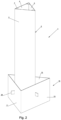
figure 1 shows an embodiment of the weak soil anchor device for anchoring a number of structures according to the invention, -
figure 2 shows a second embodiment of the weak soil anchor device according tofigure 1 , and -
figure 3 shows a third embodiment of the weak soil anchor device according to the present invention. - Referring first to
figures 1 and2 , there is shown a weaksoil anchor device 1 for anchoring a number of structures. The weaksoil anchor device 1 is shown in a vertical operating position. The weaksoil anchor device 1 consists of an elongate continuousopen box construction 2 with a triangular cross-section comprising afirst wall plate 3, second wall plate 4 and athird wall plate 5. An outer continuousopen box structure 10 with a smaller vertical extent than theinner box structure 2 and with a triangular cross-section consisting of a firstouter wall plate 11, secondouter wall plate 12 and thirdouter wall plate 13 is connected to the inner elongate continuousopen box structure 2 in a lower area of this. Thevertical center area 14 of the first, second and third outer wall surfaces is connected to, respectively, an outer edge area between the first andsecond wall surfaces 3, 4, second andthird wall surfaces 4, 5 and the third andfirst wall surfaces figure 1 ananchor bracket 20 is arranged respectively in each connecting area between the first and secondouter wall surfaces outer wall surfaces outer wall surfaces figure 2 theanchor bracket 20 is arranged respectively in each connecting area between theinner box structure 2 and theouter box structure 10.Anchor brackets 20 can also be arranged both in the corners of theouter box structure 10 and in the vertical center areas of theouter wall surfaces - Referring to
figure 3 a third embodiment of the weaksoil anchor device 1 is shown. The weaksoil anchor device 1 here comprises a further outer continuousopen box structure 25 with a triangular cross-section arranged externally of the outer continuousopen box structure 10. - The further outer
open box structure 25 comprises a firstfurther wall surface 26, a second furtherouter wall surface 27 and a third furtherouter wall surface 28. Avertical center area 29 of respectively the first, second and third furtherouter wall surfaces outer wall surfaces outer wall surface outer wall surface anchor bracket 20 is shown here arranged in respectively each of thevertical center areas 29 of respectively the first, second and third furtherouter wall surface - The weak
soil anchor device 1 according to the embodiment infigure 3 is further provided withbracing wall surfaces 30 extending from thevertical center area 14 of the first, second and thirdouter wall surfaces outer wall surfaces bracing wall surface 30 in this embodiment forms an angle within the range of respectively 60° and 120° with the first, second and third furtherouter wall surfaces outer box construction 25 in this embodiment has a smaller vertical extent than theouter box construction 10. It should be mentioned in this connection that the furtherouter box construction 25 does not necessarily needs to extend as deep as theouter box construction 10. The elongate inner continuousopen box structure 2, the outer continuousopen box structure 10 and the further outer continuousopen box structure 25 each have a cross section in the form of an equilateral triangle. Thebox constructions - The
anchor brackets 20 for anchor lines are fastened in the lower part of the weaksoil anchor device 1, where the total, resulting holding resistance from the adjacent ground masses acts based on the distribution of the ground resistance over the height of the anchor device. In this way, the weaksoil anchor device 1 will be able to utilize the horizontal ground resistance. - Depending on the required holding force and the local ground conditions, the
anchor device 1 can be formed by varying its geometry such as for example: - i) the length / height of the elongate continuous
open box structure 2 and the at least one outercontinuous box structure - ii) the cross-sectional shape of the continuous open box structures can be either an equilateral or a non-equilateral triangle,
- iii) the
anchor brackets 20 can be selected based on the distribution of the ground resistance over the height of the anchor device, whereby theanchor brackets 20 also can be arranged in the corners of theouter box structure 10 at a level directly above the furtherouter box structure 25. - The weak
soil anchor device 1 is as shown infigure 1 formed from straight plates which offer a simple and cost-effective manufacturing method. The anchor device can be manufactured and transported in a lying position. - The weak
soil anchor device 1 with the triangular box structure cross-section mean that the forces from the anchor line are distributed over the total height of theanchor device 1 to the surrounding weak soils by the inherent properties of the open box structure as a continuous beam. - The
anchor construction 1 is suitable for sharing of anchors, for example that a number of floats connect to the same anchor in a wind farm. In such a case theanchor device 1 must take loads from different directions. Theanchor device 1 is formed to take loads in three directions and further regarding the best holding capacity being achieved deeper in the ground, whereby the majority of the structure's material (steel, concrete) is placed in this area. The principles are that there is greater holding capacity deeper in the ground and that it is therefore effective to use more material deep down, while the upper part of theanchor device 1 is more to get theanchor device 1 pressed into the ground. The triangular-shapedbox constructions - As previously mentioned, the weak
soil anchor device 1 is formed with a view to being pressed down into the seabed by means of conventional frame equipment for piling. The frame equipment can, for example, be conventional pile hammers (drop weights or hydraulic hammers) or vibrohammers.Reinforcement plates 7 are arranged inside in an upper area of the corners of the innercontinuous box construction 2 to facilitate the use of piling equipment. The piling equipment can advantageously be mounted on theanchor device 1 on board a suitable installation vessel and lowered as a unit down to the seabed. Further driving of theanchor device 1 down into the weak soils takes place as for framing of free-standing piles. - After use, it will be possible to pull up the
anchor device 1 for reuse or use of a vibrohammer combined with an upward tensile force. - The weak
soil anchor device 1 is formed so that installation thereof does not have any limitations regarding soil profile. Different soil profiles will therefore not limit the use of the weaksoil anchor device 1. The soil profiles often show an increasing firmness with depth. The present weaksoil anchor device 1 is, as previously described, formed so that it uses as little construction material as possible in the upper soil layer, but uses more construction material in deeper and firmer soil layers. There is no need to use specially made auxiliary equipment beyond standard pile hammers for installation. Theanchor device 1 can be installed in an exact, predetermined position. - Finally, it should be mentioned that the previously known anchor solutions each have one or more of the properties and advantages that the
anchor device 1 according to the invention has, but the present weaksoil anchor device 1 enables all these properties to be integrated in a new anchoring concept.
Claims (14)
- A weak soil anchor device (1) for anchoring one or more structures,
wherein said device seen in a vertical operating position comprises:an elongate inner continuous open box construction (2) with a triangular cross-section comprising a first wall surface (3), second wall surface (4) and third wall surface (5),an outer continuous open box structure (10) with a smaller vertical extent than the inner box structure (2) and with a triangular cross-section consisting of a first outer wall surface (11), second outer wall surface (12) and third outer wall surface (13), where the vertical center area (14) of the first, second and third outer wall surfaces is connected to the inner elongate continuous open box structure (2) in a lower region of respectively an outer edge area between the first and second wall surface (3, 4), second and third wall surface (4, 5) and the third and first wall surface (5, 3), andanchor brackets (20) are arranged in a lower outer area of the weak soil anchor device (1),whereby the weak soil anchor device comprising the inner and outer box structure (2, 10) is lowered in use into the weak soils to a desired depth. - Weak soil anchor device (1) according to claim 1, characterized in that the anchor brackets (20) are arranged respectively in each connecting area between the inner box structure (2) and the outer box structure (10).
- Weak soil anchor device (1) according to claim 1, characterized in that the anchor brackets (20) are arranged respectively in each connecting area between the first and second outer wall surfaces (11, 12), second and third outer wall surfaces (12, 13) and third and first outer wall surfaces (13, 11).
- Weak soil anchor device (1) according to claim 1, characterized in that it further comprises a further outer continuous open box structure (25) with a triangular cross-section arranged externally of the outer continuous open box structure (10), the further outer open box structure (25) comprising a first further outer wall surface (26), a second further outer wall surface (27) and a third further outer wall surface (28), where a vertical center area (29) of respectively the first, second and third outer wall surface (26, 27, 28) is connected to respectively a lower connection area between the first and second outer wall surface (11, 12), second and third outer wall surface (12, 13), third and first outer wall surface (13, 11), and
the anchor brackets (20) are arranged respectively in each of the vertical center areas (29) of respectively the first, second and third further outer wall surfaces (26, 27, 28). - Weak soil anchor device (1) according to claim 4, characterized in that bracing wall surfaces (30) extend from the vertical center area (14) of the first, second and third outer wall surfaces (11, 12, 13) to respectively the first, second and third further outer wall surfaces (26, 27, 28).
- Weak soil anchor device (1) according to claim 5, characterized in that the bracing wall surfaces (30) form an angle within the range of respectively 60° and 120° with the first, second and third further outer wall surfaces (26, 27, 28).
- Weak soil anchor device (1) according to claim 4, 5 or 6, characterized in that the further outer box structure (25) has a smaller vertical extent than the outer box structure (10).
- Weak soil anchor device (1) according to any one of the preceding claims, characterized in that the triangular-shaped cross-section of the box structures (2, 10, 25) is an equilateral triangle.
- Weak soil anchor device (1) according to claims 1-7, characterized in that the triangular cross-section of the box structures (2, 10, 25) is a non-equilateral triangle.
- Weak soil anchor device (1) according to any one of the preceding claims, characterized in that the anchor brackets (20) are arranged in the lower area of the weak soil anchor device (1) where the total, resulting holding resistance from the adjacent soil masses seems to be selected based on the distribution of the ground resistance over the height of the anchor device.
- Weak soil anchor device (1) according to any one of the preceding claims, characterized in that the weak soil anchor device (1) is dimensioned depending on holding force and ground conditions in that the geometry of the anchor device (1) is varied with respect to: the vertical extent of the elongate box structure (2), the at least one outer box structure (10, 25), the triangular cross-section of the box structures, and the placement of the anchor brackets (20) is selected on the basis of the distribution of the ground resistance over the length of the anchor device (1).
- Weak soil anchor device (1) according to any one of the preceding claims, characterized in that the weak soil anchor device (1) is made of steel.
- A method of arranging an anchoring in weak soils for anchoring one or more structures, where a weak soil anchor device (1) according to any one of the preceding claims 1 to 12 is used, comprising:the weak soil anchor device (1) is fitted with anchor lines,the weak soil anchor device (1) with fitted anchor lines is lowered with its lower end area towards the weak soils, andthe weak soil anchor device (1) is pressed into the weak soils with conventional frame equipment for piling or by using a vibrohammer.
- A method according to claim 13, characterized in that it comprises the further features:
the weak soil anchor device (1) is released and pulled up from the weak soils by using a vibrohammer combined with an upward pulling force.
Applications Claiming Priority (3)
| Application Number | Priority Date | Filing Date | Title |
|---|---|---|---|
| NO20190693A NO345713B1 (en) | 2019-06-03 | 2019-06-03 | Loose material anchor device and method for arranging an anchorage in loose materials |
| NO20191069A NO345374B1 (en) | 2019-06-03 | 2019-09-05 | Loose mass anchoring device for anchoring one or more structures as well as method for arranging an anchorage in loose masses |
| PCT/NO2020/050220 WO2021045626A1 (en) | 2019-06-03 | 2020-08-28 | Weak soil anchor device to anchor one or several structures and method to arrange an anchor in weak soil |
Publications (4)
| Publication Number | Publication Date |
|---|---|
| EP4025491A1 EP4025491A1 (en) | 2022-07-13 |
| EP4025491A4 EP4025491A4 (en) | 2023-10-04 |
| EP4025491C0 EP4025491C0 (en) | 2025-06-11 |
| EP4025491B1 true EP4025491B1 (en) | 2025-06-11 |
Family
ID=73652234
Family Applications (2)
| Application Number | Title | Priority Date | Filing Date |
|---|---|---|---|
| EP20818726.0A Active EP3976459B1 (en) | 2019-06-03 | 2020-05-26 | Unconsolidated material anchor device and process for arranging an anchor pile in unconsolidated materials |
| EP20860825.7A Active EP4025491B1 (en) | 2019-06-03 | 2020-08-28 | Weak soil anchor device to anchor one or several structures and method to arrange an anchor in weak soil |
Family Applications Before (1)
| Application Number | Title | Priority Date | Filing Date |
|---|---|---|---|
| EP20818726.0A Active EP3976459B1 (en) | 2019-06-03 | 2020-05-26 | Unconsolidated material anchor device and process for arranging an anchor pile in unconsolidated materials |
Country Status (6)
| Country | Link |
|---|---|
| US (1) | US12345012B2 (en) |
| EP (2) | EP3976459B1 (en) |
| JP (1) | JP7644097B2 (en) |
| KR (1) | KR102903424B1 (en) |
| NO (2) | NO345713B1 (en) |
| WO (2) | WO2020246893A1 (en) |
Families Citing this family (2)
| Publication number | Priority date | Publication date | Assignee | Title |
|---|---|---|---|---|
| EP4212672A1 (en) * | 2022-01-14 | 2023-07-19 | Corpower Ocean AB | Pile arrangement for vibration driving and method of vibration driving |
| EP4478517A4 (en) | 2022-07-07 | 2025-10-22 | Lg Energy Solution Ltd | SEPARATOR FOR ELECTROCHEMICAL DEVICES AND METHOD FOR MANUFACTURING SAME |
Family Cites Families (20)
| Publication number | Priority date | Publication date | Assignee | Title |
|---|---|---|---|---|
| US1133496A (en) * | 1914-04-18 | 1915-03-30 | Clifton F Noakes | Post-anchor. |
| SE343353B (en) * | 1967-12-29 | 1972-03-06 | Zaklady Remontu Maszyn Budowla | |
| US3850128A (en) * | 1973-07-16 | 1974-11-26 | Ocean Science & Eng | Vibratory anchor |
| SE8206927L (en) * | 1982-12-03 | 1984-06-04 | Accurat Teknik Ab | PROCEDURE AND DEVICE FOR FITTING THE POST OR FOUNDATION |
| FR2537536B1 (en) * | 1982-12-08 | 1986-05-16 | Doris Dev Richesse Sous Marine | DEAD-BODY ANCHORING DEVICE ON FURNISHED SEA-BASES |
| EP0157033B1 (en) * | 1984-04-06 | 1988-09-28 | Johan Hasiholan Simanjuntak | Driven pile with transverse broadening in situ |
| DE3507269A1 (en) * | 1984-09-22 | 1986-05-22 | Gebr. Sträb GmbH & Co Stanz- und Prägewerk, 7317 Wendlingen | Ground fixing means |
| GB8719577D0 (en) * | 1987-08-19 | 1987-09-23 | Anchortech Ltd | Pile |
| JPH0781269B2 (en) * | 1992-07-21 | 1995-08-30 | アーステック株式会社 | Friction / bearing type ground anchor method and bearing body for ground anchor |
| SE508192C2 (en) * | 1993-11-19 | 1998-09-14 | Goete Lindberg | Ground anchoring device with associated post |
| NO307993B1 (en) * | 1998-03-10 | 2000-07-03 | Umoe Anchor Contracting As | A method of penetrating a plate anchor into a seabed, a plate anchor for use in the method, and a device by a vessel for launching a plate anchor according to the method |
| US6223671B1 (en) * | 1998-07-29 | 2001-05-01 | Philip Head | Mooring system |
| CA2513534A1 (en) * | 2003-03-04 | 2004-09-16 | Exxonmobil Upstream Research Company | Pile anchor with external vanes |
| JP2011021453A (en) * | 2009-07-16 | 2011-02-03 | Shinbee Kishimoto | Invention related to pile shot into seabed utilizing rocket thrust to moor equipment installed in sea |
| KR20110077143A (en) * | 2009-12-30 | 2011-07-07 | 주식회사 포스코 | Steel pipe pile tip reinforcement and steel pipe pile assembly |
| US10352013B2 (en) * | 2011-11-15 | 2019-07-16 | Stephen Kelleher | Ground mounting assembly |
| KR20150115051A (en) * | 2014-04-02 | 2015-10-14 | 대우조선해양 주식회사 | Mooring device of floating construction, mooring method therefor, and floating construction |
| KR101722198B1 (en) * | 2015-07-24 | 2017-03-31 | 삼성중공업 주식회사 | Anchoring apparatus |
| KR101722190B1 (en) * | 2015-07-29 | 2017-03-31 | 삼성중공업 주식회사 | Anchoring apparatus |
| KR101722185B1 (en) * | 2015-08-11 | 2017-03-31 | 삼성중공업 주식회사 | Anchoring apparatus |
-
2019
- 2019-06-03 NO NO20190693A patent/NO345713B1/en unknown
- 2019-09-05 NO NO20191069A patent/NO345374B1/en unknown
-
2020
- 2020-05-26 EP EP20818726.0A patent/EP3976459B1/en active Active
- 2020-05-26 WO PCT/NO2020/050136 patent/WO2020246893A1/en not_active Ceased
- 2020-08-28 JP JP2022515077A patent/JP7644097B2/en active Active
- 2020-08-28 US US17/640,088 patent/US12345012B2/en active Active
- 2020-08-28 KR KR1020227011112A patent/KR102903424B1/en active Active
- 2020-08-28 EP EP20860825.7A patent/EP4025491B1/en active Active
- 2020-08-28 WO PCT/NO2020/050220 patent/WO2021045626A1/en not_active Ceased
Also Published As
| Publication number | Publication date |
|---|---|
| NO345374B1 (en) | 2021-01-11 |
| WO2021045626A1 (en) | 2021-03-11 |
| KR20220083685A (en) | 2022-06-20 |
| CA3152816A1 (en) | 2021-03-11 |
| EP4025491C0 (en) | 2025-06-11 |
| JP7644097B2 (en) | 2025-03-11 |
| WO2020246893A1 (en) | 2020-12-10 |
| EP4025491A4 (en) | 2023-10-04 |
| EP3976459A4 (en) | 2023-07-05 |
| EP3976459B1 (en) | 2025-06-25 |
| EP4025491A1 (en) | 2022-07-13 |
| EP3976459C0 (en) | 2025-06-25 |
| NO20190693A1 (en) | 2020-12-04 |
| EP3976459A1 (en) | 2022-04-06 |
| JP2022547147A (en) | 2022-11-10 |
| NO20191069A1 (en) | 2020-12-04 |
| NO345713B1 (en) | 2021-06-28 |
| KR102903424B1 (en) | 2025-12-23 |
| US12345012B2 (en) | 2025-07-01 |
| US20220298739A1 (en) | 2022-09-22 |
Similar Documents
| Publication | Publication Date | Title |
|---|---|---|
| EP3695055B1 (en) | Offshore wind energy installation foundation system | |
| US9428876B2 (en) | Multi-suction-pile anchor and flat plate anchor having suction piles | |
| US9771700B2 (en) | Structures for offshore installations | |
| JP6776505B2 (en) | How to build the foundation of offshore facilities, the foundation of offshore facilities and the foundation of offshore facilities | |
| US20170167101A1 (en) | Pile for an offshore monopile type foundation structure | |
| US12345012B2 (en) | Weak soil anchor device to anchor one or several structures and method to arrange an anchor in weak soil | |
| JP5150596B2 (en) | Anchor device and anchor construction method | |
| CA3152816C (en) | Weak soil anchor device to anchor one or several structures and method to arrange an anchor in weak soil | |
| JP6542036B2 (en) | Pile foundation structure | |
| CN215715257U (en) | Novel plate-barrel gravity anchor | |
| CN114351690A (en) | Hollow sandwich steel pipe concrete pile and construction method thereof | |
| KR20090112426A (en) | Offshore pile reinforcement using bucket foundation | |
| KR20250032133A (en) | Suction pile anchor having initial penetration meams | |
| KR20130028312A (en) | Offshore structure having making part for lifting power and structure method thereof | |
| KR102177844B1 (en) | guide anchor for constructing file and construction method | |
| CN212388543U (en) | On-site fixing device for ultra-high cable wind rope | |
| EP2971372B1 (en) | Axial capacity enhanced pile | |
| EP0312198B1 (en) | Pile, in particular an anchor pile | |
| US5527136A (en) | Mono-tripod platform | |
| JP2026514012A (en) | System and installation method for forming anchor points for floating bodies for offshore wind turbines | |
| EP4667661A1 (en) | An offshore wind turbine foundation and a method for installing an offshore wind turbine foundation | |
| KR101237986B1 (en) | Structure of offshore structure and construction method thereof | |
| JPH06287965A (en) | Foundation for soft ground and construction method for foundation in soft ground | |
| JP2000314133A (en) | Horizontal load-bearing pile and its arrangement method | |
| KR101735283B1 (en) | A raft structure and Method for installing suction pile using the same |
Legal Events
| Date | Code | Title | Description |
|---|---|---|---|
| STAA | Information on the status of an ep patent application or granted ep patent |
Free format text: STATUS: THE INTERNATIONAL PUBLICATION HAS BEEN MADE |
|
| PUAI | Public reference made under article 153(3) epc to a published international application that has entered the european phase |
Free format text: ORIGINAL CODE: 0009012 |
|
| STAA | Information on the status of an ep patent application or granted ep patent |
Free format text: STATUS: REQUEST FOR EXAMINATION WAS MADE |
|
| 17P | Request for examination filed |
Effective date: 20220224 |
|
| AK | Designated contracting states |
Kind code of ref document: A1 Designated state(s): AL AT BE BG CH CY CZ DE DK EE ES FI FR GB GR HR HU IE IS IT LI LT LU LV MC MK MT NL NO PL PT RO RS SE SI SK SM TR |
|
| DAV | Request for validation of the european patent (deleted) | ||
| DAX | Request for extension of the european patent (deleted) | ||
| A4 | Supplementary search report drawn up and despatched |
Effective date: 20230906 |
|
| RIC1 | Information provided on ipc code assigned before grant |
Ipc: E02D 27/52 20060101ALI20230831BHEP Ipc: E02D 5/54 20060101ALI20230831BHEP Ipc: B63B 21/26 20060101AFI20230831BHEP |
|
| STAA | Information on the status of an ep patent application or granted ep patent |
Free format text: STATUS: THE APPLICATION IS DEEMED TO BE WITHDRAWN |
|
| 18D | Application deemed to be withdrawn |
Effective date: 20240409 |
|
| STAA | Information on the status of an ep patent application or granted ep patent |
Free format text: STATUS: REQUEST FOR EXAMINATION WAS MADE |
|
| D18D | Application deemed to be withdrawn (deleted) | ||
| GRAP | Despatch of communication of intention to grant a patent |
Free format text: ORIGINAL CODE: EPIDOSNIGR1 |
|
| STAA | Information on the status of an ep patent application or granted ep patent |
Free format text: STATUS: GRANT OF PATENT IS INTENDED |
|
| INTG | Intention to grant announced |
Effective date: 20250206 |
|
| GRAS | Grant fee paid |
Free format text: ORIGINAL CODE: EPIDOSNIGR3 |
|
| GRAA | (expected) grant |
Free format text: ORIGINAL CODE: 0009210 |
|
| STAA | Information on the status of an ep patent application or granted ep patent |
Free format text: STATUS: THE PATENT HAS BEEN GRANTED |
|
| AK | Designated contracting states |
Kind code of ref document: B1 Designated state(s): AL AT BE BG CH CY CZ DE DK EE ES FI FR GB GR HR HU IE IS IT LI LT LU LV MC MK MT NL NO PL PT RO RS SE SI SK SM TR |
|
| REG | Reference to a national code |
Ref country code: CH Ref legal event code: EP |
|
| REG | Reference to a national code |
Ref country code: IE Ref legal event code: FG4D |
|
| REG | Reference to a national code |
Ref country code: DE Ref legal event code: R096 Ref document number: 602020052737 Country of ref document: DE |
|
| U01 | Request for unitary effect filed |
Effective date: 20250702 |
|
| U07 | Unitary effect registered |
Designated state(s): AT BE BG DE DK EE FI FR IT LT LU LV MT NL PT RO SE SI Effective date: 20250709 |
|
| PG25 | Lapsed in a contracting state [announced via postgrant information from national office to epo] |
Ref country code: ES Free format text: LAPSE BECAUSE OF FAILURE TO SUBMIT A TRANSLATION OF THE DESCRIPTION OR TO PAY THE FEE WITHIN THE PRESCRIBED TIME-LIMIT Effective date: 20250611 |
|
| PG25 | Lapsed in a contracting state [announced via postgrant information from national office to epo] |
Ref country code: NO Free format text: LAPSE BECAUSE OF FAILURE TO SUBMIT A TRANSLATION OF THE DESCRIPTION OR TO PAY THE FEE WITHIN THE PRESCRIBED TIME-LIMIT Effective date: 20250911 Ref country code: GR Free format text: LAPSE BECAUSE OF FAILURE TO SUBMIT A TRANSLATION OF THE DESCRIPTION OR TO PAY THE FEE WITHIN THE PRESCRIBED TIME-LIMIT Effective date: 20250912 |
|
| PGFP | Annual fee paid to national office [announced via postgrant information from national office to epo] |
Ref country code: GB Payment date: 20250916 Year of fee payment: 6 |
|
| PG25 | Lapsed in a contracting state [announced via postgrant information from national office to epo] |
Ref country code: HR Free format text: LAPSE BECAUSE OF FAILURE TO SUBMIT A TRANSLATION OF THE DESCRIPTION OR TO PAY THE FEE WITHIN THE PRESCRIBED TIME-LIMIT Effective date: 20250611 |
|
| PG25 | Lapsed in a contracting state [announced via postgrant information from national office to epo] |
Ref country code: RS Free format text: LAPSE BECAUSE OF FAILURE TO SUBMIT A TRANSLATION OF THE DESCRIPTION OR TO PAY THE FEE WITHIN THE PRESCRIBED TIME-LIMIT Effective date: 20250911 |
|
| U20 | Renewal fee for the european patent with unitary effect paid |
Year of fee payment: 6 Effective date: 20250916 |
|
| PG25 | Lapsed in a contracting state [announced via postgrant information from national office to epo] |
Ref country code: IS Free format text: LAPSE BECAUSE OF FAILURE TO SUBMIT A TRANSLATION OF THE DESCRIPTION OR TO PAY THE FEE WITHIN THE PRESCRIBED TIME-LIMIT Effective date: 20251011 |
|
| PG25 | Lapsed in a contracting state [announced via postgrant information from national office to epo] |
Ref country code: SM Free format text: LAPSE BECAUSE OF FAILURE TO SUBMIT A TRANSLATION OF THE DESCRIPTION OR TO PAY THE FEE WITHIN THE PRESCRIBED TIME-LIMIT Effective date: 20250611 |
|
| PG25 | Lapsed in a contracting state [announced via postgrant information from national office to epo] |
Ref country code: CZ Free format text: LAPSE BECAUSE OF FAILURE TO SUBMIT A TRANSLATION OF THE DESCRIPTION OR TO PAY THE FEE WITHIN THE PRESCRIBED TIME-LIMIT Effective date: 20250611 |
|
| PG25 | Lapsed in a contracting state [announced via postgrant information from national office to epo] |
Ref country code: PL Free format text: LAPSE BECAUSE OF FAILURE TO SUBMIT A TRANSLATION OF THE DESCRIPTION OR TO PAY THE FEE WITHIN THE PRESCRIBED TIME-LIMIT Effective date: 20250611 |
|
| PG25 | Lapsed in a contracting state [announced via postgrant information from national office to epo] |
Ref country code: SK Free format text: LAPSE BECAUSE OF FAILURE TO SUBMIT A TRANSLATION OF THE DESCRIPTION OR TO PAY THE FEE WITHIN THE PRESCRIBED TIME-LIMIT Effective date: 20250611 |
|
| REG | Reference to a national code |
Ref country code: CH Ref legal event code: H13 Free format text: ST27 STATUS EVENT CODE: U-0-0-H10-H13 (AS PROVIDED BY THE NATIONAL OFFICE) Effective date: 20260324 |
|
| PG25 | Lapsed in a contracting state [announced via postgrant information from national office to epo] |
Ref country code: MC Free format text: LAPSE BECAUSE OF FAILURE TO SUBMIT A TRANSLATION OF THE DESCRIPTION OR TO PAY THE FEE WITHIN THE PRESCRIBED TIME-LIMIT Effective date: 20250611 |
|
| PLBE | No opposition filed within time limit |
Free format text: ORIGINAL CODE: 0009261 |
|
| STAA | Information on the status of an ep patent application or granted ep patent |
Free format text: STATUS: NO OPPOSITION FILED WITHIN TIME LIMIT |
|
| PG25 | Lapsed in a contracting state [announced via postgrant information from national office to epo] |
Ref country code: CH Free format text: LAPSE BECAUSE OF NON-PAYMENT OF DUE FEES Effective date: 20250831 |
|
| REG | Reference to a national code |
Ref country code: CH Ref legal event code: L10 Free format text: ST27 STATUS EVENT CODE: U-0-0-L10-L00 (AS PROVIDED BY THE NATIONAL OFFICE) Effective date: 20260423 |