EP4025026A2 - Efficient and robust system design and control method using thermoelectric cooling - Google Patents
Efficient and robust system design and control method using thermoelectric cooling Download PDFInfo
- Publication number
- EP4025026A2 EP4025026A2 EP22164019.6A EP22164019A EP4025026A2 EP 4025026 A2 EP4025026 A2 EP 4025026A2 EP 22164019 A EP22164019 A EP 22164019A EP 4025026 A2 EP4025026 A2 EP 4025026A2
- Authority
- EP
- European Patent Office
- Prior art keywords
- tec
- cooling
- pump
- cooling system
- current
- Prior art date
- Legal status (The legal status is an assumption and is not a legal conclusion. Google has not performed a legal analysis and makes no representation as to the accuracy of the status listed.)
- Withdrawn
Links
Images



Classifications
-
- H—ELECTRICITY
- H05—ELECTRIC TECHNIQUES NOT OTHERWISE PROVIDED FOR
- H05K—PRINTED CIRCUITS; CASINGS OR CONSTRUCTIONAL DETAILS OF ELECTRIC APPARATUS; MANUFACTURE OF ASSEMBLAGES OF ELECTRICAL COMPONENTS
- H05K7/00—Constructional details common to different types of electric apparatus
- H05K7/20—Modifications to facilitate cooling, ventilating, or heating
- H05K7/20709—Modifications to facilitate cooling, ventilating, or heating for server racks or cabinets; for data centers, e.g. 19-inch computer racks
- H05K7/20836—Thermal management, e.g. server temperature control
-
- G—PHYSICS
- G06—COMPUTING OR CALCULATING; COUNTING
- G06F—ELECTRIC DIGITAL DATA PROCESSING
- G06F1/00—Details not covered by groups G06F3/00 - G06F13/00 and G06F21/00
- G06F1/16—Constructional details or arrangements
- G06F1/20—Cooling means
-
- G—PHYSICS
- G05—CONTROLLING; REGULATING
- G05B—CONTROL OR REGULATING SYSTEMS IN GENERAL; FUNCTIONAL ELEMENTS OF SUCH SYSTEMS; MONITORING OR TESTING ARRANGEMENTS FOR SUCH SYSTEMS OR ELEMENTS
- G05B15/00—Systems controlled by a computer
- G05B15/02—Systems controlled by a computer electric
-
- G—PHYSICS
- G06—COMPUTING OR CALCULATING; COUNTING
- G06F—ELECTRIC DIGITAL DATA PROCESSING
- G06F1/00—Details not covered by groups G06F3/00 - G06F13/00 and G06F21/00
- G06F1/26—Power supply means, e.g. regulation thereof
- G06F1/28—Supervision thereof, e.g. detecting power-supply failure by out of limits supervision
-
- G—PHYSICS
- G06—COMPUTING OR CALCULATING; COUNTING
- G06F—ELECTRIC DIGITAL DATA PROCESSING
- G06F1/00—Details not covered by groups G06F3/00 - G06F13/00 and G06F21/00
- G06F1/26—Power supply means, e.g. regulation thereof
- G06F1/32—Means for saving power
- G06F1/3203—Power management, i.e. event-based initiation of a power-saving mode
-
- H—ELECTRICITY
- H05—ELECTRIC TECHNIQUES NOT OTHERWISE PROVIDED FOR
- H05K—PRINTED CIRCUITS; CASINGS OR CONSTRUCTIONAL DETAILS OF ELECTRIC APPARATUS; MANUFACTURE OF ASSEMBLAGES OF ELECTRICAL COMPONENTS
- H05K7/00—Constructional details common to different types of electric apparatus
- H05K7/20—Modifications to facilitate cooling, ventilating, or heating
- H05K7/20218—Modifications to facilitate cooling, ventilating, or heating using a liquid coolant without phase change in electronic enclosures
- H05K7/20236—Modifications to facilitate cooling, ventilating, or heating using a liquid coolant without phase change in electronic enclosures by immersion
-
- H—ELECTRICITY
- H05—ELECTRIC TECHNIQUES NOT OTHERWISE PROVIDED FOR
- H05K—PRINTED CIRCUITS; CASINGS OR CONSTRUCTIONAL DETAILS OF ELECTRIC APPARATUS; MANUFACTURE OF ASSEMBLAGES OF ELECTRICAL COMPONENTS
- H05K7/00—Constructional details common to different types of electric apparatus
- H05K7/20—Modifications to facilitate cooling, ventilating, or heating
- H05K7/20218—Modifications to facilitate cooling, ventilating, or heating using a liquid coolant without phase change in electronic enclosures
- H05K7/20272—Accessories for moving fluid, for expanding fluid, for connecting fluid conduits, for distributing fluid, for removing gas or for preventing leakage, e.g. pumps, tanks or manifolds
-
- H—ELECTRICITY
- H05—ELECTRIC TECHNIQUES NOT OTHERWISE PROVIDED FOR
- H05K—PRINTED CIRCUITS; CASINGS OR CONSTRUCTIONAL DETAILS OF ELECTRIC APPARATUS; MANUFACTURE OF ASSEMBLAGES OF ELECTRICAL COMPONENTS
- H05K7/00—Constructional details common to different types of electric apparatus
- H05K7/20—Modifications to facilitate cooling, ventilating, or heating
- H05K7/20709—Modifications to facilitate cooling, ventilating, or heating for server racks or cabinets; for data centers, e.g. 19-inch computer racks
- H05K7/20763—Liquid cooling without phase change
-
- H—ELECTRICITY
- H05—ELECTRIC TECHNIQUES NOT OTHERWISE PROVIDED FOR
- H05K—PRINTED CIRCUITS; CASINGS OR CONSTRUCTIONAL DETAILS OF ELECTRIC APPARATUS; MANUFACTURE OF ASSEMBLAGES OF ELECTRICAL COMPONENTS
- H05K7/00—Constructional details common to different types of electric apparatus
- H05K7/20—Modifications to facilitate cooling, ventilating, or heating
- H05K7/20709—Modifications to facilitate cooling, ventilating, or heating for server racks or cabinets; for data centers, e.g. 19-inch computer racks
- H05K7/20763—Liquid cooling without phase change
- H05K7/20772—Liquid cooling without phase change within server blades for removing heat from heat source
-
- H—ELECTRICITY
- H05—ELECTRIC TECHNIQUES NOT OTHERWISE PROVIDED FOR
- H05K—PRINTED CIRCUITS; CASINGS OR CONSTRUCTIONAL DETAILS OF ELECTRIC APPARATUS; MANUFACTURE OF ASSEMBLAGES OF ELECTRICAL COMPONENTS
- H05K7/00—Constructional details common to different types of electric apparatus
- H05K7/20—Modifications to facilitate cooling, ventilating, or heating
- H05K7/20709—Modifications to facilitate cooling, ventilating, or heating for server racks or cabinets; for data centers, e.g. 19-inch computer racks
- H05K7/20763—Liquid cooling without phase change
- H05K7/20781—Liquid cooling without phase change within cabinets for removing heat from server blades
-
- H—ELECTRICITY
- H10—SEMICONDUCTOR DEVICES; ELECTRIC SOLID-STATE DEVICES NOT OTHERWISE PROVIDED FOR
- H10W—GENERIC PACKAGES, INTERCONNECTIONS, CONNECTORS OR OTHER CONSTRUCTIONAL DETAILS OF DEVICES COVERED BY CLASS H10
- H10W40/00—Arrangements for thermal protection or thermal control
- H10W40/40—Arrangements for thermal protection or thermal control involving heat exchange by flowing fluids
- H10W40/47—Arrangements for thermal protection or thermal control involving heat exchange by flowing fluids by flowing liquids, e.g. forced water cooling
-
- G—PHYSICS
- G06—COMPUTING OR CALCULATING; COUNTING
- G06F—ELECTRIC DIGITAL DATA PROCESSING
- G06F1/00—Details not covered by groups G06F3/00 - G06F13/00 and G06F21/00
- G06F1/16—Constructional details or arrangements
- G06F1/20—Cooling means
- G06F1/206—Cooling means comprising thermal management
-
- G—PHYSICS
- G06—COMPUTING OR CALCULATING; COUNTING
- G06F—ELECTRIC DIGITAL DATA PROCESSING
- G06F2200/00—Indexing scheme relating to G06F1/04 - G06F1/32
- G06F2200/20—Indexing scheme relating to G06F1/20
- G06F2200/201—Cooling arrangements using cooling fluid
-
- H—ELECTRICITY
- H05—ELECTRIC TECHNIQUES NOT OTHERWISE PROVIDED FOR
- H05K—PRINTED CIRCUITS; CASINGS OR CONSTRUCTIONAL DETAILS OF ELECTRIC APPARATUS; MANUFACTURE OF ASSEMBLAGES OF ELECTRICAL COMPONENTS
- H05K7/00—Constructional details common to different types of electric apparatus
- H05K7/20—Modifications to facilitate cooling, ventilating, or heating
- H05K7/20218—Modifications to facilitate cooling, ventilating, or heating using a liquid coolant without phase change in electronic enclosures
- H05K7/20281—Thermal management, e.g. liquid flow control
-
- H—ELECTRICITY
- H10—SEMICONDUCTOR DEVICES; ELECTRIC SOLID-STATE DEVICES NOT OTHERWISE PROVIDED FOR
- H10N—ELECTRIC SOLID-STATE DEVICES NOT OTHERWISE PROVIDED FOR
- H10N10/00—Thermoelectric devices comprising a junction of dissimilar materials, i.e. devices exhibiting Seebeck or Peltier effects
-
- H—ELECTRICITY
- H10—SEMICONDUCTOR DEVICES; ELECTRIC SOLID-STATE DEVICES NOT OTHERWISE PROVIDED FOR
- H10W—GENERIC PACKAGES, INTERCONNECTIONS, CONNECTORS OR OTHER CONSTRUCTIONAL DETAILS OF DEVICES COVERED BY CLASS H10
- H10W40/00—Arrangements for thermal protection or thermal control
- H10W40/20—Arrangements for cooling
- H10W40/28—Arrangements for cooling comprising Peltier coolers
-
- Y—GENERAL TAGGING OF NEW TECHNOLOGICAL DEVELOPMENTS; GENERAL TAGGING OF CROSS-SECTIONAL TECHNOLOGIES SPANNING OVER SEVERAL SECTIONS OF THE IPC; TECHNICAL SUBJECTS COVERED BY FORMER USPC CROSS-REFERENCE ART COLLECTIONS [XRACs] AND DIGESTS
- Y02—TECHNOLOGIES OR APPLICATIONS FOR MITIGATION OR ADAPTATION AGAINST CLIMATE CHANGE
- Y02D—CLIMATE CHANGE MITIGATION TECHNOLOGIES IN INFORMATION AND COMMUNICATION TECHNOLOGIES [ICT], I.E. INFORMATION AND COMMUNICATION TECHNOLOGIES AIMING AT THE REDUCTION OF THEIR OWN ENERGY USE
- Y02D10/00—Energy efficient computing, e.g. low power processors, power management or thermal management
Definitions
- Embodiments of the present invention relate generally to data centers. More particularly, embodiments of the invention relate an efficient and robust system design and control method using thermoelectric cooling.
- Heat removal is a prominent factor in a computer system and data center design.
- the number of high performance electronics components such as high performance processors packaged inside servers have steadily increased, thereby increasing the amount of heat generated and dissipated during the ordinary operations of the servers.
- the reliability of servers used within a data center decreases if the environment in which they operate is permitted to increase in temperature over time. Maintaining a proper thermal environment is critical for normal operations of these servers in data centers, as well as the server performance and lifetime. It requires more effective and efficient heat removal solutions especially in the cases of cooling these high performance servers.
- Immersion cooling technology has brought many attentions recently. Many efforts are focusing on the fluid selection, information technology (IT) side design, material compatibilities, test and verification, and so on. Most of the solutions utilize existing cooling infrastructure (cooling water/chilled water) or system. In some of the solutions, a coolant distribution unit (CDU) is used to form an external cooling loop and an internal immersion cooling fluid loop. The external cooling loop can be adapted to any type of existing data center cooling infrastructures. These solutions may not fully utilize the advantages of immersion cooling.
- CDU coolant distribution unit
- Thermoelectric cooling (TEC) technology also has also been spotlighted recently.
- Thermoelectric coolers have their own COP (coefficient of performance) optimization methods.
- the maximized COP is the lowest power overhead for a specific cooling power capacity of a TEC device.
- the IT equipment When the fluid pump fails, the IT equipment performs certain operations before shutting down. These operations include backing up data in memory or transferring work load. At the same time, the dielectric fluid temperature continues increasing during these operations. A sufficiently large time window before shutting down IT equipment is essential to have a more robust immersion cooling system.
- Embodiments of the present disclosure seek to solve at least one of the problems existing in the related art to at least some extent.
- a cooling system including: a board management controller (BMC) configured to determine a first power value representing a power consumed by an electronic device, perform a lookup operation in a control lookup table based on the first power value, and determine a first thermoelectric cooling (TEC) current and a first pump speed based on the lookup operation; a TEC controller to control a TEC device attached to the electronic device to cause the first TEC current to flow within the TEC device; and a cooling distribution unit (CDU) controller to configure a pump speed of a fluid pump of a CDU according to the first pump speed, wherein the CDU is to provide liquid cooling to the electronic device.
- BMC board management controller
- TEC thermoelectric cooling
- CDU cooling distribution unit
- control lookup table includes a plurality of entries, wherein each entry maps a particular power value to an optimal TEC current and an optimal pump speed corresponding to that particular power value.
- control lookup table is generated based on prior operational statistics data of a plurality of cooling systems, including determining optimal TEC currents and pump speeds for providing liquid cooling such that power consumption by each cooling system reaches minimum.
- the cooling system further includes an immersion tank to contain the electronic device and the TEC device submerged into the cooling fluid contained therein.
- the CDU is located outside of the immersion tank.
- the BMC is configured to monitor operations of the electronic device for a predetermined period of time to obtain the first power value.
- the first TEC current and the first pump speed are determined based on the lookup operation, such that power consumption of the cooling system reaches minimum while satisfying a thermal requirement of the electronic device.
- the TEC controller is configured to cause a TEC current to flow in a first direction within the TEC device when a fluid temperature of a fluid of the liquid cooling drops below a first predetermined temperature threshold, which causes the TEC device to operate in a heating mode.
- the TEC controller is configured to cause the TEC current to flow in a second direction within the TEC device when the fluid temperature rises above a second predetermined temperature threshold, which causes the TEC device to operate in a cooling mode.
- the cooling system has a cooling power consumption consisting of the TEC power overhead and a pump power.
- an electronic rack of a data center including: one or more electronic devices operating as one or more servers; and the cooling system as defined in any of the above embodiments, coupled to the one or more electronic devices.
- a method for providing liquid cooling including: determining a first power value representing a power consumed by an electronic device; performing a lookup operation in a control lookup table based on the first power value; determining a first thermoelectric cooling (TEC) current and a first pump speed based on the lookup operation; causing the first TEC current to flow within the TEC device; and configuring a pump speed of a fluid pump of a CDU according to the first pump speed, wherein the CDU is to provide liquid cooling to the electronic device.
- TEC thermoelectric cooling
- control lookup table includes a plurality of entries, wherein each entry maps a particular power value to an optimal TEC current and an optimal pump speed corresponding to that particular power value.
- control lookup table is generated based on prior operational statistics data of a plurality of cooling systems, including determining optimal TEC currents and pump speeds for providing liquid cooling such that power consumption by each cooling system reaches minimum.
- IT Hardware is a critical market for many reasons: it plays a crucial role in business competitiveness, service quality and availability, and also plays a significant role in the infrastructure TCO.
- IT Hardware is closely linked with the profit of an organization. It is one of the core competencies of the internet giant, cloud computing service providers, as well as high performance computing and AI computing related business service users and providers who build, operate, compute, store and manage other IT hardware platforms and infrastructures. The majority of the hyper-scale owners are customizing full-stacks of these hardware systems. For instance, in the rapidly growing cloud computing business, the performance and cost (both capital cost and operation cost) of computing and storage hardware systems, clusters and infrastructure, all require the service providers to create customized systems that fit their individual needs the best. These markets require continuous innovation. An efficient system design and operation benefits the service providers in multiple aspects in a long term. The key to this is to develop continuously with more resilience, efficiency, and cost effective solutions and architecture.
- an immersion cooling system In this disclosure, an immersion cooling system is discussed.
- an immersion cooling tank consists of dielectric fluid, IT equipment (graphics/general processing unit or GPU cards, GPU baseboard), thermoelectric cooling (TEC) devices and TEC controllers which are embedded in the IT equipment.
- TEC thermoelectric cooling
- a CDU is outside the immersion tank, including a fluid pump, a heat exchanger and a CDU controller.
- the cooling system can make a real-time optimization of the pump speed and TEC current, to minimize the system's cooling power consumption, based on monitoring the computing chip's power in real-time.
- the system can be featured under the heating mode via TEC devices.
- the dielectric fluid temperature may be so low that the computing chip is not able to start.
- TEC devices can be controlled to work in a heating mode, with no additional heating source needed, according to an embodiment.
- the TEC device works as a heat pump to move the energy from the liquid (lower temperature) to the chip (higher temperature) so that the chip is preheated to a desired temperature.
- this system can perform self-protection via TEC devices when the pump fails.
- the fluid upon pump failure, the fluid is not driven by external forces any more. For example, as the chip keeps generating heat, the fluid's temperature keeps increasing. Therefore, in an embodiment, the fluid may become very hot in a short amount of time. Then, IT equipment is not able to finish backing up data or transfer the workload, and shuts down instead.
- the controller is able to let the TEC device cool the chip with higher fluid temperature, and this gives a larger time window for the system to finish necessary operations before shutting down.
- a data center system comprises a plurality of electronic racks, each electronic rack including one or more servers; and a cooling system coupled to the electronic racks to provide liquid cooling to the servers.
- a cooling system comprises a board management controller (BMC), a thermoelectric cooling (TEC) controller, and a cooling distribution unit (CDU) controller.
- BMC board management controller
- TEC thermoelectric cooling
- CDU cooling distribution unit
- a BMC is configured to monitor the cooling system to obtain a first power value representing a power consumed by an electronic device. In an embodiment, a BMC is configured to perform a lookup operation in a control lookup table based on the first power value. In an embodiment, a BMC is configured to determine a first thermoelectric cooling (TEC) current and a first pump speed based on the lookup operation.
- TEC thermoelectric cooling
- a TEC controller is configured to receive a first control signal from the BMC to control a TEC device attached to the electronic device to cause the first TEC current to flow within the TEC device.
- a CDU controller is configured to receive a second control signal from BMC to configure a pump speed of a fluid pump of the CDU according to the first pump speed.
- control lookup table includes a number of entries, each entry mapping a particular power value to an optimal TEC current and an optimal pump speed corresponding to that particular power value.
- a cooling system further includes an immersion tank to contain the electronic device and the TEC device submerged into the cooling fluid contained therein.
- the CDU is located outside of the immersion tank.
- the BMC is configured to monitor the cooling system for a predetermined period of time to obtain a first power value.
- the first TEC current and the first pump speed are determined based on the lookup operation, such that power consumption of the cooling system reaches minimum while satisfying a thermal requirement of the electronic device.
- the TEC controller is configured to cause a TEC current to flow in a first direction within the TEC device when the fluid temperature of the cooling fluid drops below a first predetermined temperature threshold, which causes the TEC device to operate in a heating mode.
- the TEC controller is configured to cause the TEC current to flow in a second direction within the TEC device when the fluid temperature rises above a second predetermined temperature threshold, which causes the TEC device to operate in a cooling mode.
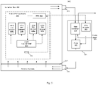
- FIG. 1 is a block diagram illustrating a data center system according to one embodiment.
- data center immersion cooling system 100 is referred to as a data center system with immersion cooling.
- data center immersion cooling system 100 includes data center or data center unit 101 coupled to external cooling unit 102.
- External cooling unit 102 may be an indirect evaporative cooling (IDEC) unit.
- Cooling unit 102 includes a heat exchanger 105, which may be a liquid-to-liquid heat exchanger or an air-to-liquid heat exchanger.
- heat exchanger 105 includes a primary loop 106 and a secondary loop 107.
- Primary loop 106 is utilized to circulate external cooling source such as external air or external liquid.
- Secondary loop 107 is utilized to circulate internal cooling liquid to exchange heat with the external cooling material of primary loop 106.
- data center 101 includes an immersion tank 103 filled with the internal cooling liquid, i.e., immersion cooling liquid. Although there is one immersion tank shown herein, more immersion tanks can also be included within data center 101.
- Immersion tank 103 contains one or more server systems 104 and each server blade includes one or more IT components (e.g., processors, memory, storage devices).
- Server systems 104 are submerged in the internal cooling liquid.
- the internal cooling liquid is thermally conductive dielectric liquid designed to extract the heat from the server systems. Such cooling technique is referred to as immersion cooling.
- Server immersion cooling is a computer cooling practice by which computer components or servers are submerged in a thermally conductive dielectric liquid.
- common dielectrics which are suitable for immersion cooling are typically oil-based.
- Server immersion cooling has the potential of becoming a popular server cooling solution for green data centers, as it allows them to drastically reduce their energy load, regardless of their PUE. Servers and other IT hardware cooled by immersion cooling do not require fans, thus these are removed.
- data center 101 includes a liquid supply line 111 and a liquid return line 112 coupled to the secondary side of the heat exchanger 105 of cooling system 102 to form the secondary loop.
- liquid supply line 111 is coupled to an intake port of immersion tank 103 and liquid return line 112 is coupled to an outlet port of immersion tank 103.
- Liquid supply line 111 is configured to receive the cooling liquid from heat exchanger 105 and to distribute the cooling liquid to immersion tank 103.
- Liquid return line 112 is configured to receive the cooling liquid carrying the heat exchanged from server blades 104 from immersion tank 103 and to return the cooling liquid back to heat exchanger 105 for heat exchange.
- a liquid pump 115 may be disposed on liquid return line 112 to pump and circulate the cooling liquid to flow within the secondary loop.
- multiple pumps may be designed in the system (on main supply line 111 or on main return line 112 for redundant purpose. Note that if there are multiple immersion tanks within data center 101, there will be multiple pairs of liquid supply line and liquid return line to couple the immersion tanks with heat exchanger 105 of cooling system 102. Unlike conventional cooling systems, the secondary loop 107 via liquid supply line 111, immersion tank 103, and liquid return line 112 is a single heat transfer loop without using a CDU in between.
- a CDU also includes a heat exchanger having a primary loop and a secondary loop therein, which will form multiple loops between cooling system 102 and immersion tank 103.
- liquid pump 115 may be disposed on liquid supply line 111 or alternatively, there may be multiple liquid pumps, one disposed on liquid supply line 111 and another one disposed on liquid return line 112.
- FIG 2 is a block diagram illustrating an example of a data center system 200 with thermoelectric cooling according to another embodiment.
- Figure 2 shows the system design view from the front side.
- the thermoelectric cooling system 200 may be utilized as a part of cooling system 100 of data center 101 as shown in Figure 1 .
- the entire system 200 may be submerged into the coolant within the immersion tank as shown in Figure 1 .
- the TEC element is disposed between computing chip and a heat sink.
- the TEC element including TEC element array 207 disposed between TIMs (205, 209), disposed between a heat sink, which includes heat sink fins disposed on the heat sink base 211, and a computing device, which is part of a package 203 disposed on a printed circuit board (PCB) 201.
- a TEC controller is disposed on the PCB, on the side of the package 203, connected with the TEC element array 207 via a wire 217.
- the TEC controller 215 is configured to control an electric current flowing within TEC element array 207.
- the flowing direction of the electric current within TEC element array 207 determines the operating mode of the TEC element array 207, either in a heating mode or a cooling mode.
- TEC element array 207 When operating in a heating mode, TEC element array 207 is configured to preheat package 203, and when operating in a cooling mode, TEC element array 207 is configured to provide cooling to package 203.
- Figure 3 is a block diagram illustrating an example of a data center system 300 with immersion cooling according to an embodiment.
- Figure 3 shows a GPU computing system configuration with immersion cooling and TEC device according to an embodiment.
- a GPU is utilized as an example of a data processing accelerator, however, other types of data processing logic may also be applicable.
- this design is a highly combined design with IT equipment. For example, it can be seen that some basic sections are the same as shown in Figure 2 .
- an immersion cooling tank 301 consists of dielectric fluid 305, IT equipment (GPU cards, GPU baseboard) 303, thermoelectric cooling (TEC) devices (309a, 309b, 309c, 309d) and TEC controllers 311 which are embedded in the IT equipment.
- a CDU 321 is outside the immersion tank 301, including a fluid pump 327, a heat exchanger 325 and a CDU controller 323.
- the heat exchanger 325 can perform its heat exchange function by using facility cooling liquid such as water 329.
- the CDU 321 is connected with immersion tank 301 through fluid port 315, 319.
- the dielectric fluid 305 flows through the perforated panel 317 from the fluid port 319 and exits immersion tank through the fluid port 315.
- the Board Management Controller (BMC) 307 can read GPU power / temperature / fluid inlet temperature (temperature sensor 313 is located near the perforated panel 317), can send control single to an on-board TEC controller 311 and CDU controller 323.
- the power consumption can be utilized as an index for a lookup operation in a predetermined control lookup table, which in turn determines the optimal TEC current to be applied to TEC elements 309a-309d (collectively referred to as TEC elements 309) and the optimal pump speed to control the pump speed of pump 327. Further detailed information concerning the control lookup table and the lookup operation will be described in details further below.
- the on-board TEC controller 311 provides electric current to each of the TEC devices (309a, 309b, 309c, 309d).
- the TEC controller 311 can regulate the current upon receiving the control signal from Board Management Controller (BMC) 307 according to an embodiment.
- BMC Board Management Controller
- the CDU controller 323 can send a control signal to the fluid pump 327 to change the pump speed.
- BMC 307 instructs TEC controller 311 to cause an electronic current to flow through the TEC devices in a particular direction (e.g., heating mode or cooling mode) based on an optimal TEC current obtained via the lookup operation in the control lookup table in view of the chip power consumption at the point in time.
- BMC 307 instructs the CDU controller 312 (or the pump controller) to set the pump speed of the fluid pump 327 based on the optimal pump speed obtained via the lookup operation.
- the cooling system e.g., TEC devices and CDU
- the above system specifications include: number of TEC element n serially connected in a TEC device, TEC element material constant 1, ⁇ (Seebeck coefficient, related to thermoelectric mechanism), TEC element material constant 2, K (thermal conductance), TEC element material constant 3, R (electrical resistance), reference value of thermal resistance of heat sink on top of the chip, R ⁇ th,hs .
- the above system specifications include that the operating condition is fluid inlet temperature T liquid,in ; the work load is chip generating power Q 0 ; the control parameters include Pump speed v pump , TEC current I; the system parameters are to determine (unknown): the TEC power overhead Q' (additional power needed when TEC is functioning); the chip case temperature T case , and the heat sink base temperature T hs,b .
- the cooling power consumption Q cooling for the entire system consists of TEC power overhead and the pump power, which are expressed as below:
- an optimal TEC current and an optimal pump speed can let the cooling power consumption of an immersion cooling system reach a minimum value, under a condition of a fluid temperature and a chip work load. That is, for a given fluid temperature and a given chip power consumption, an optimal TEC current and an optimal pump speed can be derived using the above formulas, in which the power consumption by the cooling system reaches minimum, while satisfying the thermal requirement (e.g., fluid temperature within a particular range by design).
- the optimization is stated as follows: finding an optimal system operational setting of (/, v pump ) so that the total cooling power consumption Q cooling is minimum, while T case ⁇ T case,max , I min ⁇ I ⁇ I max , v pump,min ⁇ v pump ⁇ v pump,max .
- the BMC monitors the chip power Q 0 , for a period of time such as 1 minute.
- the chip power for the purpose of determining the optimal TEC current and pump speed may be determined based on the averaged chip power measured over the period of time.
- the chip power of a particular point in time can be determined based on the electric current drawn by the chip and the voltage applied to the chip.
- BMC Based on the lookup operation, BMC sends a control signal (e.g., current, voltage) to TEC controller. In the meantime, BMC sends a control signal (e.g., current, voltage) to CDU controller, the CDU controller then sends a control signal the liquid pump. In response, TEC controller generates current and TEC device operates at I ⁇ and the fluid pump operates at the speed v pump ⁇ .
- a control signal e.g., current, voltage
- Figure 4 is a graph diagram of the TEC power over head versus the current of TEC device according to an embodiment.
- the system determines the optimal control parameters for a single value chip power Q 0 .
- Q ' vs. I has a trend as the curve in the Figure 4 .
- the Figure 4 shows TEC power overhead vs. TEC current.
- the tendency of Q ' can be analyzed to give a simple explanation.
- equation (3) is shown again as below:
- Q ′ n ⁇ I T hs , b ⁇ T case + I 2 R
- the first term is supposed to be large due to large ( T hs,b - T case ).
- the second term is supposed to be large. That is, the tendency of Q ' is at first decreasing and then increasing.
- the I 1 * can be obtained for the local minimum Q '.
- Q 0 I 1 ⁇ v pump , 1 ; I 2 ⁇ v pump , 2 ; I 3 ⁇ v pump , 3 ;
- the system can change the value of Q 0 and repeat operation 1.
- the size of this Table, N depends on the allowable memory space in the BMC.
- the Control Look-up Table includes a number of entries, each entry corresponding to a particular Q0. Each entry maps a particular Q0 to an optimal TEC current and an optimal pump speed. Note that each lookup table is trained and constructed for a particular predefined cooling system. Typically, a cooling system is designed to maintain the fluid temperature of the cooling fluid within a predetermined range. The TEC and CDU (e.g., pump) power consumption is proportional to the fluid temperature to be maintained.
- a control lookup table is associated with a particular range of the fluid temperatures, assuming the fluid temperature will not change significantly during the normal operations.
- the system may be configured as a universal system for a variety of liquid cooling requirements (e.g., different fluid temperatures).
- the system maintains a list of multiple control lookup tables, each corresponding to a different one of temperature ranges.
- the control lookup tables may be trained and configured under the similar cooling system environments. During the normal operations, dependent upon the specific fluid temperature (e.g., measured at an inlet), a proper one of the control lookup table is selected from the list of control lookup tables.
- the system can determine the chip power consumption Q0, for example, based on the current and voltage drawn by the chip. Based on the chip power value representing the power consumption, a lookup operation is performed to locate an entry matching the chip power value and to obtain the optimal TEC current and optimal pump speed from the matching entry.
- FIG. 5 is a block diagram illustrating an example of a data center system 400 with thermoelectric cooling for outdoor edge computing according to an embodiment.
- Figure 5 shows a GPU computing system configuration with immersion cooling and TEC device for outdoor edge computing according to an embodiment.
- this design is a highly combined design with IT equipment. For example, it can be seen that some basic sections are the same as shown in Figure 2 .
- an immersion cooling tank 401 includes dielectric fluid 405 (liquid and/or air), IT equipment (GPU cards, GPU baseboard) 403, thermoelectric cooling (TEC) devices (409a, 409b, 409c, 409d) and TEC controllers 411 which are embedded in the IT equipment.
- a CDU 421 is outside the immersion tank 401, including a fluid pump 427, a liquid-air heat exchanger 425 and a CDU controller 423.
- the liquid-air heat exchanger 425 can perform its heat exchange function by using liquid, air or a combination thereof.
- the CDU 421 is connected with immersion tank 401 through fluid port 415, 419.
- the dielectric fluid 405 flows through the perforated panel 417 from the fluid port 419 and exits immersion tank through the fluid port 415.
- the Board Management Controller (BMC) 407 can read GPU power / temperature / fluid inlet temperature (temperature sensor 413 is located near the perforated panel 417), can send control single to an on-board TEC controller 411 and CDU controller 423.
- the on-board TEC controller 411 provides current to each TEC device (409a, 409b, 409c, 409d).
- the TEC device (409a, 409b, 409c, 409d) is not functioning without current.
- the TEC controller 411 can regulate the current upon receiving the control signal from Board Management Controller (BMC) 407 according to an embodiment.
- BMC Board Management Controller
- the CDU controller 423 can send a control signal to the fluid pump 427 to change the pump speed.
- the immersion cooling system 400 is featured heating mode via TEC devices.
- the dielectric fluid 405 temperature may be so low that it causes computing chip is not able to start.
- TEC device (409a, 409b, 409c, 409d) can be controlled to work in a heating mode, yet with no additional heating source needed.
- the voltage and current in TEC can be reversed under the heating mode according to an embodiment.
- the TEC device (409a, 409b, 409c, 409d) can work as a heat pump which moves the energy from liquid (lower temperature) to the chip (higher temperature) so that the chip is preheated to a desired temperature.
- the TEC stops working in a heat mode.
- this immersion cooling system can perform self-protection via TEC devices when the pump fails. For example, upon pump failure the fluid is not driven by external force any more. In an embodiment, as chips keep generating heat, the fluid temperature keeps increasing. In an embodiment, fluid may become hot so fast that IT equipment is not able to finish backing up data or to transferring the workload before shutting down. In an embodiment, with higher TEC current, the TEC controller is able let TEC device cool the chip when fluid temperature is high, and this gives a larger time window for the system to finish necessary operations before shutting down.
- the procedures to obtain thermal resistance R ⁇ th,hs values during commissioning run can be obtained as follow.
- a thermocouple is placed between heatsink base and TEC to measure the temperature of heat sink base.
- a maximum pump speed v pump,max is set.
- the TEC current is shut down, so that TEC device is not functioning.
- the server is then turned on and a work load with the chip power Q ⁇ 0 (as long as the system without TEC device is able to dissipate this amount of power) is applied.
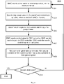
- Figure 6 is a flow diagram of an example process 500 for a cooling system according to an embodiment of the application.
- Figure 6 shows a control process for the immersion TEC cooling system to minimize cooling power consumption.
- the BMC monitors the real-time chip temperature with a monitor interval according to an embodiment.
- the BMC is configured to determine a first power value representing a power consumed by an electronic device based on a fluid temperature of cooling fluid that provides liquid cooling to the electronic device.
- an immersion tank is to contain the electronic device and the TEC device submerged into the cooling fluid contained therein.
- the CDU is located outside of the immersion tank.
- the cooling system can search the chip power value in the predefined control look-up table according to an embodiment.
- the predefined control look-up table is stored in BMC's memory.
- the BMC is configured to perform a lookup operation in a first control lookup table based on the first fluid temperature.
- the first control lookup table is corresponding to the first power value.
- the first control lookup table is one of a plurality of control lookup tables, each control lookup table corresponding to a particular power value.
- the cooling system selects the first control lookup table from the plurality of control lookup tables base on the first power value.
- the cooling system can determine the optimal TEC current and the optimal pump speed according to an embodiment.
- the BMC is configured to determine an optimal TEC current and an optimal pump speed based on the lookup operation.
- the optimal TEC current and the optimal pump speed are determined based on the lookup operation, such that power consumption of the cooling system reaches minimum while satisfying a thermal requirement of the electronic device.
- the BMC sends control to TEC controller according to an embodiment.
- the BMC sends a control signal to the CDU controller.
- the CDU controller sends a control signal to the fluid pump.
- the BMC is configured to determine the first power value based on the fluid temperature that is measured within a predetermined time period.
- the TEC controller generates a current and the TEC device operates at the optimal current according to an embodiment.
- fluid pump operates at the optimal speed.
- the TEC controller is to receive a first control signal from the BMC and to control a TEC device attached to the electronic device to cause the first TEC current to flow within the TEC device.
- the CDU controller is to receive a second control signal from BMC to configure a pump speed of a fluid pump of the CDU according to the first pump speed.
- the TEC controller is configured to cause the TEC current to flow in a second direction within the TEC device when the fluid temperature rises above a second predetermined temperature threshold, which causes the TEC device to operate in a cooling mode.
- the cooling system can decide whether the cooling system should shut down according to an embodiment. If not, then the system moves back the operation 501 according to an embodiment. If yes, then the process ends.
- Figure 7 is a flow diagram of an example process 600 for a cooling system according to an embodiment of the application.
- Figure 7 shows a control process for the immersion TEC cooling system to start in a cold weather.
- the BMC monitors the real-time chip temperature with a monitor interval according to an embodiment.
- the system sends control signal to TEC controller to reverse its voltage according to an embodiment.
- the TEC controller is configured to cause a TEC current to flow in a first direction within the TEC device when the fluid temperature drops below a first predetermined temperature threshold, which causes the TEC device to operate in a heating mode.
- the BMC sends control signal to fluid pump for lowest pump speed.
- the TEC controller generates reversed current of maximum value which the fluid pump operates at the lowest speed according to an embodiment.
- the BMC decides whether the chip temperature is above lower limit from BMC reading. If not, then the process moves the operation 609, which the BMC monitors the real-time chip temperature, with a monitor interval. If yes, then the process moves the operation 611, which BMC sends control signal to TEC controller; the TEC voltage is zero; the TEC exits the heating mode.
Landscapes
- Engineering & Computer Science (AREA)
- Physics & Mathematics (AREA)
- Microelectronics & Electronic Packaging (AREA)
- General Engineering & Computer Science (AREA)
- Thermal Sciences (AREA)
- Theoretical Computer Science (AREA)
- Computer Hardware Design (AREA)
- General Physics & Mathematics (AREA)
- Human Computer Interaction (AREA)
- Automation & Control Theory (AREA)
- Cooling Or The Like Of Electrical Apparatus (AREA)
Abstract
Description
- Embodiments of the present invention relate generally to data centers. More particularly, embodiments of the invention relate an efficient and robust system design and control method using thermoelectric cooling.
- Heat removal is a prominent factor in a computer system and data center design. The number of high performance electronics components such as high performance processors packaged inside servers have steadily increased, thereby increasing the amount of heat generated and dissipated during the ordinary operations of the servers. The reliability of servers used within a data center decreases if the environment in which they operate is permitted to increase in temperature over time. Maintaining a proper thermal environment is critical for normal operations of these servers in data centers, as well as the server performance and lifetime. It requires more effective and efficient heat removal solutions especially in the cases of cooling these high performance servers.
- Immersion cooling technology has brought many attentions recently. Many efforts are focusing on the fluid selection, information technology (IT) side design, material compatibilities, test and verification, and so on. Most of the solutions utilize existing cooling infrastructure (cooling water/chilled water) or system. In some of the solutions, a coolant distribution unit (CDU) is used to form an external cooling loop and an internal immersion cooling fluid loop. The external cooling loop can be adapted to any type of existing data center cooling infrastructures. These solutions may not fully utilize the advantages of immersion cooling.
- Thermoelectric cooling (TEC) technology also has also been spotlighted recently. Thermoelectric coolers have their own COP (coefficient of performance) optimization methods. The maximized COP is the lowest power overhead for a specific cooling power capacity of a TEC device. When a TEC device is embedded in an immersion-cooled IT equipment, the optimization of the entire cooling power consumption calculation including the TEC power over head and fluid pump power needs to be addressed.
- One of the promising applications of immersion cooling systems is its outdoor edge computing equipment. However, the weather has an impact on the system operation. For example, in a cold weather, the computing chip may be below its lowest temperature limit to function.
- When the fluid pump fails, the IT equipment performs certain operations before shutting down. These operations include backing up data in memory or transferring work load. At the same time, the dielectric fluid temperature continues increasing during these operations. A sufficiently large time window before shutting down IT equipment is essential to have a more robust immersion cooling system.
- Embodiments of the present disclosure seek to solve at least one of the problems existing in the related art to at least some extent.
- In embodiments of a first aspect of the present disclosure, a cooling system is provided, including: a board management controller (BMC) configured to determine a first power value representing a power consumed by an electronic device, perform a lookup operation in a control lookup table based on the first power value, and determine a first thermoelectric cooling (TEC) current and a first pump speed based on the lookup operation; a TEC controller to control a TEC device attached to the electronic device to cause the first TEC current to flow within the TEC device; and a cooling distribution unit (CDU) controller to configure a pump speed of a fluid pump of a CDU according to the first pump speed, wherein the CDU is to provide liquid cooling to the electronic device.
- In an embodiment, the control lookup table includes a plurality of entries, wherein each entry maps a particular power value to an optimal TEC current and an optimal pump speed corresponding to that particular power value.
- In an embodiment, the control lookup table is generated based on prior operational statistics data of a plurality of cooling systems, including determining optimal TEC currents and pump speeds for providing liquid cooling such that power consumption by each cooling system reaches minimum.
- In an embodiment, the cooling system further includes an immersion tank to contain the electronic device and the TEC device submerged into the cooling fluid contained therein.
- In an embodiment, the CDU is located outside of the immersion tank.
- In an embodiment, the BMC is configured to monitor operations of the electronic device for a predetermined period of time to obtain the first power value.
- In an embodiment, the first TEC current and the first pump speed are determined based on the lookup operation, such that power consumption of the cooling system reaches minimum while satisfying a thermal requirement of the electronic device.
- In an embodiment, the TEC controller is configured to cause a TEC current to flow in a first direction within the TEC device when a fluid temperature of a fluid of the liquid cooling drops below a first predetermined temperature threshold, which causes the TEC device to operate in a heating mode.
- In an embodiment, the TEC controller is configured to cause the TEC current to flow in a second direction within the TEC device when the fluid temperature rises above a second predetermined temperature threshold, which causes the TEC device to operate in a cooling mode.
- In an embodiment, the cooling system has the following governing equations:

- In an embodiment, the cooling system has a cooling power consumption consisting of the TEC power overhead and a pump power.
- In embodiments of a second aspect of the present disclosure, an electronic rack of a data center is provided, including: one or more electronic devices operating as one or more servers; and the cooling system as defined in any of the above embodiments, coupled to the one or more electronic devices.
- In embodiments of a third aspect of the present disclosure, a method for providing liquid cooling is provided, including: determining a first power value representing a power consumed by an electronic device; performing a lookup operation in a control lookup table based on the first power value; determining a first thermoelectric cooling (TEC) current and a first pump speed based on the lookup operation; causing the first TEC current to flow within the TEC device; and configuring a pump speed of a fluid pump of a CDU according to the first pump speed, wherein the CDU is to provide liquid cooling to the electronic device.
- In an embodiment, the control lookup table includes a plurality of entries, wherein each entry maps a particular power value to an optimal TEC current and an optimal pump speed corresponding to that particular power value.
- In an embodiment, the control lookup table is generated based on prior operational statistics data of a plurality of cooling systems, including determining optimal TEC currents and pump speeds for providing liquid cooling such that power consumption by each cooling system reaches minimum.
- Embodiments of the invention are illustrated by way of example and not limitation in the figures of the accompanying drawings in which like references indicate similar elements.
-
Figure 1 is a block diagram illustrating an example of a data center system with thermoelectric cooling according to one embodiment. -
Figure 2 is a block diagram illustrating an example of a portion of data center system with thermoelectric cooling according to another embodiment. -
Figure 3 is a block diagram illustrating an example of a data center system with thermoelectric cooling according to an embodiment. -
Figure 4 is a graph diagram of the TEC power over head versus the current of TEC device according to an embodiment. -
Figure 5 is a block diagram illustrating another example of a data center system with thermoelectric cooling according to another embodiment. -
Figure 6 is a flow diagram of an example process for a thermoelectric cooling system according to an embodiment of the application. -
Figure 7 is another flow diagram of an example process for a thermoelectric cooling system under a heating mode according to another embodiment of the application. - Various embodiments and aspects of the inventions will be described with reference to details discussed below, and the accompanying drawings will illustrate the various embodiments. The following description and drawings are illustrative of the invention and are not to be construed as limiting the invention. Numerous specific details are described to provide a thorough understanding of various embodiments of the present invention. However, in certain instances, well-known or conventional details are not described in order to provide a concise discussion of embodiments of the present inventions.
- Reference in the specification to "one embodiment" or "an embodiment" means that a particular feature, structure, or characteristic described in conjunction with the embodiment can be included in at least one embodiment of the invention. The appearances of the phrase "in one embodiment" in various places in the specification do not necessarily all refer to the same embodiment.
- The IT Hardware industry is a critical market for many reasons: it plays a crucial role in business competitiveness, service quality and availability, and also plays a significant role in the infrastructure TCO. IT Hardware is closely linked with the profit of an organization. It is one of the core competencies of the internet giant, cloud computing service providers, as well as high performance computing and AI computing related business service users and providers who build, operate, compute, store and manage other IT hardware platforms and infrastructures. The majority of the hyper-scale owners are customizing full-stacks of these hardware systems. For instance, in the rapidly growing cloud computing business, the performance and cost (both capital cost and operation cost) of computing and storage hardware systems, clusters and infrastructure, all require the service providers to create customized systems that fit their individual needs the best. These markets require continuous innovation. An efficient system design and operation benefits the service providers in multiple aspects in a long term. The key to this is to develop continuously with more resilience, efficiency, and cost effective solutions and architecture.
- In this disclosure, an immersion cooling system is discussed. In an embodiment, an immersion cooling tank consists of dielectric fluid, IT equipment (graphics/general processing unit or GPU cards, GPU baseboard), thermoelectric cooling (TEC) devices and TEC controllers which are embedded in the IT equipment. In an embodiment, a CDU is outside the immersion tank, including a fluid pump, a heat exchanger and a CDU controller. In an embodiment, the cooling system can make a real-time optimization of the pump speed and TEC current, to minimize the system's cooling power consumption, based on monitoring the computing chip's power in real-time.
- In an embodiment, the system can be featured under the heating mode via TEC devices. For example, when this immersion system is used as edge computing equipment, the dielectric fluid temperature may be so low that the computing chip is not able to start. In this condition, TEC devices can be controlled to work in a heating mode, with no additional heating source needed, according to an embodiment. In an embodiment, the TEC device works as a heat pump to move the energy from the liquid (lower temperature) to the chip (higher temperature) so that the chip is preheated to a desired temperature.
- In an embodiment, this system can perform self-protection via TEC devices when the pump fails. In an embodiment, upon pump failure, the fluid is not driven by external forces any more. For example, as the chip keeps generating heat, the fluid's temperature keeps increasing. Therefore, in an embodiment, the fluid may become very hot in a short amount of time. Then, IT equipment is not able to finish backing up data or transfer the workload, and shuts down instead. In an embodiment, with the higher current, the controller is able to let the TEC device cool the chip with higher fluid temperature, and this gives a larger time window for the system to finish necessary operations before shutting down.
- In an embodiment, a data center system comprises a plurality of electronic racks, each electronic rack including one or more servers; and a cooling system coupled to the electronic racks to provide liquid cooling to the servers. In an embodiment, a cooling system comprises a board management controller (BMC), a thermoelectric cooling (TEC) controller, and a cooling distribution unit (CDU) controller.
- In an embodiment, a BMC is configured to monitor the cooling system to obtain a first power value representing a power consumed by an electronic device. In an embodiment, a BMC is configured to perform a lookup operation in a control lookup table based on the first power value. In an embodiment, a BMC is configured to determine a first thermoelectric cooling (TEC) current and a first pump speed based on the lookup operation.
- In an embodiment, a TEC controller is configured to receive a first control signal from the BMC to control a TEC device attached to the electronic device to cause the first TEC current to flow within the TEC device. In an embodiment, a CDU controller is configured to receive a second control signal from BMC to configure a pump speed of a fluid pump of the CDU according to the first pump speed.
- In an embodiment, the control lookup table includes a number of entries, each entry mapping a particular power value to an optimal TEC current and an optimal pump speed corresponding to that particular power value. In an embodiment, a cooling system further includes an immersion tank to contain the electronic device and the TEC device submerged into the cooling fluid contained therein. In an embodiment, the CDU is located outside of the immersion tank.
- In an embodiment, the BMC is configured to monitor the cooling system for a predetermined period of time to obtain a first power value. In an embodiment, the first TEC current and the first pump speed are determined based on the lookup operation, such that power consumption of the cooling system reaches minimum while satisfying a thermal requirement of the electronic device.
- In an embodiment, the TEC controller is configured to cause a TEC current to flow in a first direction within the TEC device when the fluid temperature of the cooling fluid drops below a first predetermined temperature threshold, which causes the TEC device to operate in a heating mode. In an embodiment, the TEC controller is configured to cause the TEC current to flow in a second direction within the TEC device when the fluid temperature rises above a second predetermined temperature threshold, which causes the TEC device to operate in a cooling mode.
-
Figure 1 is a block diagram illustrating a data center system according to one embodiment. Referring toFigure 1 , data centerimmersion cooling system 100 is referred to as a data center system with immersion cooling. In one embodiment, data centerimmersion cooling system 100 includes data center ordata center unit 101 coupled toexternal cooling unit 102.External cooling unit 102 may be an indirect evaporative cooling (IDEC) unit.Cooling unit 102 includes aheat exchanger 105, which may be a liquid-to-liquid heat exchanger or an air-to-liquid heat exchanger. Typically,heat exchanger 105 includes aprimary loop 106 and asecondary loop 107.Primary loop 106 is utilized to circulate external cooling source such as external air or external liquid.Secondary loop 107 is utilized to circulate internal cooling liquid to exchange heat with the external cooling material ofprimary loop 106. - In one embodiment,
data center 101 includes animmersion tank 103 filled with the internal cooling liquid, i.e., immersion cooling liquid. Although there is one immersion tank shown herein, more immersion tanks can also be included withindata center 101.Immersion tank 103 contains one ormore server systems 104 and each server blade includes one or more IT components (e.g., processors, memory, storage devices).Server systems 104 are submerged in the internal cooling liquid. The internal cooling liquid is thermally conductive dielectric liquid designed to extract the heat from the server systems. Such cooling technique is referred to as immersion cooling. - Server immersion cooling is a computer cooling practice by which computer components or servers are submerged in a thermally conductive dielectric liquid. For example, common dielectrics which are suitable for immersion cooling are typically oil-based. Server immersion cooling has the potential of becoming a popular server cooling solution for green data centers, as it allows them to drastically reduce their energy load, regardless of their PUE. Servers and other IT hardware cooled by immersion cooling do not require fans, thus these are removed.
- Referring back to
Figure 1 , according to one embodiment,data center 101 includes aliquid supply line 111 and aliquid return line 112 coupled to the secondary side of theheat exchanger 105 ofcooling system 102 to form the secondary loop. In addition,liquid supply line 111 is coupled to an intake port ofimmersion tank 103 andliquid return line 112 is coupled to an outlet port ofimmersion tank 103.Liquid supply line 111 is configured to receive the cooling liquid fromheat exchanger 105 and to distribute the cooling liquid toimmersion tank 103.Liquid return line 112 is configured to receive the cooling liquid carrying the heat exchanged fromserver blades 104 fromimmersion tank 103 and to return the cooling liquid back toheat exchanger 105 for heat exchange. - In addition, a
liquid pump 115 may be disposed onliquid return line 112 to pump and circulate the cooling liquid to flow within the secondary loop. In addition, multiple pumps may be designed in the system (onmain supply line 111 or onmain return line 112 for redundant purpose. Note that if there are multiple immersion tanks withindata center 101, there will be multiple pairs of liquid supply line and liquid return line to couple the immersion tanks withheat exchanger 105 ofcooling system 102. Unlike conventional cooling systems, thesecondary loop 107 vialiquid supply line 111,immersion tank 103, andliquid return line 112 is a single heat transfer loop without using a CDU in between. Typically, a CDU also includes a heat exchanger having a primary loop and a secondary loop therein, which will form multiple loops betweencooling system 102 andimmersion tank 103. Also note thatliquid pump 115 may be disposed onliquid supply line 111 or alternatively, there may be multiple liquid pumps, one disposed onliquid supply line 111 and another one disposed onliquid return line 112. -
Figure 2 is a block diagram illustrating an example of adata center system 200 with thermoelectric cooling according to another embodiment. For example,Figure 2 shows the system design view from the front side. Thethermoelectric cooling system 200 may be utilized as a part ofcooling system 100 ofdata center 101 as shown inFigure 1 . For example, theentire system 200 may be submerged into the coolant within the immersion tank as shown inFigure 1 . In an embodiment, the TEC element is disposed between computing chip and a heat sink. For example, the TEC element, includingTEC element array 207 disposed between TIMs (205, 209), disposed between a heat sink, which includes heat sink fins disposed on theheat sink base 211, and a computing device, which is part of apackage 203 disposed on a printed circuit board (PCB) 201. In an embodiment, a TEC controller is disposed on the PCB, on the side of thepackage 203, connected with theTEC element array 207 via awire 217. TheTEC controller 215 is configured to control an electric current flowing withinTEC element array 207. The flowing direction of the electric current withinTEC element array 207 determines the operating mode of theTEC element array 207, either in a heating mode or a cooling mode. When operating in a heating mode,TEC element array 207 is configured to preheatpackage 203, and when operating in a cooling mode,TEC element array 207 is configured to provide cooling to package 203. -
Figure 3 is a block diagram illustrating an example of adata center system 300 with immersion cooling according to an embodiment.Figure 3 shows a GPU computing system configuration with immersion cooling and TEC device according to an embodiment. Note that a GPU is utilized as an example of a data processing accelerator, however, other types of data processing logic may also be applicable. In an embodiment, this design is a highly combined design with IT equipment. For example, it can be seen that some basic sections are the same as shown inFigure 2 . - In an embodiment, an
immersion cooling tank 301 consists ofdielectric fluid 305, IT equipment (GPU cards, GPU baseboard) 303, thermoelectric cooling (TEC) devices (309a, 309b, 309c, 309d) andTEC controllers 311 which are embedded in the IT equipment. In an embodiment, aCDU 321 is outside theimmersion tank 301, including afluid pump 327, aheat exchanger 325 and aCDU controller 323. In an embodiment, theheat exchanger 325 can perform its heat exchange function by using facility cooling liquid such aswater 329. In an embodiment, theCDU 321 is connected withimmersion tank 301 throughfluid port dielectric fluid 305 flows through theperforated panel 317 from thefluid port 319 and exits immersion tank through thefluid port 315. - In an embodiment, the Board Management Controller (BMC) 307 can read GPU power / temperature / fluid inlet temperature (
temperature sensor 313 is located near the perforated panel 317), can send control single to an on-board TEC controller 311 andCDU controller 323. In one embodiment,BMC 307 can determine the power consumption of a processor, for example, by determining an electric current drawn by the processor and a voltage applied to the processor using proper current and voltage sensors. That is the power consumption of the processor can be calculated as power = current ∗ voltage. The power consumption can be utilized as an index for a lookup operation in a predetermined control lookup table, which in turn determines the optimal TEC current to be applied toTEC elements 309a-309d (collectively referred to as TEC elements 309) and the optimal pump speed to control the pump speed ofpump 327. Further detailed information concerning the control lookup table and the lookup operation will be described in details further below. - In an embodiment, the on-
board TEC controller 311 provides electric current to each of the TEC devices (309a, 309b, 309c, 309d). TheTEC controller 311 can regulate the current upon receiving the control signal from Board Management Controller (BMC) 307 according to an embodiment. In an embodiment, theCDU controller 323 can send a control signal to thefluid pump 327 to change the pump speed.BMC 307 instructsTEC controller 311 to cause an electronic current to flow through the TEC devices in a particular direction (e.g., heating mode or cooling mode) based on an optimal TEC current obtained via the lookup operation in the control lookup table in view of the chip power consumption at the point in time. Similarly,BMC 307 instructs the CDU controller 312 (or the pump controller) to set the pump speed of thefluid pump 327 based on the optimal pump speed obtained via the lookup operation. As a result, the cooling system (e.g., TEC devices and CDU) consumes the minimum (or optimal power) while provide sufficient cooling (and/or heating) to the electronic devices. - In an embodiment, the governing equations of the system are shown below:

- For example, the above system specifications include: number of TEC element n serially connected in a TEC device, TEC element material constant 1, α (Seebeck coefficient, related to thermoelectric mechanism), TEC element material constant 2, K (thermal conductance), TEC element material constant 3, R (electrical resistance), reference value of thermal resistance of heat sink on top of the chip, R̂th,hs. Further, the above system specifications include that the operating condition is fluid inlet temperature Tliquid,in; the work load is chip generating power Q 0; the control parameters include Pump speed vpump , TEC current I; the system parameters are to determine (unknown): the TEC power overhead Q' (additional power needed when TEC is functioning); the chip case temperature Tcase , and the heat sink base temperature Ths,b.
- Since there are 3 unknown parameters in 3 governing equations, with a given fluid inlet temperature Tliquid,in, the TEC power overhead Q' and chip case temperature Tcase can be calculated. These definite relations can be denoted as f 1 and f2.; Q' = (Q 0 ,I, vpump ); and Tcase = f2 (Q 0 ,I, vpump ). Please be noted that we consider Ths,b > Tcase as a practical working condition when TEC is in cooling mode. Note that for a particular configured emersion cooling system, the fluid inlet temperature is maintained within a predetermined range as a part of the design configuration. Such fluid inlet temperature normally would not and should not change significantly over the course of operations. The goal is for the cooling system to consume minimum power while maintain the fluid temperature of the cooling fluid within the predetermined range by finding the optimal TEC current and optimal pump speed of the liquid pump.
- In an embodiment, the cooling power consumption Qcooling for the entire system consists of TEC power overhead and the pump power, which are expressed as below:

- In an embodiment, the description of optimization can be expressed as: an optimal TEC current and an optimal pump speed can let the cooling power consumption of an immersion cooling system reach a minimum value, under a condition of a fluid temperature and a chip work load. That is, for a given fluid temperature and a given chip power consumption, an optimal TEC current and an optimal pump speed can be derived using the above formulas, in which the power consumption by the cooling system reaches minimum, while satisfying the thermal requirement (e.g., fluid temperature within a particular range by design). In an embodiment, mathematically, the optimization is stated as follows: finding an optimal system operational setting of (/, vpump ) so that the total cooling power consumption Qcooling is minimum, while Tcase < Tcase,max, Imin ≤ I ≤ Imax, vpump,min ≤ vpump ≤ vpump,max.
- Initially, the BMC monitors the chip power Q 0, for a period of time such as 1 minute. The chip power for the purpose of determining the optimal TEC current and pump speed may be determined based on the averaged chip power measured over the period of time. The chip power of a particular point in time can be determined based on the electric current drawn by the chip and the voltage applied to the chip.
- The BMC can search Q 0 value in the predefined Control Look-up Table in BMC's memory, determine the optimal TEC current I ∗ and the optimal pump speed


- Based on the lookup operation, BMC sends a control signal (e.g., current, voltage) to TEC controller. In the meantime, BMC sends a control signal (e.g., current, voltage) to CDU controller, the CDU controller then sends a control signal the liquid pump. In response, TEC controller generates current and TEC device operates at I ∗ and the fluid pump operates at the speed

-
Figure 4 is a graph diagram of the TEC power over head versus the current of TEC device according to an embodiment. For example, at operation 1, the system determines the optimal control parameters for a single value chip power Q 0. InFigure 4 , Q' vs. I has a trend as the curve in theFigure 4 . In an embodiment, theFigure 4 shows TEC power overhead vs. TEC current. In an embodiment, the tendency of Q' can be analyzed to give a simple explanation. For example, equation (3) is shown again as below:
- In an embodiment, when I is near Imin (Imin > 0), the first term is supposed to be large due to large (Ths,b - Tcase ). In an embodiment, when I is near Imax , the second term is supposed to be large. That is, the tendency of Q' is at first decreasing and then increasing.
- In an embodiment, for one pump speed v pump,1, the

In an embodiment, under chip power's real-time,
- In an embodiment, substituting (


- At operation 2, the system can change the value of Q 0 and repeat operation 1.
- At operation 3, the system can generate a Control Look-up Table in a format as below:




- In an embodiment, the size of this Table, N, depends on the allowable memory space in the BMC. In one embodiment, if the operating condition Tliauid,in (inlet fluid temperature) changes, the Control Look-up Table should be redefined. In one embodiment, the lookup table includes a number of entries, each entry corresponding to a particular Q0. Each entry maps a particular Q0 to an optimal TEC current and an optimal pump speed. Note that each lookup table is trained and constructed for a particular predefined cooling system. Typically, a cooling system is designed to maintain the fluid temperature of the cooling fluid within a predetermined range. The TEC and CDU (e.g., pump) power consumption is proportional to the fluid temperature to be maintained. Thus, a control lookup table is associated with a particular range of the fluid temperatures, assuming the fluid temperature will not change significantly during the normal operations.
- In one embodiment, the system may be configured as a universal system for a variety of liquid cooling requirements (e.g., different fluid temperatures). As a result, the system maintains a list of multiple control lookup tables, each corresponding to a different one of temperature ranges. The control lookup tables may be trained and configured under the similar cooling system environments. During the normal operations, dependent upon the specific fluid temperature (e.g., measured at an inlet), a proper one of the control lookup table is selected from the list of control lookup tables.
- During the operations, the system can determine the chip power consumption Q0, for example, based on the current and voltage drawn by the chip. Based on the chip power value representing the power consumption, a lookup operation is performed to locate an entry matching the chip power value and to obtain the optimal TEC current and optimal pump speed from the matching entry.
-
Figure 5 is a block diagram illustrating an example of adata center system 400 with thermoelectric cooling for outdoor edge computing according to an embodiment.Figure 5 shows a GPU computing system configuration with immersion cooling and TEC device for outdoor edge computing according to an embodiment. In an embodiment, this design is a highly combined design with IT equipment. For example, it can be seen that some basic sections are the same as shown inFigure 2 . - In an embodiment, an
immersion cooling tank 401 includes dielectric fluid 405 (liquid and/or air), IT equipment (GPU cards, GPU baseboard) 403, thermoelectric cooling (TEC) devices (409a, 409b, 409c, 409d) andTEC controllers 411 which are embedded in the IT equipment. In an embodiment, aCDU 421 is outside theimmersion tank 401, including afluid pump 427, a liquid-air heat exchanger 425 and aCDU controller 423. In an embodiment, the liquid-air heat exchanger 425 can perform its heat exchange function by using liquid, air or a combination thereof. In an embodiment, theCDU 421 is connected withimmersion tank 401 throughfluid port dielectric fluid 405 flows through theperforated panel 417 from thefluid port 419 and exits immersion tank through thefluid port 415. - In an embodiment, the Board Management Controller (BMC) 407 can read GPU power / temperature / fluid inlet temperature (
temperature sensor 413 is located near the perforated panel 417), can send control single to an on-board TEC controller 411 andCDU controller 423. - In an embodiment, the on-
board TEC controller 411 provides current to each TEC device (409a, 409b, 409c, 409d). For example, the TEC device (409a, 409b, 409c, 409d) is not functioning without current. TheTEC controller 411 can regulate the current upon receiving the control signal from Board Management Controller (BMC) 407 according to an embodiment. In an embodiment, theCDU controller 423 can send a control signal to thefluid pump 427 to change the pump speed. - In an embodiment, the
immersion cooling system 400 is featured heating mode via TEC devices. For example, when thisimmersion system 400 is used as edge computing equipment, thedielectric fluid 405 temperature may be so low that it causes computing chip is not able to start. In an embodiment, under this condition, TEC device (409a, 409b, 409c, 409d) can be controlled to work in a heating mode, yet with no additional heating source needed. - Further, the voltage and current in TEC (409a, 409b, 409c, 409d) can be reversed under the heating mode according to an embodiment. For example, the TEC device (409a, 409b, 409c, 409d) can work as a heat pump which moves the energy from liquid (lower temperature) to the chip (higher temperature) so that the chip is preheated to a desired temperature. In an embodiment, after the chip is able to start, the TEC stops working in a heat mode.
- In an embodiment, this immersion cooling system can perform self-protection via TEC devices when the pump fails. For example, upon pump failure the fluid is not driven by external force any more. In an embodiment, as chips keep generating heat, the fluid temperature keeps increasing. In an embodiment, fluid may become hot so fast that IT equipment is not able to finish backing up data or to transferring the workload before shutting down. In an embodiment, with higher TEC current, the TEC controller is able let TEC device cool the chip when fluid temperature is high, and this gives a larger time window for the system to finish necessary operations before shutting down.
- In an embodiment, the procedures to obtain thermal resistance R̂th,hs values during commissioning run can be obtained as follow. First, a thermocouple is placed between heatsink base and TEC to measure the temperature of heat sink base. Then a maximum pump speed vpump,max is set. The TEC current is shut down, so that TEC device is not functioning. The server is then turned on and a work load with the chip power Q̂ 0 (as long as the system without TEC device is able to dissipate this amount of power) is applied. For example, when the system reaches a steady state, the system reads the temperature of heat sink base T̂hs,b to obtain:

-
Figure 6 is a flow diagram of anexample process 500 for a cooling system according to an embodiment of the application. For example,Figure 6 shows a control process for the immersion TEC cooling system to minimize cooling power consumption. - At
operation 501, the BMC monitors the real-time chip temperature with a monitor interval according to an embodiment. In an embodiment, the BMC is configured to determine a first power value representing a power consumed by an electronic device based on a fluid temperature of cooling fluid that provides liquid cooling to the electronic device. In an embodiment, an immersion tank is to contain the electronic device and the TEC device submerged into the cooling fluid contained therein. In an embodiment, the CDU is located outside of the immersion tank. - At
operation 503, the cooling system can search the chip power value in the predefined control look-up table according to an embodiment. For example, the predefined control look-up table is stored in BMC's memory. In an embodiment, the BMC is configured to perform a lookup operation in a first control lookup table based on the first fluid temperature. In an embodiment, the first control lookup table is corresponding to the first power value. In an embodiment, the first control lookup table is one of a plurality of control lookup tables, each control lookup table corresponding to a particular power value. In an embodiment, the cooling system selects the first control lookup table from the plurality of control lookup tables base on the first power value. - At
operation 505, the cooling system can determine the optimal TEC current and the optimal pump speed according to an embodiment. For example, the BMC is configured to determine an optimal TEC current and an optimal pump speed based on the lookup operation. In an embodiment, the optimal TEC current and the optimal pump speed are determined based on the lookup operation, such that power consumption of the cooling system reaches minimum while satisfying a thermal requirement of the electronic device. - At
operation 507, the BMC sends control to TEC controller according to an embodiment. In an embodiment, the BMC sends a control signal to the CDU controller. In an embodiment, the CDU controller sends a control signal to the fluid pump. In an embodiment, the BMC is configured to determine the first power value based on the fluid temperature that is measured within a predetermined time period. - At
operation 509, the TEC controller generates a current and the TEC device operates at the optimal current according to an embodiment. In an embodiment, fluid pump operates at the optimal speed. For example, the TEC controller is to receive a first control signal from the BMC and to control a TEC device attached to the electronic device to cause the first TEC current to flow within the TEC device. In an embodiment, the CDU controller is to receive a second control signal from BMC to configure a pump speed of a fluid pump of the CDU according to the first pump speed. In an embodiment, the TEC controller is configured to cause the TEC current to flow in a second direction within the TEC device when the fluid temperature rises above a second predetermined temperature threshold, which causes the TEC device to operate in a cooling mode. - At
operation 511, the cooling system can decide whether the cooling system should shut down according to an embodiment. If not, then the system moves back theoperation 501 according to an embodiment. If yes, then the process ends. -
Figure 7 is a flow diagram of anexample process 600 for a cooling system according to an embodiment of the application. For example,Figure 7 shows a control process for the immersion TEC cooling system to start in a cold weather. - At
operation 601, the BMC monitors the real-time chip temperature with a monitor interval according to an embodiment. Atoperation 603, the system sends control signal to TEC controller to reverse its voltage according to an embodiment. For example, the TEC controller is configured to cause a TEC current to flow in a first direction within the TEC device when the fluid temperature drops below a first predetermined temperature threshold, which causes the TEC device to operate in a heating mode. In an embodiment, the BMC sends control signal to fluid pump for lowest pump speed. - At
operation 605, the TEC controller generates reversed current of maximum value which the fluid pump operates at the lowest speed according to an embodiment. Atoperation 607, the BMC decides whether the chip temperature is above lower limit from BMC reading. If not, then the process moves theoperation 609, which the BMC monitors the real-time chip temperature, with a monitor interval. If yes, then the process moves theoperation 611, which BMC sends control signal to TEC controller; the TEC voltage is zero; the TEC exits the heating mode. - In the foregoing specification, embodiments of the invention have been described with reference to specific exemplary embodiments thereof. It will be evident that various modifications may be made thereto without departing from the broader spirit and scope of the invention as set forth in the following claims. The specification and drawings are, accordingly, to be regarded in an illustrative sense rather than a restrictive sense.
Claims (15)
- A cooling system, comprising:a board management controller (BMC) (307, 407) configured todetermine a first power value representing a power consumed by an electronic device,perform a lookup operation in a control lookup table based on the first power value, anddetermine a first thermoelectric cooling (TEC) current and a first pump speed based on the lookup operation;a TEC controller (311, 411) to control a TEC device (309a, 309b, 309c, 309d, 401a, 401b, 401c, 401d) attached to the electronic device to cause the first TEC current to flow within the TEC device (309a, 309b, 309c, 309d, 401a, 401b, 401c, 401d); anda cooling distribution unit (CDU) controller (323, 423) to configure a pump speed of a fluid pump (327, 427) of a CDU (321, 421) according to the first pump speed, wherein the CDU (321, 421) is to provide liquid cooling to the electronic device.
- The cooling system of claim 1, wherein the control lookup table comprises a plurality of entries, wherein each entry maps a particular power value to an optimal TEC current and an optimal pump speed corresponding to that particular power value.
- The cooling system of claim 1 or 2, wherein the control lookup table is generated based on prior operational statistics data of a plurality of cooling systems, including determining optimal TEC currents and pump speeds for providing liquid cooling such that power consumption by each cooling system reaches minimum.
- The cooling system of any one of claims 1-3, further comprising an immersion tank (103, 301, 401) to contain the electronic device and the TEC device (309a, 309b, 309c, 309d, 401a, 401b, 401c, 401d) submerged into the cooling fluid contained therein.
- The cooling system of claim 4, wherein the CDU (321, 421) is located outside of the immersion tank (103, 301, 401).
- The cooling system of any one of claims 1-5, wherein the BMC (307, 407) is configured to monitor operations of the electronic device for a predetermined period of time to obtain the first power value.
- The cooling system of any one of claims 1-6, wherein the first TEC current and the first pump speed are determined based on the lookup operation, such that power consumption of the cooling system reaches minimum while satisfying a thermal requirement of the electronic device.
- The cooling system of any one of claims 1-7, wherein the TEC controller (311, 411) is configured to cause a TEC current to flow in a first direction within the TEC device (309a, 309b, 309c, 309d, 401a, 401b, 401c, 401d) when a fluid temperature of a fluid of the liquid cooling drops below a first predetermined temperature threshold, which causes the TEC device (309a, 309b, 309c, 309d, 401a, 401b, 401c, 401d) to operate in a heating mode.
- The cooling system of claim 8, wherein the TEC controller (311, 411) is configured to cause the TEC current to flow in a second direction within the TEC device (309a, 309b, 309c, 309d, 401a, 401b, 401c, 401d) when the fluid temperature rises above a second predetermined temperature threshold, which causes the TEC device (309a, 309b, 309c, 309d, 401a, 401b, 401c, 401d) to operate in a cooling mode.
- The cooling system of any one of claims 1-9, wherein the cooling system has the following governing equations:

- The cooling system of claim 10, wherein the cooling system has a cooling power consumption consisting of the TEC power overhead and a pump power.
- An electronic rack of a data center (101), comprising:one or more electronic devices operating as one or more servers (104); andthe cooling system of any one of claims 1-11, coupled to the one or more electronic devices.
- A method for providing liquid cooling, comprising:determining a first power value representing a power consumed by an electronic device;performing a lookup operation in a control lookup table based on the first power value;determining a first thermoelectric cooling (TEC) current and a first pump speed based on the lookup operation;causing the first TEC current to flow within the TEC device (309a, 309b, 309c, 309d, 401a, 401b, 401c, 401d); andconfiguring a pump speed of a fluid pump (327, 427) of a CDU (321, 421) according to the first pump speed, wherein the CDU (321, 421) is to provide liquid cooling to the electronic device.
- The method of claim 13, wherein the control lookup table comprises a plurality of entries, wherein each entry maps a particular power value to an optimal TEC current and an optimal pump speed corresponding to that particular power value.
- The method of claim 13, wherein the control lookup table is generated based on prior operational statistics data of a plurality of cooling systems, including determining optimal TEC currents and pump speeds for providing liquid cooling such that power consumption by each cooling system reaches minimum.
Applications Claiming Priority (1)
| Application Number | Priority Date | Filing Date | Title |
|---|---|---|---|
| US17/212,075 US11683916B2 (en) | 2021-03-25 | 2021-03-25 | Efficient and robust system design and control method using thermoelectric cooling |
Publications (2)
| Publication Number | Publication Date |
|---|---|
| EP4025026A2 true EP4025026A2 (en) | 2022-07-06 |
| EP4025026A3 EP4025026A3 (en) | 2022-09-28 |
Family
ID=80933302
Family Applications (1)
| Application Number | Title | Priority Date | Filing Date |
|---|---|---|---|
| EP22164019.6A Withdrawn EP4025026A3 (en) | 2021-03-25 | 2022-03-24 | Efficient and robust system design and control method using thermoelectric cooling |
Country Status (4)
| Country | Link |
|---|---|
| US (1) | US11683916B2 (en) |
| EP (1) | EP4025026A3 (en) |
| JP (1) | JP2022084812A (en) |
| CN (1) | CN115135098B (en) |
Cited By (1)
| Publication number | Priority date | Publication date | Assignee | Title |
|---|---|---|---|---|
| WO2024098112A1 (en) * | 2022-11-10 | 2024-05-16 | Firmus Metal Technologies Singapore Pte Ltd | Tank for cooling of computing devices using liquid immersion |
Families Citing this family (4)
| Publication number | Priority date | Publication date | Assignee | Title |
|---|---|---|---|---|
| TWI807318B (en) * | 2021-05-07 | 2023-07-01 | 緯穎科技服務股份有限公司 | Electronic apparatus having immersion cooling system and operating method thereof |
| JP7267494B1 (en) * | 2022-09-29 | 2023-05-01 | Kddi株式会社 | Server system |
| CN116068453B (en) * | 2023-03-20 | 2023-07-18 | 广州锐速智能科技股份有限公司 | IGBT high-power power supply module detection method and system for DC ecology |
| WO2025151448A1 (en) * | 2024-01-08 | 2025-07-17 | MTS IP Holdings Ltd | Systems for immersion cooling tank controller communication |
Family Cites Families (15)
| Publication number | Priority date | Publication date | Assignee | Title |
|---|---|---|---|---|
| JPS5145228B2 (en) * | 1972-12-01 | 1976-12-02 | ||
| JP2006215882A (en) * | 2005-02-04 | 2006-08-17 | Hitachi Ltd | Disk array device and liquid cooling device thereof |
| RU2533864C2 (en) * | 2012-11-15 | 2014-11-20 | Ивано-Франковский национальный технический университет нефти и газа | System of thermoelectric polarisation of drum-shoe brake friction pad surfaces in test conditions |
| US10331189B2 (en) * | 2015-02-12 | 2019-06-25 | Dell Products L.P. | Fan speed determination for improved power management in information handling systems |
| US10345875B2 (en) * | 2016-02-18 | 2019-07-09 | Lenovo Enterprise Solutions (Singapore) Pte. Ltd. | Hybrid passive and active cooling assembly |
| US20200214173A1 (en) * | 2017-07-18 | 2020-07-02 | Nec Corporation | Phase-change cooling apparatus and phase-change cooling method |
| TWI640387B (en) * | 2017-08-31 | 2018-11-11 | 台灣積體電路製造股份有限公司 | Cooling system for optimization control and automatic control method thereof |
| US10238011B1 (en) | 2017-10-10 | 2019-03-19 | Baidu Usa Llc | Optimal controller for hybrid liquid-air cooling system of electronic racks of a data center |
| KR20200002601A (en) * | 2018-06-29 | 2020-01-08 | 한국과학기술원 | Method and apparatus for thermoelectric cooling |
| US10667427B2 (en) * | 2018-07-05 | 2020-05-26 | Baidu Usa Llc | Immersion cooling system for data centers |
| US10925180B2 (en) * | 2019-03-04 | 2021-02-16 | Baidu Usa Llc | IT container system design approach for fast deployment and high compatibility application scenarios |
| US10939580B2 (en) | 2019-03-25 | 2021-03-02 | Baidu Usa Llc | Control strategy for immersion cooling system |
| US11212946B2 (en) | 2019-09-18 | 2021-12-28 | Baidu Usa Llc | Performance-per-watt optimal control logic in liquid cooling solution for high performance machine-learning computing |
| US11429085B2 (en) * | 2020-05-28 | 2022-08-30 | Dell Products L.P. | Systems and methods for thermal control of an information handling resource using thermoelectric effect |
| CN112416098A (en) * | 2020-11-13 | 2021-02-26 | 上海英众信息科技有限公司 | Computer heat abstractor and control system thereof |
-
2021
- 2021-03-25 US US17/212,075 patent/US11683916B2/en active Active
-
2022
- 2022-03-23 JP JP2022046310A patent/JP2022084812A/en active Pending
- 2022-03-24 EP EP22164019.6A patent/EP4025026A3/en not_active Withdrawn
- 2022-03-25 CN CN202210307604.5A patent/CN115135098B/en active Active
Cited By (1)
| Publication number | Priority date | Publication date | Assignee | Title |
|---|---|---|---|---|
| WO2024098112A1 (en) * | 2022-11-10 | 2024-05-16 | Firmus Metal Technologies Singapore Pte Ltd | Tank for cooling of computing devices using liquid immersion |
Also Published As
| Publication number | Publication date |
|---|---|
| CN115135098B (en) | 2025-08-26 |
| EP4025026A3 (en) | 2022-09-28 |
| US20220312644A1 (en) | 2022-09-29 |
| CN115135098A (en) | 2022-09-30 |
| US11683916B2 (en) | 2023-06-20 |
| JP2022084812A (en) | 2022-06-07 |
Similar Documents
| Publication | Publication Date | Title |
|---|---|---|
| US11683916B2 (en) | Efficient and robust system design and control method using thermoelectric cooling | |
| US12150282B2 (en) | Liquid submerged, horizontal computer server rack and systems and method of cooling such a server rack | |
| US10238009B2 (en) | Coolant and ambient temperature control for chillerless liquid cooled data centers | |
| CN109656336B (en) | Optimized controller for hybrid liquid-air cooling system of electronics rack of data center | |
| US20180213685A1 (en) | Provisioning cooling elements for chillerless data centers | |
| US7310737B2 (en) | Cooling system for computer systems | |
| US9445529B2 (en) | Liquid cooled data center design selection | |
| CN111654995B (en) | IT container system design scheme for fast deployment and high compatibility application scenarios | |
| Patel | A vision of energy aware computing from chips to data centers | |
| US8074456B2 (en) | Thermal management system having thermoelectric modules | |
| US8457806B2 (en) | Managing an infrastructure having a 3D package and cooling resource actuators | |
| US11510346B2 (en) | Method and system for enhancing electronics cooling using a thermoelectric element | |
| US11552345B2 (en) | Power architecture design for thermal management of battery backup energy storage | |
| Sahini et al. | Comparative study of high ambient inlet temperature effects on the performance of air vs. liquid cooled IT equipment | |
| US20220061187A1 (en) | Hybrid cooling system for electronic racks | |
| Shahi et al. | Experimental Study Demonstrating Pumping Power Savings at Rack Level Using Dynamic Cooling | |
| US11259447B2 (en) | Composite liquid cooling device | |
| Schmidt et al. | Moderating the Impact of Integrating Water-Cooled Servers Into Data Centers | |
| US20250318080A1 (en) | Direct liquid contact electronics cooling system with multimode functionality |
Legal Events
| Date | Code | Title | Description |
|---|---|---|---|
| PUAI | Public reference made under article 153(3) epc to a published international application that has entered the european phase |
Free format text: ORIGINAL CODE: 0009012 |
|
| STAA | Information on the status of an ep patent application or granted ep patent |
Free format text: STATUS: THE APPLICATION HAS BEEN PUBLISHED |
|
| AK | Designated contracting states |
Kind code of ref document: A2 Designated state(s): AL AT BE BG CH CY CZ DE DK EE ES FI FR GB GR HR HU IE IS IT LI LT LU LV MC MK MT NL NO PL PT RO RS SE SI SK SM TR |
|
| REG | Reference to a national code |
Ref country code: DE Ref legal event code: R079 Free format text: PREVIOUS MAIN CLASS: H05K0007200000 Ipc: G06F0001200000 |
|
| PUAL | Search report despatched |
Free format text: ORIGINAL CODE: 0009013 |
|
| AK | Designated contracting states |
Kind code of ref document: A3 Designated state(s): AL AT BE BG CH CY CZ DE DK EE ES FI FR GB GR HR HU IE IS IT LI LT LU LV MC MK MT NL NO PL PT RO RS SE SI SK SM TR |
|
| RIC1 | Information provided on ipc code assigned before grant |
Ipc: G06F 1/3203 20190101ALI20220819BHEP Ipc: G06F 1/28 20060101ALI20220819BHEP Ipc: H05K 7/20 20060101ALI20220819BHEP Ipc: G06F 1/20 20060101AFI20220819BHEP |
|
| STAA | Information on the status of an ep patent application or granted ep patent |
Free format text: STATUS: THE APPLICATION IS DEEMED TO BE WITHDRAWN |
|
| 18D | Application deemed to be withdrawn |
Effective date: 20230329 |