EP4025025A1 - Cooling device and method of manufacturing the same - Google Patents
Cooling device and method of manufacturing the same Download PDFInfo
- Publication number
- EP4025025A1 EP4025025A1 EP21205717.8A EP21205717A EP4025025A1 EP 4025025 A1 EP4025025 A1 EP 4025025A1 EP 21205717 A EP21205717 A EP 21205717A EP 4025025 A1 EP4025025 A1 EP 4025025A1
- Authority
- EP
- European Patent Office
- Prior art keywords
- cooling
- cooling plate
- mating
- electronic components
- power electronic
- Prior art date
- Legal status (The legal status is an assumption and is not a legal conclusion. Google has not performed a legal analysis and makes no representation as to the accuracy of the status listed.)
- Pending
Links
Images


Classifications
-
- H—ELECTRICITY
- H05—ELECTRIC TECHNIQUES NOT OTHERWISE PROVIDED FOR
- H05K—PRINTED CIRCUITS; CASINGS OR CONSTRUCTIONAL DETAILS OF ELECTRIC APPARATUS; MANUFACTURE OF ASSEMBLAGES OF ELECTRICAL COMPONENTS
- H05K7/00—Constructional details common to different types of electric apparatus
- H05K7/20—Modifications to facilitate cooling, ventilating, or heating
- H05K7/20845—Modifications to facilitate cooling, ventilating, or heating for automotive electronic casings
- H05K7/20872—Liquid coolant without phase change
-
- H—ELECTRICITY
- H05—ELECTRIC TECHNIQUES NOT OTHERWISE PROVIDED FOR
- H05K—PRINTED CIRCUITS; CASINGS OR CONSTRUCTIONAL DETAILS OF ELECTRIC APPARATUS; MANUFACTURE OF ASSEMBLAGES OF ELECTRICAL COMPONENTS
- H05K7/00—Constructional details common to different types of electric apparatus
- H05K7/20—Modifications to facilitate cooling, ventilating, or heating
- H05K7/20218—Modifications to facilitate cooling, ventilating, or heating using a liquid coolant without phase change in electronic enclosures
- H05K7/20254—Cold plates transferring heat from heat source to coolant
-
- H—ELECTRICITY
- H05—ELECTRIC TECHNIQUES NOT OTHERWISE PROVIDED FOR
- H05K—PRINTED CIRCUITS; CASINGS OR CONSTRUCTIONAL DETAILS OF ELECTRIC APPARATUS; MANUFACTURE OF ASSEMBLAGES OF ELECTRICAL COMPONENTS
- H05K1/00—Printed circuits
- H05K1/02—Details
- H05K1/0201—Thermal arrangements, e.g. for cooling, heating or preventing overheating
-
- H—ELECTRICITY
- H05—ELECTRIC TECHNIQUES NOT OTHERWISE PROVIDED FOR
- H05K—PRINTED CIRCUITS; CASINGS OR CONSTRUCTIONAL DETAILS OF ELECTRIC APPARATUS; MANUFACTURE OF ASSEMBLAGES OF ELECTRICAL COMPONENTS
- H05K1/00—Printed circuits
- H05K1/02—Details
- H05K1/0201—Thermal arrangements, e.g. for cooling, heating or preventing overheating
- H05K1/0203—Cooling of mounted components
-
- H—ELECTRICITY
- H05—ELECTRIC TECHNIQUES NOT OTHERWISE PROVIDED FOR
- H05K—PRINTED CIRCUITS; CASINGS OR CONSTRUCTIONAL DETAILS OF ELECTRIC APPARATUS; MANUFACTURE OF ASSEMBLAGES OF ELECTRICAL COMPONENTS
- H05K1/00—Printed circuits
- H05K1/02—Details
- H05K1/0201—Thermal arrangements, e.g. for cooling, heating or preventing overheating
- H05K1/0203—Cooling of mounted components
- H05K1/0204—Cooling of mounted components using means for thermal conduction connection in the thickness direction of the substrate
Definitions
- the present disclosure relates to a cooling device for cooling a plurality of electronic components mounted on a circuit board, and a method of manufacturing the same.
- the present disclosure is particularly relevant to cold plates for cooling electronic control units for automotive applications and most particularly to multi domain controllers (MDCs).
- MDCs multi domain controllers
- liquid cooling systems are often used due to their high cooling efficiency.
- a cold plate which is a device typically having a flat metal body with an internal circuit of cooling channels or tubes through which coolant fluid may be circulated. In use, the cold plate is fitted against the electronic components and, as components get hot, heat is transferred through the body and cooling tubes into the coolant, from where it is transported away from the circuit.
- PCB printed circuit board
- SoCs System-on-a-Chip
- other components may be low-power components which require cooling, but generate less waste heat and hence have lower heat transfer demands.
- passive components such as diodes and capacitors, which do not require active cooling at all.
- the passive components are typically geometrically higher (i.e. taller) than adjacent high-power and low-power components.
- pedestals are typically formed of the same metal as the body of the cold plate, such as aluminium, and provide a column of thermally conductive material for establishing a thermal path from the high or low power component through to the cold plate.
- the length of the thermal path means that pedestals nevertheless present a significant thermal resistance.
- the pedestals therefore provide a sub-optimal thermal connection between the component and the coolant.
- TIM Thermal Interface Material
- the contact force between pedestals and components is hard to control in conventional arrangements. As such, this further contributes to the thermal resistance during heat exchange.
- the present disclosure concerns a cooling device and method for manufacturing a cooling device for cooling a plurality of electronic components mounted on a circuit board.
- the cooling device may be a cold plate for use with an electronic control unit or multi domain controller.
- a cooling device for cooling a plurality of high-power electronic components mounted on a circuit board, the device including: a plurality of cooling plate assemblies, each including a cooling plate for mating to one of the high-power electronic components and an enclosure mounted to the cooling plate for defining a coolant transport path over at least part of a surface thereof; and one or more conduits connecting between the cooling plate assemblies for fluid communication between their respective coolant transport paths, wherein the conduits are flexible such that the relative positions of the cooling plates are adjustable for mating to respective high-power electronic components in different planes; and wherein the cooling plates are formed of sheet metal and each cooling plate includes a mating face for mating flat against a top surface of its respective high-power electronic component.
- cooling may be targeted to the primary heat sources on a circuit board. That is, by allowing the relative positions of each cooling plate to be independently adjusted for its respective high-power component, the surface area of the top of each high-power component in mating contact with the opposing surface of the cooling plate may be maximised. This thereby ensures optimised heat transfer away from the component surfaces into the cooling plate.
- the enclosures provide a coolant fluid pathway which is located very close to the high-power components, with the relatively thin, substantially planar configuration of the sheet metal cooling plate providing a short thermal path between these components and the coolant fluid being circulated therein. Accordingly, a high cooling efficiency may be achieved, with a simple and light construction.
- the cooling plates are formed of pressed sheet metal. This provides for a low weight, cost effective construction.
- the cooling plates are formed from dye cast sheets.
- the mating face includes component formations for mating to the top surfaces of one or more other electronic components.
- the mating face may be three dimensionally shaped for mating against components of different heights.
- relatively taller or shorter components can be accommodated and cooled by the same cooling plate.
- the mating face may be shaped to have projected regions for mating with shorter components and recessed regions for mating with taller components.
- this is achieved with a simple and light sheet metal construction.
- the component formations are formed by pressing.
- the component formations are formed by dye cast formations.
- each cooling plate is configured to overlay one or more other electronic components mounted on the circuit board.
- the planar position of each cooling plate may be optimised for a respective high-power component, whilst the cooling plate may nevertheless also sit above and transfer heat away from other components.
- the cooling plate may be configured to also overlay one or more other low-power components for actively cooling these components.
- Such low-power components may have lower cooling demand than adjacent high-power components and therefore are more tolerant of a less optimised thermal contact. Consequently, a greater distance between low-power components and the cooling plate may be provided for in the shaping of the cooling plate where this is required to optimise contact with the high-power components.
- Thermal interface material may be provided for filling the gaps between the other components and the cooling plate in such instances. Although this represents a higher thermal resistance, this is still acceptable for low-power components.
- At least one of the plurality of cooling plate assemblies includes a second cooling plate and wherein the enclosure is mounted to both the cooling plate and the second cooling plate.
- the enclosure may be provided as a fluid conduit bridging across two adjacent cooling plates.
- a cooling plate and a neighboring cooling plate may be connected by a common enclosure. This removes the need for separate enclosures and a flexible conduit to connect them, and hence a lower number of components and less material is required to achieve effective cooling.
- the enclosure is provided as a flexible profile, such as an aluminum flexible profile.
- the enclosure mounted to both the cooling plate and the second cooling plate is formed as a flattened fluid conduit for longitudinal flexibility such that the relative positions of the cooling plate and second cooling plate are adjustable for mating to respective high-power electronic components in different planes.
- the shape of the enclosure structure such as a thin rectangular prism shape, in combination with the thinness of the enclosure material, allows the enclosure to flex along its length. Consequently, differences in height may be accommodated by cooling plates mounted to different ends of the enclosure.
- the enclosures are formed of sheet metal, such as folded planar sheets or extruded thin walled structures.
- the enclosures may be formed by extruded flexible profiles, such as flexible extruded aluminum profiles. These thereby provide an inexpensive and thermally efficient structure.
- the enclosures are fixed to the cooling plates by at least one of brazing, soldering, welding, or gluing. Other joining process are also possible.
- one or more conduits have a maximum bend radius of less than 45mm. In this way, a flexible construction is provided which maintains fluid flow without kinking.
- the one or more conduits include one of an elastomer tube or a flexible (e.g. corrugated) metal tube such as a metallic bellow. In this way, the relative positions of the cooling plates may be easily adjusted.
- the cooling device further includes a plurality of couplings for biassing the cooling plates toward the circuit board for mating to the high-power electronic components.
- a localised compressive pressure may be applied to the cooling plate at a number of different locations over its footprint.
- the couplings may be distributed to provide a consistent compressive pressure around each high-power component. This may also maintain the mating between the cooling plates and the high-power components throughout different operating conditions, thereby providing improved cooling consistency. At the same time, the volume of thermal interface material required to maintain an effective thermal contact is minimised.
- the couplings include a fixture for connection to the circuit board and a spring coupled to the fixture for applying a biassing force to the respective cooling plate.
- the springs may allow a consistent compressive pressure to be applied and maintained. Furthermore, by securing the cooling plate directly to the circuit board, a compact assembly may be provided.
- the cooling device further comprises a biasing means for biassing the circuit board toward the cooling plate. In this way, mating between the cooling plate and the components on the circuit board may be facilitated without necessitating further attachment holes in the circuit board.
- the cooling plates have a footprint shaped for exposing one or more other electronic components mounted to the circuit board when the respective cooling plate is mated to its high-power electronic component. In this way, the cooling plates may sit below taller passive components and thereby reduce the distance of the thermal path from shorter, high-power components.
- each cooling plate assembly includes a shaped sheet fixed to an upper face of the cooling plate to define a fluid cavity for forming the coolant transport path therebetween.
- each enclosure may be formed, for example, by pressing or bending sheet metal to define the cavities which make up the coolant transport circuit.
- the enclosure may then be brazed, welded, soldered, or glued to the contact sheet to provide a fluid tight mounting for the coolant transport circuit.
- the shaped metal sheet defines one or more substantially cuboidal or rectangular prism shaped fluid transport cavities.
- the shaped sheet is formed of an elastomer.
- the elastomeric structures may be produced by any one of compression moulding, injection moulding or pressure thermoforming.
- the elastomer shaped sheet is formed integrally with the one or more conduits.
- a continuous body may be provided to define both the enclosures and the connecting conduits. This may mitigate the risks of coolant leakage between sections and simplify manufacture and assembly.
- the cooling device further comprises elastic elements for securing the cooling device to the circuit board. In this way, good thermal contact between the cooling plates and the high-power electronic components may be maintained.
- the enclosures have a flattened configuration. In this way, the coolant is able to spread over a large area of the upper face of each cooling plate, thereby improving the efficiency at which heat is drawn from it.
- the coolant transport path of each cooling plate assembly is defined by the space between the enclosure and the cooling plate. In this way, coolant may flow directly over an upper surface of the cooling plate, thereby minimising the length of the thermal path between the coolant and the high-power components.
- the cooling plates are formed of sheet metal, a flat piece of metal may be simply bent or pressed into the required shape. At the same time, the metal may provide a high level of thermal conduction, and the thin construction minimises the volume and weight of material required.
- the cooling plates are 2mm-3mm thick. This may provide for the effective transport of the heat from the hot components.
- the cooling plates are formed by dye casting into the required shape. This construction is still quite flat, minimising the mass of material.
- the enclosure may contain additional metal structures (e.g. fins) providing an increased cooling surface in contact to the coolant.
- additional metal structures e.g. fins
- a method of manufacturing a cooling device for cooling a plurality of high-power electronic components mounted on a circuit board including the steps of: shaping a plurality of cooling plates to each mate to one of the plurality of high-power electronic components; mounting enclosures to each of the cooling plates for forming cooling plate assemblies, wherein a coolant transport path is defined between each enclosure and at least part of a surface of its respective cooling plate; and connecting one or more conduits between the cooling plate assemblies for fluid communication between their respective coolant transport paths, wherein the conduits are flexible such that the relative positions of the cooling plates are adjustable for mating to respective high-power electronic components in different planes, and wherein the cooling plates are formed of sheet metal to comprise a mating face for mating flat against a top surface of its respective high-power electronic component.
- the step of shaping the plurality of cooling plates further includes pressing component formations into the mating face for mating to the top surfaces of one or more other electronic components. In other embodiments, the step of shaping the plurality of cooling plates further includes dye casting component formations into the mating face for mating to the top surfaces of one or more other electronic components.
- a cooling device for cooling a plurality of high-power electronic components mounted on a circuit board, the device including: first and second cooling plates each comprising a mating face for mating flat against a top surface of one of the high-power electronic components; and a flattened fluid conduit mounted to the first and second cooling plates for defining a coolant transport path; wherein the flattened fluid conduit is formed of sheet metal having a thickness for allowing longitudinal flexibility of the flattened fluid conduit such that the relative positions of the first and second cooling plates are adjustable for mating to respective high-power electronic components in different planes.
- the first and second cooling plates are formed of sheet metal.
- the flattened fluid conduit is formed as an extruded sheet metal structure, such as a flexible profile.
- a cooling device for cooling a plurality of high-power electronic components mounted on a circuit board, including: providing a plurality of cooling plate assemblies connected by one or more flexible conduits, wherein each cooling plate assembly includes a cooling plate and an enclosure mounted to the cooling plate for defining a coolant transport path over at least part of a surface thereof, wherein the conduits provide fluid communication between the coolant transport paths; and mating each cooling plate to one of the plurality of high-power electronic components, wherein the relative positions of the cooling plates are adjusted for mating to their respective high-power electronic components in different planes; and wherein the cooling plates are formed of sheet metal and each cooling plate includes a mating face for mating flat against a top surface of its respective high-power electronic component.
- each cooling plate is configured to mate with one or more other electronic components mounted on the circuit board, and wherein the use of the cooling device further includes applying a first layer of TIM having a first thickness to each of the plurality of high-power electronic components, and applying a second layer of TIM having a second thickness to one or more of the other electronic components.
- the second thickness is greater than the first thickness.
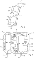
- FIG. 1 shows a first embodiment of a cooling device 100 mounted to a circuit board 1.
- the cooling device 100 includes a plurality of cooling plate assemblies 3, which are each associated with a high-power component provided on the circuit board.
- four cooling plate assemblies 3a-d are provided corresponding to the four high-power components provided on this circuit board 1, as is described in further detail below.
- Each cooling plate assembly 3 includes a cooling plate 31 and an enclosure 32 mounted thereto.
- the cooling plate 31 is formed of a sheet metal material, such as aluminium, and is shaped so that its footprint keys between the taller passive components 10 provided on the circuit board 1. As such, each cooling plate 31 may be seated closer to the circuit board 1, beneath the tops of the passive components 10 and overlaying the high-power and low-power components on the circuit board.
- the shaping of the cooling plates 31 may be achieved by various methods, for example by stamping, deep drawing, hydro forming, electron-beam cutting, and 3D-printing.
- the cooling plates 31 further includes coupling apertures 33 through which the cooling plate assembly may be secured to the circuit board 1, as is described in further detail below.
- the enclosures 32 are formed of a shaped metal sheet and define a hollow cavity over a portion of the upper surface of each respective cooling plate 31. As such, the hollow cavities defined by each enclosure 32 forms a fluid transport path for coolant over the cooling plate 31.
- the cooling plate assemblies 3 are connected by three conduits 4. Two shorter conduits 4 are provided between the first and second cooling plate assemblies 3a,3b and the third and fourth cooling plate assemblies 3c,3d. A longer conduit 4 is provided between the second and third cooling plate assemblies 3a, 3b.
- the conduits 4 are connected into the enclosures 32 of each cooling plate assembly 3 through a port and thereby establish fluid communication between the enclosures 32. As such, the enclosures 32 and the conduits 4 form a coolant transport circuit through which coolant can be circulated. In use, coolant is fed into the circuit though inlet 2, which feeds the enclosure of the first cooling plate assembly 3a, and coolant is fed out from the enclosure of the fourth cooling plate assembly 3d through the outlet 5.
- the conduits 4 are formed of a flexible corrugated metal tube, having a bellow type construction. As such, the conduits 4 may bend whilst remaining securely connected to the ports of the respective enclosures 32 to which they are connected. Fluid communication between the enclosures 31 may thereby be maintained whilst allowing the cooling plate assemblies 3a-d to be moved and angled relative to one another, albeit that they are restrained by the length of each conduit 4.
- the conduit 4 has a minimum bend radius of 25mm, with this being the minimum inside radius at which the tube may be bent without kinking it.
- the required flexibility of the conduit 4 will vary depending on the size of the circuit and the required relative heights of the cooling plate assemblies 3a-d. That said, once the cooling plate assemblies 3a-d are fitted to the circuit board 1, the conduits 4 should be sufficiently flexible that they do not apply tension to the cooling plates 31 which could cause the plates 31 to pull or twist away from their engagement with the electronic components beneath.
- figure 2 shows a cross sectional view through one of the cooling plate assemblies 3 shown in Figure 1 .
- the cooling plate 31 is seated on top of a high-power component 7 and two lower-power components 8 mounted on the circuit board 1.
- the bottom surface of the cooling plate 31 provides a mating face 311 which sits flat on the top face of the high-power component 7.
- the mating face 311 is positioned in effectively the same plane as the top face of the high-power component 7, with the two surfaces substantially abutting one another. That said, a thin layer of thermal interface material (TIM) may be provided between the surfaces to compensate for surface roughness.
- TIM thermal interface material
- this TIM layer 9 may be provided as a thermal grease which wets the surface asperities on the opposing faces of the high-power component 7 and the mating face 311 to provide optimal thermal coupling, whilst keeping the TIM layer as thin as possible to enhance heat transfer.
- the mating face 311 further includes component recess 312 to accommodate low-power components 8 which are taller than the adjacent high-power component 7.
- the top face of the low-power component 8 on the right of the high-power component 7 is taller and hence is located within the component recess 312. This thereby allows the mating face 311 to abut the top of the high-power component 7.
- a thicker layer of TIM 9 may be provided between the top face of the right-hand low-power component 8 and the opposing surface within the component recess 312 to compensate for any differences in alignment between these surfaces.
- the plane of the mating face 311 is aligned with the top face of the high-power component 7 to optimise the thermal connection with this component.
- this engagement plane may be different from the plane of the top face of the right-hand low-power component 8, and consequently, any angular differences may be compensated by the TIM 9.
- the coupling apertures 33 provided in the cooling plate 31 receive biassing fixtures 6, which are used to connect the cooling plate assemblies 3 to the circuit board 1.
- Each biassing fixture 6 includes a screw 62 and a compression spring 61 arranged coaxially with the screw 61.
- the compression spring 61 is compressed between the screw head 63 and the upper surface of the cooling plate 31.
- the biasing fixtures apply an equal biassing force to the cooling plate 31 to force its mating face 311 into uniform contact with the high-power component 7.
- This application of a consistent compressive force allows mechanical stresses arising due to external vibrations, as well as different rates of thermal expansion between different components, to be accommodated. As such, a good thermal contact is maintained between the cooling plate 31 and the underlying high-power component 7 throughout different operating conditions.
- contact can be maintained despite variations in the operating loads and the thermal expansion coefficients of different components.
- contact can be maintained even when vibrations arise during driving. This may thereby compensate for any dimensional variations in the assembly which could otherwise result in larger air gaps between the contacting surfaces.
- the need for Thermal Interface Material (TIM) is limited to compensating for any residual gaps that could arise due to the surface roughness of the high-power component 7 and cooling plate 31. Therefore, only a very thin layer of TIM is required.
- biassing members may be provided instead of or in addition to the screw and spring arrangement shown in Figure 2 .
- a biassing force may be applied by springs or elastomeric pressure pieces mounted below, to the side or above the cooling plate 31.
- biassing members may be attached to a housing which is used to enclose the circuit board 1 and cooling device 100.
- a guiding structure may be provided to restrain lateral movement of each cooling plate assembly 3 relative to the circuit board 1, whilst the biassing force is applied through the housing to maintain thermal contact.
- the cooling device 100 may be mounted to the circuit board 1 using precisely machined spacers, without applying a biassing force. However, low tolerance manufacturing would be required with such an arrangement in order to keep opposing surfaces as close as possible.
- the enclosure 32 is mounted to the upper surface of cooling plate 31 and forms the interior cavity 34 which provides the fluid path for the coolant.
- the enclosure 32 is formed of a three-dimensionally shaped metal sheet, which is connected directly to the upper surface of the cooling plate 31 by, for example, brazing, soldering, or welding.
- the coolant fluid path is thereby provided by the space between the two sheet metals.
- the sheet may be shaped, for example, by stamping, deep drawing, hydro forming and electron-beam cutting.
- the enclosure 32 is defined by a number of substantially cuboid sections to simplify the shaping process. Other enclosure arrangements may also be used, as is described in further detail below.
- FIG 3 shows a top view of an illustrative circuit board 1 onto which the cooling device 100 shown in Figure 1 may be attached.
- the circuit board 1 is a printed circuit board including a plurality of components. It this example, the circuit board 1 includes four System-on-Chip components 7a-d which are critical high-power components that generate considerable waste heat during use. Surrounding these are a plurality of low-power components 8, which require cooling but generate less heat. There are also a large number of passive components 10 which do not require active cooling.
- FIG 4 shows the circuit 1 of Figure 1 once the cooling device 100 has been fitted.
- the four cooling plate assemblies 3a-d are aligned with individual ones of the high-power components 7a-d. Consequently, as described in relation to Figure 2 , each cooling plate assembly 3a-d is optimised for cooling its respective high-power component 7a-d.
- the cooling plate assemblies 3a-d also cool the adjacent low-power components 8, whilst their footprints sit in the spaces between the taller passive components 10 (also see Figure 1 ).
- the footprint may include metal strips 34 extending from the main body of the cooling plate 31 for covering these remote low-power components.
- these strips could be three dimensionally shaped in order to bridge over obstacles, such as other components, which may otherwise be in the way.
- the taller passive components 10 may be left exposed. As discussed above, this thereby allows the cooling plates 31 to seat closer to the circuit board 1, against the tops of the shorted high-power components 7.
- coolant for example a water/glycol mixture
- inlet pipe 2 enters and fills the first enclosure 32.
- the coolant flows through the conduits and other enclosures and out through the outlet 5.
- coolant is flooded over the surface area occupied by the enclosure 32, drawing heat from its upper surface.
- the inlet and outlet pipes 2,5 may be fed by the vehicle's cooling system.
- each cooling plate assembly 3a-d provides optimised thermal contact with its respective high-power component 7. As such, the coolant is located much closer to those components than they would in a conventional cold plate arrangement. At the same time, each cooling plate 31 contains less material compared to conventional cold plates. A very high cooling efficiency may therefore be achieved, at the same time as reducing weight.
- FIGs 5a and 5b respectively show top and isometric views of a cooling device according to a second embodiment when fitted to the circuit board 1 shown in Figure 3 .
- This embodiment is similar to the embodiment described above, except that the enclosures 32 are provided as thin planar containers which, owing to their flexibility, may be mounted across more than one cooling plate 31.
- the embodiment shown in Figures 5a and 5b has two cooling plate assemblies 3e,3f, which each comprise two cooling plates 31a,31b.
- Each cooling plate 31a,31b is aligned with a respective high-power electronic component 7a-d located on the circuit board 1.
- the enclosures 32 are each formed from thin, flexible metallic sheet which has been shaped into a rectangular prism to form a fluid conduit with a flattened profile. As such, the contacting faces of the enclosures 32 mounted to the cooling plates 31a,31b present a large surface area for heat transfer.
- the thinness of the metallic sheet and the planar configuration of the enclosure structure also means that the enclosures 32 are sufficiently flexible that, when mounted to the adjacent cooling plates 31a,31b, height differences between those neighbouring cooling plates 31 can be tolerated. As such, height differences between components associated with those cooling plates can be compensated for, whilst avoiding the need for separate enclosures and conduits between neighbouring cooling plates. This therefore reduces the number of parts and the complexity of the arrangement because the use of conduits 4 can be limited to instances where larger gaps or height differences need to be bridged.
- the enclosures 32 in this embodiment further include coolant collector regions 35 located at their ends. These sections form expanded structures for connecting the inlet and outlet 2,5, as well as the conduit 4 bridging between the sections.
- the coolant collector regions 35 also form enlarged cavities within the internal fluid channel of the enclosures 31 for collecting coolant and feeding it through the fluid circuit.
- screws fixed to spacers may be used to bias the cooling plates 31 into mating contact with the components on the circuit board 1.
- FIGS 6 and 7 show a cooling device according to a third embodiment.
- This embodiment is similar to the first embodiment, except that the enclosures 32 and the conduits 4 are formed of an elastomer.
- the enclosures 32 and conduits 4 are formed integrally, and the enclosure parts 32 are then mounted to their respective cooling plates 31 using an adhesive.
- the enclosure 32 might be connected to their respective cooling plates 31 using an injection moulding process.
- Fluid connectors 21,51 for connection to an external coolant circuit are integrated into the inlet 2 and outlet 5 sections of the elastomer material by injection moulding around them.
- the elastomer conduits 4 provide the flexibility needed to optimise mating between the high-power components 7 and the cooling plates 31.
- the elastomer enclosure 32 provides a lightweight assembly, which is also securely sealed owing to its integral construction.
- the elastomer enclosures 32 and conduits 4 may alternatively be formed of two or more parts which are joined together. In this case, although joints are required, the common elastomer allows secure sealing between the parts.
- each cooling plate assembly may be associated with more than one high-power component, albeit that the thermal efficiency for those high-power components may be compromised by such an arrangement.
Landscapes
- Engineering & Computer Science (AREA)
- Microelectronics & Electronic Packaging (AREA)
- Physics & Mathematics (AREA)
- Thermal Sciences (AREA)
- Cooling Or The Like Of Electrical Apparatus (AREA)
- Cooling Or The Like Of Semiconductors Or Solid State Devices (AREA)
Abstract
Description
- The present disclosure relates to a cooling device for cooling a plurality of electronic components mounted on a circuit board, and a method of manufacturing the same. The present disclosure is particularly relevant to cold plates for cooling electronic control units for automotive applications and most particularly to multi domain controllers (MDCs).
- Some electronic components get hot during use, which can subsequently compromise their function or lead to component damage. As such, it is common to fit cooling devices to electronic circuitry to maintain their operating temperature within an acceptable tolerance. For particularly high demand applications, liquid cooling systems are often used due to their high cooling efficiency. Conventional liquid cooling systems often have a cold plate, which is a device typically having a flat metal body with an internal circuit of cooling channels or tubes through which coolant fluid may be circulated. In use, the cold plate is fitted against the electronic components and, as components get hot, heat is transferred through the body and cooling tubes into the coolant, from where it is transported away from the circuit.
- Although some electronic components on a printed circuit board (PCB) can become very hot in use, other components do not. For example, high-power electronic components, such as System-on-a-Chip (SoCs), generate large amounts of waste heat when operating and hence it is critical to the operation of the device to efficiently cool these hot components. Conversely, other components may be low-power components which require cooling, but generate less waste heat and hence have lower heat transfer demands. There will often also be other components which are passive, such as diodes and capacitors, which do not require active cooling at all. At the same time, the passive components are typically geometrically higher (i.e. taller) than adjacent high-power and low-power components. Therefore, when a flat cold plate is fitted over a PCB, it is common for the plate to abut the tops of the taller, passive components, but leave a gap between the plate and the tops of the shorter, high-power and low-power components. As these air gaps would otherwise provide a barrier to heat transfer from the very components the cold plate is intended to cool, it is therefore necessary to fit so-called "pedestals" in these gaps. These pedestals are typically formed of the same metal as the body of the cold plate, such as aluminium, and provide a column of thermally conductive material for establishing a thermal path from the high or low power component through to the cold plate.
- An issue with the above conventional arrangements is that, despite the thermal conductivity of the pedestal-material, the length of the thermal path means that pedestals nevertheless present a significant thermal resistance. For the high-power components in particular, the pedestals therefore provide a sub-optimal thermal connection between the component and the coolant.
- The above issue is further exacerbated by the challenge of ensuring good thermal contact between a pedestal and a high-power component. In particular, air gaps between the opposing faces of the component and the pedestal could significantly reduce thermal conduction. These gaps may be anything from very tiny holes due to surface roughness, up to larger gaps caused by production variations compromising the dimensional stability of the assembly. For example, in practice, a printed circuit board (PCB) is not perfectly flat, leading to some components being mounted further from the cold plate than others. At the same time, the components themselves may have dimensional variations or be mounted to the PCB in a slightly tilted configuration, which also leads to variations in the distance to the cold plate. To attempt to mitigate this, it is common to apply a layer of Thermal Interface Material (TIM) to fill these gaps and thereby improve the mating at the junction between the parts. However, as larger gaps can occur, it is typical to apply a relatively thick layer of TIM to ensure there is sufficient material to fill the gaps in their entirety. This unfortunately compromises the overall thermal conductivity because, although TIM is a better thermal conductor than air, it is not as effective as providing a very close connection between the high-power component and the cooling structures.
- Additionally, the contact force between pedestals and components is hard to control in conventional arrangements. As such, this further contributes to the thermal resistance during heat exchange.
- There therefore remains a need for an improved cooling device for cooling components mounted to a circuit board.
- The present disclosure concerns a cooling device and method for manufacturing a cooling device for cooling a plurality of electronic components mounted on a circuit board. The cooling device may be a cold plate for use with an electronic control unit or multi domain controller.
- According to a first aspect, there is provided a cooling device for cooling a plurality of high-power electronic components mounted on a circuit board, the device including: a plurality of cooling plate assemblies, each including a cooling plate for mating to one of the high-power electronic components and an enclosure mounted to the cooling plate for defining a coolant transport path over at least part of a surface thereof; and one or more conduits connecting between the cooling plate assemblies for fluid communication between their respective coolant transport paths, wherein the conduits are flexible such that the relative positions of the cooling plates are adjustable for mating to respective high-power electronic components in different planes; and wherein the cooling plates are formed of sheet metal and each cooling plate includes a mating face for mating flat against a top surface of its respective high-power electronic component.
- In this way, cooling may be targeted to the primary heat sources on a circuit board. That is, by allowing the relative positions of each cooling plate to be independently adjusted for its respective high-power component, the surface area of the top of each high-power component in mating contact with the opposing surface of the cooling plate may be maximised. This thereby ensures optimised heat transfer away from the component surfaces into the cooling plate. At the same time, the enclosures provide a coolant fluid pathway which is located very close to the high-power components, with the relatively thin, substantially planar configuration of the sheet metal cooling plate providing a short thermal path between these components and the coolant fluid being circulated therein. Accordingly, a high cooling efficiency may be achieved, with a simple and light construction.
- In embodiments, the cooling plates are formed of pressed sheet metal. This provides for a low weight, cost effective construction. In alternative embodiments, the cooling plates are formed from dye cast sheets.
- The mating face includes component formations for mating to the top surfaces of one or more other electronic components. In this way, the mating face may be three dimensionally shaped for mating against components of different heights. As such, relatively taller or shorter components can be accommodated and cooled by the same cooling plate. For example, the mating face may be shaped to have projected regions for mating with shorter components and recessed regions for mating with taller components. Importantly, this is achieved with a simple and light sheet metal construction. In embodiments, the component formations are formed by pressing. In other embodiments, the component formations are formed by dye cast formations.
- In embodiments, each cooling plate is configured to overlay one or more other electronic components mounted on the circuit board. In this way, the planar position of each cooling plate may be optimised for a respective high-power component, whilst the cooling plate may nevertheless also sit above and transfer heat away from other components. For example, the cooling plate may be configured to also overlay one or more other low-power components for actively cooling these components. Such low-power components may have lower cooling demand than adjacent high-power components and therefore are more tolerant of a less optimised thermal contact. Consequently, a greater distance between low-power components and the cooling plate may be provided for in the shaping of the cooling plate where this is required to optimise contact with the high-power components. This allows, for example, for the accommodation of tilting in the mounting high-power components, because the cooling plate may be similarly tilted without engaging the low-power components. Thermal interface material may be provided for filling the gaps between the other components and the cooling plate in such instances. Although this represents a higher thermal resistance, this is still acceptable for low-power components.
- In embodiments, at least one of the plurality of cooling plate assemblies includes a second cooling plate and wherein the enclosure is mounted to both the cooling plate and the second cooling plate. In this way, the enclosure may be provided as a fluid conduit bridging across two adjacent cooling plates. As such, a cooling plate and a neighboring cooling plate may be connected by a common enclosure. This removes the need for separate enclosures and a flexible conduit to connect them, and hence a lower number of components and less material is required to achieve effective cooling. In embodiments, the enclosure is provided as a flexible profile, such as an aluminum flexible profile.
- In embodiments, the enclosure mounted to both the cooling plate and the second cooling plate is formed as a flattened fluid conduit for longitudinal flexibility such that the relative positions of the cooling plate and second cooling plate are adjustable for mating to respective high-power electronic components in different planes. In this way, the shape of the enclosure structure, such as a thin rectangular prism shape, in combination with the thinness of the enclosure material, allows the enclosure to flex along its length. Consequently, differences in height may be accommodated by cooling plates mounted to different ends of the enclosure.
- In embodiments, the enclosures are formed of sheet metal, such as folded planar sheets or extruded thin walled structures. For example, in embodiments the enclosures may be formed by extruded flexible profiles, such as flexible extruded aluminum profiles. These thereby provide an inexpensive and thermally efficient structure.
- In embodiments, the enclosures are fixed to the cooling plates by at least one of brazing, soldering, welding, or gluing. Other joining process are also possible.
- In embodiments, one or more conduits have a maximum bend radius of less than 45mm. In this way, a flexible construction is provided which maintains fluid flow without kinking.
- In embodiments, the one or more conduits include one of an elastomer tube or a flexible (e.g. corrugated) metal tube such as a metallic bellow. In this way, the relative positions of the cooling plates may be easily adjusted.
- In embodiments, the cooling device further includes a plurality of couplings for biassing the cooling plates toward the circuit board for mating to the high-power electronic components. In this way, a localised compressive pressure may be applied to the cooling plate at a number of different locations over its footprint. For example, the couplings may be distributed to provide a consistent compressive pressure around each high-power component. This may also maintain the mating between the cooling plates and the high-power components throughout different operating conditions, thereby providing improved cooling consistency. At the same time, the volume of thermal interface material required to maintain an effective thermal contact is minimised.
- In embodiments, the couplings include a fixture for connection to the circuit board and a spring coupled to the fixture for applying a biassing force to the respective cooling plate. In this way, the springs may allow a consistent compressive pressure to be applied and maintained. Furthermore, by securing the cooling plate directly to the circuit board, a compact assembly may be provided.
- In embodiments, the cooling device further comprises a biasing means for biassing the circuit board toward the cooling plate. In this way, mating between the cooling plate and the components on the circuit board may be facilitated without necessitating further attachment holes in the circuit board.
- In embodiments, the cooling plates have a footprint shaped for exposing one or more other electronic components mounted to the circuit board when the respective cooling plate is mated to its high-power electronic component. In this way, the cooling plates may sit below taller passive components and thereby reduce the distance of the thermal path from shorter, high-power components.
- In embodiments, the enclosure of each cooling plate assembly includes a shaped sheet fixed to an upper face of the cooling plate to define a fluid cavity for forming the coolant transport path therebetween. This allows for simplified manufacturing in which each enclosure may be formed, for example, by pressing or bending sheet metal to define the cavities which make up the coolant transport circuit. Furthermore, the enclosure may then be brazed, welded, soldered, or glued to the contact sheet to provide a fluid tight mounting for the coolant transport circuit.
- In embodiments, the shaped metal sheet defines one or more substantially cuboidal or rectangular prism shaped fluid transport cavities.
- In other embodiments, the shaped sheet is formed of an elastomer. In this way, a lightweight construction may be provided. In embodiments, the elastomeric structures may be produced by any one of compression moulding, injection moulding or pressure thermoforming.
- In embodiments, the elastomer shaped sheet is formed integrally with the one or more conduits. In this way, a continuous body may be provided to define both the enclosures and the connecting conduits. This may mitigate the risks of coolant leakage between sections and simplify manufacture and assembly.
- In embodiments, the cooling device further comprises elastic elements for securing the cooling device to the circuit board. In this way, good thermal contact between the cooling plates and the high-power electronic components may be maintained.
- In embodiments, the enclosures have a flattened configuration. In this way, the coolant is able to spread over a large area of the upper face of each cooling plate, thereby improving the efficiency at which heat is drawn from it.
- In embodiments, the coolant transport path of each cooling plate assembly is defined by the space between the enclosure and the cooling plate. In this way, coolant may flow directly over an upper surface of the cooling plate, thereby minimising the length of the thermal path between the coolant and the high-power components.
- As discussed above, as the cooling plates are formed of sheet metal, a flat piece of metal may be simply bent or pressed into the required shape. At the same time, the metal may provide a high level of thermal conduction, and the thin construction minimises the volume and weight of material required. In embodiments, the cooling plates are 2mm-3mm thick. This may provide for the effective transport of the heat from the hot components. In embodiments the cooling plates are formed by dye casting into the required shape. This construction is still quite flat, minimising the mass of material.
- In embodiments, the enclosure may contain additional metal structures (e.g. fins) providing an increased cooling surface in contact to the coolant.
- According to a second aspect, there is provided a method of manufacturing a cooling device for cooling a plurality of high-power electronic components mounted on a circuit board, the method including the steps of: shaping a plurality of cooling plates to each mate to one of the plurality of high-power electronic components; mounting enclosures to each of the cooling plates for forming cooling plate assemblies, wherein a coolant transport path is defined between each enclosure and at least part of a surface of its respective cooling plate; and connecting one or more conduits between the cooling plate assemblies for fluid communication between their respective coolant transport paths, wherein the conduits are flexible such that the relative positions of the cooling plates are adjustable for mating to respective high-power electronic components in different planes, and wherein the cooling plates are formed of sheet metal to comprise a mating face for mating flat against a top surface of its respective high-power electronic component. In this way, a simple manufacturing method is provided for the forming a highly efficient and lightweight cooling device.
- In embodiments, the step of shaping the plurality of cooling plates further includes pressing component formations into the mating face for mating to the top surfaces of one or more other electronic components. In other embodiments, the step of shaping the plurality of cooling plates further includes dye casting component formations into the mating face for mating to the top surfaces of one or more other electronic components.
- According to a third aspect, there is provided a cooling device for cooling a plurality of high-power electronic components mounted on a circuit board, the device including: first and second cooling plates each comprising a mating face for mating flat against a top surface of one of the high-power electronic components; and a flattened fluid conduit mounted to the first and second cooling plates for defining a coolant transport path; wherein the flattened fluid conduit is formed of sheet metal having a thickness for allowing longitudinal flexibility of the flattened fluid conduit such that the relative positions of the first and second cooling plates are adjustable for mating to respective high-power electronic components in different planes. In embodiments, the first and second cooling plates are formed of sheet metal. In embodiments, the flattened fluid conduit is formed as an extruded sheet metal structure, such as a flexible profile.
- According to a fourth aspect, there is provided use of a cooling device for cooling a plurality of high-power electronic components mounted on a circuit board, including: providing a plurality of cooling plate assemblies connected by one or more flexible conduits, wherein each cooling plate assembly includes a cooling plate and an enclosure mounted to the cooling plate for defining a coolant transport path over at least part of a surface thereof, wherein the conduits provide fluid communication between the coolant transport paths; and mating each cooling plate to one of the plurality of high-power electronic components, wherein the relative positions of the cooling plates are adjusted for mating to their respective high-power electronic components in different planes; and wherein the cooling plates are formed of sheet metal and each cooling plate includes a mating face for mating flat against a top surface of its respective high-power electronic component.
- In embodiments, each cooling plate is configured to mate with one or more other electronic components mounted on the circuit board, and wherein the use of the cooling device further includes applying a first layer of TIM having a first thickness to each of the plurality of high-power electronic components, and applying a second layer of TIM having a second thickness to one or more of the other electronic components. In embodiments, the second thickness is greater than the first thickness.
- Illustrative embodiments will now be described with reference to the accompanying drawings in which:
-
Figure 1 shows an isometric view of a cooling device according to a first embodiment mounted to a circuit board; -
Figure 2 shows a cross-sectional view through one of the cooling plate assemblies of the cooling device shown inFigure 1 ; -
Figure 3 shows a top view of an illustrative circuit board; -
Figure 4 shows a top view of the cooling device shown inFigure 1 fitted to the circuit board shown inFigure 3 ; -
Figure 5a shows a top view of a cooling device according to a second embodiment fitted to the circuit board shown inFigure 3 ; -
Figure 5b shows an isometric view of the cooling device shown inFigure 5a ; -
Figure 6 shows an isometric view of part of a cooling device according to a third embodiment; and -
Figure 7 shows a top view of the cooling device shown inFigure 6 fitted to the circuit board shown inFigure 3 . -
Figure 1 shows a first embodiment of acooling device 100 mounted to acircuit board 1. Thecooling device 100 includes a plurality ofcooling plate assemblies 3, which are each associated with a high-power component provided on the circuit board. In this embodiment, fourcooling plate assemblies 3a-d are provided corresponding to the four high-power components provided on thiscircuit board 1, as is described in further detail below. - Each cooling
plate assembly 3 includes acooling plate 31 and anenclosure 32 mounted thereto. The coolingplate 31 is formed of a sheet metal material, such as aluminium, and is shaped so that its footprint keys between the tallerpassive components 10 provided on thecircuit board 1. As such, each coolingplate 31 may be seated closer to thecircuit board 1, beneath the tops of thepassive components 10 and overlaying the high-power and low-power components on the circuit board. The shaping of the coolingplates 31 may be achieved by various methods, for example by stamping, deep drawing, hydro forming, electron-beam cutting, and 3D-printing. The coolingplates 31 further includescoupling apertures 33 through which the cooling plate assembly may be secured to thecircuit board 1, as is described in further detail below. - The
enclosures 32 are formed of a shaped metal sheet and define a hollow cavity over a portion of the upper surface of eachrespective cooling plate 31. As such, the hollow cavities defined by eachenclosure 32 forms a fluid transport path for coolant over the coolingplate 31. - The
cooling plate assemblies 3 are connected by threeconduits 4. Twoshorter conduits 4 are provided between the first and secondcooling plate assemblies cooling plate assemblies longer conduit 4 is provided between the second and thirdcooling plate assemblies conduits 4 are connected into theenclosures 32 of each coolingplate assembly 3 through a port and thereby establish fluid communication between theenclosures 32. As such, theenclosures 32 and theconduits 4 form a coolant transport circuit through which coolant can be circulated. In use, coolant is fed into the circuit thoughinlet 2, which feeds the enclosure of the firstcooling plate assembly 3a, and coolant is fed out from the enclosure of the fourthcooling plate assembly 3d through theoutlet 5. - In this embodiment, the
conduits 4 are formed of a flexible corrugated metal tube, having a bellow type construction. As such, theconduits 4 may bend whilst remaining securely connected to the ports of therespective enclosures 32 to which they are connected. Fluid communication between theenclosures 31 may thereby be maintained whilst allowing thecooling plate assemblies 3a-d to be moved and angled relative to one another, albeit that they are restrained by the length of eachconduit 4. In this embodiment, theconduit 4 has a minimum bend radius of 25mm, with this being the minimum inside radius at which the tube may be bent without kinking it. In this respect, it will be understood that the required flexibility of theconduit 4 will vary depending on the size of the circuit and the required relative heights of thecooling plate assemblies 3a-d. That said, once the coolingplate assemblies 3a-d are fitted to thecircuit board 1, theconduits 4 should be sufficiently flexible that they do not apply tension to thecooling plates 31 which could cause theplates 31 to pull or twist away from their engagement with the electronic components beneath. - In this connection,
figure 2 shows a cross sectional view through one of thecooling plate assemblies 3 shown inFigure 1 . The coolingplate 31 is seated on top of a high-power component 7 and two lower-power components 8 mounted on thecircuit board 1. The bottom surface of the coolingplate 31 provides amating face 311 which sits flat on the top face of the high-power component 7. As such, themating face 311 is positioned in effectively the same plane as the top face of the high-power component 7, with the two surfaces substantially abutting one another. That said, a thin layer of thermal interface material (TIM) may be provided between the surfaces to compensate for surface roughness. As such, thisTIM layer 9 may be provided as a thermal grease which wets the surface asperities on the opposing faces of the high-power component 7 and themating face 311 to provide optimal thermal coupling, whilst keeping the TIM layer as thin as possible to enhance heat transfer. - To further facilitate the mating between the
mating face 311 and the high-power component 7, themating face 311 further includescomponent recess 312 to accommodate low-power components 8 which are taller than the adjacent high-power component 7. InFigure 2 , the top face of the low-power component 8 on the right of the high-power component 7 is taller and hence is located within thecomponent recess 312. This thereby allows themating face 311 to abut the top of the high-power component 7. A thicker layer ofTIM 9 may be provided between the top face of the right-hand low-power component 8 and the opposing surface within thecomponent recess 312 to compensate for any differences in alignment between these surfaces. That is, the plane of themating face 311 is aligned with the top face of the high-power component 7 to optimise the thermal connection with this component. However, this means that this engagement plane may be different from the plane of the top face of the right-hand low-power component 8, and consequently, any angular differences may be compensated by theTIM 9. Although this requires the use of athicker TIM 9, because of the lower cooling requirements of the low-power component 8, the overall cooling performance is not compromised. - In addition to the above, for low-
power components 8 that are shorter than the high-power component 7, differences in higher and engagement angle may be compensated by a relatively thick layer of TIM, as shown for the low-power component 8 on the left of the high-power component 7 inFigure 2 . In other embodiments, pedestals or component projection formations may also be provided on themating face 311 for establishing a thermal connection with shorter components. Again, because the low-power components 8 have a lower cooling requirement, the overall cooling performance is not compromised. - The coupling apertures 33 provided in the
cooling plate 31 receivebiassing fixtures 6, which are used to connect thecooling plate assemblies 3 to thecircuit board 1. Eachbiassing fixture 6 includes ascrew 62 and acompression spring 61 arranged coaxially with thescrew 61. Thecompression spring 61 is compressed between thescrew head 63 and the upper surface of the coolingplate 31. As such, the biasing fixtures apply an equal biassing force to thecooling plate 31 to force itsmating face 311 into uniform contact with the high-power component 7. This application of a consistent compressive force allows mechanical stresses arising due to external vibrations, as well as different rates of thermal expansion between different components, to be accommodated. As such, a good thermal contact is maintained between the coolingplate 31 and the underlying high-power component 7 throughout different operating conditions. For example, contact can be maintained despite variations in the operating loads and the thermal expansion coefficients of different components. Furthermore, in automotive applications, contact can be maintained even when vibrations arise during driving. This may thereby compensate for any dimensional variations in the assembly which could otherwise result in larger air gaps between the contacting surfaces. As a result, the need for Thermal Interface Material (TIM) is limited to compensating for any residual gaps that could arise due to the surface roughness of the high-power component 7 andcooling plate 31. Therefore, only a very thin layer of TIM is required. - In other embodiments, alternative biassing members may be provided instead of or in addition to the screw and spring arrangement shown in
Figure 2 . For example, a biassing force may be applied by springs or elastomeric pressure pieces mounted below, to the side or above the coolingplate 31. For instance, biassing members may be attached to a housing which is used to enclose thecircuit board 1 andcooling device 100. In such an arrangement, a guiding structure may be provided to restrain lateral movement of each coolingplate assembly 3 relative to thecircuit board 1, whilst the biassing force is applied through the housing to maintain thermal contact. In other arrangements, thecooling device 100 may be mounted to thecircuit board 1 using precisely machined spacers, without applying a biassing force. However, low tolerance manufacturing would be required with such an arrangement in order to keep opposing surfaces as close as possible. - The
enclosure 32 is mounted to the upper surface of coolingplate 31 and forms theinterior cavity 34 which provides the fluid path for the coolant. In this embodiment, theenclosure 32 is formed of a three-dimensionally shaped metal sheet, which is connected directly to the upper surface of the coolingplate 31 by, for example, brazing, soldering, or welding. The coolant fluid path is thereby provided by the space between the two sheet metals. The sheet may be shaped, for example, by stamping, deep drawing, hydro forming and electron-beam cutting. In this embodiment, theenclosure 32 is defined by a number of substantially cuboid sections to simplify the shaping process. Other enclosure arrangements may also be used, as is described in further detail below. -
Figure 3 shows a top view of anillustrative circuit board 1 onto which thecooling device 100 shown inFigure 1 may be attached. Thecircuit board 1 is a printed circuit board including a plurality of components. It this example, thecircuit board 1 includes four System-on-Chip components 7a-d which are critical high-power components that generate considerable waste heat during use. Surrounding these are a plurality of low-power components 8, which require cooling but generate less heat. There are also a large number ofpassive components 10 which do not require active cooling. -
Figure 4 shows thecircuit 1 ofFigure 1 once the coolingdevice 100 has been fitted. As shown, the fourcooling plate assemblies 3a-d are aligned with individual ones of the high-power components 7a-d. Consequently, as described in relation toFigure 2 , each coolingplate assembly 3a-d is optimised for cooling its respective high-power component 7a-d. At the same time, thecooling plate assemblies 3a-d also cool the adjacent low-power components 8, whilst their footprints sit in the spaces between the taller passive components 10 (also seeFigure 1 ). - In instances where certain low-
power components 8 are remote to the main cluster of components around a high-power component 7, the footprint may includemetal strips 34 extending from the main body of the coolingplate 31 for covering these remote low-power components. In some embodiments, these strips could be three dimensionally shaped in order to bridge over obstacles, such as other components, which may otherwise be in the way. The tallerpassive components 10 may be left exposed. As discussed above, this thereby allows the coolingplates 31 to seat closer to thecircuit board 1, against the tops of the shorted high-power components 7. - In use, coolant, for example a water/glycol mixture, is pumped through
inlet pipe 2, enters and fills thefirst enclosure 32. From here, the coolant flows through the conduits and other enclosures and out through theoutlet 5. Within eachenclosure 32, coolant is flooded over the surface area occupied by theenclosure 32, drawing heat from its upper surface. In automotive applications, the inlet andoutlet pipes - With the above arrangements, each cooling
plate assembly 3a-d provides optimised thermal contact with its respective high-power component 7. As such, the coolant is located much closer to those components than they would in a conventional cold plate arrangement. At the same time, each coolingplate 31 contains less material compared to conventional cold plates. A very high cooling efficiency may therefore be achieved, at the same time as reducing weight. -
Figures 5a and 5b respectively show top and isometric views of a cooling device according to a second embodiment when fitted to thecircuit board 1 shown inFigure 3 . This embodiment is similar to the embodiment described above, except that theenclosures 32 are provided as thin planar containers which, owing to their flexibility, may be mounted across more than onecooling plate 31. - In this connection, the embodiment shown in
Figures 5a and 5b has twocooling plate assemblies cooling plates cooling plate electronic component 7a-d located on thecircuit board 1. Theenclosures 32 are each formed from thin, flexible metallic sheet which has been shaped into a rectangular prism to form a fluid conduit with a flattened profile. As such, the contacting faces of theenclosures 32 mounted to thecooling plates enclosures 32 are sufficiently flexible that, when mounted to theadjacent cooling plates plates 31 can be tolerated. As such, height differences between components associated with those cooling plates can be compensated for, whilst avoiding the need for separate enclosures and conduits between neighbouring cooling plates. This therefore reduces the number of parts and the complexity of the arrangement because the use ofconduits 4 can be limited to instances where larger gaps or height differences need to be bridged. - As shown in
Figure 5a and 5b , theenclosures 32 in this embodiment further includecoolant collector regions 35 located at their ends. These sections form expanded structures for connecting the inlet andoutlet conduit 4 bridging between the sections. Thecoolant collector regions 35 also form enlarged cavities within the internal fluid channel of theenclosures 31 for collecting coolant and feeding it through the fluid circuit. As with the previous embodiment, screws fixed to spacers may be used to bias thecooling plates 31 into mating contact with the components on thecircuit board 1. -
Figures 6 and 7 show a cooling device according to a third embodiment. This embodiment is similar to the first embodiment, except that theenclosures 32 and theconduits 4 are formed of an elastomer. In this example, theenclosures 32 andconduits 4 are formed integrally, and theenclosure parts 32 are then mounted to theirrespective cooling plates 31 using an adhesive. Alternatively, theenclosure 32 might be connected to theirrespective cooling plates 31 using an injection moulding process.Fluid connectors 21,51 for connection to an external coolant circuit are integrated into theinlet 2 andoutlet 5 sections of the elastomer material by injection moulding around them. - With the above arrangement, the
elastomer conduits 4 provide the flexibility needed to optimise mating between the high-power components 7 and thecooling plates 31. At the same time, theelastomer enclosure 32 provides a lightweight assembly, which is also securely sealed owing to its integral construction. - In this connection, however, it will be understood that the
elastomer enclosures 32 andconduits 4 may alternatively be formed of two or more parts which are joined together. In this case, although joints are required, the common elastomer allows secure sealing between the parts. - It will be understood that the embodiments illustrated above shows an application only for the purposes of illustration. In practice, embodiments may be applied to many different configurations, the detailed embodiments being straightforward for those skilled in the art to implement.
- For example, it will be understood that each cooling plate assembly may be associated with more than one high-power component, albeit that the thermal efficiency for those high-power components may be compromised by such an arrangement.
Claims (15)
- A cooling device for cooling a plurality of high-power electronic components mounted on a circuit board, the device comprising:a plurality of cooling plate assemblies, each comprising a cooling plate for mating to one of the high-power electronic components and an enclosure mounted to the cooling plate for defining a coolant transport path over at least part of a surface thereof; andone or more conduits connecting between the cooling plate assemblies for fluid communication between their respective coolant transport paths,wherein the conduits are flexible such that the relative positions of the cooling plates are adjustable for mating to respective high-power electronic components in different planes; andwherein the cooling plates are formed of sheet metal and each cooling plate comprises a mating face for mating flat against a top surface of its respective high-power electronic component.
- A cooling device according to claim 1, wherein the mating face further comprises component formations for mating to the top surfaces of one or more other electronic components.
- A cooling device according to claim 1 or 2, wherein at least one of the plurality of cooling plate assemblies comprises a second cooling plate and wherein the enclosure is mounted to both the cooling plate and the second cooling plate.
- A cooling device according to claim 3, wherein the enclosure mounted to both the cooling plate and the second cooling plate is formed as a flattened fluid conduit for longitudinal flexibility such that the relative positions of the cooling plate and second cooling plate are adjustable for mating to respective high-power electronic components in different planes.
- A cooling device according to any preceding claim, wherein the enclosures are formed of sheet metal, extruded flexible profiles or other thermally conducting metal structures.
- A cooling device according to any preceding claim, wherein the one or more conduits comprise one of an elastomer tube or a flexible metal tube.
- A cooling device according to any preceding claim, further comprising a plurality of couplings for biassing the cooling plates toward the circuit board for mating to the high-power electronic components.
- A cooling device according to claim 7, wherein the couplings comprise a fixture for connection to the circuit board and a spring coupled to the fixture for applying a biassing force to the respective cooling plate.
- A cooling device according to any preceding claim, wherein the cooling plates have a footprint shaped for exposing one or more other electronic components mounted to the circuit board when the respective cooling plate is mated to its high-power electronic component.
- A cooling device according to any preceding claim, wherein the enclosure of each cooling plate assembly comprises a shaped sheet fixed to an upper face of the cooling plate to define a fluid cavity for forming the coolant transport path therebetween.
- A cooling device according to claim 9, wherein the shaped sheet is formed of an elastomer.
- A cooling device according to claim 11, wherein the elastomer shaped sheet is formed integrally with the one or more conduits.
- A method of manufacturing a cooling device for cooling a plurality of high-power electronic components mounted on a circuit board, the method comprising the steps of:shaping a plurality of cooling plates to each mate to one of the plurality of high-power electronic components;mounting enclosures to each of the cooling plates for forming cooling plate assemblies, wherein a coolant transport path is defined between each enclosure and at least part of a surface of its respective cooling plate; andconnecting one or more conduits between the cooling plate assemblies for fluid communication between their respective coolant transport paths,wherein the conduits are flexible such that the relative positions of the cooling plates are adjustable for mating to respective high-power electronic components in different planes, andwherein the cooling plates are formed of sheet metal to comprise a mating face for mating flat against a top surface of its respective high-power electronic component.
- A method according to claim 13, wherein the step of shaping the plurality of cooling plates further comprises one of: (a) pressing component formations into the mating face for mating to the top surfaces of one or more other electronic components, or (b) dye casting component formations into the mating face for mating to the top surfaces of one or more other electronic components.
- A cooling device for cooling a plurality of high-power electronic components mounted on a circuit board, the device comprising:first and second cooling plates, each comprising a mating face for mating flat against a top surface of one of the high-power electronic components; anda flattened fluid conduit mounted to the first and second cooling plates for defining a coolant transport path;wherein the flattened fluid conduit is formed of sheet metal having a thickness for allowing longitudinal flexibility of the flattened fluid conduit such that the relative positions of the first and second cooling plates are adjustable for mating to respective high-power electronic components in different planes.
Priority Applications (2)
| Application Number | Priority Date | Filing Date | Title |
|---|---|---|---|
| US17/646,614 US12082368B2 (en) | 2021-01-04 | 2021-12-30 | Cooling device and method of manufacturing the same |
| CN202111654888.7A CN114727544A (en) | 2021-01-04 | 2021-12-30 | Cooling device and method for manufacturing the same |
Applications Claiming Priority (1)
| Application Number | Priority Date | Filing Date | Title |
|---|---|---|---|
| EP21150125.9A EP4025024B1 (en) | 2021-01-04 | 2021-01-04 | Cooling device and method of manufacturing the same |
Publications (1)
| Publication Number | Publication Date |
|---|---|
| EP4025025A1 true EP4025025A1 (en) | 2022-07-06 |
Family
ID=74095770
Family Applications (2)
| Application Number | Title | Priority Date | Filing Date |
|---|---|---|---|
| EP21150125.9A Active EP4025024B1 (en) | 2021-01-04 | 2021-01-04 | Cooling device and method of manufacturing the same |
| EP21205717.8A Pending EP4025025A1 (en) | 2021-01-04 | 2021-10-29 | Cooling device and method of manufacturing the same |
Family Applications Before (1)
| Application Number | Title | Priority Date | Filing Date |
|---|---|---|---|
| EP21150125.9A Active EP4025024B1 (en) | 2021-01-04 | 2021-01-04 | Cooling device and method of manufacturing the same |
Country Status (3)
| Country | Link |
|---|---|
| US (1) | US12082368B2 (en) |
| EP (2) | EP4025024B1 (en) |
| CN (1) | CN114727544A (en) |
Families Citing this family (5)
| Publication number | Priority date | Publication date | Assignee | Title |
|---|---|---|---|---|
| EP3923689B1 (en) * | 2020-06-12 | 2024-04-24 | Aptiv Technologies AG | Cooling device and its manufacturing method |
| GB2611028A (en) | 2021-09-17 | 2023-03-29 | Aptiv Tech Ltd | A method of fitting a cooling device to a circuit board and a circuit board cooling device |
| US11920877B2 (en) * | 2021-11-18 | 2024-03-05 | Toyota Motor Engineering & Manufacturing North America, Inc. | 3D printed cold plates and methods for cooling power devices embedded in 3D printed circuit boards |
| DE102022207570A1 (en) | 2022-07-25 | 2024-01-25 | Robert Bosch Gesellschaft mit beschränkter Haftung | Cooling device for an assembly to be cooled in a vehicle |
| CN119361270B (en) * | 2024-12-27 | 2025-04-22 | 安徽省金屹电气技术有限公司 | Liquid-cooled high-power resistor |
Citations (18)
| Publication number | Priority date | Publication date | Assignee | Title |
|---|---|---|---|---|
| US5001548A (en) * | 1989-03-13 | 1991-03-19 | Coriolis Corporation | Multi-chip module cooling |
| US20050128705A1 (en) * | 2003-12-16 | 2005-06-16 | International Business Machines Corporation | Composite cold plate assembly |
| US20050241799A1 (en) * | 2004-04-29 | 2005-11-03 | Hewlett-Packard Development Company, L.P. | High serviceability liquid cooling loop using flexible bellows |
| US20090213541A1 (en) * | 2008-02-27 | 2009-08-27 | Matthew Allen Butterbaugh | Cooling Plate Assembly with Fixed and Articulated Interfaces, and Method for Producing Same |
| US20120063098A1 (en) * | 2010-09-13 | 2012-03-15 | Raytheon Company | Assembly to provide thermal cooling |
| US8432691B2 (en) * | 2010-10-28 | 2013-04-30 | Asetek A/S | Liquid cooling system for an electronic system |
| US20140146475A1 (en) * | 2012-11-26 | 2014-05-29 | Northrop Grumman Systems Corporation | Flexible thermal interface for electronics |
| US20160290728A1 (en) * | 2015-04-06 | 2016-10-06 | International Business Machines Corporation | Flexible cold plate with enhanced flexibility |
| US20170082222A1 (en) * | 2015-09-18 | 2017-03-23 | International Business Machines Corporation | Pre-treating polymer tubing or hose with a hydrophobic coating to reduce depletion of corrosion inhibitor |
| US20190204023A1 (en) * | 2017-12-29 | 2019-07-04 | International Business Machines Corporation | Injection-molded flexible cold plate |
| US20190259632A1 (en) * | 2018-02-20 | 2019-08-22 | International Business Machines Corporation | Fixture facilitating heat sink fabrication |
| US10448545B2 (en) * | 2015-03-10 | 2019-10-15 | Hanon Systems | Heat exchanger for cooling electrical element |
| US20200232688A1 (en) * | 2019-01-22 | 2020-07-23 | Abb Power Grids Switzerland Ag | Evaporator and manufacturing method |
| US20200337181A1 (en) * | 2019-04-22 | 2020-10-22 | International Business Machines Corporation | Cold plate with flex regions between fin areas |
| WO2020234600A1 (en) * | 2019-05-21 | 2020-11-26 | Iceotope Group Limited | Cooling system for electronic modules |
| GB2584991A (en) * | 2019-05-21 | 2020-12-30 | Iceotope Group Ltd | Cold plate |
| EP3923689A1 (en) * | 2020-06-12 | 2021-12-15 | Aptiv Technologies Limited | Cooling device and method of manufacturing the same |
| EP3955716A1 (en) * | 2020-08-13 | 2022-02-16 | Aptiv Technologies Limited | Cooling device and method of manufacturing the same |
Family Cites Families (30)
| Publication number | Priority date | Publication date | Assignee | Title |
|---|---|---|---|---|
| US4029999A (en) | 1975-04-10 | 1977-06-14 | Ibm Corporation | Thermally conducting elastomeric device |
| US4791983A (en) * | 1987-10-13 | 1988-12-20 | Unisys Corporation | Self-aligning liquid-cooling assembly |
| US4809134A (en) * | 1988-04-18 | 1989-02-28 | Unisys Corporation | Low stress liquid cooling assembly |
| JP2500757B2 (en) * | 1993-06-21 | 1996-05-29 | 日本電気株式会社 | Integrated circuit cooling structure |
| AT404532B (en) | 1996-02-13 | 1998-12-28 | Electrovac | HEAT SINK FOR ELECTRICAL AND ELECTRONIC COMPONENTS |
| US6111749A (en) | 1996-09-25 | 2000-08-29 | International Business Machines Corporation | Flexible cold plate having a one-piece coolant conduit and method employing same |
| EP1020910A3 (en) | 1999-01-16 | 2001-05-02 | Elsa AG | Heat sink attachment |
| GB2358243B (en) | 1999-11-24 | 2004-03-31 | 3Com Corp | Thermally conductive moulded heat sink |
| US7071552B2 (en) * | 2004-03-29 | 2006-07-04 | Intel Corporation | IC die with directly bonded liquid cooling device |
| TWI257285B (en) | 2005-04-11 | 2006-06-21 | Delta Electronics Inc | Heat-dissipating module of electronic device |
| US7272006B2 (en) * | 2005-09-30 | 2007-09-18 | Intel Corporation | IC coolant microchannel assembly with integrated attachment hardware |
| US20070177356A1 (en) | 2006-02-01 | 2007-08-02 | Jeffrey Panek | Three-dimensional cold plate and method of manufacturing same |
| JP4735528B2 (en) * | 2006-12-21 | 2011-07-27 | 株式会社デンソー | Cooling structure for in-vehicle electronic equipment |
| GB2479491B (en) | 2008-12-29 | 2014-08-13 | Hewlett Packard Development Co | Systems and method of a carrier device for placement of thermal interface materials |
| EP2247172B1 (en) * | 2009-04-27 | 2013-01-30 | Siemens Aktiengesellschaft | Cooling system, cooling board and assembly with cooling system |
| US8451600B1 (en) | 2010-03-04 | 2013-05-28 | Amazon Technologies, Inc. | Heat spreading chassis for rack-mounted computer system |
| US8358505B2 (en) | 2010-10-28 | 2013-01-22 | Asetek A/S | Integrated liquid cooling system |
| EP2812917A4 (en) * | 2012-02-09 | 2016-01-20 | Nokia Siemens Networks Oy | METHOD AND APPARATUS FOR REDUCING MECHANICAL EFFORT IN ASSEMBLING ASSEMBLIES WITH THERMAL PADS |
| US8913384B2 (en) | 2012-06-20 | 2014-12-16 | International Business Machines Corporation | Thermal transfer structures coupling electronics card(s) to coolant-cooled structure(s) |
| FR3002410B1 (en) | 2013-02-20 | 2016-06-03 | Bull Sas | ELECTRONIC CARD COMPRISING A LIQUID COOLING SYSTEM |
| US9341418B2 (en) * | 2013-03-01 | 2016-05-17 | International Business Machines Corporation | Thermal transfer structure with in-plane tube lengths and out-of-plane tube bend(s) |
| US9897400B2 (en) | 2013-10-29 | 2018-02-20 | Tai-Her Yang | Temperature control system having adjacently-installed temperature equalizer and heat transfer fluid and application device thereof |
| ITVI20130273A1 (en) | 2013-11-14 | 2015-05-15 | Eurotech S P A | ELECTRONIC BOARD FOR REFRIGERATED SUPERCALCOLO AND PROCEDURE FOR PRODURLA |
| KR102443261B1 (en) | 2015-10-08 | 2022-09-13 | 현대모비스 주식회사 | Power semiconductor double-sided cooling device with direct cooling path |
| US10631438B2 (en) | 2017-12-23 | 2020-04-21 | International Business Machines Corporation | Mechanically flexible cold plates for low power components |
| US20200024763A1 (en) | 2018-07-23 | 2020-01-23 | Microsoft Technology Licensing, Llc | Electroform vapor chamber integrated thermal module into pcb layout design |
| DE102018120118A1 (en) | 2018-08-17 | 2020-02-20 | Carl Freudenberg Kg | contraption |
| TWM575253U (en) * | 2018-11-23 | 2019-03-01 | 佳承精工股份有限公司 | Water cooling heat dissipation structure with serially-connected flexible tubes |
| US10575438B1 (en) * | 2018-12-14 | 2020-02-25 | Juniper Networks, Inc | Apparatus, system, and method for cooling multi-chip modules via clustered fluid-cooled plates |
| CN110425918A (en) * | 2019-07-24 | 2019-11-08 | 南京航空航天大学 | An ultra-thin flexible flat heat pipe |
-
2021
- 2021-01-04 EP EP21150125.9A patent/EP4025024B1/en active Active
- 2021-10-29 EP EP21205717.8A patent/EP4025025A1/en active Pending
- 2021-12-30 US US17/646,614 patent/US12082368B2/en active Active
- 2021-12-30 CN CN202111654888.7A patent/CN114727544A/en active Pending
Patent Citations (18)
| Publication number | Priority date | Publication date | Assignee | Title |
|---|---|---|---|---|
| US5001548A (en) * | 1989-03-13 | 1991-03-19 | Coriolis Corporation | Multi-chip module cooling |
| US20050128705A1 (en) * | 2003-12-16 | 2005-06-16 | International Business Machines Corporation | Composite cold plate assembly |
| US20050241799A1 (en) * | 2004-04-29 | 2005-11-03 | Hewlett-Packard Development Company, L.P. | High serviceability liquid cooling loop using flexible bellows |
| US20090213541A1 (en) * | 2008-02-27 | 2009-08-27 | Matthew Allen Butterbaugh | Cooling Plate Assembly with Fixed and Articulated Interfaces, and Method for Producing Same |
| US20120063098A1 (en) * | 2010-09-13 | 2012-03-15 | Raytheon Company | Assembly to provide thermal cooling |
| US8432691B2 (en) * | 2010-10-28 | 2013-04-30 | Asetek A/S | Liquid cooling system for an electronic system |
| US20140146475A1 (en) * | 2012-11-26 | 2014-05-29 | Northrop Grumman Systems Corporation | Flexible thermal interface for electronics |
| US10448545B2 (en) * | 2015-03-10 | 2019-10-15 | Hanon Systems | Heat exchanger for cooling electrical element |
| US20160290728A1 (en) * | 2015-04-06 | 2016-10-06 | International Business Machines Corporation | Flexible cold plate with enhanced flexibility |
| US20170082222A1 (en) * | 2015-09-18 | 2017-03-23 | International Business Machines Corporation | Pre-treating polymer tubing or hose with a hydrophobic coating to reduce depletion of corrosion inhibitor |
| US20190204023A1 (en) * | 2017-12-29 | 2019-07-04 | International Business Machines Corporation | Injection-molded flexible cold plate |
| US20190259632A1 (en) * | 2018-02-20 | 2019-08-22 | International Business Machines Corporation | Fixture facilitating heat sink fabrication |
| US20200232688A1 (en) * | 2019-01-22 | 2020-07-23 | Abb Power Grids Switzerland Ag | Evaporator and manufacturing method |
| US20200337181A1 (en) * | 2019-04-22 | 2020-10-22 | International Business Machines Corporation | Cold plate with flex regions between fin areas |
| WO2020234600A1 (en) * | 2019-05-21 | 2020-11-26 | Iceotope Group Limited | Cooling system for electronic modules |
| GB2584991A (en) * | 2019-05-21 | 2020-12-30 | Iceotope Group Ltd | Cold plate |
| EP3923689A1 (en) * | 2020-06-12 | 2021-12-15 | Aptiv Technologies Limited | Cooling device and method of manufacturing the same |
| EP3955716A1 (en) * | 2020-08-13 | 2022-02-16 | Aptiv Technologies Limited | Cooling device and method of manufacturing the same |
Also Published As
| Publication number | Publication date |
|---|---|
| EP4025024A1 (en) | 2022-07-06 |
| US12082368B2 (en) | 2024-09-03 |
| CN114727544A (en) | 2022-07-08 |
| US20220217868A1 (en) | 2022-07-07 |
| EP4025024B1 (en) | 2026-03-18 |
Similar Documents
| Publication | Publication Date | Title |
|---|---|---|
| US12082368B2 (en) | Cooling device and method of manufacturing the same | |
| US11243034B2 (en) | Injection-molded flexible cold plate | |
| US11778775B2 (en) | Cooling device and method of manufacturing the same | |
| US11770914B2 (en) | Cooling device and method of manufacturing the same | |
| CA1227886A (en) | Liquid-cooling module system for electronic circuit components | |
| US6665184B2 (en) | Tapered cold plate | |
| US12178019B2 (en) | Coolant system for a busbar assembly | |
| US20090107655A1 (en) | Semiconductor cooling apparatus | |
| EP3993587B1 (en) | Water-cooler heat dissipation device and electrical device | |
| US20190373768A1 (en) | Electronics cold plate | |
| US20120234021A1 (en) | Heat exchanger | |
| JP6041801B2 (en) | Flexible heat exchanger | |
| CN117395941A (en) | Radiators and equipment | |
| JP2013225553A (en) | Heat exchanger and manufacturing method of the same | |
| JP3853167B2 (en) | Field replaceable module | |
| TW202015297A (en) | Diode laser arrangement and method for producing a diode laser arrangement | |
| CN214842717U (en) | Heat exchange device and battery pack | |
| CN120149686A (en) | Battery pack and electrical equipment | |
| US12543297B2 (en) | Heat exchanger | |
| CN218788785U (en) | Industrial camera | |
| EP4668057A1 (en) | Liquid cooling system | |
| US20250314433A1 (en) | Heat exchange unit | |
| CN223899531U (en) | Pump is with automatically controlled drive plate heat dissipation fixed bolster and cooling system and motor pump | |
| CN121420168A (en) | Interconnectors for heat exchangers | |
| CN121215967A (en) | Cold plate assembly and battery pack |
Legal Events
| Date | Code | Title | Description |
|---|---|---|---|
| PUAI | Public reference made under article 153(3) epc to a published international application that has entered the european phase |
Free format text: ORIGINAL CODE: 0009012 |
|
| STAA | Information on the status of an ep patent application or granted ep patent |
Free format text: STATUS: THE APPLICATION HAS BEEN PUBLISHED |
|
| AK | Designated contracting states |
Kind code of ref document: A1 Designated state(s): AL AT BE BG CH CY CZ DE DK EE ES FI FR GB GR HR HU IE IS IT LI LT LU LV MC MK MT NL NO PL PT RO RS SE SI SK SM TR |
|
| STAA | Information on the status of an ep patent application or granted ep patent |
Free format text: STATUS: REQUEST FOR EXAMINATION WAS MADE |
|
| 17P | Request for examination filed |
Effective date: 20221124 |
|
| RBV | Designated contracting states (corrected) |
Designated state(s): AL AT BE BG CH CY CZ DE DK EE ES FI FR GB GR HR HU IE IS IT LI LT LU LV MC MK MT NL NO PL PT RO RS SE SI SK SM TR |
|
| RAP1 | Party data changed (applicant data changed or rights of an application transferred) |
Owner name: APTIV TECHNOLOGIES AG |
|
| RAP3 | Party data changed (applicant data changed or rights of an application transferred) |
Owner name: APTIV TECHNOLOGIES AG |
|
| STAA | Information on the status of an ep patent application or granted ep patent |
Free format text: STATUS: EXAMINATION IS IN PROGRESS |
|
| 17Q | First examination report despatched |
Effective date: 20251223 |