EP4024890A1 - Microphone assembly with acoustic filter - Google Patents
Microphone assembly with acoustic filter Download PDFInfo
- Publication number
- EP4024890A1 EP4024890A1 EP20218015.4A EP20218015A EP4024890A1 EP 4024890 A1 EP4024890 A1 EP 4024890A1 EP 20218015 A EP20218015 A EP 20218015A EP 4024890 A1 EP4024890 A1 EP 4024890A1
- Authority
- EP
- European Patent Office
- Prior art keywords
- acoustic
- microphone
- port
- filter housing
- passage
- Prior art date
- Legal status (The legal status is an assumption and is not a legal conclusion. Google has not performed a legal analysis and makes no representation as to the accuracy of the status listed.)
- Granted
Links
Images



Classifications
-
- H—ELECTRICITY
- H04—ELECTRIC COMMUNICATION TECHNIQUE
- H04R—LOUDSPEAKERS, MICROPHONES, GRAMOPHONE PICK-UPS OR LIKE ACOUSTIC ELECTROMECHANICAL TRANSDUCERS; ELECTRIC HEARING AIDS; PUBLIC ADDRESS SYSTEMS
- H04R1/00—Details of transducers, loudspeakers or microphones
- H04R1/20—Arrangements for obtaining desired frequency or directional characteristics
- H04R1/22—Arrangements for obtaining desired frequency or directional characteristics for obtaining desired frequency characteristic only
- H04R1/28—Transducer mountings or enclosures modified by provision of mechanical or acoustic impedances, e.g. resonator, damping means
- H04R1/2869—Reduction of undesired resonances, i.e. standing waves within enclosure, or of undesired vibrations, i.e. of the enclosure itself
-
- H—ELECTRICITY
- H04—ELECTRIC COMMUNICATION TECHNIQUE
- H04R—LOUDSPEAKERS, MICROPHONES, GRAMOPHONE PICK-UPS OR LIKE ACOUSTIC ELECTROMECHANICAL TRANSDUCERS; ELECTRIC HEARING AIDS; PUBLIC ADDRESS SYSTEMS
- H04R1/00—Details of transducers, loudspeakers or microphones
- H04R1/20—Arrangements for obtaining desired frequency or directional characteristics
- H04R1/22—Arrangements for obtaining desired frequency or directional characteristics for obtaining desired frequency characteristic only
- H04R1/28—Transducer mountings or enclosures modified by provision of mechanical or acoustic impedances, e.g. resonator, damping means
- H04R1/2869—Reduction of undesired resonances, i.e. standing waves within enclosure, or of undesired vibrations, i.e. of the enclosure itself
- H04R1/2884—Reduction of undesired resonances, i.e. standing waves within enclosure, or of undesired vibrations, i.e. of the enclosure itself by means of the enclosure structure, i.e. strengthening or shape of the enclosure
-
- H—ELECTRICITY
- H04—ELECTRIC COMMUNICATION TECHNIQUE
- H04R—LOUDSPEAKERS, MICROPHONES, GRAMOPHONE PICK-UPS OR LIKE ACOUSTIC ELECTROMECHANICAL TRANSDUCERS; ELECTRIC HEARING AIDS; PUBLIC ADDRESS SYSTEMS
- H04R1/00—Details of transducers, loudspeakers or microphones
- H04R1/08—Mouthpieces; Microphones; Attachments therefor
-
- B—PERFORMING OPERATIONS; TRANSPORTING
- B81—MICROSTRUCTURAL TECHNOLOGY
- B81B—MICROSTRUCTURAL DEVICES OR SYSTEMS, e.g. MICROMECHANICAL DEVICES
- B81B7/00—Microstructural systems ; Auxiliary parts of microstructural devices or systems
- B81B7/0032—Packages or encapsulation
- B81B7/0061—Packages or encapsulation suitable for fluid transfer from the MEMS out of the package or vice versa, e.g. transfer of liquid, gas, sound
-
- H—ELECTRICITY
- H04—ELECTRIC COMMUNICATION TECHNIQUE
- H04R—LOUDSPEAKERS, MICROPHONES, GRAMOPHONE PICK-UPS OR LIKE ACOUSTIC ELECTROMECHANICAL TRANSDUCERS; ELECTRIC HEARING AIDS; PUBLIC ADDRESS SYSTEMS
- H04R1/00—Details of transducers, loudspeakers or microphones
- H04R1/02—Casings; Cabinets ; Supports therefor; Mountings therein
- H04R1/04—Structural association of microphone with electric circuitry therefor
-
- H—ELECTRICITY
- H04—ELECTRIC COMMUNICATION TECHNIQUE
- H04R—LOUDSPEAKERS, MICROPHONES, GRAMOPHONE PICK-UPS OR LIKE ACOUSTIC ELECTROMECHANICAL TRANSDUCERS; ELECTRIC HEARING AIDS; PUBLIC ADDRESS SYSTEMS
- H04R1/00—Details of transducers, loudspeakers or microphones
- H04R1/10—Earpieces; Attachments therefor ; Earphones; Monophonic headphones
- H04R1/1083—Reduction of ambient noise
-
- H—ELECTRICITY
- H04—ELECTRIC COMMUNICATION TECHNIQUE
- H04R—LOUDSPEAKERS, MICROPHONES, GRAMOPHONE PICK-UPS OR LIKE ACOUSTIC ELECTROMECHANICAL TRANSDUCERS; ELECTRIC HEARING AIDS; PUBLIC ADDRESS SYSTEMS
- H04R25/00—Electric hearing aids
- H04R25/35—Electric hearing aids using translation techniques
- H04R25/353—Frequency, e.g. frequency shift or compression
-
- H—ELECTRICITY
- H04—ELECTRIC COMMUNICATION TECHNIQUE
- H04R—LOUDSPEAKERS, MICROPHONES, GRAMOPHONE PICK-UPS OR LIKE ACOUSTIC ELECTROMECHANICAL TRANSDUCERS; ELECTRIC HEARING AIDS; PUBLIC ADDRESS SYSTEMS
- H04R3/00—Circuits for transducers
- H04R3/04—Circuits for transducers for correcting frequency response
-
- H—ELECTRICITY
- H04—ELECTRIC COMMUNICATION TECHNIQUE
- H04R—LOUDSPEAKERS, MICROPHONES, GRAMOPHONE PICK-UPS OR LIKE ACOUSTIC ELECTROMECHANICAL TRANSDUCERS; ELECTRIC HEARING AIDS; PUBLIC ADDRESS SYSTEMS
- H04R31/00—Apparatus or processes specially adapted for the manufacture of transducers or diaphragms therefor
-
- B—PERFORMING OPERATIONS; TRANSPORTING
- B81—MICROSTRUCTURAL TECHNOLOGY
- B81B—MICROSTRUCTURAL DEVICES OR SYSTEMS, e.g. MICROMECHANICAL DEVICES
- B81B2201/00—Specific applications of microelectromechanical systems
- B81B2201/02—Sensors
- B81B2201/0257—Microphones or microspeakers
-
- B—PERFORMING OPERATIONS; TRANSPORTING
- B81—MICROSTRUCTURAL TECHNOLOGY
- B81B—MICROSTRUCTURAL DEVICES OR SYSTEMS, e.g. MICROMECHANICAL DEVICES
- B81B2203/00—Basic microelectromechanical structures
- B81B2203/03—Static structures
- B81B2203/0315—Cavities
-
- B—PERFORMING OPERATIONS; TRANSPORTING
- B81—MICROSTRUCTURAL TECHNOLOGY
- B81B—MICROSTRUCTURAL DEVICES OR SYSTEMS, e.g. MICROMECHANICAL DEVICES
- B81B2207/00—Microstructural systems or auxiliary parts thereof
- B81B2207/01—Microstructural systems or auxiliary parts thereof comprising a micromechanical device connected to control or processing electronics, i.e. Smart-MEMS
- B81B2207/012—Microstructural systems or auxiliary parts thereof comprising a micromechanical device connected to control or processing electronics, i.e. Smart-MEMS the micromechanical device and the control or processing electronics being separate parts in the same package
-
- H—ELECTRICITY
- H04—ELECTRIC COMMUNICATION TECHNIQUE
- H04R—LOUDSPEAKERS, MICROPHONES, GRAMOPHONE PICK-UPS OR LIKE ACOUSTIC ELECTROMECHANICAL TRANSDUCERS; ELECTRIC HEARING AIDS; PUBLIC ADDRESS SYSTEMS
- H04R1/00—Details of transducers, loudspeakers or microphones
- H04R1/20—Arrangements for obtaining desired frequency or directional characteristics
- H04R1/22—Arrangements for obtaining desired frequency or directional characteristics for obtaining desired frequency characteristic only
- H04R1/28—Transducer mountings or enclosures modified by provision of mechanical or acoustic impedances, e.g. resonator, damping means
- H04R1/2869—Reduction of undesired resonances, i.e. standing waves within enclosure, or of undesired vibrations, i.e. of the enclosure itself
- H04R1/2876—Reduction of undesired resonances, i.e. standing waves within enclosure, or of undesired vibrations, i.e. of the enclosure itself by means of damping material, e.g. as cladding
-
- H—ELECTRICITY
- H04—ELECTRIC COMMUNICATION TECHNIQUE
- H04R—LOUDSPEAKERS, MICROPHONES, GRAMOPHONE PICK-UPS OR LIKE ACOUSTIC ELECTROMECHANICAL TRANSDUCERS; ELECTRIC HEARING AIDS; PUBLIC ADDRESS SYSTEMS
- H04R2201/00—Details of transducers, loudspeakers or microphones covered by H04R1/00 but not provided for in any of its subgroups
- H04R2201/003—Mems transducers or their use
-
- H—ELECTRICITY
- H04—ELECTRIC COMMUNICATION TECHNIQUE
- H04R—LOUDSPEAKERS, MICROPHONES, GRAMOPHONE PICK-UPS OR LIKE ACOUSTIC ELECTROMECHANICAL TRANSDUCERS; ELECTRIC HEARING AIDS; PUBLIC ADDRESS SYSTEMS
- H04R25/00—Electric hearing aids
- H04R25/48—Electric hearing aids using constructional means for obtaining a desired frequency response
Definitions
- listening devices such as hearing aids, headsets and other types of electronic devices capturing acoustic waves from the environment
- Listening devices are often worn by a user and are increasingly becoming more and more compact and may have a very small size. Therefore, miniature microphones, or arrays of miniature microphones, are often used. The small size typically renders such microphones sensitive to ultrasonic sound.
- Many microphones as an example so-called MEMS microphones, have a wide bandwidth and reach upper cut-off frequencies in the ultrasonic range, such as in the range of 30-60KHz.
- the carrier and the filter housing are configured to cause the cavity to comprise an acoustic chamber and a second acoustic passage, wherein the second acoustic passage has a first opening into the first acoustic passage and a second opening into the acoustic chamber such that the acoustic chamber and the second acoustic passage together establish a Helmholtz resonator for suppressing acoustic energy within a first frequency band in acoustic waves propagating through the first acoustic passage.
- the microphone comprises a substrate, such as e.g. a silicon substrate, with a microphone housing, covering a transducer element, such as a micro-electromechanical-system (MEMS), with a diaphragm, for converting acoustic waves to an electric signal, and optionally an electronic component, e.g. an application-specific integrated circuit (ASIC) arranged on the substrate.
- MEMS microphones are particularly prone to capturing and responding to acoustic waves at higher frequencies such as ultrasound frequencies due to their generally small size and ultra-light membranes. So, the above-mentioned problems and advantages may be especially articulated in connection with MEMS microphones.
- the microphone is a condenser microphone, or an electret microphone, arranged in a microphone capsule.
- the microphone includes a microphone housing attached to a first side of the carrier; and the filter housing is attached to a second side, opposite the first side of the carrier.
- the further acoustic passage may have a first opening into the first acoustic passage and a second opening into the further acoustic chamber such that the further acoustic chamber and the further acoustic passage together establish a further Helmholtz resonator for suppressing acoustic energy within a second frequency band, different from the first frequency band, in acoustic waves propagating through the first acoustic passage.
- the inner portion of the filter housing has a debossed portion that reaches the support face within one or more first angle ranges with respect to the port axis, while the debossed portion terminates at a distance from the carrier within the remaining angle ranges. This may restrict the angular extension of the second acoustic passage to the remaining angle ranges, such that different neck dimensions can easily be achieved while the filter housing can be manufactured at low cost.
- the carrier may have a recess or bore, and the recess or bore may completely or partially accommodate the filter housing.
- the filter housing is attached at the top portion. In some examples the filter housing is attached at the downwardly extending skirt. In some examples the filter housing is attached to the substrate of the microphone and circumscribes the microphone housing.
- the filter housing 110 has a rim 119 that is attached to the circuit board 120 such that the filter housing 110 and the circuit board 120 together enclose a cavity comprising the first acoustic passage 121 as well as an acoustic chamber 111 and a second acoustic passage 112.
- the second acoustic passage 112 has a first opening into the first acoustic passage 121 and a second opening into the acoustic chamber 111.
- the first opening allows the passage of acoustic waves between the first acoustic passage 121 and the second acoustic passage 112.
- the second opening allows the passage of acoustic waves between the second acoustic passage 112 and the acoustic chamber 111.
- the microphone assembly achieves significant suppression of ultrasonic signals, while substantially avoiding the excessive peak below the resonant frequency of the Helmholtz resonator 111, 112. An advantage is thus a flatter frequency response below 20-30 kHz, and a significant suppression at frequencies in the ultrasonic range.
- FIG. 5 shows a topographic view and a 3D view of a single-chamber rotationally symmetrical filter housing 110.
- the central portion, here designated 502 has a depression formed by the central skirt 115 extending from the main portion 114 towards the carrier 103, 120 (not shown here) and terminating in a flange 116 surrounding the second acoustic port 117 at a distance from the carrier 103, 120.
- the flange 116 and the carrier 103, 120 are at a distance from each other and form the second acoustic passage 112 (see FIGs. 1 and 2 ).
- the central skirt 115 confines the acoustic chamber 111 (see FIG.
Landscapes
- Engineering & Computer Science (AREA)
- Acoustics & Sound (AREA)
- Signal Processing (AREA)
- Physics & Mathematics (AREA)
- Otolaryngology (AREA)
- Health & Medical Sciences (AREA)
- Microelectronics & Electronic Packaging (AREA)
- Neurosurgery (AREA)
- Manufacturing & Machinery (AREA)
- General Health & Medical Sciences (AREA)
- Computer Hardware Design (AREA)
- Electrostatic, Electromagnetic, Magneto- Strictive, And Variable-Resistance Transducers (AREA)
- Obtaining Desirable Characteristics In Audible-Bandwidth Transducers (AREA)
- Soundproofing, Sound Blocking, And Sound Damping (AREA)
- Details Of Audible-Bandwidth Transducers (AREA)
Abstract
Description
- The present invention relates to a microphone assembly with an acoustic filter. The invention may e.g. be used to reduce undesired influence from ultrasound in the environment on audio signals picked up by hearing aids, headsets, and other listening devices.
- Ultrasonic sensors based on emission and reception of ultrasonic acoustic waves are increasingly used in e.g. driver assist systems that inform vehicle drivers of obstacles in the environment. To obtain a good accuracy and sufficient range, relatively strong acoustic wave signals may be emitted in the ultrasonic range. The relatively strong acoustic wave signals propagate through air in the environment surrounding the ultrasonic sensor. A person is not normally able to hear these ultrasonic signals, despite being present in the environment surrounding the ultrasonic sensor, since they occur at frequencies above the human hearing frequency range.
- However, listening devices such as hearing aids, headsets and other types of electronic devices capturing acoustic waves from the environment, are also used in many situations in everyday life. Listening devices are often worn by a user and are increasingly becoming more and more compact and may have a very small size. Therefore, miniature microphones, or arrays of miniature microphones, are often used. The small size typically renders such microphones sensitive to ultrasonic sound. Many microphones, as an example so-called MEMS microphones, have a wide bandwidth and reach upper cut-off frequencies in the ultrasonic range, such as in the range of 30-60KHz.
- In situations wherein the listening devices are in the surroundings of ultrasonic sensors emitting ultrasonic waves, there is a significant risk of overloading the microphones. Due to such overload, users of e.g. hearing aids and headsets have been complaining about their listening devices picking up these ultrasonic signals and reproducing them as annoying audible artefacts. Such artefacts may be caused by clipping and distortion in the electric microphone audio signal reproduced by the microphone. In the case of digital listening devices, employing analogue-to-digital conversion, e.g. integrated with the microphone, it is also observed that strong aliasing effects may occur so that aliases of the ultrasonic frequencies appear at much lower, possibly audible, frequencies.
- There is thus a need for solutions that reduce these unpleasant audible effects caused by strong ultrasonic, acoustic wave signals. In particular, there is a need for improvements related to passive or acoustic suppression of ultrasonic acoustic wave signals. Electronic or active suppression may be less desirable since electronic filters will not prevent the microphone from saturating in the first place.
-
US 2013/0129136 A1 (assigned on its face to Analog Devices Inc.) discloses a microphone module that has a substrate with an aperture to allow sound waves to pass through the substrate, a lid mounted to the substrate to define a first interior volume, and a microphone mounted to the substrate within the first interior volume. Thereby a bottom-port microphone is provided. Further, the microphone module includes a housing coupled to the substrate and covering the aperture. The housing forms a second interior volume and includes an acoustic port configured to allow sound to enter the second interior volume. The module further includes a pipe extending from the acoustic port in the housing, and at least one exterior interface pad outside of the second interior volume. The pipe has an open end to receive sound waves and direct them toward the acoustic port in the housing. This microphone module allegedly solves some problems related to placement of the microphone within a host system and aims to ensure that acoustic signals can reach the microphone. - However, problems related to suppression of strong ultrasound signals remain.
- It is an object of the present invention to provide a microphone assembly with an acoustic filter without some disadvantages of prior art microphone assemblies.
- These and other objects of the invention are achieved by the invention defined in the independent claims and further explained in the following description. Further objects of the invention are achieved by embodiments defined in the dependent claims and in the detailed description of the invention.
- Within this document, the singular forms "a", "an", and "the" specify the presence of a respective entity, such as a feature, an operation, an element or a component, but do not preclude the presence or addition of further entities. Likewise, the words "have", "include" and "comprise" specify the presence of respective entities, but do not preclude the presence or addition of further entities. The term "and/or" specifies the presence of one or more of the associated entities.
- The microphone assembly comprises a microphone with a first acoustic port, wherein the microphone is configured to convert acoustic waves received through the first acoustic port into an electric signal. The microphone assembly comprises a filter housing with a second acoustic port and a rim. The microphone assembly comprises a carrier attached to the microphone and to the rim of the filter housing such that the carrier and the filter housing together enclose a cavity with a first acoustic passage fluidly connecting the first acoustic port and the second acoustic port thereby enabling acoustic waves to propagate from the second acoustic port through the first acoustic passage to the first acoustic port. A port axis is defined as a straight line extending in the direction of acoustic flow through the first acoustic port and further extending through the geometric center of the first acoustic port. The direction of acoustic flow through a port should be understood as the main or mean direction in which acoustic waves travel through the port when in use.
- The carrier and the filter housing are configured to cause the cavity to comprise an acoustic chamber and a second acoustic passage, wherein the second acoustic passage has a first opening into the first acoustic passage and a second opening into the acoustic chamber such that the acoustic chamber and the second acoustic passage together establish a Helmholtz resonator for suppressing acoustic energy within a first frequency band in acoustic waves propagating through the first acoustic passage.
- The Helmholtz resonator is an acoustic filter, and one advantage of this configuration is that it enables efficient suppression of airborne acoustic waves within the first frequency band, e.g. at ultrasonic frequencies, before the airborne acoustic waves reach the first acoustic port of the microphone. This is in turn advantageous for effectively reducing the risk of saturation of the microphone, including its electronic circuitry. Also, it is advantageous in terms of reducing aliasing effects during A/D conversion.
- In terms of effectiveness, the Helmholtz resonator enables significantly improved suppression of airborne acoustic waves within a first frequency band by e.g. 30-35 dB. In some examples, the Helmholtz resonator is configured such that maximum suppression is achieved in a narrow frequency band located in the broader range of 20-50 kHz, e.g. in the range of 30-40 kHz.
- In addition, a wider ranging suppression by e.g. 10 dB or more may take place already at frequencies above 10 kHz, e.g. above 15 kHz, e.g. above 20 kHz. The wider ranging suppression may take place over a frequency decade or more.
- In some examples the filter housing has a diameter between about 4 and 8 mm and a height of about 1 mm, e.g. in the range of about 0.5 to 2 mm. In some examples the length of the second acoustic passage is about 0.4 to 0.6 mm. In some examples, the diameter of the second acoustic port is about 1.3 to 1.6 mm. These examples are non-limiting and are mainly given to indicate the possible small size of the Helmholtz resonator when configured for suppression of ultrasonic energy at a microphone sound inlet port.
- In terms of efficiency, the Helmholtz resonator is a passive component that enables a compact and low profile microphone assembly that has a very low cost both in respect of cost of the components themselves and in respect of other production costs.
- Another advantage is that an electronic low-pass filter, such as an antialiasing filter, e.g. embodied in the microphone, can be dispensed with or its filter order can be reduced. This enables reductions in power consumption, which is an important improvement not least for battery-operated devices including the microphone assembly.
- Further advantages include that the filter housing can be manufactured and mounted with high precision, which in turn enables that the filter effect can be accurately tailored. In terms of manufacturing, the filter housing can be mounted automatically on an assembly line together with other components e.g. during a so-called reflow soldering process. In some examples several filter housings are attached to a so-called tape or reel for automatic montage by a machine. When the filter housing is soldered to the carrier, the soldering can easily establish an airtight sealing by means of the solder.
- It is noted that the second acoustic passage is also denoted a 'neck', which is a term generally used in connection with the term 'chamber' when describing the configuration of a Helmholtz resonator. Generally, the neck allows passage of airborne acoustic waves between the first acoustic passage and the acoustic chamber. Generally, the first acoustic passage and the second acoustic passage meet in a junction portion. Generally, the second acoustic port is a 'free end' of the microphone assembly for receiving acoustic waves from the surrounding environment.
- In some non-limiting examples the microphone comprises a substrate, such as e.g. a silicon substrate, with a microphone housing, covering a transducer element, such as a micro-electromechanical-system (MEMS), with a diaphragm, for converting acoustic waves to an electric signal, and optionally an electronic component, e.g. an application-specific integrated circuit (ASIC) arranged on the substrate. MEMS microphones are particularly prone to capturing and responding to acoustic waves at higher frequencies such as ultrasound frequencies due to their generally small size and ultra-light membranes. So, the above-mentioned problems and advantages may be especially articulated in connection with MEMS microphones. In other examples, the microphone is a condenser microphone, or an electret microphone, arranged in a microphone capsule.
- In some examples, the carrier comprises one or more of: a substrate, a circuit board, such as e.g. a printed circuit board (PCB), and a microphone housing. For example, the first acoustic port may be formed by a gap or a hole in a substrate, a circuit board or a microphone housing, and/or a combination of the preceding. For example, a first acoustic passage may be formed at least partially by the filter housing, a substrate, a circuit board, a microphone housing, and/or a combination of the preceding.
- The carrier may at least partially form the first acoustic port, e.g. in the form of a bore through the carrier. The first acoustic port may additionally be formed by other objects as well.
- In some examples, the first acoustic port is an aperture or hole in a substrate, e.g. a silicon substrate, carrying the microphone. In some examples, the first acoustic port is an aperture or hole in a circuit board carrying the microphone. These examples include so-called bottom-port microphones.
- In some other examples, the first acoustic port is an aperture or hole in a housing covering the microphone, also denoted a microphone housing. The microphone housing may also be denoted a lid. These examples include so-called top-port microphones.
- In some examples the microphone housing is denoted a capsule.
- Expediently, in some examples, the filter housing is configured as a metal or metalized SMD component e.g. for reflow soldering to a substrate, e.g. a circuit board, during manufacturing. Reflow soldering is a process in which a solder paste is used to temporarily attach components to the substrate at contact pads, after which controlled heat melts the solder paste and establishes electric connections. In some non-limiting examples, the filter housing is configured with a ring shape, in some aspects looking like a ring pan.
- The microphone may comprise a transducer element for converting the received acoustic waves into the electric signal. The transducer element may be arranged on a first side of the carrier and the filter housing may be arranged at a second side, opposite the first side, of the carrier, such that the transducer element is fluidly connected to the second acoustic port through the first acoustic port and the first acoustic passage.
- This configuration offers the advantage that the microphone can be of a conventional type, e.g. a so-called bottom-port type, and attached to e.g. a circuit board using conventional manufacturing methods. The microphone itself may comprise a carrier, which may be a substrate e.g. carrying a microphone housing on a first side. The filter housing can be arranged at a second side of the substrate opposite to the first side. The filter housing effectively requires only a marginal additional space which is important in many devices, e.g. in listening devices such as hearing devices, using microphones are of very small size.
- Thus, in some examples the carrier includes a substrate and/or a circuit board. In some examples, the carrier includes a stack of substrates.
- In some examples, the microphone includes a microphone housing attached to a first side of the carrier; and the filter housing is attached to a second side, opposite the first side of the carrier.
- The direction of acoustic flow through the second acoustic port may be parallel to the port axis. Alternatively, or additionally, the port axis may extend through the second acoustic port, preferably through the geometric center of the second acoustic port.
- The carrier may have a bore enclosing at least a portion of the first acoustic passage, and a center axis of the bore may coincide with the port axis.
- Thereby, the first acoustic passage may have the shape of a straight well leading directly to the microphone. This has the advantage that the microphone can capture acoustic waves from the surroundings with minimal interference from mechanical structures. This configuration is preferred with microphones that have bottom-port configuration and enables implementation of a compact, low profile microphone assembly.
- The filter housing may comprise an inner portion with a central portion that has a depression formed by a central skirt extending towards the carrier and terminating in a flange surrounding the second acoustic port at a distance from the carrier.
- An advantage thereof is that the filter housing can be manufactured at low cost e.g. by being press-formed from a disc, stamped out from a thin sheet of metal or press-formed from powder.
- The flange and the carrier are at a distance from each other and form opposite sides of the second acoustic passage. The central skirt confines the acoustic chamber of the Helmholtz resonator towards the second acoustic passage. Thus, the second acoustic passage is thereby narrower than the acoustic chamber. In some examples the flange and the carrier are substantially parallel, at least in the region of the second acoustic passage.
- The filter housing may comprise an inner portion surrounded by a circumferential skirt extending to the rim.
- Thereby the inner portion or a portion thereof is raised away from the carrier and establishes the acoustic chamber between the carrier and the inner portion or a portion thereof. The acoustic chamber is outwardly confined by the circumferential skirt.
- An advantage thereof is that the filter housing can be manufactured at low cost e.g. by being press-formed from a disc, stamped out from a thin sheet of metal or press-formed from powder.
- The filter housing may be rotationally symmetric with respect to the port axis.
- This may further facilitate attaching the filter housing to the carrier and may further provide a better acoustic response of the Helmholtz resonator.
- The inner portion of the filter housing may have at least one debossed portion with a trough running from the circumferential skirt towards the second acoustic port and reaching the carrier at the trough such that in addition to the acoustic chamber and the second acoustic passage the cavity comprises a further acoustic chamber and a further acoustic passage. The further acoustic passage may have a first opening into the first acoustic passage and a second opening into the further acoustic chamber such that the further acoustic chamber and the further acoustic passage together establish a further Helmholtz resonator for suppressing acoustic energy within a second frequency band, different from the first frequency band, in acoustic waves propagating through the first acoustic passage.
- An advantage thereof is that the filter housing can be manufactured at low cost e.g. from a sheet member and accommodate two differently configured Helmholtz resonators. It is thereby possible to suppress a wider band of frequencies or multiple bands of frequencies. The filter housing may accommodate additional chambers and respective neck portions by including additional debossed portions.
- In some examples, the inner portion of the filter housing has a debossed portion that reaches the support face within one or more first angle ranges with respect to the port axis, while the debossed portion terminates at a distance from the carrier within the remaining angle ranges. This may restrict the angular extension of the second acoustic passage to the remaining angle ranges, such that different neck dimensions can easily be achieved while the filter housing can be manufactured at low cost.
- The filter housing may be a shaped piece of metal, and the rim may be attached to the carrier by a solder material or glue.
- In some examples the shaped piece of metal is punched out from a sheet of metal. In other aspects the filter housing is made from silicon, ceramics or a plastics material which is glued to the carrier. In some examples the filter housing is metalized and attached to a carrier by a solder material.
- The microphone assembly may further comprise an air-permeable filter member dampening acoustic energy at least at a frequency below the resonant frequency of the Helmholtz resonator, and the air-permeable filter member may be arranged inside or at the first acoustic port.
- An advantage thereof is that the effects of undesired resonances between components of the Helmholtz resonator and other acoustic components of the microphone assembly may be mitigated, e.g. to achieve a flatter frequency response. For instance, undesired peaks in the frequency-gain characteristics of the microphone may be suppressed by the air-permeable filter member. The air-permeable filter member may have a mesh-type or sponge-type structure. The air-permeable filter member may additionally serve as a protective member to prevent dust and small particles from reaching the microphone.
- The carrier may comprise a substrate, such as a silicon substrate, and/or a circuit board.
- An advantage thereof is that that microphone assembly can include a conventional microphone phone e.g. a microphone, such as a MEMS microphone, mounted on a substrate, such as a silicon substrate, and having a bottom-port configuration. Still, the microphone assembly can have a very compact configuration close to a circuit board.
- The substrate may be a single crystal silicon substrate. A circuit board, e.g. printed circuit board (PCB) may mechanically support and electrically connect electronic components using conductive tracks, pads and other features etched from one or more sheet layers of copper laminated onto and/or between sheet layers of a non-conductive substrate. Components are generally soldered onto the PCB to both electrically connect and mechanically fasten them to it.
- The carrier may have a recess or bore, and the recess or bore may completely or partially accommodate the filter housing.
- Thereby, the profile height of the microphone assembly can be further lowered since at least a portion of the cavity can be accommodated in the recess or in the bore. In some examples the carrier may comprise a circuit board such as a layered circuit board with conductive circuit paths or conductive layers.
- In some examples of embodiments, wherein a circuit board includes the bore completely or partially accommodating the filter housing, the microphone is mounted on a first side of a substrate and the filter housing is attached to the second side, opposite the first side, of the substrate.
- In some examples of embodiments, wherein the circuit board includes the recess completely or partially accommodating the filter housing, the microphone is mounted on a first side of the substrate and the filter housing is attached to the second side, opposite the first side, of the substrate in the recess of the circuit board. The recess is thus made in the carrier at the opposite side of the microphone. A recess is distinguished from a bore in that a recess does not extend all the way through the carrier.
- In some examples the filter housing is attached to the circuit board at the bottom of the recess or attached to the circuit board at a rim portion thereof surrounding the recess.
- In some examples, the microphone assembly may comprise a substrate with an overhang portion with respect to the filter housing, and the microphone may be configured with metal pads at the overhang portion.
- Thereby the microphone assembly can have a low-profile height that enables tight integration and small size. An advantage is that the microphone can be attached to a circuit board at the overhang portion. The filter housing may be attached for example, by glue, solder, fastening means such as screws, rivets, or a combination of the preceding. Also, this configuration is useful when the microphone or rather a microphone housing has a cross-section ('footprint') greater than the filter housing.
- In some examples the circuit board has a bore or a recess with a cross-section sufficiently wide to accommodate the cross-section of the filter housing. Here, the filter housing may be attached at a bottom portion of the recess, for example, by glue, solder, fastening means, or a combination of the preceding. In some examples the overhang portion has a disc shape, a rectangular shape or includes multiple noses. Here, the filter housing may be attached at the overhang of the substrate, for example, by glue, solder, fastening means, or a combination of the preceding.
- In some other aspects, the microphone assembly includes a substrate with an overhang portion with respect to the microphone or rather a microphone housing, and the microphone is configured with metal pads at the overhang portion. An advantage is that the microphone can be attached to a circuit board at the overhang portion. Also, this configuration is useful when the filter housing has a cross-section greater than the microphone or rather a microphone housing. The filter housing may be attached at the overhang, for example, by glue, solder, fastening means, or a combination of the preceding. In this aspect, in some examples, the circuit board has a bore or a recess with a cross-section sufficiently wide to accommodate the cross-section of the microphone or rather the microphone housing. In this aspect, the metal pads, at the overhang portion, extends from the microphone to the overhang portion as elongated pads e.g. via one or more 'vias' or bonding wires.
- The carrier may comprise a substrate and/or a microphone housing.
- This enables configuring a bottom-port microphone or a top-port microphone with a Helmholtz resonator.
- The microphone may comprise a substrate and a microphone housing with a top portion surrounded by peripheral skirt extending downwards to the substrate. The first acoustic port may extend through the top portion. The microphone housing may be attached to a first side of the substrate. The carrier may comprise the microphone housing. The filter housing may be arranged at the first side of the substrate on or around the microphone housing.
- Thereby a so-called top-port microphone is configured with the Helmholtz resonator. In some examples the filter housing is attached at the top portion. In some examples the filter housing is attached at the downwardly extending skirt. In some examples the filter housing is attached to the substrate of the microphone and circumscribes the microphone housing.
- A listening device may comprise at least one microphone assembly described herein.
- Exemplified listening devices includes hearing aids, hearing protectors, headsets, earphones, and headphones with one or more microphones.
- The invention will be explained in more detail below together with preferred embodiments and with reference to the drawings in which:
-
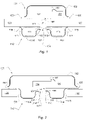
FIG. 1 shows a cross-sectional view of a microphone assembly including a filter housing and a microphone arranged at opposite sides of a circuit board, -
FIG. 2 shows a cross-sectional view of a microphone assembly including a filter housing attached to a microphone, -
FIG. 3 shows a cross-sectional view of a microphone assembly including a filter housing arranged in a depression in a circuit board and a microphone arranged opposite the filter housing, -
FIG. 4 shows examples of frequency-gain characteristics of a microphone included in microphone assembly in different configurations including one with a Helmholtz resonator, -
FIG. 5 shows a topographic view and a 3D view of an embodiment of a single-chamber rotationally symmetrical filter housing, -
FIG. 6 shows a topographic view and a 3D view of an embodiment of a dual-chamber filter housing, -
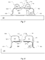
FIG. 7 shows a cross-sectional view of a microphone assembly including a filter housing atop a microphone housing, -
FIG. 8 shows a cross-sectional view of a microphone assembly including a filter housing enclosing a microphone housing, and -
FIG. 9 shows a 3D view of an exemplified listening device. - Generally, herein the term 'up' and 'down' and 'upper' and 'lower' refer to the orientation depicted in the drawing sheets. However, this is used for describing relative geometric relations more conveniently and should not limit the scope of the claims since these terms do not refer to the orientation of the elements described when used e.g. in listening devices.
-
FIG. 1 shows a cross-sectional view of a microphone assembly including afilter housing 110 and amicrophone 101 arranged at opposite sides of a carrier constituted by acircuit board 120. - The
microphone 101 has a firstacoustic port 106, which in this embodiment is arranged in asubstrate 103, such as a silicon substrate.Substrate 103 carries electronic components of the microphone on one side and is attached to thecircuit board 120 at the other side. This is a so-called bottom-port type of microphone. Thefilter housing 110 is attached to the opposite side of thecircuit board 120 and has a secondacoustic port 117. The firstacoustic port 106 and the secondacoustic port 117 are embodied as holes in thesubstrate 103 and thefilter housing 110, respectively. A bore through thecircuit board 120 establishes a portion of a firstacoustic passage 121 fluidly connecting the firstacoustic port 106 and the secondacoustic port 117. Thefilter housing 110 is substantially rotationally symmetric about aport axis 118, which is defined as a straight line extending in the direction of acoustic flow through the firstacoustic port 106 and further extending through the geometric center of the firstacoustic port 106. - Thus, the
microphone 101 is arranged at a first side of a carrier formed by thecircuit board 120, and thefilter housing 110 is arranged at a second side, opposite the first side, of the carrier. - Generally, the
microphone 101 is configured to convert acoustic waves received through the firstacoustic port 106 into an electric signal. In the microphone assembly shown, acoustic waves enter the firstacoustic passage 121 from the environment through the secondacoustic port 117. Themicrophone 101 comprises atransducer element 104 which is attached, e.g. viabonding wires 107 to anelectronic circuit 105. Theelectronic circuit 105 may include an amplifier, e.g. a preamplifier, and e.g. an analogue-to-digital (A/D) converter. Accordingly, the electric signal may be an analogue signal or a digital signal. - The
filter housing 110 has arim 119 that is attached to thecircuit board 120 such that thefilter housing 110 and thecircuit board 120 together enclose a cavity comprising the firstacoustic passage 121 as well as anacoustic chamber 111 and a secondacoustic passage 112. The secondacoustic passage 112 has a first opening into the firstacoustic passage 121 and a second opening into theacoustic chamber 111. The first opening allows the passage of acoustic waves between the firstacoustic passage 121 and the secondacoustic passage 112. The second opening allows the passage of acoustic waves between the secondacoustic passage 112 and theacoustic chamber 111. Theacoustic chamber 111 and the secondacoustic passage 112 form in unison a respective chamber and neck of a Helmholtz resonator for suppressing acoustic energy within a first frequency band in acoustic waves propagating through the firstacoustic passage 121, in particular from the secondacoustic port 117 towards the firstacoustic port 106 of the microphone. - The
acoustic chamber 111 and the secondacoustic passage 112 are thus confined by thefilter housing 110 and thecircuit board 120. It can also be seen that the secondacoustic passage 112 is narrower than theacoustic chamber 111 such that a Helmholtz resonator is formed. At the resonant frequency of the Helmholtz resonator and at adjacent frequencies, excessive movement of air through theneck 112 as well as excessive compression and decompression of air within theacoustic chamber 111 causes acoustic energy to dissipate as thermal energy, such that a portion of the acoustic energy entering theneck 112 is removed, thereby suppressing acoustic energy in acoustic waves propagating through the firstacoustic passage 121. - The resonant frequency of a Helmholtz resonator is given by the below well-known expression:

FIG. 1 , the length of the neck equals the horizontal extension (orthogonal to the port axis 118) of the secondacoustic passage 112 approximately indicated by the dashedbox 112. The cross-sectional area of the neck equals the average cross-sectional area of the secondacoustic passage 112 seen radially from theport axis 118, which may be approximated by a value somewhere between the cross-sectional area of the first opening (into the first acoustic passage 121) of the secondacoustic passage 112 and the cross-sectional area of the second opening (into the acoustic chamber 111) of the secondacoustic passage 112. The cross-sectional area of the neck may thus be computed from the radially inner diameter of the secondacoustic passage 112, the radially outer diameter of the secondacoustic passage 112, and the height (parallel to the port axis 118) of the secondacoustic passage 112. The height equals the distance between thefilter housing 110 and thecircuit board 120 at theneck portion 112. The volume of theacoustic chamber 111 can be computed by considering the dashed box atreference numeral 111 as a rotationally symmetric volume. As can be seen theacoustic chamber 111 is established between amain portion 114 of thefilter housing 110 and thecircuit board 120. At its periphery, theacoustic chamber 111 is confined by acircumferential skirt 113 of thefilter housing 110. Centrally, theacoustic chamber 111 narrows into the secondacoustic passage 112. -
FIG. 2 shows a cross-sectional view of a microphone assembly including afilter housing 110 with arim 119 attached to a carrier constituted by asubstrate 103 of amicrophone 101. Also in this view, thefilter housing 110 is substantially rotationally symmetric about theport axis 118. - In this embodiment the
circuit board 120 has a bore; wherein the bore at least partially accommodates thefilter housing 110. Thus, the bore forms a 'well' with a sufficiently wide cross-section, e.g. substantially circular or rectangular, that the filter housing can be lowered into and be at least partially accommodated in the bore. Themain portion 114 of the filter housing may be at a flush level with the lower surface of thecircuit board 120 or it may be lower or higher. - As can be seen, the
microphone 101 and in particular itssubstrate 103 has an overhang portion with respect to thefilter housing 110. This may be useful if themicrophone 101 generally has a wider footprint compared to thefilter housing 110. To establish electric connection between themicrophone 101 and thecircuit board 120, themicrophone 101 may be configured with metal pads at the overhang portion. That is, metal pads are arranged at the underside of the overhang and corresponding metal pads are arranged accordingly on the upper side of thecircuit board 120. - Albeit closely resembling the filter housing shown in
FIG. 1 , there is left more space inFIG. 2 for reference numerals referring in more detail to the shape of thefilter housing 110, in particular its central portion. The central portion has a depression formed by acentral skirt 115 extending from themain portion 114 towards thesubstrate 103 and terminating in aflange 116 surrounding the secondacoustic port 117 at a distance from thesubstrate 103. Thus, theflange 116 and thesubstrate 103 are at a distance from each other and form opposite sides of the the second acoustic passage 112 (seeFIG. 1 ). Thecentral skirt 115 centrally confines the acoustic chamber 111 (seeFIG. 1 ) of the Helmholtz resonator and narrows the secondacoustic passage 112 relative to theacoustic chamber 111. The secondacoustic passage 112 is thus formed in the space defined between theflange 116 and thesubstrate 103. As inFIG. 1 , the secondacoustic passage 112 has a first opening into the firstacoustic passage 121 and a second opening into theacoustic chamber 111. In some examples, theflange 116 or at least a portion of theflange 116 and thesubstrate 103 are substantially parallel. - In some examples, not shown, the
filter housing 110 may be an integral portion of thecircuit board 120. In such examples, thefilter housing 110 may be manufactured by forming a recess in the upper surface of thecircuit board 120 with a diameter similar to the diameter of the bore shown inFIG. 2 and letting the bottom of the recess extend radially inwards to a central bore constituting the secondacoustic port 117. Thecircuit board 120 may thus equal a vertically flipped version of thecircuit board 120 shown inFIG. 3 . The depth of the radially inner portion of the recess may be less than the depth of the radially outer portion of the recess, such that the recess contributes to the narrowing of the secondacoustic passage 112. Additionally, or alternatively, the radially inner portion of the recess may be met by a corresponding raised portion of thesubstrate 103. For instance, the raised part of thesubstrate 103 may be a hollow cylinder with a wall thickness corresponding to the length of the secondacoustic passage 112. In other words, the shape of any one, or both, of thecarrier 103 and thefilter housing 110 may be adapted to define the properties of theHelmholtz resonator -
FIG. 3 shows a cross-sectional view of a microphone assembly including afilter housing 110 arranged in a depression in a carrier constituted by acircuit board 120 and further including amicrophone 101 arranged opposite thefilter housing 110. In this embodiment, thecircuit board 120 has a recess that at least partially accommodates thefilter housing 110. Thus, the recess forms a 'well' with a sufficiently wide cross-section e.g. substantially circular or rectangular, that thefilter housing 110 can be inserted into and be at least partially accommodated in the recess. Therim 119 of thefilter housing 110 is attached to thecircuit board 120 within the recess. In some examples, therim 119 of thefilter housing 110 is attached at a bottom portion of the recess. In some examples, therim 119 of thefilter housing 110 is attached at a side portion and/or wall portion of the recess. Themain portion 114 of the filter housing may be at a flush level with the lower surface of thecircuit board 120 or it may be lower or higher. - In some examples the filter housing, here designated 310 and illustrated by dashed lines, may be flatter. In such examples, the
rim 119 of thefilter housing 310 may instead be attached to thecircuit board 120 at a periphery of the recess, e.g. outside the recess. Thus, filterhousing 310 is an alternative to filterhousing 110.Filter housing 310 may have the advantage of even better utilizing available space and allowing compact integration. - In some examples, not shown, the filter housing does not have a
circumferential skirt 113 but rather has a flat or disk-like shape. Arim 119 of the filter housing is attached to thecircuit board 120 at a periphery of the recess, outside the recess in a manner similar to thealternative filter housing 310. - In some examples, not shown, the
central skirt 115 of thefilter housing circuit board 120 is ring-shaped such that the depth of the radially inner portion of the recess is less than the depth of the radially outer portion of the recess - or even negative, such that the recess contributes to the narrowing of the secondacoustic passage 112. The secondacoustic passage 112 may further be bounded by a combination of an extruding part and theinner depression 115 of thefilter housing carrier 120 and thefilter housing Helmholtz resonator - Also in this example, the second
acoustic passage 112 has a first opening into the firstacoustic passage 121 and a second opening into theacoustic chamber 111. In such examples, the position of the first opening of the secondacoustic passage 112 can be arranged at varying distances from themicrophone 101. -
FIG. 4 shows examples of frequency-gain characteristics of amicrophone 101 included in a microphone assembly in different configurations including one with acarrier filter housing Helmholtz resonator - For comparison, the characteristic 402 is for a
microphone 101 included in a microphone assembly, however without aHelmholtz resonator - The frequency-
gain characteristic 401 represents amicrophone 101 included in a microphone assembly including acarrier filter housing Helmholtz resonator Helmholtz resonator Helmholtz resonator - However, an improvement is illustrated by the frequency-
gain characteristic 403, which represents amicrophone 101 included in a microphone assembly including acarrier filter housing Helmholtz resonator Helmholtz resonator FIG. 1 ), e.g. at a lower or an upper surface of thesubstrate 103, or at other locations between the secondacoustic passage 112 and the firstacoustic port 106, such as e.g. in or at the bore in thecircuit board 120. Thereby, as frequency-gain characteristic 403 exhibits, the peak is significantly dampened. In this example the peak is dampened by about 15 dB with respect to the frequency-gain characteristic 401. Thereby, the microphone assembly achieves significant suppression of ultrasonic signals, while substantially avoiding the excessive peak below the resonant frequency of theHelmholtz resonator - In some embodiments, the air-permeable filter member has an airflow resistance of about 280 RaylMKS or an airflow resistance in the range from 100 to 500 RaylMKS. This has the advantage of dampening a resonance peak that may occur below the resonant frequency of a Helmholtz resonator dimensioned for suppression of ultrasonic frequencies.
- The legend in the figure refers to "HHR can w/o filter", which refers to characteristic 401 and is shorthand for the microphone assembly including the
Helmholtz resonator Helmholtz resonator microphone 101 mounted on acircuit board 120 and not including the Helmholtz resonator. -
FIG. 5 shows a topographic view and a 3D view of a single-chamber rotationallysymmetrical filter housing 110. Here it is also shown that the central portion, here designated 502 has a depression formed by thecentral skirt 115 extending from themain portion 114 towards thecarrier 103, 120 (not shown here) and terminating in aflange 116 surrounding the secondacoustic port 117 at a distance from thecarrier flange 116 and thecarrier FIGs. 1 and 2 ). Thecentral skirt 115 confines the acoustic chamber 111 (seeFIG. 1 ) of the Helmholtz resonator centrally and narrows the secondacoustic passage 112 relative to theacoustic chamber 111. The secondacoustic passage 112 is thus formed in the space defined between theflange 116 and thecarrier peripheral skirt 113 extending from themain portion 114 to and terminating at arim 119 can be seen. The filter housing can be attached to thecarrier rim 119. -
FIG. 6 shows a topographic view and a perspective view of a dual-chamber filter housing 110. The embodiment shown here differs from the previously described embodiments by including an additional Helmholtz resonator with an additional chamber and a corresponding additional neck portion. - Thus, with respect to the left-hand side of
FIG. 6 , a first Helmholtz resonator is formed by a firstacoustic chamber 602 and a first neck portion oracoustic passage 604. A second Helmholtz resonator is formed by a secondacoustic chamber 603 and a second neck portion oracoustic passage 605. The first Helmholtz resonator and the second Helmholtz resonator are each in fluid connection with the secondacoustic port 117. The first and secondacoustic chambers portion 601, which can be seen also in the perspective view on the right-hand side ofFIG. 6 . - Also here it can be seen that the
filter housing 110 has aninner portion 501 surrounded by thecircumferential skirt 113 extending to therim 119 at which the filter housing can be attached to acarrier inner portion 501, or rather - in this embodiment - a portion thereof, is raised away from thecarrier acoustic chambers carrier inner portion 501. The first and secondacoustic chambers circumferential skirt 113. - In this embodiment in particular, the
inner portion 501 of thefilter housing 110 has a debossedportion 601 with a trough running from thecircumferential skirt 113 towards the secondacoustic port 117 and reaching thecarrier acoustic chamber 602 and the secondacoustic chamber 603. Further, the debossedportion 601 confines the first and secondacoustic passages acoustic chamber 602 and the secondacoustic port 117 and the secondacoustic chamber 603 and the secondacoustic port 117, such that the firstacoustic passage 604 is narrower than the firstacoustic chamber 602 and the secondacoustic passage 605 is narrower than the secondacoustic chamber 603. Thereby, an additional Helmholtz resonator is implemented. In a similar manner, further Helmholtz resonators can be implemented. -
FIG. 7 shows a cross-sectional view of a microphone assembly including afilter housing 110 atop amicrophone housing 102. In this embodiment, themicrophone 101 includes amicrophone housing 102 with a top portion surrounded by a downwardly extending peripheral skirt. The firstacoustic port 106 extends through the top portion and themicrophone 101 is thus a so-called top-port microphone. Themicrophone housing 102 is attached to a first side of thesubstrate 103, e.g. a substrate. Thefilter housing 110 is arranged atop themicrophone housing 102, and therim 119 of thefilter housing 110 is attached to the top portion such that it surrounds firstacoustic port 106. In this example, the carrier is constituted by themicrophone housing 102 that together with thefilter housing 110 enclose the cavity that comprises theHelmholtz resonator acoustic passage 121. - In some examples, the
rim 119 of thefilter housing 110 is attached to the downwardly extending peripheral skirt of themicrophone housing 102 e.g. at a side wall of themicrophone housing 102. -
FIG. 8 shows a cross-sectional view of a microphone assembly including afilter housing 110 enclosing amicrophone housing 102. Also, in this embodiment themicrophone 101 includes amicrophone housing 102 with a top portion surrounded by a downwardly extending peripheral skirt. The firstacoustic port 106 extends through the top portion and themicrophone 101 is thus a so-called top-port microphone. Themicrophone housing 102 is attached to a first side of thesubstrate 103, e.g. a silicon substrate. Thefilter housing 110 is arranged over themicrophone housing 102, and therim 119 of thefilter housing 110 is attached to the first side of thesubstrate 103. In this example, the carrier is constituted by thesubstrate 103 and themicrophone housing 102 that together with thefilter housing 110 enclose the cavity that comprises theHelmholtz resonator acoustic passage 121. - Generally, two or more acoustic filters with Helmholtz resonators as described above may be stacked, such that acoustic waves from the environment travels through several first
acoustic passages 121 extends, each with their own individually tuned Helmholtz resonator(s). In some examples, therim 119 of afurther filter housing 110 may be attached to the main portion of anotherfilter housing 110. In some examples, therim 119 of afurther filter housing 110 may be attached to asilicon substrate 103 or acircuit board 120 thereby enclosing anotherfilter housing 110. - Generally, herein, one or both of the
filter housing 110 and themicrophone housing 102 may have a substantially round or substantially rectangular cross-sectional shape or any other shape that serves the purpose of at least partly enclosing the cavity that comprises theHelmholtz resonator -
FIG. 9 shows an example of a pair of listening devices comprising a right-ear device 905 and a left-ear device 906. Thelistening devices body 902. Each of the listening devices may have one, two or more microphone assemblies as described herein. To receive acoustic waves from the surroundings, each of the listening devices has one or moresmall holes 903 allowing passage of acoustic waves from the environment to the respective secondacoustic ports 117 of the comprised microphone assemblies. - In some examples, listening devices comprising a microphone assembly as described herein are configured to one or more of: compensating for a hearing loss, protecting against loud sound levels in the surroundings, playing back audio signals, and/or operating as a headset for telecommunication.
- At least in examples wherein the listening device is configured to compensate for a hearing loss, the listening device may be of e.g. a so-called Receiver-in-Ear (RIE) type, Behind the Ear (BTE) type, Completely-in-Canal (CIC) type or of another type known in the art of hearing devices including hearing aids. For other uses, the listening device may be of e.g. a so-called earbud type, an on-the-ear earphone type, or an over-the-ear earphone type. Furthermore, the listening device may be configured as a monaural listening device or as a binaural listening device.
Claims (15)
- A microphone assembly comprising:- a microphone (101) with a first acoustic port (106), wherein the microphone (101) is configured to convert acoustic waves received through the first acoustic port (106) into an electric signal;- a filter housing (110) with a second acoustic port (117) and a rim (119); and- a carrier (102, 103, 120) attached to the microphone (101) and to the rim (119) of the filter housing (110) such that the carrier (102, 103, 120) and the filter housing (110) together enclose a cavity with a first acoustic passage (121) fluidly connecting the first acoustic port (106) and the second acoustic port (117) thereby enabling acoustic waves to propagate from the second acoustic port (117) through the first acoustic passage (121) to the first acoustic port (106), whereby a port axis (118) is defined as a straight line extending in the direction of acoustic flow through the first acoustic port (106) and further extending through the geometric center of the first acoustic port (106),
characterized in that:- the carrier (102, 103, 120) and the filter housing (110) are configured to cause the cavity to comprise an acoustic chamber (111) and a second acoustic passage (112), wherein the second acoustic passage (112) has a first opening into the first acoustic passage (121) and a second opening into the acoustic chamber (111) such that the acoustic chamber (111) and the second acoustic passage (112) together establish a Helmholtz resonator for suppressing acoustic energy within a first frequency band in acoustic waves propagating through the first acoustic passage (121). - A microphone assembly according to claim 1, wherein the microphone (101) comprises a transducer element (104) for converting the received acoustic waves into the electric signal, and wherein the transducer element (104) is arranged on a first side of the carrier (102, 103, 120) and the filter housing (110) is arranged at a second side, opposite the first side, of the carrier (102, 103, 120), such that the transducer element (104) is fluidly connected to the second acoustic port (117) through the first acoustic port (106) and the first acoustic passage (121).
- A microphone assembly according to claim 1 or 2, wherein the direction of acoustic flow through the second acoustic port (117) is parallel to the port axis (118), and/or wherein the port axis (118) extends through the second acoustic port (117), preferably through the geometric center of the second acoustic port (117).
- A microphone assembly according to any of the preceding claims, wherein the carrier (103, 120) has a bore enclosing at least a portion of the first acoustic passage (121), and wherein a center axis of the bore coincides with the port axis (118).
- A microphone assembly according to any of the preceding claims, wherein the filter housing (110) comprises an inner portion (501) with a central portion (502) that has a depression (503) formed by a central skirt (115) extending towards the carrier (102, 103, 120) and terminating in a flange (116) surrounding the second acoustic port (117) at a distance from the carrier (102, 103, 120).
- A microphone assembly according to any of the preceding claims, wherein the filter housing (110) comprises an inner portion (501) surrounded by a circumferential skirt (113) extending to the rim (119).
- A microphone assembly according to any of the preceding claims, wherein the filter housing (110) is rotationally symmetric with respect to the port axis (118).
- A microphone assembly according to claim 6, wherein:- the inner portion (501) of the filter housing (110) has at least one debossed portion (601) with a trough running from the circumferential skirt (113) towards the second acoustic port (117) and reaching the carrier (102, 103, 120) at the trough such that in addition to the acoustic chamber (111, 602) and the second acoustic passage (112, 604) the cavity comprises a further acoustic chamber (603) and a further acoustic passage (605); and- the further acoustic passage (605) has a first opening into the first acoustic passage (121) and a second opening into the further acoustic chamber (603) such that the further acoustic chamber (603) and the further acoustic passage (605) together establish a further Helmholtz resonator for suppressing acoustic energy within a second frequency band, different from the first frequency band, in acoustic waves propagating through the first acoustic passage (121).
- A microphone assembly according to any of the preceding claims, wherein the filter housing (110) is a shaped piece of metal, and wherein the rim (119) is attached to the carrier (102, 103, 120) by a solder material or glue.
- A microphone assembly according to any of the preceding claims, further comprising an air-permeable filter member dampening acoustic energy at least at a frequency below the resonant frequency of the Helmholtz resonator, wherein the air-permeable member is arranged inside or at the first acoustic port (106).
- A microphone assembly according to any of the preceding claims, wherein the carrier comprises a silicon substrate (103) and/or a circuit board (120).
- A microphone assembly according to claim 11, wherein the carrier (103, 120) has a recess or bore, and wherein the recess or bore completely or partially accommodates the filter housing (110).
- A microphone assembly according to any of the preceding claims, wherein the carrier comprises a silicon substrate (103) and/or a microphone housing (102).
- A microphone assembly according to claim 13, wherein:- the microphone (101) comprises a silicon substrate (103) and a microphone housing (102) with a top portion surrounded by peripheral skirt extending downwards to the silicon substrate (103);- the first acoustic port (106) extends through the top portion;- the microphone housing (102) is attached to a first side of the silicon substrate (103);- the carrier comprises the microphone housing (102); and- the filter housing (110) is arranged at the first side of the silicon substrate (103) on or around the microphone housing (102).
- A listening device comprising at least one microphone assembly according to any of the preceding claims.
Priority Applications (4)
| Application Number | Priority Date | Filing Date | Title |
|---|---|---|---|
| EP20218015.4A EP4024890B8 (en) | 2020-12-31 | 2020-12-31 | Microphone assembly with acoustic filter |
| US17/549,858 US11800278B2 (en) | 2020-12-31 | 2021-12-13 | Microphone assembly with acoustic filter |
| JP2021206499A JP2022105287A (en) | 2020-12-31 | 2021-12-20 | Microphone assembly with acoustic filter |
| CN202111671937.8A CN114697781A (en) | 2020-12-31 | 2021-12-31 | Microphone assembly with acoustic filter |
Applications Claiming Priority (1)
| Application Number | Priority Date | Filing Date | Title |
|---|---|---|---|
| EP20218015.4A EP4024890B8 (en) | 2020-12-31 | 2020-12-31 | Microphone assembly with acoustic filter |
Publications (4)
| Publication Number | Publication Date |
|---|---|
| EP4024890A1 true EP4024890A1 (en) | 2022-07-06 |
| EP4024890B1 EP4024890B1 (en) | 2024-12-18 |
| EP4024890C0 EP4024890C0 (en) | 2024-12-18 |
| EP4024890B8 EP4024890B8 (en) | 2025-01-22 |
Family
ID=74129971
Family Applications (1)
| Application Number | Title | Priority Date | Filing Date |
|---|---|---|---|
| EP20218015.4A Active EP4024890B8 (en) | 2020-12-31 | 2020-12-31 | Microphone assembly with acoustic filter |
Country Status (4)
| Country | Link |
|---|---|
| US (1) | US11800278B2 (en) |
| EP (1) | EP4024890B8 (en) |
| JP (1) | JP2022105287A (en) |
| CN (1) | CN114697781A (en) |
Families Citing this family (5)
| Publication number | Priority date | Publication date | Assignee | Title |
|---|---|---|---|---|
| WO2021152922A1 (en) * | 2020-01-27 | 2021-08-05 | パナソニック インテレクチュアル プロパティ コーポレーション オブ アメリカ | Sound pickup device |
| US12244990B2 (en) * | 2022-09-01 | 2025-03-04 | Apple Inc. | Acoustic vent and protective membrane |
| US12133038B2 (en) | 2022-09-01 | 2024-10-29 | Apple Inc. | Acoustic vent and protective membrane |
| US20250113138A1 (en) * | 2023-09-29 | 2025-04-03 | Apple Inc. | Wideband Sub-Wavelength Chip-Scale Acoustic Wave Attenuators |
| US20250267392A1 (en) * | 2024-02-19 | 2025-08-21 | Starkey Laboratories, Inc. | Ear-wearable electronic device including acoustic filter |
Citations (7)
| Publication number | Priority date | Publication date | Assignee | Title |
|---|---|---|---|---|
| US20120027240A1 (en) * | 2009-12-30 | 2012-02-02 | Foxconn Technology Co., Ltd. | Microphone module with helmholtz resonance chamber |
| CN202663539U (en) * | 2012-05-25 | 2013-01-09 | 歌尔声学股份有限公司 | MEMS (micro-electro-mechanical system) microphone |
| US20130034257A1 (en) * | 2011-08-02 | 2013-02-07 | Robert Bosch Gmbh | Mems microphone |
| US20130129136A1 (en) | 2011-11-17 | 2013-05-23 | Analog Devices, Inc. | Microphone Module with Sound Pipe |
| WO2018026657A1 (en) * | 2016-08-02 | 2018-02-08 | Knowles Electronics, Llc | Mems ultrasonic transducer |
| US20180233827A1 (en) * | 2017-02-15 | 2018-08-16 | Wildlife Acoustics, Inc. | Ultrasonic microphone enclosure |
| KR20200040958A (en) * | 2018-10-10 | 2020-04-21 | 싸니코전자 주식회사 | Directional MEMS microphone and MEMS microphone module comprising it |
Family Cites Families (10)
| Publication number | Priority date | Publication date | Assignee | Title |
|---|---|---|---|---|
| CH528197A (en) * | 1971-12-20 | 1972-09-15 | Ibm | Housing arrangement with an electro-acoustic transducer, and use of the same in a telephone set of a communication system with PCM coding |
| US20130070950A1 (en) * | 2009-12-30 | 2013-03-21 | Hwang-Miaw Chen | Microphone module with helmholtz resonance chamber |
| CN103096197A (en) * | 2011-11-08 | 2013-05-08 | 富准精密工业(深圳)有限公司 | Microphone module |
| US20140294182A1 (en) * | 2013-03-28 | 2014-10-02 | Cirrus Logic, Inc. | Systems and methods for locating an error microphone to minimize or reduce obstruction of an acoustic transducer wave path |
| GB2561020B (en) * | 2017-03-30 | 2020-04-22 | Cirrus Logic Int Semiconductor Ltd | Apparatus and methods for monitoring a microphone |
| US10405086B2 (en) * | 2017-11-06 | 2019-09-03 | Bose Corporation | Microphone cavity |
| WO2019099414A1 (en) * | 2017-11-14 | 2019-05-23 | Knowles Electronics, Llc | Sensor package with ingress protection |
| CN213718168U (en) * | 2019-12-30 | 2021-07-16 | 美商楼氏电子有限公司 | Sensor assembly |
| WO2021152922A1 (en) * | 2020-01-27 | 2021-08-05 | パナソニック インテレクチュアル プロパティ コーポレーション オブ アメリカ | Sound pickup device |
| EP4090049B1 (en) * | 2021-05-11 | 2024-12-11 | Infineon Technologies AG | Mems device with passive acoustic attenuation filter |
-
2020
- 2020-12-31 EP EP20218015.4A patent/EP4024890B8/en active Active
-
2021
- 2021-12-13 US US17/549,858 patent/US11800278B2/en active Active
- 2021-12-20 JP JP2021206499A patent/JP2022105287A/en active Pending
- 2021-12-31 CN CN202111671937.8A patent/CN114697781A/en active Pending
Patent Citations (7)
| Publication number | Priority date | Publication date | Assignee | Title |
|---|---|---|---|---|
| US20120027240A1 (en) * | 2009-12-30 | 2012-02-02 | Foxconn Technology Co., Ltd. | Microphone module with helmholtz resonance chamber |
| US20130034257A1 (en) * | 2011-08-02 | 2013-02-07 | Robert Bosch Gmbh | Mems microphone |
| US20130129136A1 (en) | 2011-11-17 | 2013-05-23 | Analog Devices, Inc. | Microphone Module with Sound Pipe |
| CN202663539U (en) * | 2012-05-25 | 2013-01-09 | 歌尔声学股份有限公司 | MEMS (micro-electro-mechanical system) microphone |
| WO2018026657A1 (en) * | 2016-08-02 | 2018-02-08 | Knowles Electronics, Llc | Mems ultrasonic transducer |
| US20180233827A1 (en) * | 2017-02-15 | 2018-08-16 | Wildlife Acoustics, Inc. | Ultrasonic microphone enclosure |
| KR20200040958A (en) * | 2018-10-10 | 2020-04-21 | 싸니코전자 주식회사 | Directional MEMS microphone and MEMS microphone module comprising it |
Also Published As
| Publication number | Publication date |
|---|---|
| EP4024890B8 (en) | 2025-01-22 |
| EP4024890B1 (en) | 2024-12-18 |
| JP2022105287A (en) | 2022-07-13 |
| US20220210547A1 (en) | 2022-06-30 |
| CN114697781A (en) | 2022-07-01 |
| EP4024890C0 (en) | 2024-12-18 |
| US11800278B2 (en) | 2023-10-24 |
Similar Documents
| Publication | Publication Date | Title |
|---|---|---|
| US11800278B2 (en) | Microphone assembly with acoustic filter | |
| US8170249B2 (en) | Hearing aid having two receivers each amplifying a different frequency range | |
| CN109511028B (en) | Multi-driver earplug | |
| EP4040799B1 (en) | Microphone and speaker combined module, earphones, and terminal device | |
| US6681022B1 (en) | Two-way communication earpiece | |
| US20190208301A1 (en) | Audio device with acoustic valve | |
| EP2405674B1 (en) | A hearing aid with occlusion reduction | |
| JP7130058B2 (en) | Device and method for removing vibration of dual-microphone earphone | |
| US20070223735A1 (en) | Electroacoustic Transducer System and Manufacturing Method Thereof | |
| US20070230734A1 (en) | Monitor Transducer System and Manufacturing Method Thereof | |
| US9872112B2 (en) | Noise mitigating microphone system | |
| US20100128905A1 (en) | Personal listening device | |
| US8731231B2 (en) | Dynamic sound transducer and receiver | |
| JP2021034775A (en) | earphone | |
| EP3471434A1 (en) | Hearing aid having a microphone module with improved ultrasound properties | |
| US7076074B2 (en) | Bearing of an electroacoustic miniature transducer in a device, particularly a hearing aid device, as well as an electroacoustic miniature transducer | |
| CN112913256A (en) | Double layer microphone protection | |
| EP3664466A1 (en) | An earphone with an active noise cancelling feedback microphone arranged at the rear-side of a speaker diaphragm and a method of manufacturing such an earphone | |
| CN212435899U (en) | Noise reduction assembly and earphone | |
| WO2016098382A1 (en) | Earphone microphone to be worn in external auditory meatus | |
| CN1985543A (en) | Apparatus for suppressing radio frequency interference in a microphone assembly with preamplifier | |
| EP2733956B1 (en) | Methods for wideband receiver and module for a hearing assistance device | |
| EP2786592B1 (en) | Electro-acoustic transducer for mounting on a substrate | |
| EP4231662A1 (en) | Hearing device with active noise control | |
| US20050152566A1 (en) | Electric to acoustic transducer for a hearing aid |
Legal Events
| Date | Code | Title | Description |
|---|---|---|---|
| PUAI | Public reference made under article 153(3) epc to a published international application that has entered the european phase |
Free format text: ORIGINAL CODE: 0009012 |
|
| STAA | Information on the status of an ep patent application or granted ep patent |
Free format text: STATUS: THE APPLICATION HAS BEEN PUBLISHED |
|
| AK | Designated contracting states |
Kind code of ref document: A1 Designated state(s): AL AT BE BG CH CY CZ DE DK EE ES FI FR GB GR HR HU IE IS IT LI LT LU LV MC MK MT NL NO PL PT RO RS SE SI SK SM TR |
|
| STAA | Information on the status of an ep patent application or granted ep patent |
Free format text: STATUS: REQUEST FOR EXAMINATION WAS MADE |
|
| 17P | Request for examination filed |
Effective date: 20230106 |
|
| RBV | Designated contracting states (corrected) |
Designated state(s): AL AT BE BG CH CY CZ DE DK EE ES FI FR GB GR HR HU IE IS IT LI LT LU LV MC MK MT NL NO PL PT RO RS SE SI SK SM TR |
|
| GRAP | Despatch of communication of intention to grant a patent |
Free format text: ORIGINAL CODE: EPIDOSNIGR1 |
|
| STAA | Information on the status of an ep patent application or granted ep patent |
Free format text: STATUS: GRANT OF PATENT IS INTENDED |
|
| RIC1 | Information provided on ipc code assigned before grant |
Ipc: B81B 7/00 20060101ALI20240704BHEP Ipc: H04R 1/28 20060101AFI20240704BHEP |
|
| INTG | Intention to grant announced |
Effective date: 20240712 |
|
| GRAS | Grant fee paid |
Free format text: ORIGINAL CODE: EPIDOSNIGR3 |
|
| GRAA | (expected) grant |
Free format text: ORIGINAL CODE: 0009210 |
|
| STAA | Information on the status of an ep patent application or granted ep patent |
Free format text: STATUS: THE PATENT HAS BEEN GRANTED |
|
| REG | Reference to a national code |
Ref country code: DE Ref legal event code: R081 Ref document number: 602020043287 Country of ref document: DE Owner name: GN HEARING A/S, DK Free format text: FORMER OWNER: GN HEARING 2 A/S, BALLERUP, DK |
|
| AK | Designated contracting states |
Kind code of ref document: B1 Designated state(s): AL AT BE BG CH CY CZ DE DK EE ES FI FR GB GR HR HU IE IS IT LI LT LU LV MC MK MT NL NO PL PT RO RS SE SI SK SM TR |
|
| RAP2 | Party data changed (patent owner data changed or rights of a patent transferred) |
Owner name: GN HEARING A/S |
|
| REG | Reference to a national code |
Ref country code: CH Ref legal event code: PK Free format text: BERICHTIGUNG B8 Ref country code: CH Ref legal event code: EP |
|
| REG | Reference to a national code |
Ref country code: DE Ref legal event code: R096 Ref document number: 602020043287 Country of ref document: DE |
|
| REG | Reference to a national code |
Ref country code: IE Ref legal event code: FG4D |
|
| U01 | Request for unitary effect filed |
Effective date: 20250106 |
|
| U07 | Unitary effect registered |
Designated state(s): AT BE BG DE DK EE FI FR IT LT LU LV MT NL PT RO SE SI Effective date: 20250116 |
|
| PG25 | Lapsed in a contracting state [announced via postgrant information from national office to epo] |
Ref country code: HR Free format text: LAPSE BECAUSE OF FAILURE TO SUBMIT A TRANSLATION OF THE DESCRIPTION OR TO PAY THE FEE WITHIN THE PRESCRIBED TIME-LIMIT Effective date: 20241218 |
|
| PG25 | Lapsed in a contracting state [announced via postgrant information from national office to epo] |
Ref country code: NO Free format text: LAPSE BECAUSE OF FAILURE TO SUBMIT A TRANSLATION OF THE DESCRIPTION OR TO PAY THE FEE WITHIN THE PRESCRIBED TIME-LIMIT Effective date: 20250318 |
|
| PG25 | Lapsed in a contracting state [announced via postgrant information from national office to epo] |
Ref country code: GR Free format text: LAPSE BECAUSE OF FAILURE TO SUBMIT A TRANSLATION OF THE DESCRIPTION OR TO PAY THE FEE WITHIN THE PRESCRIBED TIME-LIMIT Effective date: 20250319 |
|
| PG25 | Lapsed in a contracting state [announced via postgrant information from national office to epo] |
Ref country code: RS Free format text: LAPSE BECAUSE OF FAILURE TO SUBMIT A TRANSLATION OF THE DESCRIPTION OR TO PAY THE FEE WITHIN THE PRESCRIBED TIME-LIMIT Effective date: 20250318 |
|
| U20 | Renewal fee for the european patent with unitary effect paid |
Year of fee payment: 5 Effective date: 20250414 |
|
| PG25 | Lapsed in a contracting state [announced via postgrant information from national office to epo] |
Ref country code: SM Free format text: LAPSE BECAUSE OF FAILURE TO SUBMIT A TRANSLATION OF THE DESCRIPTION OR TO PAY THE FEE WITHIN THE PRESCRIBED TIME-LIMIT Effective date: 20241218 |
|
| PG25 | Lapsed in a contracting state [announced via postgrant information from national office to epo] |
Ref country code: PL Free format text: LAPSE BECAUSE OF FAILURE TO SUBMIT A TRANSLATION OF THE DESCRIPTION OR TO PAY THE FEE WITHIN THE PRESCRIBED TIME-LIMIT Effective date: 20241218 |
|
| PG25 | Lapsed in a contracting state [announced via postgrant information from national office to epo] |
Ref country code: ES Free format text: LAPSE BECAUSE OF FAILURE TO SUBMIT A TRANSLATION OF THE DESCRIPTION OR TO PAY THE FEE WITHIN THE PRESCRIBED TIME-LIMIT Effective date: 20241218 |
|
| PG25 | Lapsed in a contracting state [announced via postgrant information from national office to epo] |
Ref country code: IS Free format text: LAPSE BECAUSE OF FAILURE TO SUBMIT A TRANSLATION OF THE DESCRIPTION OR TO PAY THE FEE WITHIN THE PRESCRIBED TIME-LIMIT Effective date: 20250418 |
|
| PG25 | Lapsed in a contracting state [announced via postgrant information from national office to epo] |
Ref country code: SK Free format text: LAPSE BECAUSE OF FAILURE TO SUBMIT A TRANSLATION OF THE DESCRIPTION OR TO PAY THE FEE WITHIN THE PRESCRIBED TIME-LIMIT Effective date: 20241218 |
|
| PG25 | Lapsed in a contracting state [announced via postgrant information from national office to epo] |
Ref country code: CZ Free format text: LAPSE BECAUSE OF FAILURE TO SUBMIT A TRANSLATION OF THE DESCRIPTION OR TO PAY THE FEE WITHIN THE PRESCRIBED TIME-LIMIT Effective date: 20241218 |
|
| PG25 | Lapsed in a contracting state [announced via postgrant information from national office to epo] |
Ref country code: MC Free format text: LAPSE BECAUSE OF FAILURE TO SUBMIT A TRANSLATION OF THE DESCRIPTION OR TO PAY THE FEE WITHIN THE PRESCRIBED TIME-LIMIT Effective date: 20241218 |
|
| PG25 | Lapsed in a contracting state [announced via postgrant information from national office to epo] |
Ref country code: IE Free format text: LAPSE BECAUSE OF NON-PAYMENT OF DUE FEES Effective date: 20241231 |
|
| PLBE | No opposition filed within time limit |
Free format text: ORIGINAL CODE: 0009261 |
|
| STAA | Information on the status of an ep patent application or granted ep patent |
Free format text: STATUS: NO OPPOSITION FILED WITHIN TIME LIMIT |
|
| REG | Reference to a national code |
Ref country code: CH Ref legal event code: L10 Free format text: ST27 STATUS EVENT CODE: U-0-0-L10-L00 (AS PROVIDED BY THE NATIONAL OFFICE) Effective date: 20251029 |
|
| 26N | No opposition filed |
Effective date: 20250919 |
|
| REG | Reference to a national code |
Ref country code: CH Ref legal event code: U11 Free format text: ST27 STATUS EVENT CODE: U-0-0-U10-U11 (AS PROVIDED BY THE NATIONAL OFFICE) Effective date: 20260101 |
|
| PGFP | Annual fee paid to national office [announced via postgrant information from national office to epo] |
Ref country code: GB Payment date: 20251219 Year of fee payment: 6 |
|
| U20 | Renewal fee for the european patent with unitary effect paid |
Year of fee payment: 6 Effective date: 20251216 |
|
| PGFP | Annual fee paid to national office [announced via postgrant information from national office to epo] |
Ref country code: CH Payment date: 20260101 Year of fee payment: 6 |
|
| PG25 | Lapsed in a contracting state [announced via postgrant information from national office to epo] |
Ref country code: CY Free format text: LAPSE BECAUSE OF FAILURE TO SUBMIT A TRANSLATION OF THE DESCRIPTION OR TO PAY THE FEE WITHIN THE PRESCRIBED TIME-LIMIT Effective date: 20241218 |