EP4024593A1 - Battery module, battery pack comprising same, and vehicle - Google Patents
Battery module, battery pack comprising same, and vehicle Download PDFInfo
- Publication number
- EP4024593A1 EP4024593A1 EP21807642.0A EP21807642A EP4024593A1 EP 4024593 A1 EP4024593 A1 EP 4024593A1 EP 21807642 A EP21807642 A EP 21807642A EP 4024593 A1 EP4024593 A1 EP 4024593A1
- Authority
- EP
- European Patent Office
- Prior art keywords
- battery module
- gas
- pipe
- gas pipe
- insertion hole
- Prior art date
- Legal status (The legal status is an assumption and is not a legal conclusion. Google has not performed a legal analysis and makes no representation as to the accuracy of the status listed.)
- Pending
Links
- 238000004891 communication Methods 0.000 claims abstract description 8
- 238000007789 sealing Methods 0.000 claims description 44
- 238000003780 insertion Methods 0.000 claims description 39
- 230000037431 insertion Effects 0.000 claims description 39
- 239000002360 explosive Substances 0.000 claims description 15
- 238000004880 explosion Methods 0.000 abstract description 14
- 239000007789 gas Substances 0.000 description 128
- 238000004519 manufacturing process Methods 0.000 description 8
- WHXSMMKQMYFTQS-UHFFFAOYSA-N Lithium Chemical compound [Li] WHXSMMKQMYFTQS-UHFFFAOYSA-N 0.000 description 6
- 229910052744 lithium Inorganic materials 0.000 description 6
- PXHVJJICTQNCMI-UHFFFAOYSA-N Nickel Chemical compound [Ni] PXHVJJICTQNCMI-UHFFFAOYSA-N 0.000 description 4
- 230000008901 benefit Effects 0.000 description 4
- 229910052751 metal Inorganic materials 0.000 description 4
- 239000002184 metal Substances 0.000 description 4
- 230000007423 decrease Effects 0.000 description 3
- 229910052782 aluminium Inorganic materials 0.000 description 2
- XAGFODPZIPBFFR-UHFFFAOYSA-N aluminium Chemical compound [Al] XAGFODPZIPBFFR-UHFFFAOYSA-N 0.000 description 2
- 239000013013 elastic material Substances 0.000 description 2
- 239000000463 material Substances 0.000 description 2
- 238000012986 modification Methods 0.000 description 2
- 230000004048 modification Effects 0.000 description 2
- 239000007773 negative electrode material Substances 0.000 description 2
- 229910052759 nickel Inorganic materials 0.000 description 2
- 238000004806 packaging method and process Methods 0.000 description 2
- 239000004033 plastic Substances 0.000 description 2
- 239000007774 positive electrode material Substances 0.000 description 2
- RYGMFSIKBFXOCR-UHFFFAOYSA-N Copper Chemical compound [Cu] RYGMFSIKBFXOCR-UHFFFAOYSA-N 0.000 description 1
- 244000043261 Hevea brasiliensis Species 0.000 description 1
- 239000000853 adhesive Substances 0.000 description 1
- 230000001070 adhesive effect Effects 0.000 description 1
- OJIJEKBXJYRIBZ-UHFFFAOYSA-N cadmium nickel Chemical compound [Ni].[Cd] OJIJEKBXJYRIBZ-UHFFFAOYSA-N 0.000 description 1
- 239000003575 carbonaceous material Substances 0.000 description 1
- 229910052802 copper Inorganic materials 0.000 description 1
- 239000010949 copper Substances 0.000 description 1
- 230000003247 decreasing effect Effects 0.000 description 1
- 238000011161 development Methods 0.000 description 1
- 230000000694 effects Effects 0.000 description 1
- 239000008151 electrolyte solution Substances 0.000 description 1
- 238000004146 energy storage Methods 0.000 description 1
- -1 for example Substances 0.000 description 1
- 229910052739 hydrogen Inorganic materials 0.000 description 1
- 239000001257 hydrogen Substances 0.000 description 1
- 230000003446 memory effect Effects 0.000 description 1
- 238000000034 method Methods 0.000 description 1
- 229920003052 natural elastomer Polymers 0.000 description 1
- 229920001194 natural rubber Polymers 0.000 description 1
- QELJHCBNGDEXLD-UHFFFAOYSA-N nickel zinc Chemical compound [Ni].[Zn] QELJHCBNGDEXLD-UHFFFAOYSA-N 0.000 description 1
- 239000000565 sealant Substances 0.000 description 1
- 229920002379 silicone rubber Polymers 0.000 description 1
- 239000004945 silicone rubber Substances 0.000 description 1
- 239000000243 solution Substances 0.000 description 1
- 229920003051 synthetic elastomer Polymers 0.000 description 1
- 239000005061 synthetic rubber Substances 0.000 description 1
Images


Classifications
-
- H—ELECTRICITY
- H01—ELECTRIC ELEMENTS
- H01M—PROCESSES OR MEANS, e.g. BATTERIES, FOR THE DIRECT CONVERSION OF CHEMICAL ENERGY INTO ELECTRICAL ENERGY
- H01M50/00—Constructional details or processes of manufacture of the non-active parts of electrochemical cells other than fuel cells, e.g. hybrid cells
- H01M50/10—Primary casings, jackets or wrappings of a single cell or a single battery
- H01M50/14—Primary casings, jackets or wrappings of a single cell or a single battery for protecting against damage caused by external factors
- H01M50/143—Fireproof; Explosion-proof
-
- H—ELECTRICITY
- H01—ELECTRIC ELEMENTS
- H01M—PROCESSES OR MEANS, e.g. BATTERIES, FOR THE DIRECT CONVERSION OF CHEMICAL ENERGY INTO ELECTRICAL ENERGY
- H01M50/00—Constructional details or processes of manufacture of the non-active parts of electrochemical cells other than fuel cells, e.g. hybrid cells
- H01M50/30—Arrangements for facilitating escape of gases
- H01M50/394—Gas-pervious parts or elements
-
- H—ELECTRICITY
- H01—ELECTRIC ELEMENTS
- H01M—PROCESSES OR MEANS, e.g. BATTERIES, FOR THE DIRECT CONVERSION OF CHEMICAL ENERGY INTO ELECTRICAL ENERGY
- H01M50/00—Constructional details or processes of manufacture of the non-active parts of electrochemical cells other than fuel cells, e.g. hybrid cells
- H01M50/30—Arrangements for facilitating escape of gases
- H01M50/35—Gas exhaust passages comprising elongated, tortuous or labyrinth-shaped exhaust passages
- H01M50/358—External gas exhaust passages located on the battery cover or case
-
- H—ELECTRICITY
- H01—ELECTRIC ELEMENTS
- H01M—PROCESSES OR MEANS, e.g. BATTERIES, FOR THE DIRECT CONVERSION OF CHEMICAL ENERGY INTO ELECTRICAL ENERGY
- H01M50/00—Constructional details or processes of manufacture of the non-active parts of electrochemical cells other than fuel cells, e.g. hybrid cells
- H01M50/20—Mountings; Secondary casings or frames; Racks, modules or packs; Suspension devices; Shock absorbers; Transport or carrying devices; Holders
- H01M50/204—Racks, modules or packs for multiple batteries or multiple cells
- H01M50/207—Racks, modules or packs for multiple batteries or multiple cells characterised by their shape
- H01M50/211—Racks, modules or packs for multiple batteries or multiple cells characterised by their shape adapted for pouch cells
-
- H—ELECTRICITY
- H01—ELECTRIC ELEMENTS
- H01M—PROCESSES OR MEANS, e.g. BATTERIES, FOR THE DIRECT CONVERSION OF CHEMICAL ENERGY INTO ELECTRICAL ENERGY
- H01M50/00—Constructional details or processes of manufacture of the non-active parts of electrochemical cells other than fuel cells, e.g. hybrid cells
- H01M50/20—Mountings; Secondary casings or frames; Racks, modules or packs; Suspension devices; Shock absorbers; Transport or carrying devices; Holders
- H01M50/271—Lids or covers for the racks or secondary casings
-
- H—ELECTRICITY
- H01—ELECTRIC ELEMENTS
- H01M—PROCESSES OR MEANS, e.g. BATTERIES, FOR THE DIRECT CONVERSION OF CHEMICAL ENERGY INTO ELECTRICAL ENERGY
- H01M50/00—Constructional details or processes of manufacture of the non-active parts of electrochemical cells other than fuel cells, e.g. hybrid cells
- H01M50/30—Arrangements for facilitating escape of gases
- H01M50/35—Gas exhaust passages comprising elongated, tortuous or labyrinth-shaped exhaust passages
-
- H—ELECTRICITY
- H01—ELECTRIC ELEMENTS
- H01M—PROCESSES OR MEANS, e.g. BATTERIES, FOR THE DIRECT CONVERSION OF CHEMICAL ENERGY INTO ELECTRICAL ENERGY
- H01M50/00—Constructional details or processes of manufacture of the non-active parts of electrochemical cells other than fuel cells, e.g. hybrid cells
- H01M50/30—Arrangements for facilitating escape of gases
- H01M50/375—Vent means sensitive to or responsive to temperature
-
- H—ELECTRICITY
- H01—ELECTRIC ELEMENTS
- H01M—PROCESSES OR MEANS, e.g. BATTERIES, FOR THE DIRECT CONVERSION OF CHEMICAL ENERGY INTO ELECTRICAL ENERGY
- H01M2200/00—Safety devices for primary or secondary batteries
-
- H—ELECTRICITY
- H01—ELECTRIC ELEMENTS
- H01M—PROCESSES OR MEANS, e.g. BATTERIES, FOR THE DIRECT CONVERSION OF CHEMICAL ENERGY INTO ELECTRICAL ENERGY
- H01M2220/00—Batteries for particular applications
- H01M2220/20—Batteries in motive systems, e.g. vehicle, ship, plane
-
- Y—GENERAL TAGGING OF NEW TECHNOLOGICAL DEVELOPMENTS; GENERAL TAGGING OF CROSS-SECTIONAL TECHNOLOGIES SPANNING OVER SEVERAL SECTIONS OF THE IPC; TECHNICAL SUBJECTS COVERED BY FORMER USPC CROSS-REFERENCE ART COLLECTIONS [XRACs] AND DIGESTS
- Y02—TECHNOLOGIES OR APPLICATIONS FOR MITIGATION OR ADAPTATION AGAINST CLIMATE CHANGE
- Y02E—REDUCTION OF GREENHOUSE GAS [GHG] EMISSIONS, RELATED TO ENERGY GENERATION, TRANSMISSION OR DISTRIBUTION
- Y02E60/00—Enabling technologies; Technologies with a potential or indirect contribution to GHG emissions mitigation
- Y02E60/10—Energy storage using batteries
Definitions
- the present disclosure relates to a battery module, a battery pack comprising the same and a vehicle, and more particularly, to a battery module with improved safety against fires or explosions.
- a lithium secondary battery primarily uses a lithium-based oxide and a carbon material as a positive electrode active material and a negative electrode active material respectively. Additionally, the lithium secondary battery includes an electrode assembly including a positive electrode plate and a negative electrode plate coated with the positive electrode active material and the negative electrode active material respectively with a separator interposed between the positive electrode plate and the negative electrode plate, and a packaging or a battery case in which the electrode assembly is hermetically received together with an electrolyte solution.
- lithium secondary batteries may be classified into can-type secondary batteries including the electrode assembly embedded in a metal can and pouch-type secondary batteries including the electrode assembly embedded in a pouch of an aluminum laminate sheet according to the shape of the packaging.
- the large capacity battery module includes a plurality of secondary batteries, and when fires or explosions occur in the plurality of secondary batteries, the fires are likely to spread to the adjacent other battery module due to flames and high temperature gas emission. As a result, fire propagation may cause great financial damage.
- the present disclosure is designed to solve the above-described problem, and therefore the present disclosure is directed to providing a battery module with improved safety against fires or gas explosions.
- a battery module includes at least one cell assembly including a plurality of secondary batteries, a gas pipe configured to allow produced gas to move therein, and a module housing including a lower case having one open side and an internal space in which the at least one cell assembly is received, and an upper case coupled to one side of the lower case to cover the one open side of the lower case and having a receiving space in which the gas pipe is received, and a connection hole to which one end of the gas pipe is connected such that the gas pipe and the internal space are in communication with each other.
- the gas pipe may include at least one connecting unit having a pipe shape extending in a vertical direction, and configured to be connected with the connection hole, and a pipe unit which extends in a horizontal direction and has an end connected with the connecting unit.
- the connecting unit may include an open insertion hole into which that the end of the pipe unit is inserted, and a sealing member configured to open the insertion hole when the pipe unit is inserted into the insertion hole, and close the insertion hole when the pipe unit is not inserted into the insertion hole.
- the sealing member may include at least two sealing portions disposed in the insertion hole, the at least two sealing portions may be configured to come into contact with each other to close the insertion hole when the pipe unit is not inserted into the insertion hole, and the at least two sealing portions may be configured to spread apart to open the insertion hole when the end of the pipe unit is inserted.
- the upper case may have one open side of the receiving space
- the battery module may further include a top plate coupled with one side of the upper case to cover the open side of the receiving space of the upper case, and having an outlet connected with the other end of the gas pipe to release gas to outside.
- the upper case may include a first fixing groove recessed in an inward direction, into which one end of the connecting unit in the vertical direction is inserted
- the top plate may include a second fixing groove recessed in the inward direction, into which the other end of the connecting unit in the vertical direction is inserted.
- gas pipe may be configured to have an adjustable length according to gas explosive power of the at least one cell assembly.
- the gas pipe may include a plurality of interruption protrusions configured to interrupt movement of gas in a movement space in which the gas moves.
- a battery pack according to the present disclosure includes at least one battery module.
- a vehicle according to the present disclosure includes at least one battery pack.
- the present disclosure includes the gas pipe and the upper case having the internal space in communication with the gas pipe, to cause flames or gas produced by fires or explosions of the internal components such as the cell assembly to move through the gas pipe disposed in the receiving space. Accordingly, the present disclosure may cause flames to move in the gas pipe while preventing flames from being directly released out of the battery module. Further, the present disclosure may release gas to the outside after reducing gas explosive power with the movement of gas along the gas pipe in the event of gas explosions of the plurality of secondary batteries.
- the present disclosure includes the at least one connecting unit and the pipe unit, so it is easy to assemble with the length set according to the gas explosive power of the gas pipe. Further, it is possible to adjust the extension direction of the gas pipe according to the location at which gas of the battery module is released to the outside, and thus it is possible to manufacture the gas pipe of various shapes (lengths) by assembling the plurality of existing connecting units and the plurality of existing pipe units without needing to manufacture a new type of gas pipe.
- FIG. 1 is a schematic perspective view of a battery module according to an embodiment of the present disclosure.
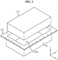
- FIG. 2 is a schematic exploded perspective view of the components of the battery module according to an embodiment of the present disclosure.
- FIG. 3 is a schematic perspective view of a plurality of secondary batteries of the battery module according to an embodiment of the present disclosure.
- the X axis direction is the right direction
- the Y axis direction is the rear direction
- the Z axis direction is the up direction.
- the battery module 200 of the present disclosure includes a cell assembly 210, a gas pipe 230 and a module housing 220.
- the cell assembly 210 may include a plurality of secondary batteries 211.
- the secondary battery 211 may be a pouch-type secondary battery.
- the cell assembly 210 may include 21 pouch-type secondary batteries 211 stacked side by side in a direction (Y axis direction) within a case.
- the positive electrode lead 211a and the negative electrode lead 211b may be formed at two ends with regard to the center of a pouch 116 of the secondary battery 211. That is, the positive electrode lead 211a may be provided at one end with regard to the center of the secondary battery 211. Additionally, the negative electrode lead 211b may be provided at the other end with regard to the center of the secondary battery 211.
- the configuration of the secondary battery is not limited to the above-described pouch-type secondary battery 211 and various types of secondary batteries 211 known at the time of filing the patent application may be employed.
- the battery module 200 may include at least one busbar (not shown) configured to electrically connect the plurality of secondary batteries 211.
- the busbar may include a conductive metal, for example, copper, aluminum and nickel.
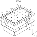
- FIG. 4 is a schematic exploded perspective view of the components of the battery module according to an embodiment of the present disclosure. Additionally, FIG. 5 is a schematic perspective view of the components of the battery module 200 according to an embodiment of the present disclosure.
- the gas pipe 230 may be configured to allow gas produced in the module housing 220 to move therein. That is, the gas pipe 230 may be in the shape of a pipe that extends in a direction in which gas moves.
- the gas pipe 230 may include a metal or plastic material.
- the module housing 220 may include a metal or plastic material.
- the module housing 220 may include a lower case 222 and an upper case 224.
- the lower case 222 may have an internal space 222a in which the at least one cell assembly 210 is received. That is, the lower case 222 may have walls W1 that form the internal space 222a that is equal to or larger than the volume of the cell assembly 210.
- the internal space 222a may have one open side.
- the upper case 224 may be configured to cover the open side of the lower case 222. That is, the upper case 224 may have a wider area than the open area of the lower case 222.
- the upper case 224 may have a plate shape extending in a horizontal direction (X axis direction and Y axis direction).
- the upper case 224 may be coupled to one side of the lower case 222.
- the horizontal direction refers to a direction parallel to the ground when the battery module 200 is placed on the ground.
- the upper case 224 may have a receiving space 224a in which at least part of the gas pipe 230 is received. That is, the receiving space 224a may be a space that is recessed in the downward direction at the central area of the upper case 224. The receiving space 224a may have a size that is large enough to accommodate at least part of the gas pipe 230.
- the upper case 224 may include a connection hole H1 to allow the gas pipe 230 and the internal space 222a of the lower case 222 to be in communication with each other. Accordingly, one end of the gas pipe 230 may be connected to the connection hole H1. The gas fed into one end of the gas pipe 230 may move in the horizontal direction along the pipe to the other end (the end, 232t) of the gas pipe 230.
- the present disclosure includes the upper case 224 configured such that the gas pipe 230 and the internal space 222a of the lower case 222 are in communication with each other, to cause flames and gas produced by fires or explosions of the internal components such as the cell assembly 210 to move through the gas pipe 230 disposed in the receiving space 224a. Accordingly, the present disclosure may cause flames to move in the gas pipe 230 while preventing flames from being immediately released out of the battery module 200. Further, the present disclosure may release gas to the outside after reducing the gas explosive power with the movement of gas along the gas pipe 230 in the event of gas explosions of the plurality of secondary batteries 211.
- the present disclosure may prevent the fire propagation to the adjacent other battery module 200 or other external components and reduce damage to the adjacent external components of the battery module 200 in the event of explosions of the plurality of secondary batteries 211.
- FIG. 6 is a schematic partial perspective view of the gas pipe of the battery module according to an embodiment of the present disclosure.
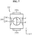
- FIG. 7 is a schematic side view of the components of the gas pipe of the battery module according to an embodiment of the present disclosure.
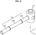
- FIG. 8 is a schematic partial perspective view of the gas pipe of the battery module according to an embodiment of the present disclosure.
- the gas pipe 230 of the present disclosure may include at least one connecting unit 232 and at least one pipe unit 234.
- the connecting unit 232 may have a pipe shape that extends in the vertical direction.
- the connecting unit 232 may have an open top 232a or bottom 232b of the vertically extending pipe, or closed top 232a and bottom 232b.
- the connecting unit 232 may be configured to be connected with the connection hole H1.
- the open bottom 232b of the connecting unit 232 may be connected to the connection hole H1 provided in the upper case 224.
- a part of the open bottom 232b of the connecting unit 232 may be inserted into the connection hole H1. Further, for example, as shown in FIG.
- the open top 232a of the connecting unit 232 may be connected with an outlet H2 of a top plate 226. Additionally, the open top 232a and the open bottom 232b of the remaining connecting unit 232 not connected with the connection hole H1 and the outlet H2 may be closed.
- the pipe unit 234 may extend in the horizontal direction.
- the end of the pipe unit 234 may be connected with the connecting unit 232 such that it is in communication with the inside of the connecting unit 232.
- the connecting unit 232 may have an open insertion hole P into which the end of the pipe unit 234 is inserted.
- the connecting unit 232 may have the insertion hole P in each of the left side, the right side, the front side and the rear side (four directions). That is, the connecting unit 232 may be connected with 4 pipe units 234 through the 4 insertion holes P.
- the present disclosure includes the at least one connecting unit 232 and the pipe unit 234, so it is easy to assemble with the length set according to the gas explosive power of the gas pipe 230. Further, it is possible to adjust the extension direction of the gas pipe 230 according to the location at which gas of the battery module 200 is released to the outside, and thus it is possible to manufacture the gas pipe 230 of various shapes (lengths) by assembling the plurality of existing connecting units 232 and the plurality of existing pipe units 234 without needing to manufacture a new type of gas pipe 230.
- the connecting unit 232 may serve as a hub for assembly with the pipe unit 234, and when the top 232a and/or the bottom 232b are closed, serve to disperse the explosive power of gas fed into the connecting unit 232 in the vertical direction, thereby reducing the explosive power.
- the connecting unit 232 may include a sealing member 240.
- the sealing member 240 may be configured to open the insertion hole P to allow the pipe unit 234 to be inserted.
- the sealing member 240 may include an elastic material.
- the elastic material may be, for example, natural rubber, synthetic rubber or silicone rubber.
- the sealing member 240 may include at least two sealing portions 241, 242 disposed in the insertion hole P.
- the sealing member 240 may include a first sealing portion 241 and a second sealing portion 242.
- the at least two sealing portions 241, 242 may be configured to spread apart to open the insertion hole P when the end of the pipe unit 234 is inserted.
- first sealing portion 241 and the second sealing portion 242 may be separated.
- Each of the first sealing portion 241 and the second sealing portion 242 may be joined to the circumference of the insertion hole P.
- the sealing member 240 may be in the shape of a circular plate. The periphery of the circular plate may be attached to the inner side of the insertion hole P of the connecting unit 232 using an adhesive (for example, a sealant).
- each of the first sealing portion 241 and the second sealing portion 242 of the sealing member 240 may have a circular shape, and a central area B at which the first sealing portion 241 and the second sealing portion 242 are in close contact with each other may be separated.
- the end of the pipe unit 234 may be inserted into the insertion hole P of the connecting unit 232 through the separated area between the first sealing portion 241 and the second sealing portion 242.
- the sealing member 240 may play a role in preventing the end of the pipe unit 234 inserted into the insertion hole P from being separated again.
- the sealing member 240 compressed by the inserted pipe unit 234 may be restored to the original state by the elastic force and press the end of the pipe unit 234. In this instance, great friction is exerted between the sealing member 240 and the pipe unit 234, thereby preventing the pipe unit 234 from being separated from the insertion hole P.
- the sealing member 240 may be configured to form a seal between the insertion hole P of the connecting unit 232 and the end of the pipe unit 234 to prevent gas leaks between the insertion hole P of the connecting unit 232 and the end of the pipe unit 234.
- the sealing member 240 may be configured to close the insertion hole P when the pipe unit 234 is not inserted into the insertion hole P. That is, the at least two sealing portions 241, 242 may be configured to come into close contact to close the insertion hole P when the pipe unit 234 is not inserted into the insertion hole P. For example, as shown in FIG. 7 , when the pipe unit 234 is not inserted into the insertion hole P, the first sealing portion 241 and the second sealing portion 242 of the sealing member 240 may cover the insertion hole P.
- the present disclosure includes the sealing member 240, which facilitates the assembly process between the pipe unit 234 and the connecting unit 232, thereby increasing the fabrication efficiency. Further, it is possible to prevent gas moving in the gas pipe 230 from leaking in the gap between the connecting unit 232 and the pipe unit 234, thereby achieving smooth gas release.
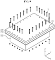
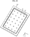
- FIG. 9 is a schematic exploded perspective view of the assembled components of the battery module according to an embodiment of the present disclosure. Additionally, FIG. 10 is a schematic bottom perspective view of the top plate of the battery module according to an embodiment of the present disclosure.
- the battery module 200 of the present disclosure may further include the top plate 226.
- the upper case 224 may have one open side of the receiving space 224a.
- the top plate 226 may be configured to cover the open side of the receiving space 224a of the upper case 224.
- the upper case 224 may include a gasket 224g between the top plate 226 and the upper case 224.
- the gasket 224g may be configured to prevent gas from leaking in the gap between the top plate 226 and the upper case 224.
- top plate 226 may be coupled with one side of the upper case 224.
- a plurality of bolts T may be inserted into each of a third fastening groove C3 formed in the top plate 226, a second fastening groove C2 formed in the upper case 224 and a first fastening groove C1 formed in the lower case 222 and fastened using nuts N.
- the top plate 226 may have the outlet H2 where gas exits.
- the outlet H2 may be open such that the inside of the module housing 220 are in communication with the outside.
- the outlet H2 may be connected to the other end of the gas pipe 230 (the end of the gas movement path, 232t in FIG. 5 ).
- the present disclosure includes the top plate 226 configured to cover one side of the receiving space 224a of the upper case 224, so the gas pipe 230 may be safely stored in the module housing 220, and when a fire or explosion occurs, produced gas is not allowed to move through the gas pipe 230, and in the event of leaks, gas may be safely received in the receiving space 224a. Ultimately, it is possible to increase the safety of the battery module 200.
- the upper case 224 may include at least one first fixing groove G1.
- the first fixing groove G1 may be recessed in the inward direction of the body at a part of the upper case 224, and one end 232b of the connecting unit 232 in the vertical direction may be inserted into the first fixing groove G1.
- the first fixing groove G1 may be configured to close one end of the connecting unit 232 in the vertical direction.
- the first fixing groove G1 may be configured to fix the location of the connecting unit 232.
- the top plate 226 may include a second fixing groove G2 into which the other end 232a of the connecting unit 232 in the vertical direction is inserted.
- the second fixing groove G2 may be recessed in the inward direction of the body at a part of the top plate 226.
- the second fixing groove G2 may be configured to close the other end 232a of the connecting unit 232 in the vertical direction.
- the second fixing groove G2 may be configured to fix the location of the connecting unit 232.
- the present disclosure includes the first fixing groove G1 formed in the upper case 224 and the second fixing groove G2 formed in the top plate 226, to fix the location of the connecting unit 232 and close at least one of one end 232b or the other end 232a of the connecting unit 232 in the vertical direction, so the connecting unit 232 may disperse (absorb) the pressure of the produced gas in the vertical direction, thereby reducing the gas explosive power.
- FIG. 11 is a schematic perspective view of the components of a battery module according to another embodiment of the present disclosure.
- the battery module 200A may include a smaller number of connecting units 232 and pipe units 234 for the same length of the gas movement path of the gas pipe 230A as the battery module 200 of FIG. 5 .
- the battery module 200A according to another embodiment of the present disclosure may include a smaller number of connecting units 232 of the gas pipes 230A when compared with the battery module 200 of FIG. 5 .
- the battery module 200 of FIG. 5 includes 24 connecting units 232, while the gas pipe 230A of FIG. 11 includes 16 connecting units 232.
- the gas pipe 230A of FIG. 11 may have approximately the same total horizontal length in which gas moves as that of FIG. 5 . It is because the gas pipe 230A of each of FIGS. 5 and 11 has similar gas release paths.
- the number of connecting units 232 of the gas pipes 230A may be decreased as in the battery module 200A of FIG. 11 . Additionally, as the number of connecting units 232 decreases, the number of pipe units 234 may decrease. The pipe unit 234 having the extended length may be connected to the connecting unit 232.
- the present disclosure may be configured to adjust the number of connecting units 232 and the number of pipe units 234 of the gas pipes 230A according to the gas explosive power of the at least one cell assembly 210, thereby reducing the number of unnecessary components, reducing the weight of the battery module and saving the manufacturing cost.
- the length of the gas pipe 230 may be adjusted according to the gas explosive power of the at least one cell assembly 210.
- the pipe unit 234 may be configured to have an adjustable length.
- the pipe unit 234 may include three pipe portions 234a, 234b, 234c.
- the pipe portion 234a disposed on the left side and the pipe portion 234c disposed on the right side may have the same diameter.
- the remaining pipe portion 234b disposed at the center may have a smaller diameter than the two pipe portions 234a, 234c.
- One part or the other part of the pipe portion 234b disposed at the center may be inserted into the left pipe portion 234a and the right pipe portion 234c respectively.
- the present disclosure may, if necessary, increase the length of the pipe unit 234 by pulling the pipe portion 234b disposed at the center from the left pipe portion 234a and the right pipe portion 234c, or may decrease the total length of the pipe unit 234 by inserting the pipe portion 234b disposed at the center into the left pipe portion 234a and the right pipe portion 234c.
- the present disclosure may adjust the length of the gas pipe 230 according to the gas explosive power of the at least one cell assembly 210, thereby appropriately changing the length and location of the gas pipe 230 according to the explosive power of the battery module 200 or the gas exhaust path.
- the gas pipe 230 since the length and location of the gas pipe 230 may be changed according to the size and shape of the battery module 200, the gas pipe 230 may be used as a standardized component. Accordingly, when there are changes of various capacities or shapes of the battery module 200, there is no need to separately manufacture the gas pipe 230, thereby reducing the manufacturing cost.
- FIG. 12 is a schematic perspective view of the components of a battery module according to still another embodiment of the present disclosure.
- the battery module 200B of FIG. 12 may have a different location of the end 232t of the gas pipe 230B connected with the outlet (not shown) of the top plate 226.
- the end 232t of the gas pipe 230B may be configured to be connected with the outlet (not shown) disposed at the rear left side of the top plate 226.
- the gas pipe 230B of FIG. 12 may be configured to have an increased gas movement path in the front-rear direction.
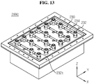
- FIG. 13 is a schematic perspective view of the components of a battery module according to yet another embodiment of the present disclosure.
- the battery module 200C of FIG. 13 may have a different location of the end 232t of the gas pipe 230C connected with the outlet (not shown) formed in the top plate 226.
- the end 232t of the gas pipe 230 may be configured to be connected with the outlet (not shown) disposed on the front right side of the top plate 226.
- the gas pipe 230C of FIG. 13 may be configured to have an increased gas movement path in the horizontal direction.
- FIG. 14 is a schematic cross-sectional view of the inside of the components of a gas pipe of a battery module according to another embodiment of the present disclosure.
- the pipe unit 234D of the gas pipe 230D of the battery module 200 may include a plurality of interruption protrusions K therein.
- the plurality of interruption protrusions K may be configured to interrupt the movement of gas in the movement space in which gas moves.
- the plurality of interruption protrusions K may extend at an angle from the inner surface of the pipe unit 234D toward a direction opposite to the gas movement direction G.
- the plurality of interruption protrusions K may be configured to reduce the gas movement rate by friction with the moving gas.
- the present disclosure includes the plurality of interruption protrusions K in the gas pipe 230D to reduce the gas movement rate, thereby effectively reducing the gas explosive power released to the outside through the gas pipe 230D. Accordingly, it is possible to effectively enhance the safety of the battery module.
- a battery pack includes at least one battery module 200.
- the battery pack may further include various types of devices (not shown) for controlling the charge/discharge of the battery module 200, for example, a Battery Management System (BMS), a current sensor and a fuse.
- BMS Battery Management System
- an electronic device (not shown) according to an embodiment of the present disclosure includes at last one battery module 200.
- the electronic device may further include a device housing (not shown) having a receiving space for receiving the battery pack and a display unit to allow a user to see the state of charge of the battery pack.
- a vehicle according to an embodiment of the present disclosure may include at least one battery pack.
- the vehicle may be a vehicle such as an electric vehicle or a hybrid electric vehicle. That is, the vehicle according to an embodiment of the present disclosure may include the battery pack according to an embodiment of the present disclosure mounted in the vehicle body.
Abstract
Description
- The present disclosure relates to a battery module, a battery pack comprising the same and a vehicle, and more particularly, to a battery module with improved safety against fires or explosions.
- The present application claims the benefit of
Korean Patent Application No. 10-2020-0061866 filed on May 22, 2020 - Recently, with the rapid increase in demand for portable electronic products such as laptop computers, video cameras and mobile phones and the extensive development of electric vehicles, accumulators for energy storage, robots and satellites, many studies are being made on high performance secondary batteries that can be repeatedly recharged.
- Currently, commercially available secondary batteries include nickel-cadmium batteries, nickel-hydrogen batteries, nickel-zinc batteries, lithium secondary batteries and the like, and among them, lithium secondary batteries have little or no memory effect, and thus they are gaining more attention than nickel-based secondary batteries for their advantages that recharging can be done whenever it is convenient, the self-discharge rate is very low and the energy density is high.
- A lithium secondary battery primarily uses a lithium-based oxide and a carbon material as a positive electrode active material and a negative electrode active material respectively. Additionally, the lithium secondary battery includes an electrode assembly including a positive electrode plate and a negative electrode plate coated with the positive electrode active material and the negative electrode active material respectively with a separator interposed between the positive electrode plate and the negative electrode plate, and a packaging or a battery case in which the electrode assembly is hermetically received together with an electrolyte solution.
- Additionally, lithium secondary batteries may be classified into can-type secondary batteries including the electrode assembly embedded in a metal can and pouch-type secondary batteries including the electrode assembly embedded in a pouch of an aluminum laminate sheet according to the shape of the packaging.
- In particular, more recently, large capacity battery modules applied to electric vehicles are increasing in demand.
- However, the large capacity battery module includes a plurality of secondary batteries, and when fires or explosions occur in the plurality of secondary batteries, the fires are likely to spread to the adjacent other battery module due to flames and high temperature gas emission. As a result, fire propagation may cause great financial damage.
- Additionally, when fires or explosions occur in the plurality of secondary batteries of the large capacity battery module, adjacent other devices are damaged or loss of human life occurs due to high temperature gas and flames released from the battery module at the time of the explosions. Accordingly, it is necessary to increase the safety against fires or gas explosions of the battery module.
- The present disclosure is designed to solve the above-described problem, and therefore the present disclosure is directed to providing a battery module with improved safety against fires or gas explosions.
- These and other objects and advantages of the present disclosure may be understood by the following description, and will be apparent from the embodiments of the present disclosure. In addition, it will be readily appreciated that the objects and advantages of the present disclosure may be realized by means and combinations thereof.
- To achieve the above-described object, a battery module according to the present disclosure includes at least one cell assembly including a plurality of secondary batteries, a gas pipe configured to allow produced gas to move therein, and a module housing including a lower case having one open side and an internal space in which the at least one cell assembly is received, and an upper case coupled to one side of the lower case to cover the one open side of the lower case and having a receiving space in which the gas pipe is received, and a connection hole to which one end of the gas pipe is connected such that the gas pipe and the internal space are in communication with each other.
- Additionally, the gas pipe may include at least one connecting unit having a pipe shape extending in a vertical direction, and configured to be connected with the connection hole, and a pipe unit which extends in a horizontal direction and has an end connected with the connecting unit.
- Furthermore, the connecting unit may include an open insertion hole into which that the end of the pipe unit is inserted, and a sealing member configured to open the insertion hole when the pipe unit is inserted into the insertion hole, and close the insertion hole when the pipe unit is not inserted into the insertion hole.
- Additionally, the sealing member may include at least two sealing portions disposed in the insertion hole, the at least two sealing portions may be configured to come into contact with each other to close the insertion hole when the pipe unit is not inserted into the insertion hole, and the at least two sealing portions may be configured to spread apart to open the insertion hole when the end of the pipe unit is inserted.
- Additionally, the upper case may have one open side of the receiving space, and the battery module may further include a top plate coupled with one side of the upper case to cover the open side of the receiving space of the upper case, and having an outlet connected with the other end of the gas pipe to release gas to outside.
- Furthermore, the upper case may include a first fixing groove recessed in an inward direction, into which one end of the connecting unit in the vertical direction is inserted, and the top plate may include a second fixing groove recessed in the inward direction, into which the other end of the connecting unit in the vertical direction is inserted.
- Additionally, the gas pipe may be configured to have an adjustable length according to gas explosive power of the at least one cell assembly.
- Additionally, the gas pipe may include a plurality of interruption protrusions configured to interrupt movement of gas in a movement space in which the gas moves.
- Further, to achieve the above-described object, a battery pack according to the present disclosure includes at least one battery module.
- Additionally, to achieve the above-described object, a vehicle according to the present disclosure includes at least one battery pack.
- According to an aspect of the present disclosure, the present disclosure includes the gas pipe and the upper case having the internal space in communication with the gas pipe, to cause flames or gas produced by fires or explosions of the internal components such as the cell assembly to move through the gas pipe disposed in the receiving space. Accordingly, the present disclosure may cause flames to move in the gas pipe while preventing flames from being directly released out of the battery module. Further, the present disclosure may release gas to the outside after reducing gas explosive power with the movement of gas along the gas pipe in the event of gas explosions of the plurality of secondary batteries.
- Further, according to an aspect of the present disclosure, the present disclosure includes the at least one connecting unit and the pipe unit, so it is easy to assemble with the length set according to the gas explosive power of the gas pipe. Further, it is possible to adjust the extension direction of the gas pipe according to the location at which gas of the battery module is released to the outside, and thus it is possible to manufacture the gas pipe of various shapes (lengths) by assembling the plurality of existing connecting units and the plurality of existing pipe units without needing to manufacture a new type of gas pipe.
- The accompanying drawings illustrate the preferred embodiments of the present disclosure, and together with the following detailed description, serve to provide a further understanding of the technical aspect of the present disclosure. However, the present disclosure should not be construed as being limited to the drawings.
-
FIG. 1 is a schematic perspective view of a battery module according to an embodiment of the present disclosure. -
FIG. 2 is a schematic exploded perspective view of components of a battery module according to an embodiment of the present disclosure. -
FIG. 3 is a schematic perspective view of a plurality of secondary batteries of a battery module according to an embodiment of the present disclosure. -
FIG. 4 is a schematic exploded perspective view of components of a battery module according to an embodiment of the present disclosure. -
FIG. 5 is a schematic perspective view of components of a battery module according to an embodiment of the present disclosure. -
FIG. 6 is a schematic partial perspective view of a gas pipe of a battery module according to an embodiment of the present disclosure. -
FIG. 7 is a schematic side view of components of a gas pipe of a battery module according to an embodiment of the present disclosure. -
FIG. 8 is a schematic partial perspective view of a gas pipe of a battery module according to an embodiment of the present disclosure. -
FIG. 9 is a schematic exploded perspective view of assembled components of a battery module according to an embodiment of the present disclosure. -
FIG. 10 is a schematic bottom perspective view of a top plate of a battery module according to an embodiment of the present disclosure. -
FIG. 11 is a schematic perspective view of components of a battery module according to another embodiment of the present disclosure. -
FIG. 12 is a schematic perspective view of components of a battery module according to still another embodiment of the present disclosure. -
FIG. 13 is a schematic perspective view of components of a battery module according to yet another embodiment of the present disclosure. -
FIG. 14 is a schematic cross-sectional view of the inside of components of a gas pipe of a battery module according to another embodiment of the present disclosure. - Hereinafter, the preferred embodiments of the present disclosure will be described in detail with reference to the accompanying drawings. Prior to the description, it should be understood that the terms or words used in the specification and the appended claims should not be construed as being limited to general and dictionary meanings, but rather interpreted based on the meanings and concepts corresponding to the technical aspects of the present disclosure on the basis of the principle that the inventor is allowed to define the terms appropriately for the best explanation.
- Therefore, the embodiments described herein and the illustrations shown in the drawings are just a most preferred embodiment of the present disclosure, but not intended to fully describe the technical aspects of the present disclosure, so it should be understood that a variety of other equivalents and modifications could have been made thereto at the time that the application was filed.
-
FIG. 1 is a schematic perspective view of a battery module according to an embodiment of the present disclosure.FIG. 2 is a schematic exploded perspective view of the components of the battery module according to an embodiment of the present disclosure. Additionally,FIG. 3 is a schematic perspective view of a plurality of secondary batteries of the battery module according to an embodiment of the present disclosure. InFIG. 1 , the X axis direction is the right direction, the Y axis direction is the rear direction, and the Z axis direction is the up direction. - Referring to
FIGS. 1 to 3 , thebattery module 200 of the present disclosure includes acell assembly 210, agas pipe 230 and amodule housing 220. - Specifically, the
cell assembly 210 may include a plurality ofsecondary batteries 211. Thesecondary battery 211 may be a pouch-type secondary battery. For example, as shown inFIG. 3 , thecell assembly 210 may include 21 pouch-typesecondary batteries 211 stacked side by side in a direction (Y axis direction) within a case. - Further, as shown in
FIG. 3 , thepositive electrode lead 211a and thenegative electrode lead 211b may be formed at two ends with regard to the center of a pouch 116 of thesecondary battery 211. That is, thepositive electrode lead 211a may be provided at one end with regard to the center of thesecondary battery 211. Additionally, thenegative electrode lead 211b may be provided at the other end with regard to the center of thesecondary battery 211. - However, in the
battery module 200 according to the present disclosure, the configuration of the secondary battery is not limited to the above-described pouch-typesecondary battery 211 and various types ofsecondary batteries 211 known at the time of filing the patent application may be employed. - Additionally, the
battery module 200 may include at least one busbar (not shown) configured to electrically connect the plurality ofsecondary batteries 211. Specifically, the busbar may include a conductive metal, for example, copper, aluminum and nickel. -
FIG. 4 is a schematic exploded perspective view of the components of the battery module according to an embodiment of the present disclosure. Additionally,FIG. 5 is a schematic perspective view of the components of thebattery module 200 according to an embodiment of the present disclosure. - Referring to
FIGS. 4 and5 together withFIGS. 2 and3 , thegas pipe 230 may be configured to allow gas produced in themodule housing 220 to move therein. That is, thegas pipe 230 may be in the shape of a pipe that extends in a direction in which gas moves. Thegas pipe 230 may include a metal or plastic material. - Additionally, the
module housing 220 may include a metal or plastic material. Themodule housing 220 may include alower case 222 and anupper case 224. Thelower case 222 may have aninternal space 222a in which the at least onecell assembly 210 is received. That is, thelower case 222 may have walls W1 that form theinternal space 222a that is equal to or larger than the volume of thecell assembly 210. Theinternal space 222a may have one open side. - Furthermore, the
upper case 224 may be configured to cover the open side of thelower case 222. That is, theupper case 224 may have a wider area than the open area of thelower case 222. For example, theupper case 224 may have a plate shape extending in a horizontal direction (X axis direction and Y axis direction). Theupper case 224 may be coupled to one side of thelower case 222. Here, the horizontal direction refers to a direction parallel to the ground when thebattery module 200 is placed on the ground. - Additionally, the
upper case 224 may have a receivingspace 224a in which at least part of thegas pipe 230 is received. That is, the receivingspace 224a may be a space that is recessed in the downward direction at the central area of theupper case 224. The receivingspace 224a may have a size that is large enough to accommodate at least part of thegas pipe 230. - Further, the
upper case 224 may include a connection hole H1 to allow thegas pipe 230 and theinternal space 222a of thelower case 222 to be in communication with each other. Accordingly, one end of thegas pipe 230 may be connected to the connection hole H1. The gas fed into one end of thegas pipe 230 may move in the horizontal direction along the pipe to the other end (the end, 232t) of thegas pipe 230. - According to this configuration of the present disclosure, the present disclosure includes the
upper case 224 configured such that thegas pipe 230 and theinternal space 222a of thelower case 222 are in communication with each other, to cause flames and gas produced by fires or explosions of the internal components such as thecell assembly 210 to move through thegas pipe 230 disposed in the receivingspace 224a. Accordingly, the present disclosure may cause flames to move in thegas pipe 230 while preventing flames from being immediately released out of thebattery module 200. Further, the present disclosure may release gas to the outside after reducing the gas explosive power with the movement of gas along thegas pipe 230 in the event of gas explosions of the plurality ofsecondary batteries 211. - In conclusion, when comparing with the case in which gas and flames produced by fires or explosions of the internal components such as the
cell assembly 210 are directly released, the present disclosure may prevent the fire propagation to the adjacentother battery module 200 or other external components and reduce damage to the adjacent external components of thebattery module 200 in the event of explosions of the plurality ofsecondary batteries 211. -
FIG. 6 is a schematic partial perspective view of the gas pipe of the battery module according to an embodiment of the present disclosure.FIG. 7 is a schematic side view of the components of the gas pipe of the battery module according to an embodiment of the present disclosure. Additionally,FIG. 8 is a schematic partial perspective view of the gas pipe of the battery module according to an embodiment of the present disclosure. - Referring to
FIGS. 5 to 8 together withFIG. 4 , thegas pipe 230 of the present disclosure may include at least one connectingunit 232 and at least onepipe unit 234. Specifically, the connectingunit 232 may have a pipe shape that extends in the vertical direction. The connectingunit 232 may have an open top 232a or bottom 232b of the vertically extending pipe, or closed top 232a and bottom 232b. The connectingunit 232 may be configured to be connected with the connection hole H1. For example, theopen bottom 232b of the connectingunit 232 may be connected to the connection hole H1 provided in theupper case 224. A part of theopen bottom 232b of the connectingunit 232 may be inserted into the connection hole H1. Further, for example, as shown inFIG. 1 , the open top 232a of the connectingunit 232 may be connected with an outlet H2 of atop plate 226. Additionally, the open top 232a and theopen bottom 232b of the remaining connectingunit 232 not connected with the connection hole H1 and the outlet H2 may be closed. - Additionally, the
pipe unit 234 may extend in the horizontal direction. The end of thepipe unit 234 may be connected with the connectingunit 232 such that it is in communication with the inside of the connectingunit 232. For example, the connectingunit 232 may have an open insertion hole P into which the end of thepipe unit 234 is inserted. - For example, as shown in
FIG. 5 , the connectingunit 232 may have the insertion hole P in each of the left side, the right side, the front side and the rear side (four directions). That is, the connectingunit 232 may be connected with 4pipe units 234 through the 4 insertion holes P. - According to this configuration of the present disclosure, the present disclosure includes the at least one connecting
unit 232 and thepipe unit 234, so it is easy to assemble with the length set according to the gas explosive power of thegas pipe 230. Further, it is possible to adjust the extension direction of thegas pipe 230 according to the location at which gas of thebattery module 200 is released to the outside, and thus it is possible to manufacture thegas pipe 230 of various shapes (lengths) by assembling the plurality of existing connectingunits 232 and the plurality of existingpipe units 234 without needing to manufacture a new type ofgas pipe 230. - Further, the connecting
unit 232 may serve as a hub for assembly with thepipe unit 234, and when the top 232a and/or the bottom 232b are closed, serve to disperse the explosive power of gas fed into the connectingunit 232 in the vertical direction, thereby reducing the explosive power. - Additionally, the connecting
unit 232 may include a sealingmember 240. When thepipe unit 234 is inserted into the insertion hole P, the sealingmember 240 may be configured to open the insertion hole P to allow thepipe unit 234 to be inserted. For example, the sealingmember 240 may include an elastic material. The elastic material may be, for example, natural rubber, synthetic rubber or silicone rubber. - Additionally, the sealing
member 240 may include at least two sealingportions member 240 may include afirst sealing portion 241 and asecond sealing portion 242. The at least two sealingportions pipe unit 234 is inserted. - For example, at least part of the
first sealing portion 241 and thesecond sealing portion 242 may be separated. Each of thefirst sealing portion 241 and thesecond sealing portion 242 may be joined to the circumference of the insertion hole P. For example, the sealingmember 240 may be in the shape of a circular plate. The periphery of the circular plate may be attached to the inner side of the insertion hole P of the connectingunit 232 using an adhesive (for example, a sealant). - Further, each of the
first sealing portion 241 and thesecond sealing portion 242 of the sealingmember 240 may have a circular shape, and a central area B at which thefirst sealing portion 241 and thesecond sealing portion 242 are in close contact with each other may be separated. For example, as shown inFIGS. 6 and7 , the end of thepipe unit 234 may be inserted into the insertion hole P of the connectingunit 232 through the separated area between thefirst sealing portion 241 and thesecond sealing portion 242. The sealingmember 240 may play a role in preventing the end of thepipe unit 234 inserted into the insertion hole P from being separated again. - Additionally, the sealing
member 240 compressed by the insertedpipe unit 234 may be restored to the original state by the elastic force and press the end of thepipe unit 234. In this instance, great friction is exerted between the sealingmember 240 and thepipe unit 234, thereby preventing thepipe unit 234 from being separated from the insertion hole P. - Furthermore, the sealing
member 240 may be configured to form a seal between the insertion hole P of the connectingunit 232 and the end of thepipe unit 234 to prevent gas leaks between the insertion hole P of the connectingunit 232 and the end of thepipe unit 234. - Additionally, the sealing
member 240 may be configured to close the insertion hole P when thepipe unit 234 is not inserted into the insertion hole P. That is, the at least two sealingportions pipe unit 234 is not inserted into the insertion hole P. For example, as shown inFIG. 7 , when thepipe unit 234 is not inserted into the insertion hole P, thefirst sealing portion 241 and thesecond sealing portion 242 of the sealingmember 240 may cover the insertion hole P. - According to this configuration of the present disclosure, the present disclosure includes the sealing
member 240, which facilitates the assembly process between thepipe unit 234 and the connectingunit 232, thereby increasing the fabrication efficiency. Further, it is possible to prevent gas moving in thegas pipe 230 from leaking in the gap between the connectingunit 232 and thepipe unit 234, thereby achieving smooth gas release. -
FIG. 9 is a schematic exploded perspective view of the assembled components of the battery module according to an embodiment of the present disclosure. Additionally,FIG. 10 is a schematic bottom perspective view of the top plate of the battery module according to an embodiment of the present disclosure. - Meanwhile, referring to
FIGS. 9 and10 together withFIG. 4 , thebattery module 200 of the present disclosure may further include thetop plate 226. Theupper case 224 may have one open side of the receivingspace 224a. Thetop plate 226 may be configured to cover the open side of the receivingspace 224a of theupper case 224. Theupper case 224 may include agasket 224g between thetop plate 226 and theupper case 224. Thegasket 224g may be configured to prevent gas from leaking in the gap between thetop plate 226 and theupper case 224. - Additionally, the
top plate 226 may be coupled with one side of theupper case 224. For example, as shown inFIGS. 5 and9 , a plurality of bolts T may be inserted into each of a third fastening groove C3 formed in thetop plate 226, a second fastening groove C2 formed in theupper case 224 and a first fastening groove C1 formed in thelower case 222 and fastened using nuts N. - Further, the
top plate 226 may have the outlet H2 where gas exits. The outlet H2 may be open such that the inside of themodule housing 220 are in communication with the outside. The outlet H2 may be connected to the other end of the gas pipe 230 (the end of the gas movement path, 232t inFIG. 5 ). - According to this configuration of the present disclosure, the present disclosure includes the
top plate 226 configured to cover one side of the receivingspace 224a of theupper case 224, so thegas pipe 230 may be safely stored in themodule housing 220, and when a fire or explosion occurs, produced gas is not allowed to move through thegas pipe 230, and in the event of leaks, gas may be safely received in the receivingspace 224a. Ultimately, it is possible to increase the safety of thebattery module 200. - Additionally, referring back to
FIG. 4 , theupper case 224 may include at least one first fixing groove G1. The first fixing groove G1 may be recessed in the inward direction of the body at a part of theupper case 224, and oneend 232b of the connectingunit 232 in the vertical direction may be inserted into the first fixing groove G1. The first fixing groove G1 may be configured to close one end of the connectingunit 232 in the vertical direction. The first fixing groove G1 may be configured to fix the location of the connectingunit 232. - Further, referring back to
FIG. 10 , thetop plate 226 may include a second fixing groove G2 into which theother end 232a of the connectingunit 232 in the vertical direction is inserted. The second fixing groove G2 may be recessed in the inward direction of the body at a part of thetop plate 226. The second fixing groove G2 may be configured to close theother end 232a of the connectingunit 232 in the vertical direction. The second fixing groove G2 may be configured to fix the location of the connectingunit 232. - According to this configuration of the present disclosure, the present disclosure includes the first fixing groove G1 formed in the
upper case 224 and the second fixing groove G2 formed in thetop plate 226, to fix the location of the connectingunit 232 and close at least one of oneend 232b or theother end 232a of the connectingunit 232 in the vertical direction, so the connectingunit 232 may disperse (absorb) the pressure of the produced gas in the vertical direction, thereby reducing the gas explosive power. -
FIG. 11 is a schematic perspective view of the components of a battery module according to another embodiment of the present disclosure. - Referring to
FIG. 11 together withFIG. 5 , thebattery module 200A according to another embodiment of the present disclosure may include a smaller number of connectingunits 232 andpipe units 234 for the same length of the gas movement path of thegas pipe 230A as thebattery module 200 ofFIG. 5 . For example, thebattery module 200A according to another embodiment of the present disclosure may include a smaller number of connectingunits 232 of thegas pipes 230A when compared with thebattery module 200 ofFIG. 5 . - For example, the
battery module 200 ofFIG. 5 includes 24 connectingunits 232, while thegas pipe 230A ofFIG. 11 includes 16 connectingunits 232. However, thegas pipe 230A ofFIG. 11 may have approximately the same total horizontal length in which gas moves as that ofFIG. 5 . It is because thegas pipe 230A of each ofFIGS. 5 and11 has similar gas release paths. - Compared with the
battery module 200 ofFIG. 5 , when the battery capacity or the gas explosive power is lower, the number of connectingunits 232 of thegas pipes 230A may be decreased as in thebattery module 200A ofFIG. 11 . Additionally, as the number of connectingunits 232 decreases, the number ofpipe units 234 may decrease. Thepipe unit 234 having the extended length may be connected to the connectingunit 232. - According to this configuration of the present disclosure, the present disclosure may be configured to adjust the number of connecting
units 232 and the number ofpipe units 234 of thegas pipes 230A according to the gas explosive power of the at least onecell assembly 210, thereby reducing the number of unnecessary components, reducing the weight of the battery module and saving the manufacturing cost. - Additionally, referring back to
FIGS. 6 and8 , the length of thegas pipe 230 may be adjusted according to the gas explosive power of the at least onecell assembly 210. Specifically, thepipe unit 234 may be configured to have an adjustable length. - For example, referring to
FIG. 8 , thepipe unit 234 may include threepipe portions FIG. 8 , thepipe portion 234a disposed on the left side and thepipe portion 234c disposed on the right side may have the same diameter. The remainingpipe portion 234b disposed at the center may have a smaller diameter than the twopipe portions pipe portion 234b disposed at the center may be inserted into theleft pipe portion 234a and theright pipe portion 234c respectively. - Accordingly, the present disclosure may, if necessary, increase the length of the
pipe unit 234 by pulling thepipe portion 234b disposed at the center from theleft pipe portion 234a and theright pipe portion 234c, or may decrease the total length of thepipe unit 234 by inserting thepipe portion 234b disposed at the center into theleft pipe portion 234a and theright pipe portion 234c. - According to this configuration of the present disclosure, the present disclosure may adjust the length of the
gas pipe 230 according to the gas explosive power of the at least onecell assembly 210, thereby appropriately changing the length and location of thegas pipe 230 according to the explosive power of thebattery module 200 or the gas exhaust path. - That is, since the length and location of the
gas pipe 230 may be changed according to the size and shape of thebattery module 200, thegas pipe 230 may be used as a standardized component. Accordingly, when there are changes of various capacities or shapes of thebattery module 200, there is no need to separately manufacture thegas pipe 230, thereby reducing the manufacturing cost. -
FIG. 12 is a schematic perspective view of the components of a battery module according to still another embodiment of the present disclosure. - Referring to
FIG. 12 together withFIG. 1 , when compared with thegas pipe 230A of thebattery module 200A ofFIG. 11 , thebattery module 200B ofFIG. 12 may have a different location of theend 232t of thegas pipe 230B connected with the outlet (not shown) of thetop plate 226. For example, as shown inFIG. 12 , theend 232t of thegas pipe 230B may be configured to be connected with the outlet (not shown) disposed at the rear left side of thetop plate 226. Additionally, thegas pipe 230B ofFIG. 12 may be configured to have an increased gas movement path in the front-rear direction. -
FIG. 13 is a schematic perspective view of the components of a battery module according to yet another embodiment of the present disclosure. - Referring to
FIG. 13 together withFIG. 1 , when compared with thegas pipe 230A of thebattery module 200A ofFIG. 11 , the battery module 200C ofFIG. 13 may have a different location of theend 232t of the gas pipe 230C connected with the outlet (not shown) formed in thetop plate 226. For example, as shown inFIG. 13 , theend 232t of thegas pipe 230 may be configured to be connected with the outlet (not shown) disposed on the front right side of thetop plate 226. Additionally, the gas pipe 230C ofFIG. 13 may be configured to have an increased gas movement path in the horizontal direction. -
FIG. 14 is a schematic cross-sectional view of the inside of the components of a gas pipe of a battery module according to another embodiment of the present disclosure. - Referring to
FIG. 14 , the pipe unit 234D of the gas pipe 230D of thebattery module 200 according to another embodiment of the present disclosure may include a plurality of interruption protrusions K therein. The plurality of interruption protrusions K may be configured to interrupt the movement of gas in the movement space in which gas moves. The plurality of interruption protrusions K may extend at an angle from the inner surface of the pipe unit 234D toward a direction opposite to the gas movement direction G. The plurality of interruption protrusions K may be configured to reduce the gas movement rate by friction with the moving gas. - According to this configuration of the present disclosure, the present disclosure includes the plurality of interruption protrusions K in the gas pipe 230D to reduce the gas movement rate, thereby effectively reducing the gas explosive power released to the outside through the gas pipe 230D. Accordingly, it is possible to effectively enhance the safety of the battery module.
- Meanwhile, a battery pack according to an embodiment of the present disclosure includes at least one
battery module 200. - Additionally, the battery pack may further include various types of devices (not shown) for controlling the charge/discharge of the
battery module 200, for example, a Battery Management System (BMS), a current sensor and a fuse. - Meanwhile, an electronic device (not shown) according to an embodiment of the present disclosure includes at last one
battery module 200. The electronic device may further include a device housing (not shown) having a receiving space for receiving the battery pack and a display unit to allow a user to see the state of charge of the battery pack. - Additionally, a vehicle according to an embodiment of the present disclosure may include at least one battery pack. The vehicle may be a vehicle such as an electric vehicle or a hybrid electric vehicle. That is, the vehicle according to an embodiment of the present disclosure may include the battery pack according to an embodiment of the present disclosure mounted in the vehicle body.
- Meanwhile, the terms indicating directions as used herein such as upper, lower, left, right, front and rear are used for convenience of description only, and it is obvious to those skilled in the art that the term may change depending on the position of the stated element or an observer.
- While the present disclosure has been hereinabove described with regard to a limited number of embodiments and drawings, the present disclosure is not limited thereto and it is obvious to those skilled in the art that various modifications and changes may be made thereto within the technical aspects of the present disclosure and the equivalent scope of the appended claims.
[Description of Reference Numerals] 200: Battery module 210: Cell assembly 211: Secondary battery 220: Module housing 222: Lower case 224: Upper case 226: Top plate 222a, 224a: Internal space, Receiving space HI, H2: Connection hole, Outlet 230: Gas pipe 232: Connecting unit 234: Pipe unit P: Insertion hole 240: Sealing member 241, 242: First sealing portion, Second sealing portion G1, G2: First fixing groove, Second fixing groove K: Interruption protrusion
Claims (10)
- A battery module, comprising:at least one cell assembly including a plurality of secondary batteries;a gas pipe configured to allow produced gas to move therein; anda module housing including a lower case having one open side and an internal space in which the at least one cell assembly is received, and an upper case coupled to one side of the lower case to cover the open side of the lower case and having a receiving space in which the gas pipe is received, and a connection hole to which one end of the gas pipe is connected such that the gas pipe and the internal space are in communication with each other.
- The battery module according to claim 1, wherein the gas pipe includes:at least one connecting unit having a pipe shape extending in a vertical direction, and configured to be connected with the connection hole; anda pipe unit which extends in a horizontal direction and has an end connected with the connecting unit.
- The battery module according to claim 2, wherein the connecting unit includes:an open insertion hole into which that the end of the pipe unit is inserted, anda sealing member configured to open the insertion hole when the pipe unit is inserted into the insertion hole, and close the insertion hole when the pipe unit is not inserted into the insertion hole.
- The battery module according to claim 3, wherein the sealing member includes at least two sealing portions disposed in the insertion hole,the at least two sealing portions are configured to come into contact with each other to close the insertion hole when the pipe unit is not inserted into the insertion hole, andthe at least two sealing portions are configured to spread apart to open the insertion hole when the end of the pipe unit is inserted.
- The battery module according to claim 2, wherein the upper case has one open side of the receiving space, and
the battery module further comprises:
a top plate coupled with one side of the upper case to cover the open side of the receiving space of the upper case, and having an outlet connected with the other end of the gas pipe to release gas to outside. - The battery module according to claim 5, wherein the upper case includes a first fixing groove recessed in an inward direction, into which one end of the connecting unit in the vertical direction is inserted, and
the top plate includes a second fixing groove recessed in the inward direction, into which the other end of the connecting unit in the vertical direction is inserted. - The battery module according to claim 2, wherein the gas pipe is configured to have an adjustable length according to gas explosive power of the at least one cell assembly.
- The battery module according to claim 7, wherein the gas pipe includes a plurality of interruption protrusions configured to interrupt movement of gas in a movement space in which the gas moves.
- A battery pack comprising at least one battery module according to any one of claims 1 to 8.
- A vehicle comprising at least one battery pack according to claim 9.
Applications Claiming Priority (2)
| Application Number | Priority Date | Filing Date | Title |
|---|---|---|---|
| KR1020200061866A KR20210144463A (en) | 2020-05-22 | 2020-05-22 | Battery Module and Battery Pack Comprising the Same and Vehicle |
| PCT/KR2021/005769 WO2021235751A1 (en) | 2020-05-22 | 2021-05-07 | Battery module, battery pack comprising same, and vehicle |
Publications (2)
| Publication Number | Publication Date |
|---|---|
| EP4024593A1 true EP4024593A1 (en) | 2022-07-06 |
| EP4024593A4 EP4024593A4 (en) | 2023-07-19 |
Family
ID=78708779
Family Applications (1)
| Application Number | Title | Priority Date | Filing Date |
|---|---|---|---|
| EP21807642.0A Pending EP4024593A4 (en) | 2020-05-22 | 2021-05-07 | Battery module, battery pack comprising same, and vehicle |
Country Status (6)
| Country | Link |
|---|---|
| US (1) | US20240106037A1 (en) |
| EP (1) | EP4024593A4 (en) |
| JP (1) | JP7255021B2 (en) |
| KR (1) | KR20210144463A (en) |
| CN (1) | CN114342164A (en) |
| WO (1) | WO2021235751A1 (en) |
Cited By (2)
| Publication number | Priority date | Publication date | Assignee | Title |
|---|---|---|---|---|
| EP4080659A4 (en) * | 2020-08-26 | 2023-08-16 | LG Energy Solution, Ltd. | Battery module, and battery pack and automobile including same |
| EP4184695A4 (en) * | 2021-01-08 | 2024-03-27 | Lg Energy Solution Ltd | Battery module, and battery pack and vehicle comprising same |
Families Citing this family (1)
| Publication number | Priority date | Publication date | Assignee | Title |
|---|---|---|---|---|
| WO2023128576A1 (en) * | 2021-12-27 | 2023-07-06 | 주식회사 엘지에너지솔루션 | Battery pack, and ess and vehicle comprising same |
Family Cites Families (14)
| Publication number | Priority date | Publication date | Assignee | Title |
|---|---|---|---|---|
| JP2967904B2 (en) * | 1994-03-01 | 1999-10-25 | 本田技研工業株式会社 | Gas exhaust device for battery for electric vehicle |
| JP4370027B2 (en) * | 1999-10-08 | 2009-11-25 | パナソニック株式会社 | Assembled battery |
| KR100353948B1 (en) * | 2000-12-01 | 2002-09-28 | 기아자동차주식회사 | Fuel evaporation gas transpiration structure |
| JP2002216731A (en) | 2001-01-23 | 2002-08-02 | Toyota Motor Corp | Gas discharge structure of battery |
| JP2005339932A (en) | 2004-05-26 | 2005-12-08 | Toyota Motor Corp | Battery pack |
| JP5332397B2 (en) | 2008-08-21 | 2013-11-06 | 株式会社Gsユアサ | Battery system |
| JP2010108788A (en) | 2008-10-30 | 2010-05-13 | Sanyo Electric Co Ltd | Battery system |
| JP5466906B2 (en) * | 2009-09-18 | 2014-04-09 | パナソニック株式会社 | Battery module |
| CN201608218U (en) * | 2010-01-11 | 2010-10-13 | 深圳日海通讯技术股份有限公司 | Buried battery cupboard |
| JP5636330B2 (en) | 2011-04-12 | 2014-12-03 | 日立オートモティブシステムズ株式会社 | Lithium ion secondary battery |
| JP6056499B2 (en) * | 2013-01-21 | 2017-01-11 | 株式会社豊田自動織機 | Battery case |
| KR102061872B1 (en) * | 2016-01-28 | 2020-01-02 | 주식회사 엘지화학 | Case for Secondary Battery Pack and Secondary Battery Pack including the same |
| US20190173074A1 (en) * | 2017-12-04 | 2019-06-06 | Kabushiki Kaisha Toshiba | Battery |
| KR20200061866A (en) | 2018-11-26 | 2020-06-03 | 주식회사 휴비스 | Cationic-dyeable polyester resin and cationic-dyeable polyester fiber with improved dyeing property using the same |
-
2020
- 2020-05-22 KR KR1020200061866A patent/KR20210144463A/en unknown
-
2021
- 2021-05-07 US US17/767,669 patent/US20240106037A1/en active Pending
- 2021-05-07 EP EP21807642.0A patent/EP4024593A4/en active Pending
- 2021-05-07 CN CN202180004998.0A patent/CN114342164A/en active Pending
- 2021-05-07 WO PCT/KR2021/005769 patent/WO2021235751A1/en active Application Filing
- 2021-05-07 JP JP2022512830A patent/JP7255021B2/en active Active
Cited By (2)
| Publication number | Priority date | Publication date | Assignee | Title |
|---|---|---|---|---|
| EP4080659A4 (en) * | 2020-08-26 | 2023-08-16 | LG Energy Solution, Ltd. | Battery module, and battery pack and automobile including same |
| EP4184695A4 (en) * | 2021-01-08 | 2024-03-27 | Lg Energy Solution Ltd | Battery module, and battery pack and vehicle comprising same |
Also Published As
| Publication number | Publication date |
|---|---|
| JP7255021B2 (en) | 2023-04-10 |
| KR20210144463A (en) | 2021-11-30 |
| EP4024593A4 (en) | 2023-07-19 |
| CN114342164A (en) | 2022-04-12 |
| JP2022546691A (en) | 2022-11-07 |
| WO2021235751A1 (en) | 2021-11-25 |
| US20240106037A1 (en) | 2024-03-28 |
Similar Documents
| Publication | Publication Date | Title |
|---|---|---|
| EP4024593A1 (en) | Battery module, battery pack comprising same, and vehicle | |
| KR101996250B1 (en) | Secondary battery and secondary batter pack having the same | |
| WO2024016451A1 (en) | Top cover assembly, battery cell, battery and electric device | |
| KR20160054269A (en) | Battery module and battery pack including the same | |
| KR101370144B1 (en) | Square lithium type cell | |
| JP7417766B2 (en) | Battery module with improved fire prevention performance | |
| KR20170110821A (en) | Battery Cell Comprising Cylindrical Can Having Screw-typed Fastening Portion | |
| JP4117435B2 (en) | Battery module | |
| US20240006707A1 (en) | Secondary battery and manufacturing method of the same | |
| EP4203163A1 (en) | Battery module, battery pack comprising same, and automobile | |
| EP4037070A1 (en) | Battery pack, electronic device comprising same, and vehicle | |
| EP4175041A1 (en) | Battery module, battery pack, and vehicle | |
| US20230051278A1 (en) | Battery module, and battery pack and automobile including same | |
| KR101514426B1 (en) | Connector, battery pack having the same and assembling method thereof | |
| KR20220077517A (en) | Battery pack having gas discharging unit | |
| EP4207461A1 (en) | Battery pack and automobile including same | |
| KR20200055336A (en) | Battery pack | |
| US20240154238A1 (en) | Battery pack and vehicle comprising the same | |
| EP4044341A1 (en) | Battery module and battery pack including same | |
| EP4064430A1 (en) | Battery module, battery pack comprising same, and vehicle | |
| EP4050715A1 (en) | Battery pack, electronic device, and vehicle | |
| US20240097209A1 (en) | Battery cell, battery, electric apparatus, and manufacturing method and device of battery cell | |
| US20230327279A1 (en) | Flame arrester and battery pack including the same | |
| KR20240045544A (en) | Battery pack and vehicle including the same | |
| KR20220069392A (en) | Secondary battery and battery module including the same |
Legal Events
| Date | Code | Title | Description |
|---|---|---|---|
| STAA | Information on the status of an ep patent application or granted ep patent |
Free format text: STATUS: THE INTERNATIONAL PUBLICATION HAS BEEN MADE |
|
| PUAI | Public reference made under article 153(3) epc to a published international application that has entered the european phase |
Free format text: ORIGINAL CODE: 0009012 |
|
| STAA | Information on the status of an ep patent application or granted ep patent |
Free format text: STATUS: REQUEST FOR EXAMINATION WAS MADE |
|
| 17P | Request for examination filed |
Effective date: 20220330 |
|
| AK | Designated contracting states |
Kind code of ref document: A1 Designated state(s): AL AT BE BG CH CY CZ DE DK EE ES FI FR GB GR HR HU IE IS IT LI LT LU LV MC MK MT NL NO PL PT RO RS SE SI SK SM TR |
|
| A4 | Supplementary search report drawn up and despatched |
Effective date: 20230619 |
|
| RIC1 | Information provided on ipc code assigned before grant |
Ipc: H01M 50/358 20210101ALI20230613BHEP Ipc: H01M 50/271 20210101ALI20230613BHEP Ipc: H01M 50/211 20210101ALI20230613BHEP Ipc: H01M 50/20 20210101ALI20230613BHEP Ipc: H01M 50/35 20210101ALI20230613BHEP Ipc: H01M 50/30 20210101AFI20230613BHEP |
|
| DAV | Request for validation of the european patent (deleted) | ||
| DAX | Request for extension of the european patent (deleted) |