EP4024581B1 - Battery rack and energy storage system comprising the same - Google Patents
Battery rack and energy storage system comprising the same Download PDFInfo
- Publication number
- EP4024581B1 EP4024581B1 EP21764281.8A EP21764281A EP4024581B1 EP 4024581 B1 EP4024581 B1 EP 4024581B1 EP 21764281 A EP21764281 A EP 21764281A EP 4024581 B1 EP4024581 B1 EP 4024581B1
- Authority
- EP
- European Patent Office
- Prior art keywords
- battery
- rack
- battery pack
- fire extinguishing
- extinguishing liquid
- Prior art date
- Legal status (The legal status is an assumption and is not a legal conclusion. Google has not performed a legal analysis and makes no representation as to the accuracy of the status listed.)
- Active
Links
Images


Classifications
-
- H—ELECTRICITY
- H01—ELECTRIC ELEMENTS
- H01M—PROCESSES OR MEANS, e.g. BATTERIES, FOR THE DIRECT CONVERSION OF CHEMICAL ENERGY INTO ELECTRICAL ENERGY
- H01M50/00—Constructional details or processes of manufacture of the non-active parts of electrochemical cells other than fuel cells, e.g. hybrid cells
- H01M50/20—Mountings; Secondary casings or frames; Racks, modules or packs; Suspension devices; Shock absorbers; Transport or carrying devices; Holders
-
- A—HUMAN NECESSITIES
- A62—LIFE-SAVING; FIRE-FIGHTING
- A62C—FIRE-FIGHTING
- A62C3/00—Fire prevention, containment or extinguishing specially adapted for particular objects or places
- A62C3/16—Fire prevention, containment or extinguishing specially adapted for particular objects or places in electrical installations, e.g. cableways
-
- A—HUMAN NECESSITIES
- A62—LIFE-SAVING; FIRE-FIGHTING
- A62C—FIRE-FIGHTING
- A62C35/00—Permanently-installed equipment
- A62C35/02—Permanently-installed equipment with containers for delivering the extinguishing substance
- A62C35/11—Permanently-installed equipment with containers for delivering the extinguishing substance controlled by a signal from the danger zone
-
- H—ELECTRICITY
- H01—ELECTRIC ELEMENTS
- H01M—PROCESSES OR MEANS, e.g. BATTERIES, FOR THE DIRECT CONVERSION OF CHEMICAL ENERGY INTO ELECTRICAL ENERGY
- H01M10/00—Secondary cells; Manufacture thereof
- H01M10/60—Heating or cooling; Temperature control
- H01M10/61—Types of temperature control
- H01M10/613—Cooling or keeping cold
-
- H—ELECTRICITY
- H01—ELECTRIC ELEMENTS
- H01M—PROCESSES OR MEANS, e.g. BATTERIES, FOR THE DIRECT CONVERSION OF CHEMICAL ENERGY INTO ELECTRICAL ENERGY
- H01M10/00—Secondary cells; Manufacture thereof
- H01M10/60—Heating or cooling; Temperature control
- H01M10/62—Heating or cooling; Temperature control specially adapted for specific applications
- H01M10/627—Stationary installations, e.g. power plant buffering or backup power supplies
-
- H—ELECTRICITY
- H01—ELECTRIC ELEMENTS
- H01M—PROCESSES OR MEANS, e.g. BATTERIES, FOR THE DIRECT CONVERSION OF CHEMICAL ENERGY INTO ELECTRICAL ENERGY
- H01M10/00—Secondary cells; Manufacture thereof
- H01M10/60—Heating or cooling; Temperature control
- H01M10/65—Means for temperature control structurally associated with the cells
- H01M10/656—Means for temperature control structurally associated with the cells characterised by the type of heat-exchange fluid
- H01M10/6567—Liquids
-
- H—ELECTRICITY
- H01—ELECTRIC ELEMENTS
- H01M—PROCESSES OR MEANS, e.g. BATTERIES, FOR THE DIRECT CONVERSION OF CHEMICAL ENERGY INTO ELECTRICAL ENERGY
- H01M50/00—Constructional details or processes of manufacture of the non-active parts of electrochemical cells other than fuel cells, e.g. hybrid cells
- H01M50/20—Mountings; Secondary casings or frames; Racks, modules or packs; Suspension devices; Shock absorbers; Transport or carrying devices; Holders
- H01M50/202—Casings or frames around the primary casing of a single cell or a single battery
-
- H—ELECTRICITY
- H01—ELECTRIC ELEMENTS
- H01M—PROCESSES OR MEANS, e.g. BATTERIES, FOR THE DIRECT CONVERSION OF CHEMICAL ENERGY INTO ELECTRICAL ENERGY
- H01M50/00—Constructional details or processes of manufacture of the non-active parts of electrochemical cells other than fuel cells, e.g. hybrid cells
- H01M50/20—Mountings; Secondary casings or frames; Racks, modules or packs; Suspension devices; Shock absorbers; Transport or carrying devices; Holders
- H01M50/204—Racks, modules or packs for multiple batteries or multiple cells
- H01M50/207—Racks, modules or packs for multiple batteries or multiple cells characterised by their shape
- H01M50/209—Racks, modules or packs for multiple batteries or multiple cells characterised by their shape adapted for prismatic or rectangular cells
-
- H—ELECTRICITY
- H01—ELECTRIC ELEMENTS
- H01M—PROCESSES OR MEANS, e.g. BATTERIES, FOR THE DIRECT CONVERSION OF CHEMICAL ENERGY INTO ELECTRICAL ENERGY
- H01M50/00—Constructional details or processes of manufacture of the non-active parts of electrochemical cells other than fuel cells, e.g. hybrid cells
- H01M50/20—Mountings; Secondary casings or frames; Racks, modules or packs; Suspension devices; Shock absorbers; Transport or carrying devices; Holders
- H01M50/204—Racks, modules or packs for multiple batteries or multiple cells
- H01M50/207—Racks, modules or packs for multiple batteries or multiple cells characterised by their shape
- H01M50/211—Racks, modules or packs for multiple batteries or multiple cells characterised by their shape adapted for pouch cells
-
- H—ELECTRICITY
- H01—ELECTRIC ELEMENTS
- H01M—PROCESSES OR MEANS, e.g. BATTERIES, FOR THE DIRECT CONVERSION OF CHEMICAL ENERGY INTO ELECTRICAL ENERGY
- H01M50/00—Constructional details or processes of manufacture of the non-active parts of electrochemical cells other than fuel cells, e.g. hybrid cells
- H01M50/20—Mountings; Secondary casings or frames; Racks, modules or packs; Suspension devices; Shock absorbers; Transport or carrying devices; Holders
- H01M50/233—Mountings; Secondary casings or frames; Racks, modules or packs; Suspension devices; Shock absorbers; Transport or carrying devices; Holders characterised by physical properties of casings or racks, e.g. dimensions
- H01M50/24—Mountings; Secondary casings or frames; Racks, modules or packs; Suspension devices; Shock absorbers; Transport or carrying devices; Holders characterised by physical properties of casings or racks, e.g. dimensions adapted for protecting batteries from their environment, e.g. from corrosion
-
- H—ELECTRICITY
- H01—ELECTRIC ELEMENTS
- H01M—PROCESSES OR MEANS, e.g. BATTERIES, FOR THE DIRECT CONVERSION OF CHEMICAL ENERGY INTO ELECTRICAL ENERGY
- H01M50/00—Constructional details or processes of manufacture of the non-active parts of electrochemical cells other than fuel cells, e.g. hybrid cells
- H01M50/20—Mountings; Secondary casings or frames; Racks, modules or packs; Suspension devices; Shock absorbers; Transport or carrying devices; Holders
- H01M50/251—Mountings; Secondary casings or frames; Racks, modules or packs; Suspension devices; Shock absorbers; Transport or carrying devices; Holders specially adapted for stationary devices, e.g. power plant buffering or backup power supplies
-
- H—ELECTRICITY
- H01—ELECTRIC ELEMENTS
- H01M—PROCESSES OR MEANS, e.g. BATTERIES, FOR THE DIRECT CONVERSION OF CHEMICAL ENERGY INTO ELECTRICAL ENERGY
- H01M50/00—Constructional details or processes of manufacture of the non-active parts of electrochemical cells other than fuel cells, e.g. hybrid cells
- H01M50/60—Arrangements or processes for filling or topping-up with liquids; Arrangements or processes for draining liquids from casings
- H01M50/668—Means for preventing spilling of liquid or electrolyte, e.g. when the battery is tilted or turned over
-
- H—ELECTRICITY
- H01—ELECTRIC ELEMENTS
- H01M—PROCESSES OR MEANS, e.g. BATTERIES, FOR THE DIRECT CONVERSION OF CHEMICAL ENERGY INTO ELECTRICAL ENERGY
- H01M50/00—Constructional details or processes of manufacture of the non-active parts of electrochemical cells other than fuel cells, e.g. hybrid cells
- H01M50/60—Arrangements or processes for filling or topping-up with liquids; Arrangements or processes for draining liquids from casings
- H01M50/691—Arrangements or processes for draining liquids from casings; Cleaning battery or cell casings
-
- H—ELECTRICITY
- H01—ELECTRIC ELEMENTS
- H01M—PROCESSES OR MEANS, e.g. BATTERIES, FOR THE DIRECT CONVERSION OF CHEMICAL ENERGY INTO ELECTRICAL ENERGY
- H01M2200/00—Safety devices for primary or secondary batteries
-
- H—ELECTRICITY
- H01—ELECTRIC ELEMENTS
- H01M—PROCESSES OR MEANS, e.g. BATTERIES, FOR THE DIRECT CONVERSION OF CHEMICAL ENERGY INTO ELECTRICAL ENERGY
- H01M2220/00—Batteries for particular applications
- H01M2220/10—Batteries in stationary systems, e.g. emergency power source in plant
-
- H—ELECTRICITY
- H01—ELECTRIC ELEMENTS
- H01M—PROCESSES OR MEANS, e.g. BATTERIES, FOR THE DIRECT CONVERSION OF CHEMICAL ENERGY INTO ELECTRICAL ENERGY
- H01M2220/00—Batteries for particular applications
- H01M2220/20—Batteries in motive systems, e.g. vehicle, ship, plane
-
- H—ELECTRICITY
- H01—ELECTRIC ELEMENTS
- H01M—PROCESSES OR MEANS, e.g. BATTERIES, FOR THE DIRECT CONVERSION OF CHEMICAL ENERGY INTO ELECTRICAL ENERGY
- H01M50/00—Constructional details or processes of manufacture of the non-active parts of electrochemical cells other than fuel cells, e.g. hybrid cells
- H01M50/20—Mountings; Secondary casings or frames; Racks, modules or packs; Suspension devices; Shock absorbers; Transport or carrying devices; Holders
- H01M50/249—Mountings; Secondary casings or frames; Racks, modules or packs; Suspension devices; Shock absorbers; Transport or carrying devices; Holders specially adapted for aircraft or vehicles, e.g. cars or trains
-
- Y—GENERAL TAGGING OF NEW TECHNOLOGICAL DEVELOPMENTS; GENERAL TAGGING OF CROSS-SECTIONAL TECHNOLOGIES SPANNING OVER SEVERAL SECTIONS OF THE IPC; TECHNICAL SUBJECTS COVERED BY FORMER USPC CROSS-REFERENCE ART COLLECTIONS [XRACs] AND DIGESTS
- Y02—TECHNOLOGIES OR APPLICATIONS FOR MITIGATION OR ADAPTATION AGAINST CLIMATE CHANGE
- Y02E—REDUCTION OF GREENHOUSE GAS [GHG] EMISSIONS, RELATED TO ENERGY GENERATION, TRANSMISSION OR DISTRIBUTION
- Y02E60/00—Enabling technologies; Technologies with a potential or indirect contribution to GHG emissions mitigation
- Y02E60/10—Energy storage using batteries
Definitions
- the present disclosure relates to a battery rack and an energy storage system comprising the same, and more particularly, to a battery rack for effectively preventing the spread of a fire or heat and re-using an undamaged battery pack when the fire or thermal runaway occurs while in use.
- a lithium secondary battery primarily uses lithium-based oxide and a carbon material as a positive electrode active material and a negative electrode active material respectively.
- the lithium secondary battery includes an electrode assembly including a positive electrode plate and a negative electrode plate coated with the positive electrode active material and the negative electrode active material respectively with a separator interposed between the positive electrode plate and the negative electrode plate, and a packaging or a battery pouch case in which the electrode assembly is hermetically received together with an electrolyte solution.
- secondary batteries are widely used in not only small devices such as portable electronic devices, but also medium- and large-scale devices such as vehicles and energy storage systems.
- medium- and large-scale devices such as vehicles and energy storage systems.
- many secondary batteries are electrically connected to increase the capacity and output.
- pouch-type secondary batteries are widely used in medium- and large-scale devices due to their easy-to-stack advantage.
- a battery rack including a plurality of battery packs, each including a plurality of secondary batteries electrically connected in series and/or in parallel, a battery module in which the plurality of secondary batteries is received, and a battery management system (BMS).
- BMS battery management system
- the battery rack typically includes a metal rack case to protect the plurality of battery packs from external impacts or receive and store the battery packs.
- a metal rack case to protect the plurality of battery packs from external impacts or receive and store the battery packs.
- the present disclosure is designed to solve the above-described problem, and therefore the present disclosure is directed to providing a battery rack for effectively preventing the spread of a fire or heat and re-using an undamaged battery pack when the fire or thermal runaway occurs while in use.
- a battery rack includes a plurality of battery packs vertically arranged, each battery pack including a plurality of secondary batteries stacked in a direction, and a pack housing having an internal space to receive the plurality of secondary batteries and having a feed port for supplying a fire extinguishing liquid from a fire extinguishing liquid tank to said battery pack when an internal temperature in said battery pack equals or rises above a predetermined temperature, and a rack case having a receiving space to receive the plurality of battery packs, and including a plurality of rack plates, each having a mounting surface on which the battery pack is mounted, the mounting surface sloping at a predetermined angle with declining height as it goes in the sloping direction, and an extension portion having an end in the sloping direction extending further outward than the lower battery pack.
- the rack case may include a front frame disposed at a front end of the plurality of battery packs and including a post configured to support the ground, a rear frame disposed at a rear end of the plurality of battery packs and including a post configured to support the ground, and a fixing bracket coupled to the rack plate and coupled to the post of each of the front frame and the rear frame at a predetermined angle with declining height as it goes in the sloping direction.
- the extended end of the extension portion of the lower rack plate among the plurality of rack plates may be disposed at a more inward position than an end of the extension portion of the upper rack plate.
- the end in the sloping direction of the lower battery pack among the plurality of battery packs may be disposed at a more inward position than an end of the upper battery pack.
- the rack plate may include a stopper to keep the mounted battery pack from moving in the any one direction.
- the battery pack may further include a cover having an end in the sloping direction extending further outward than said battery pack to allow the fire extinguishing liquid falling from the upper rack plate to flow outward.
- the rack plate may have a guide groove to guide the movement of the fire extinguishing liquid moving out of the pack housing.
- the rack plate may include a discharge portion configured to receive the fire extinguishing liquid falling from the upper battery pack and flow it out.
- the battery rack may include an absorption member between the secondary batteries in the battery pack to absorb the fire extinguishing liquid.
- an energy storage system includes at least one battery rack.
- the solution of claim 1 prevents the fire extinguishing liquid supplied to the specific battery pack among the plurality of battery packs from flowing into the lower battery pack when thermal runaway or a fire occurs in the specific battery pack. Accordingly, it is possible to solve the problem caused by the supply of the fire extinguishing liquid that is to say, the remaining battery pack except the battery pack in which thermal runaway or a fire occurred is wetted with the fire extinguishing liquid and cannot be re-used.
- the fire extinguishing liquid moving out of the pack housing is discharged through the extension portion, and in this instance, since the extended length of the extension portion disposed at the lower position is shorter than that of the extension portion disposed at the higher position, the lower battery pack may avoid contamination by the fire extinguishing liquid falling in the direction of gravity from the extension portion disposed at the higher position.
- the fire extinguishing liquid moving out of the pack housing does not flow to the lower battery pack and may vertically fall by the gravity. That is, the battery pack may avoid contamination by the fire extinguishing liquid falling in the direction of gravity from the extension portion disposed at the higher position.
- the solution of claim 7 enables to control the movement of the fire extinguishing liquid to a specific location of the rack plate, and to prevent the fire extinguishing liquid from being fed into the lower battery pack due to the unexpected flow of the fire extinguishing liquid. Accordingly, it is possible to prevent the battery pack in which thermal runaway or a fire did not occur from being contaminated with the fire extinguishing liquid.
- the present disclosure can re-use the battery pack in which thermal runaway or a fire did not occur.
- FIG. 1 is a schematic perspective view of a battery rack according to an embodiment of the present disclosure.
- FIG. 2 is a schematic rear perspective view of a battery pack of the battery rack according to an embodiment of the present disclosure.
- FIG. 3 is a schematic perspective view of a cell assembly of the battery pack of the battery rack according to an embodiment of the present disclosure.
- the positive and negative X-axis directions in FIG. 1 may be right and left directions.
- the positive and negative Z-axis directions in FIG. 1 may be up and down directions.
- the positive and negative Y-axis directions in FIG. 1 may be rear and front directions.
- the battery rack 300 of the present disclosure includes a plurality of battery packs 200 vertically arranged and a rack case 310.
- each battery pack 200 may include a plurality of secondary batteries 110 stacked in a direction.
- the secondary battery 110 may be a pouch-type secondary battery 110.
- the pouch-type secondary battery 110 may include an electrode assembly (not shown), an electrolyte solution (not shown) and a pouch 116.
- Each secondary battery 110 may stand in a direction that is approximately perpendicular to the ground with two wide surfaces disposed in the front-rear direction and sealing portions disposed in the up, down, left and right directions when viewed from the direction F (shown in FIG. 1 ). In other words, each secondary battery 110 may stand upright in the vertical direction. Unless otherwise specified herein, the up, down, front, rear, left, and right directions are defined when viewed from the direction F.
- the pouch may have a concave receiving portion.
- the electrode assembly and the electrolyte solution may be received in the receiving portion.
- Each pouch may include an outer insulating layer, a metal layer and an inner adhesive layer, and the inner adhesive layers adhere to each other at the edges of the pouch to form the sealing portions.
- a terrace portion may be formed at each of the left and right ends at which a positive electrode lead 112 and a negative electrode lead 111 of the secondary battery 110 are formed.
- the electrode assembly may be an assembly of an electrode plate coated with an electrode active material and a separator, and may include at least one positive electrode plate and at least one negative electrode plate with the separator interposed between.
- the positive electrode plate of the electrode assembly may have a positive electrode tab, and at least one positive electrode tab may be connected to the positive electrode lead 112.
- the positive electrode lead 112 may have one end connected to the positive electrode tab and the other end exposed through the pouch, and the exposed portion may act as an electrode terminal of the secondary battery 110, for example, a positive electrode terminal of the secondary battery 110.
- the negative electrode plate of the electrode assembly may have a negative electrode tab, and at least one negative electrode tab may be connected to the negative electrode lead 111.
- the negative electrode lead 111 may have one end connected to the negative electrode tab and the other end exposed through the pouch, and the exposed portion may act as an electrode terminal of the secondary battery 110, for example, a negative electrode terminal of the secondary battery 110.
- the positive electrode lead 112 and the negative electrode lead 111 may be formed at the left and right ends with respect to the center of the secondary battery 110. That is, the positive electrode lead 112 may be provided at one end (the left end) with respect to the center of the secondary battery 110.
- the negative electrode lead 111 may be provided at the other end (the right end) with respect to the center of the secondary battery 110.
- each secondary battery 110 of the cell assembly 100 may have the positive electrode lead 112 and the negative electrode lead 111 extending in the left-right direction.
- the terms representing the directions such as front, rear, left, right, up, and down may change depending on the position of the observer or the placement of the stated elements.
- the front, rear, left, right, up, and down directions are defined when viewed from the direction F.
- the positive electrode lead 112 and the negative electrode lead 111 may be formed in a plate shape.
- the positive electrode lead 112 and the negative electrode lead 111 may extend in the horizontal direction (X direction) with the wide surfaces standing upright in the front-rear direction.
- the 'horizontal direction' refers to a direction parallel to the ground when the battery pack 200 is placed on the ground, and may be referred to as at least one direction on a plane perpendicular to the vertical direction.
- the battery pack 200 according to the present disclosure is not limited to the above-described pouch-type secondary battery 110 and may use various types of secondary batteries 110 known at the time of filing the application.
- the at least two cell assemblies 100 may be arranged in the front-rear direction (Y-axis direction).
- the battery pack 200 may include a busbar assembly 270 including at least one busbar 272 configured to electrically connect the plurality of secondary batteries 110 and a busbar frame 276.
- the busbar 272 may have an electrically conductive metal, for example, copper, aluminum and nickel.
- the busbar frame 276 may have a plastic material with low electrical conductivity.
- the pack housing 210 may have an internal space to receive the cell assembly 100 therein. Specifically, when viewed from the direction F of FIG. 3 , the pack housing 210 may include a top cover 220, a base plate 240, a front cover 260 and a rear cover 250.
- the base plate 240 may have a larger area than the size of the lower surface of the at least two cell assemblies 100 to mount the at least two cell assemblies 100 thereon.
- the base plate 240 may be in the shape of a plate that extends in the horizontal direction.
- the top cover 220 may include an upper wall 224 and a side wall 226 extending downward from the upper wall 224.
- the upper wall 224 may be in the shape of a plate that extends in the horizontal direction to cover the top of the cell assembly 100.
- the side wall 226 may be in the shape of a plate that extends downward from the left and right ends of the upper wall 224 to cover the left and right sides of the cell assembly 100.
- the side wall 226 may be coupled to a portion of the base plate 240.
- the top cover 220 may include the upper wall 224 in the shape of a plate that extends in the front-rear direction and the left-right direction.
- the top cover 220 may include two side walls 226 extending downward from the left and right ends of the upper wall 224.
- the lower end of each of the two side walls 226 may be coupled to the left and right ends of the base plate 240.
- the coupling method may be male-female coupling or weld coupling.
- the front cover 260 may be configured to cover the front side of the plurality of secondary batteries 110.
- the front cover 260 may be in the shape of a plate having a larger size than the size of the front side of the plurality of secondary batteries 110.
- the plate may stand in the vertical direction.
- the rear cover 250 may be configured to cover the rear side of the cell assembly 100.
- the rear cover 250 may be in the shape of a plate having a larger size than the size of the rear side of the plurality of secondary batteries 110.
- the pack housing 210 may have an internal space to receive the plurality of secondary batteries 110, and may be supplied with a fire extinguishing liquid when the internal temperature equals or rises above a predetermined temperature.
- the predetermined temperature may be 300°C or above.
- the rear cover 250 disposed at the rear side of each of the at least two battery packs 200 may include a feed port 264 through which the fire extinguishing liquid is fed.
- the feed port 264 may be in communication with a refrigerant movement path 211. That is, the feed port 264 may be in communication with the refrigerant movement path 211 disposed on the left and right sides of the cell assembly 100.
- the pack housing 210 may receive the cell assembly 100 inside, and have an opening 215 to through which the outdoor air enters and exits the pack housing 210.
- the opening 215 may include an inlet 213 and an outlet 212.
- Each of the inlet 213 and the outlet 212 may be formed in a portion of the pack housing 210.
- the inlet 213 may be configured to allow the outdoor air to be fed into the pack housing 210.
- the outlet 212 may be formed in a portion of the pack housing 210 and configured to allow the fed air to exit.
- the battery rack 300 may include a fire extinguishing liquid tank 320, a pipe 330 and a fire extinguishing valve 340.
- the fire extinguishing liquid tank 320 may store the fire extinguishing liquid (not shown) therein.
- the fire extinguishing liquid may be an inorganic salt enriched solution such as potassium carbonate, a chemical foam, an air foam, carbon dioxide or water.
- the fire extinguishing liquid tank 320 may store compressed gas therein to spray the fire extinguishing liquid with proper pressure or move the fire extinguishing liquid along the pipe 330.
- the capacity of the fire extinguishing liquid tank 320 may be 59 L
- the compressed gas may be 8 bar nitrogen
- the fire extinguishing liquid may be 40 L of water.
- water in case that water is used as the fire extinguishing liquid, water has a cooling and fire extinguishing effect and a heat shielding effect when sprayed into the battery pack 200, so especially when high temperature gas and flames are generated due to thermal runaway, it is effective in preventing thermal propagation. Accordingly, it is possible to effectively prevent the propagation of fires or thermal runaway between the plurality of battery packs 100.
- the pipe 330 may be connected to supply the fire extinguishing liquid from the fire extinguishing liquid tank 320 to each of the at least two battery packs 200.
- the pipe 330 may include a material having resistance to corrosion by water.
- the pipe 330 may include stainless steel.
- One end of the pipe 330 may be connected to an outlet (321 in FIG. 1 ) of the fire extinguishing liquid tank 320.
- the other end of the pipe 330 may be connected to the feed port 264 of the pack housing 210.
- the fire extinguishing valve 340 may be configured to supply the fire extinguishing liquid from the fire extinguishing liquid tank 320 into the battery pack 200. That is, the fire extinguishing valve 340 may be an active valve having an open outlet through which the fire extinguishing liquid is fed into the battery pack 200 at the predetermined temperature or above.
- the active valve may be, for example, a control valve, a pneumatic valve and a solenoid valve with remote control.
- FIG. 4 is a schematic rear perspective view of the internal components of the rack case of the battery rack according to an embodiment of the present disclosure.
- FIG. 5 is a schematic diagram of the components of the battery rack according to a first embodiment of the present disclosure.
- the rack case 310 may have a receiving space having two open sides to receive and store each of the plurality of battery packs 200.
- the plurality of battery packs 200 may be vertically arranged in the rack case 310.
- the plurality of battery packs 200 may be vertically arranged in the rack case 310, spaced a predetermined distance apart from one another.
- the rack case 310 includes a rack plate 312 on which the battery pack 200 is mounted.
- the rack plate 312 includes a mounting surface 312a and an extension portion 312b.
- the mounting surface 312a may have an area that is equivalent to or larger than the lower surface of the battery pack 200.
- the mounting surface 312a slopes at a predetermined angle relative to a horizontal line P1 such that the height declines as it goes in the sloping direction. That is, the rack plate 312 is fixed to other components of the rack case 310 with the declining height of the mounting surface 312a as it goes in the sloping direction. For example, as shown in FIG.
- the rack plate 312 may be fixed to each of a front frame 314 and a rear frame 316 of the rack case 310 such that the height of the mounting surface 312a declines as it goes rearward.
- the rack plate 312 may slope at 1° to 3° with respect to the horizon.
- the extension portion 312b of the upper rack plate 312 has an end in the sloping direction extending further outward than the lower battery pack 200.
- the rack plate 312 may include the extension portion 312b at the rear end.
- the rack plate 312 may be configured to allow the fire extinguishing liquid M1 to flow along the slope of the mounting surface 312a and out of the extension portion 312b in the sloping direction.
- the present disclosure includes the rack case 310 having the receiving space to receive the plurality of battery packs 200, and including the plurality of rack plates 312 including the mounting surface 312a on which the battery pack 200 is mounted, the mounting surface sloping at a predetermined angle with the declining height as it goes in the sloping direction, and the extension portion 312b having an end in the sloping direction extending further outward than the lower battery pack 200, thereby preventing the fire extinguishing liquid M1 supplied to the specific battery pack 200 among the plurality of battery packs from flowing into the lower battery pack 200 when thermal runaway or a fire occurs in the specific battery pack 200.
- the rack case 310 may include the front frame 314, the rear frame 316 and a fixing bracket 313.
- the front frame 314 may be disposed at the front end of the plurality of battery packs 200.
- the front frame 314 may include a post 314p configured to support the ground.
- the rear frame 316 may be disposed at the rear end of the plurality of battery packs 200.
- the rear frame 316 may include a post 316p configured to support the ground.
- the fixing bracket 313 may be coupled to the rack plate 312. That is, the rack plate 312 may be coupled to the bottom of the fixing bracket 313.
- the rack plate 312 and the fixing bracket 313 may be weld-coupled to each other.
- the fixing bracket 313 may be in the shape of a plate that is bent at approximately 90° in the letter 'L' shape.
- the fixing bracket 313 may extend in the front-rear direction.
- the front and rear ends of the fixing bracket 313 may be bolt-coupled to the front frame 314 and the rear frame 316 respectively.
- the fixing bracket 313 may be coupled to the posts 314p, 316p of the front frame 314 and the rear frame 316.
- the fixing bracket 313 may be fixed to the posts 314p, 316p of the front frame 314 and the rear frame 316 at a predetermined angle with the declining height as it goes in the sloping direction.
- the front end of the fixing bracket 313 coupled to the front frame 314 may be coupled to the higher location than the rear end of the fixing bracket 313 coupled to the rear frame 316.
- FIG. 6 is a schematic diagram of the components of a battery rack according to a second embodiment of the present disclosure.
- the extended end of the extension portion 312b2 of the lower rack plate 312A among the plurality of rack plates 312A may be disposed on the more inward position than the end of the extension portion 312b1 of the upper rack plate 312A.
- the rack plate 312A disposed at the lower location of the rack case 310 among the rack plates 312A vertically arranged may have the extension portion 312b1 extending rearward (Y-axis direction) that is shorter than the extension portion 312b2 of the upper rack plate 312A.
- the extended end of the extension portion 312b2 of the lower rack plate 312A may be disposed on the more inward position than the end of the extension portion 312b1 of the upper rack plate 312A.
- the rack case 310 may have the extended length of the extension portion of the rack plate 312A that gradually becomes shorter as it goes downward with respect to the extension portion of the rack plate 312A having the topmost battery pack 200 mounted thereon. That is, the extended length of the extension portion of the topmost rack plate 312A may be longest, and the extended length of the extension portion of the bottommost rack plate 312A may be shortest.
- the extended end of the extension portion 312b2 of the lower rack plate 312A among the plurality of rack plates 312A is disposed on the more inward position than the end of the extension portion 312b1 of the upper rack plate 312A, so when the fire extinguishing liquid is supplied, the fire extinguishing liquid moving out of the pack housing 210 flows along the slope of the mounting surface 312a of the rack plate 312A and is discharged in the sloping direction through the extension portion 312b1, and in this instance, since the extended length of the extension portion 312b2 disposed at the lower position is shorter than that of the extension portion 312b1 disposed at the higher position, the lower battery pack 200 may avoid contamination by the fire extinguishing liquid falling in the direction of gravity from the extension portion 312b1 disposed at the higher position.
- FIG. 7 is a schematic diagram of the components of a battery rack according to a third embodiment of the present disclosure.
- a plurality of battery packs 200B1, 200B2 and a plurality of rack plates 312B1, 312B2 provided in the battery rack of the third embodiment of the present disclosure may have different positions.
- the plurality of rack plates 312B1, 312B2 provided in the battery rack of the third embodiment may have the same extended length as opposed to the rack plates 312A of the second embodiment of FIG. 6 .
- the end in the sloping direction of the lower battery pack 200B2 may be disposed on the more inward position than the end of the upper battery pack 200B1. That is, the extended lengths of the extension portions 312b of the rack plates 312 provided in the battery rack of the third embodiment may be the same, but the rack plate 312 disposed higher may be spaced a predetermined distance apart toward the front than the lower rack plate 312.
- the battery pack 200B1 may be disposed at the more front position than the lower battery pack 200B2. That is, the battery rack 300 of the present disclosure may have the receiving location of the battery pack 200 of the rack case 310 disposed at the more front position as the battery pack 200 is disposed at the lower position. The location of the extension portion 312b of the rack plate 312 may be gradually extended forward as it goes downward.
- the end in the sloping direction of the lower battery pack 200 is disposed on the more inward position than the end of the upper battery pack 200, so when the fire extinguishing liquid is supplied to the battery pack 200, the fire extinguishing liquid moving out of the pack housing 210 does not flow to the lower battery pack 200 and may vertically fall by the gravity. That is, the battery pack 200 may avoid contamination by the fire extinguishing liquid falling in the direction of gravity from the extension portion 312b disposed at the higher position.
- FIG. 8 is a schematic diagram of the components of a battery rack according to a fourth embodiment of the present disclosure.
- the battery rack according to the fourth embodiment of the present disclosure may have a stopper 312c to keep the mounted battery pack 200 from moving in the sloping direction.
- the stopper 312c may extend upward from the mounting surface 312a of the rack plate 312.
- the stopper 312c may be in the shape of a plate that stands upright to support the rear side of the pack housing 210 forwards.
- the rack plate 312 includes the stopper 312c to keep the mounted battery pack 200 from moving in the sloping direction, thereby preventing the battery pack 200 from moving in the sloping direction along the slope of the mounting surface 312a of the rack plate 312 and out of the rack case 310. Accordingly, it is possible to increase the safety of the battery rack 300 of the present disclosure.
- FIG. 9 is a schematic diagram of the components of a battery rack according to a fifth embodiment of the present disclosure.
- the battery pack 200 may further include a cover 317 on the pack housing 210.
- the cover 317 may be configured to allow the fire extinguishing liquid falling from the upper rack plate 312 to flow outward.
- the cover 317 may be in the shape of a plate having the similar width to the rack plate 312.
- the cover 317 may extend outward from the end of the battery pack 200.
- the cover 317 extending rearward from the rear end of the battery pack 200 may be provided at the rear end of the battery pack 200.
- the battery rack according to the fifth embodiment of the present disclosure includes the cover 317 extending outward from the end of the battery pack 200 to allow the fire extinguishing liquid falling from the rack plate 312 to flow outward, thereby shielding the fire extinguishing liquid falling from the upper rack plate 312, and preventing the battery pack 200 in which thermal runaway or a fire did not occur from being contaminated with the fire extinguishing liquid. Accordingly, it is possible to re-use the battery pack 200 in which thermal runaway or a fire did not occur.
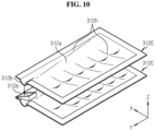
- FIG. 10 is a schematic rear perspective view of the components of a battery rack according to a sixth embodiment of the present disclosure.
- the battery rack according to the sixth embodiment of the present disclosure may further include a guide groove 312h recessed inward in the rack plate 312C.
- the guide groove 312h may be a groove which linearly extends along the mounting surface 312a of the rack plate 312C.
- the fire extinguishing liquid moving out of the pack housing 210 may be allowed to move along the guide groove 312h of the rack plate 312C.
- the rack plate 312C may be configured such that the fire extinguishing liquid moving out of the pack housing 210 moves to the extension portion 312b along the guide groove 312h and is discharged through the rear end of the rack plate 312C.
- the rack plate 312C includes the guide groove 312h configured to guide the movement of the fire extinguishing liquid moving out of the pack housing 210, thereby controlling the movement of the fire extinguishing liquid to a specific location of the rack plate 312C, and preventing the fire extinguishing liquid from being fed into the lower battery pack 200 due to the unexpected flow of the fire extinguishing liquid. Accordingly, it is possible to prevent the battery pack 200 in which thermal runaway or a fire did not occur from being contaminated with the fire extinguishing liquid. The present disclosure can re-use the battery pack 200 in which thermal runaway or a fire did not occur.
- the battery rack 300 when compared with the battery rack 300 of the first embodiment, may include a discharge portion 312p configured to discharge the fire extinguishing liquid falling from the upper battery pack 200.
- the discharge portion 312p may be in the shape of a conduit having an open top, extending in the upward diagonal direction.
- the discharge portion 312p may guide the falling fire extinguishing liquid to flow out to one side.
- the fire extinguishing liquid moving along the guide groove 312h formed in the upper rack plate 312C falls from the rear end of the rack plate 312C under gravity, at least a portion of the fire extinguishing liquid may be received in the discharge portion 312p of the lower rack plate 312C, and the received fire extinguishing liquid may move back to the right end along the conduit shape of the discharge portion 312p and may be discharged.
- the rack plate 312C includes the discharge portion 312p configured to receive the fire extinguishing liquid falling from the upper battery pack 200 and flow it out, thereby preventing the lower battery pack 200 in which thermal runaway or a fire did not occur from being contaminated with the fire extinguishing liquid. Accordingly, it is possible to re-use the battery pack 200 in which thermal runaway or a fire did not occur.
- FIG. 11 is a schematic diagram of the components of a battery rack according to a seventh embodiment of the present disclosure.
- the battery rack according to the seventh embodiment of the present disclosure may further include an absorption member 319 in the pack housing 210 of the battery pack 200D.
- the absorption member 319 may be configured to absorb the fire extinguishing liquid (M1 in FIG. 5 ).
- the absorption member 319 may be a sponge.
- the absorption member 319 may include a super absorbent fiber formed by spinning super absorbent resin into a mesh shape.
- the super absorbent resin may be configured to absorb the fire extinguishing liquid (water) that is heavier by about 500 to 1,000 times than its weight.
- the super absorbent resin may be a super absorbent resin product from LG Chem.
- the absorption member 319 may be made by simultaneously polymerizing acrylic acid and methyl acrylate as raw materials in water, extracting the resulting polymer and spinning into the shape of a mesh.
- the absorption member 319 may be interposed between the secondary batteries 110 disposed in the opposite direction to the sloping direction among the plurality of secondary batteries 110. For example, as shown in FIG. 11 , when the rack plate 312 slopes rearward (Y-axis direction), the fire extinguishing liquid in the pack housing 210 may fill the pack housing 210 from the rear part.
- the level of the fire extinguishing liquid at the front location in the pack housing 210 may be lower than that of the rear location in the pack housing 210. Accordingly, the use of the absorption member 319 makes it easy to sufficiently supply the fire extinguishing liquid between the plurality of secondary batteries 110, thereby effectively achieving the cooling or heat shielding of the secondary battery 110 disposed at the front location in the pack housing 210.
- the battery pack 200D may include the absorption member 319 between the secondary batteries 110 disposed in the opposite direction to the sloping direction among the plurality of secondary batteries 110 to absorb the fire extinguishing liquid, thereby distributing the fire extinguishing liquid in the pack housing 210 although the battery pack 200D is inclined. Accordingly, when thermal runaway or a fire occurs in the secondary battery 110 disposed in the opposite direction to the sloping direction in the pack housing 210, it is possible to effectively suppress the fire or thermal runaway through heat shielding by supplying the fire extinguishing liquid.
- FIG. 12 is a schematic front view of an energy storage system according to an embodiment of the present disclosure.
- the battery rack 300 may further include other components such as a Battery Management System (BMS) 350 inside or outside of the rack case 310.
- BMS Battery Management System
- the energy storage system 600 may include at least two battery racks 300.
- the at least two battery racks 300 may be arranged in a direction.
- the energy storage system 600 may include three battery racks 300 arranged in a direction, each battery rack 300 including a rack case 310.
- the energy storage system 600 may include a separate BMS 350 to control the charge/discharge of each of the three battery racks 300.
- the energy storage system 600 may include a coupling member configured to couple adjacent rack cases 310.
- Battery rack 600 Energy storage system 200: Battery pack 100: Cell assembly 110: Secondary battery 210: Pack housing 310: Rack case 312: Rack plate 312a: Mounting surface 312b: Extension portion 314: Front frame 316: Rear frame 313: Fixing bracket 312c: Stopper 317: Cover 312h: Guide groove 312p: Discharge portion 319: Absorption member
Landscapes
- Chemical & Material Sciences (AREA)
- Chemical Kinetics & Catalysis (AREA)
- Electrochemistry (AREA)
- General Chemical & Material Sciences (AREA)
- Engineering & Computer Science (AREA)
- Manufacturing & Machinery (AREA)
- Health & Medical Sciences (AREA)
- Public Health (AREA)
- Business, Economics & Management (AREA)
- Emergency Management (AREA)
- Battery Mounting, Suspending (AREA)
- Secondary Cells (AREA)
Description
- The present disclosure relates to a battery rack and an energy storage system comprising the same, and more particularly, to a battery rack for effectively preventing the spread of a fire or heat and re-using an undamaged battery pack when the fire or thermal runaway occurs while in use.
- Currently, commercially available secondary batteries include nickel-cadmium batteries, nickel-hydrogen batteries, nickel-zinc batteries, lithium secondary batteries and the like, and among them, lithium secondary batteries have little or no memory effect, and thus they are gaining more attention than nickel-based secondary batteries for their advantages that recharging may be done whenever it is convenient, the self-discharge rate is very low and the energy density is high.
- A lithium secondary battery primarily uses lithium-based oxide and a carbon material as a positive electrode active material and a negative electrode active material respectively. The lithium secondary battery includes an electrode assembly including a positive electrode plate and a negative electrode plate coated with the positive electrode active material and the negative electrode active material respectively with a separator interposed between the positive electrode plate and the negative electrode plate, and a packaging or a battery pouch case in which the electrode assembly is hermetically received together with an electrolyte solution.
- Recently, secondary batteries are widely used in not only small devices such as portable electronic devices, but also medium- and large-scale devices such as vehicles and energy storage systems. For use in medium- and large-scale device applications, many secondary batteries are electrically connected to increase the capacity and output. In particular, pouch-type secondary batteries are widely used in medium- and large-scale devices due to their easy-to-stack advantage.
- More recently, with the use as a source of energy and the growing need for large-capacity structures, there is an increasing demand for a battery rack including a plurality of battery packs, each including a plurality of secondary batteries electrically connected in series and/or in parallel, a battery module in which the plurality of secondary batteries is received, and a battery management system (BMS).
- The battery rack typically includes a metal rack case to protect the plurality of battery packs from external impacts or receive and store the battery packs. Recently, with the increasing demand for high capacity battery racks, the demand for battery racks including a plurality of battery packs is increasing.
- However, when thermal runaway occurs in a secondary battery of any one of the plurality of battery packs in the battery rack and the secondary battery burns or explodes, a larger explosion may occur due to the transfer of heat or flames to adjacent secondary batteries, so there have been many attempts to prevent the subsequent fires or explosions.
- Accordingly, there is a need for quick and complete fire extinguishing technology to rapidly handle thermal runaway when it occurs in a secondary battery within the battery rack.
- When a fire or thermal runaway occurs in any of the plurality of battery packs, the fire has been suppressed by feeding the fire extinguishing liquid to the battery pack in which the fire or thermal runaway occurred, but the fire extinguishing liquid is fed to a battery pack in which the fire did not occur and thus the corresponding battery pack is contaminated with the fire extinguishing liquid and cannot be re-used.
- Further prior art is described in
CN 110 649 194 ACN 207 818 832 U ,WO 2017/154462 A (forming the basis for the preamble of claim 1) , andCN 209 000 982 U . - The present disclosure is designed to solve the above-described problem, and therefore the present disclosure is directed to providing a battery rack for effectively preventing the spread of a fire or heat and re-using an undamaged battery pack when the fire or thermal runaway occurs while in use.
- These and other objects and advantages of the present disclosure may be understood by the following description, and will be apparent from the embodiments of the present disclosure.
- To achieve the above-described object, a battery rack according to the present disclosure includes a plurality of battery packs vertically arranged, each battery pack including a plurality of secondary batteries stacked in a direction, and a pack housing having an internal space to receive the plurality of secondary batteries and having a feed port for supplying a fire extinguishing liquid from a fire extinguishing liquid tank to said battery pack when an internal temperature in said battery pack equals or rises above a predetermined temperature, and a rack case having a receiving space to receive the plurality of battery packs, and including a plurality of rack plates, each having a mounting surface on which the battery pack is mounted, the mounting surface sloping at a predetermined angle with declining height as it goes in the sloping direction, and an extension portion having an end in the sloping direction extending further outward than the lower battery pack.
- The rack case may include a front frame disposed at a front end of the plurality of battery packs and including a post configured to support the ground, a rear frame disposed at a rear end of the plurality of battery packs and including a post configured to support the ground, and a fixing bracket coupled to the rack plate and coupled to the post of each of the front frame and the rear frame at a predetermined angle with declining height as it goes in the sloping direction.
- The extended end of the extension portion of the lower rack plate among the plurality of rack plates may be disposed at a more inward position than an end of the extension portion of the upper rack plate.
- The end in the sloping direction of the lower battery pack among the plurality of battery packs may be disposed at a more inward position than an end of the upper battery pack.
- The rack plate may include a stopper to keep the mounted battery pack from moving in the any one direction.
- The battery pack may further include a cover having an end in the sloping direction extending further outward than said battery pack to allow the fire extinguishing liquid falling from the upper rack plate to flow outward.
- The rack plate may have a guide groove to guide the movement of the fire extinguishing liquid moving out of the pack housing.
- The rack plate may include a discharge portion configured to receive the fire extinguishing liquid falling from the upper battery pack and flow it out.
- The battery rack may include an absorption member between the secondary batteries in the battery pack to absorb the fire extinguishing liquid.
- To achieve the above-described object, an energy storage system according to the present disclosure includes at least one battery rack.
- The solution of
claim 1 prevents the fire extinguishing liquid supplied to the specific battery pack among the plurality of battery packs from flowing into the lower battery pack when thermal runaway or a fire occurs in the specific battery pack. Accordingly, it is possible to solve the problem caused by the supply of the fire extinguishing liquid that is to say, the remaining battery pack except the battery pack in which thermal runaway or a fire occurred is wetted with the fire extinguishing liquid and cannot be re-used. - According to the solution of claim 3, when the fire extinguishing liquid is supplied, the fire extinguishing liquid moving out of the pack housing is discharged through the extension portion, and in this instance, since the extended length of the extension portion disposed at the lower position is shorter than that of the extension portion disposed at the higher position, the lower battery pack may avoid contamination by the fire extinguishing liquid falling in the direction of gravity from the extension portion disposed at the higher position.
- According to the solution of claim 4, when the fire extinguishing liquid is supplied to the battery pack, the fire extinguishing liquid moving out of the pack housing does not flow to the lower battery pack and may vertically fall by the gravity. That is, the battery pack may avoid contamination by the fire extinguishing liquid falling in the direction of gravity from the extension portion disposed at the higher position.
- The solution of claim 7 enables to control the movement of the fire extinguishing liquid to a specific location of the rack plate, and to prevent the fire extinguishing liquid from being fed into the lower battery pack due to the unexpected flow of the fire extinguishing liquid. Accordingly, it is possible to prevent the battery pack in which thermal runaway or a fire did not occur from being contaminated with the fire extinguishing liquid. The present disclosure can re-use the battery pack in which thermal runaway or a fire did not occur.
- The accompanying drawings illustrate preferred embodiments of the present disclosure, and together with the following detailed description, serve to provide a further understanding of the technical aspects of the present disclosure. However, the present disclosure should not be construed as being limited to the drawings.
-
FIG. 1 is a schematic perspective view of a battery rack according to an embodiment of the present disclosure. -
FIG. 2 is a schematic rear perspective view of a battery pack of a battery rack according to an embodiment of the present disclosure. -
FIG. 3 is a schematic perspective view of a cell assembly of a battery pack of a battery rack according to an embodiment of the present disclosure. -
FIG. 4 is a schematic partial rear perspective view of internal components of a rack case of a battery rack according to an embodiment of the present disclosure. -
FIG. 5 is a schematic diagram of components of a battery rack according to a first embodiment of the present disclosure. -
FIG. 6 is a schematic diagram of components of a battery rack according to a second embodiment of the present disclosure. -
FIG. 7 is a schematic diagram of components of a battery rack according to a third embodiment of the present disclosure. -
FIG. 8 is a schematic diagram of components of a battery rack according to a fourth embodiment of the present disclosure. -
FIG. 9 is a schematic diagram of components of a battery rack according to a fifth embodiment of the present disclosure. -
FIG. 10 is a schematic rear perspective view of components of a battery rack according to a sixth embodiment of the present disclosure. -
FIG. 11 is a schematic diagram of components of a battery rack according to a seventh embodiment of the present disclosure. -
FIG. 12 is a schematic front view of an energy storage system according to an embodiment of the present disclosure. - Hereinafter, the preferred embodiments of the present disclosure will be described in detail with reference to the accompanying drawings. Prior to the description, it should be understood that the terms or words used in the specification and the appended claims should not be construed as being limited to general and dictionary meanings, but rather interpreted based on the meanings and concepts corresponding to the technical aspects of the present disclosure on the basis of the principle that the inventor is allowed to define the terms appropriately for the best explanation.
- Therefore, the embodiments described herein and illustrations shown in the drawings are just a most preferred embodiment of the present disclosure, but not intended to fully describe the technical aspects of the present disclosure.
-
FIG. 1 is a schematic perspective view of a battery rack according to an embodiment of the present disclosure.FIG. 2 is a schematic rear perspective view of a battery pack of the battery rack according to an embodiment of the present disclosure.FIG. 3 is a schematic perspective view of a cell assembly of the battery pack of the battery rack according to an embodiment of the present disclosure. For reference, the positive and negative X-axis directions inFIG. 1 may be right and left directions. The positive and negative Z-axis directions inFIG. 1 may be up and down directions. The positive and negative Y-axis directions inFIG. 1 may be rear and front directions. - Referring to
FIGS. 1 to 3 , thebattery rack 300 of the present disclosure includes a plurality ofbattery packs 200 vertically arranged and arack case 310. - Specifically, each
battery pack 200 may include a plurality ofsecondary batteries 110 stacked in a direction. Thesecondary battery 110 may be a pouch-typesecondary battery 110. - In particular, the pouch-type
secondary battery 110 may include an electrode assembly (not shown), an electrolyte solution (not shown) and apouch 116. - Each
secondary battery 110 may stand in a direction that is approximately perpendicular to the ground with two wide surfaces disposed in the front-rear direction and sealing portions disposed in the up, down, left and right directions when viewed from the direction F (shown inFIG. 1 ). In other words, eachsecondary battery 110 may stand upright in the vertical direction. Unless otherwise specified herein, the up, down, front, rear, left, and right directions are defined when viewed from the direction F. - Here, the pouch may have a concave receiving portion. The electrode assembly and the electrolyte solution may be received in the receiving portion. Each pouch may include an outer insulating layer, a metal layer and an inner adhesive layer, and the inner adhesive layers adhere to each other at the edges of the pouch to form the sealing portions. A terrace portion may be formed at each of the left and right ends at which a
positive electrode lead 112 and anegative electrode lead 111 of thesecondary battery 110 are formed. - The electrode assembly may be an assembly of an electrode plate coated with an electrode active material and a separator, and may include at least one positive electrode plate and at least one negative electrode plate with the separator interposed between. The positive electrode plate of the electrode assembly may have a positive electrode tab, and at least one positive electrode tab may be connected to the
positive electrode lead 112. - Here, the
positive electrode lead 112 may have one end connected to the positive electrode tab and the other end exposed through the pouch, and the exposed portion may act as an electrode terminal of thesecondary battery 110, for example, a positive electrode terminal of thesecondary battery 110. - The negative electrode plate of the electrode assembly may have a negative electrode tab, and at least one negative electrode tab may be connected to the
negative electrode lead 111. Thenegative electrode lead 111 may have one end connected to the negative electrode tab and the other end exposed through the pouch, and the exposed portion may act as an electrode terminal of thesecondary battery 110, for example, a negative electrode terminal of thesecondary battery 110. - As shown in
FIG. 3 , when viewed from the direction F, thepositive electrode lead 112 and thenegative electrode lead 111 may be formed at the left and right ends with respect to the center of thesecondary battery 110. That is, thepositive electrode lead 112 may be provided at one end (the left end) with respect to the center of thesecondary battery 110. Thenegative electrode lead 111 may be provided at the other end (the right end) with respect to the center of thesecondary battery 110. - For example, as shown in
FIG. 3 , eachsecondary battery 110 of thecell assembly 100 may have thepositive electrode lead 112 and thenegative electrode lead 111 extending in the left-right direction. - Here, the terms representing the directions such as front, rear, left, right, up, and down may change depending on the position of the observer or the placement of the stated elements. However, in the specification, for convenience of description, the front, rear, left, right, up, and down directions are defined when viewed from the direction F.
- According to this configuration of the present disclosure, it is possible to increase the area of the electrode lead in one
secondary battery 110 without interruption between thepositive electrode lead 112 and thenegative electrode lead 111. - The
positive electrode lead 112 and thenegative electrode lead 111 may be formed in a plate shape. In particular, thepositive electrode lead 112 and thenegative electrode lead 111 may extend in the horizontal direction (X direction) with the wide surfaces standing upright in the front-rear direction. - Here, the 'horizontal direction' refers to a direction parallel to the ground when the
battery pack 200 is placed on the ground, and may be referred to as at least one direction on a plane perpendicular to the vertical direction. - However, the
battery pack 200 according to the present disclosure is not limited to the above-described pouch-typesecondary battery 110 and may use various types ofsecondary batteries 110 known at the time of filing the application. - The at least two
cell assemblies 100 may be arranged in the front-rear direction (Y-axis direction). - The
battery pack 200 may include abusbar assembly 270 including at least one busbar 272 configured to electrically connect the plurality ofsecondary batteries 110 and abusbar frame 276. Specifically, the busbar 272 may have an electrically conductive metal, for example, copper, aluminum and nickel. Thebusbar frame 276 may have a plastic material with low electrical conductivity. - The
pack housing 210 may have an internal space to receive thecell assembly 100 therein. Specifically, when viewed from the direction F ofFIG. 3 , thepack housing 210 may include atop cover 220, abase plate 240, afront cover 260 and arear cover 250. - Specifically, the
base plate 240 may have a larger area than the size of the lower surface of the at least twocell assemblies 100 to mount the at least twocell assemblies 100 thereon. Thebase plate 240 may be in the shape of a plate that extends in the horizontal direction. - The
top cover 220 may include anupper wall 224 and aside wall 226 extending downward from theupper wall 224. Theupper wall 224 may be in the shape of a plate that extends in the horizontal direction to cover the top of thecell assembly 100. Theside wall 226 may be in the shape of a plate that extends downward from the left and right ends of theupper wall 224 to cover the left and right sides of thecell assembly 100. - The
side wall 226 may be coupled to a portion of thebase plate 240. For example, as shown inFIG. 2 , thetop cover 220 may include theupper wall 224 in the shape of a plate that extends in the front-rear direction and the left-right direction. Thetop cover 220 may include twoside walls 226 extending downward from the left and right ends of theupper wall 224. The lower end of each of the twoside walls 226 may be coupled to the left and right ends of thebase plate 240. In this instance, the coupling method may be male-female coupling or weld coupling. - The
front cover 260 may be configured to cover the front side of the plurality ofsecondary batteries 110. For example, thefront cover 260 may be in the shape of a plate having a larger size than the size of the front side of the plurality ofsecondary batteries 110. The plate may stand in the vertical direction. - The
rear cover 250 may be configured to cover the rear side of thecell assembly 100. For example, therear cover 250 may be in the shape of a plate having a larger size than the size of the rear side of the plurality ofsecondary batteries 110. - The
pack housing 210 may have an internal space to receive the plurality ofsecondary batteries 110, and may be supplied with a fire extinguishing liquid when the internal temperature equals or rises above a predetermined temperature. Here, the predetermined temperature may be 300°C or above. - Specifically, the
rear cover 250 disposed at the rear side of each of the at least twobattery packs 200 may include afeed port 264 through which the fire extinguishing liquid is fed. Thefeed port 264 may be in communication with arefrigerant movement path 211. That is, thefeed port 264 may be in communication with therefrigerant movement path 211 disposed on the left and right sides of thecell assembly 100. - The
pack housing 210 may receive thecell assembly 100 inside, and have anopening 215 to through which the outdoor air enters and exits thepack housing 210. For example, as shown inFIG. 2 , theopening 215 may include aninlet 213 and anoutlet 212. Each of theinlet 213 and theoutlet 212 may be formed in a portion of thepack housing 210. Theinlet 213 may be configured to allow the outdoor air to be fed into thepack housing 210. Theoutlet 212 may be formed in a portion of thepack housing 210 and configured to allow the fed air to exit. - Referring back to
FIG. 1 , thebattery rack 300 may include a fire extinguishingliquid tank 320, apipe 330 and afire extinguishing valve 340. - To begin with, the fire extinguishing
liquid tank 320 may store the fire extinguishing liquid (not shown) therein. For example, the fire extinguishing liquid may be an inorganic salt enriched solution such as potassium carbonate, a chemical foam, an air foam, carbon dioxide or water. The fire extinguishingliquid tank 320 may store compressed gas therein to spray the fire extinguishing liquid with proper pressure or move the fire extinguishing liquid along thepipe 330. - For example, the capacity of the fire extinguishing
liquid tank 320 may be 59 L, the compressed gas may be 8 bar nitrogen, and the fire extinguishing liquid may be 40 L of water. Here, in case that water is used as the fire extinguishing liquid, water has a cooling and fire extinguishing effect and a heat shielding effect when sprayed into thebattery pack 200, so especially when high temperature gas and flames are generated due to thermal runaway, it is effective in preventing thermal propagation. Accordingly, it is possible to effectively prevent the propagation of fires or thermal runaway between the plurality of battery packs 100. - The
pipe 330 may be connected to supply the fire extinguishing liquid from the fire extinguishingliquid tank 320 to each of the at least two battery packs 200. For example, thepipe 330 may include a material having resistance to corrosion by water. For example, thepipe 330 may include stainless steel. One end of thepipe 330 may be connected to an outlet (321 inFIG. 1 ) of the fire extinguishingliquid tank 320. The other end of thepipe 330 may be connected to thefeed port 264 of thepack housing 210. - When gas (air) in the
battery pack 200 rises above the predetermined temperature, thefire extinguishing valve 340 may be configured to supply the fire extinguishing liquid from the fire extinguishingliquid tank 320 into thebattery pack 200. That is, thefire extinguishing valve 340 may be an active valve having an open outlet through which the fire extinguishing liquid is fed into thebattery pack 200 at the predetermined temperature or above. The active valve may be, for example, a control valve, a pneumatic valve and a solenoid valve with remote control. -
FIG. 4 is a schematic rear perspective view of the internal components of the rack case of the battery rack according to an embodiment of the present disclosure.FIG. 5 is a schematic diagram of the components of the battery rack according to a first embodiment of the present disclosure. - Referring to
FIGS. 4 and5 together withFIG. 1 , therack case 310 may have a receiving space having two open sides to receive and store each of the plurality of battery packs 200. The plurality of battery packs 200 may be vertically arranged in therack case 310. The plurality of battery packs 200 may be vertically arranged in therack case 310, spaced a predetermined distance apart from one another. - The
rack case 310 includes arack plate 312 on which thebattery pack 200 is mounted. Specifically, therack plate 312 includes a mountingsurface 312a and anextension portion 312b. More specifically, the mountingsurface 312a may have an area that is equivalent to or larger than the lower surface of thebattery pack 200. The mountingsurface 312a slopes at a predetermined angle relative to a horizontal line P1 such that the height declines as it goes in the sloping direction. That is, therack plate 312 is fixed to other components of therack case 310 with the declining height of the mountingsurface 312a as it goes in the sloping direction. For example, as shown inFIG. 4 , therack plate 312 may be fixed to each of afront frame 314 and arear frame 316 of therack case 310 such that the height of the mountingsurface 312a declines as it goes rearward. For example, therack plate 312 may slope at 1° to 3° with respect to the horizon. - The
extension portion 312b of theupper rack plate 312 has an end in the sloping direction extending further outward than thelower battery pack 200. For example, therack plate 312 may include theextension portion 312b at the rear end. For example, therack plate 312 may be configured to allow the fire extinguishing liquid M1 to flow along the slope of the mountingsurface 312a and out of theextension portion 312b in the sloping direction. - According to this configuration of the present disclosure, the present disclosure includes the
rack case 310 having the receiving space to receive the plurality of battery packs 200, and including the plurality ofrack plates 312 including the mountingsurface 312a on which thebattery pack 200 is mounted, the mounting surface sloping at a predetermined angle with the declining height as it goes in the sloping direction, and theextension portion 312b having an end in the sloping direction extending further outward than thelower battery pack 200, thereby preventing the fire extinguishing liquid M1 supplied to thespecific battery pack 200 among the plurality of battery packs from flowing into thelower battery pack 200 when thermal runaway or a fire occurs in thespecific battery pack 200. Accordingly, it is possible to solve the problem caused by the supply of the fire extinguishing liquid M1, that is to say, the remainingbattery pack 200 except thebattery pack 200 in which thermal runaway or a fire occurred is wetted with the fire extinguishing liquid M1 and cannot be re-used. - Referring back to
FIGS. 1 to 5 , therack case 310 may include thefront frame 314, therear frame 316 and a fixingbracket 313. Thefront frame 314 may be disposed at the front end of the plurality of battery packs 200. Thefront frame 314 may include apost 314p configured to support the ground. - The
rear frame 316 may be disposed at the rear end of the plurality of battery packs 200. Therear frame 316 may include apost 316p configured to support the ground. - The fixing
bracket 313 may be coupled to therack plate 312. That is, therack plate 312 may be coupled to the bottom of the fixingbracket 313. For example, therack plate 312 and the fixingbracket 313 may be weld-coupled to each other. The fixingbracket 313 may be in the shape of a plate that is bent at approximately 90° in the letter 'L' shape. The fixingbracket 313 may extend in the front-rear direction. The front and rear ends of the fixingbracket 313 may be bolt-coupled to thefront frame 314 and therear frame 316 respectively. - The fixing
bracket 313 may be coupled to theposts front frame 314 and therear frame 316. In this instance, the fixingbracket 313 may be fixed to theposts front frame 314 and therear frame 316 at a predetermined angle with the declining height as it goes in the sloping direction. For example, as shown inFIG. 4 , the front end of the fixingbracket 313 coupled to thefront frame 314 may be coupled to the higher location than the rear end of the fixingbracket 313 coupled to therear frame 316. -
FIG. 6 is a schematic diagram of the components of a battery rack according to a second embodiment of the present disclosure. - Referring to
FIG. 6 together withFIGS. 1 and4 , in the battery rack according to another embodiment of the present disclosure, the extended end of the extension portion 312b2 of thelower rack plate 312A among the plurality ofrack plates 312A may be disposed on the more inward position than the end of the extension portion 312b1 of theupper rack plate 312A. For example, as shown inFIG. 6 , therack plate 312A disposed at the lower location of therack case 310 among therack plates 312A vertically arranged may have the extension portion 312b1 extending rearward (Y-axis direction) that is shorter than the extension portion 312b2 of theupper rack plate 312A. Accordingly, the extended end of the extension portion 312b2 of thelower rack plate 312A may be disposed on the more inward position than the end of the extension portion 312b1 of theupper rack plate 312A. - The
rack case 310 may have the extended length of the extension portion of therack plate 312A that gradually becomes shorter as it goes downward with respect to the extension portion of therack plate 312A having thetopmost battery pack 200 mounted thereon. That is, the extended length of the extension portion of thetopmost rack plate 312A may be longest, and the extended length of the extension portion of thebottommost rack plate 312A may be shortest. - According to this configuration of the present disclosure, the extended end of the extension portion 312b2 of the
lower rack plate 312A among the plurality ofrack plates 312A is disposed on the more inward position than the end of the extension portion 312b1 of theupper rack plate 312A, so when the fire extinguishing liquid is supplied, the fire extinguishing liquid moving out of thepack housing 210 flows along the slope of the mountingsurface 312a of therack plate 312A and is discharged in the sloping direction through the extension portion 312b1, and in this instance, since the extended length of the extension portion 312b2 disposed at the lower position is shorter than that of the extension portion 312b1 disposed at the higher position, thelower battery pack 200 may avoid contamination by the fire extinguishing liquid falling in the direction of gravity from the extension portion 312b1 disposed at the higher position. -
FIG. 7 is a schematic diagram of the components of a battery rack according to a third embodiment of the present disclosure. - Referring to
FIG. 7 together withFIGS. 1 and4 , a plurality of battery packs 200B1, 200B2 and a plurality of rack plates 312B1, 312B2 provided in the battery rack of the third embodiment of the present disclosure may have different positions. The plurality of rack plates 312B1, 312B2 provided in the battery rack of the third embodiment may have the same extended length as opposed to therack plates 312A of the second embodiment ofFIG. 6 . - Specifically, among the plurality of battery packs 200B1, 200B2, the end in the sloping direction of the lower battery pack 200B2 may be disposed on the more inward position than the end of the upper battery pack 200B1. That is, the extended lengths of the
extension portions 312b of therack plates 312 provided in the battery rack of the third embodiment may be the same, but therack plate 312 disposed higher may be spaced a predetermined distance apart toward the front than thelower rack plate 312. - For example, as shown in
FIG. 7 , among the plurality of battery packs 200 vertically arranged, the battery pack 200B1 may be disposed at the more front position than the lower battery pack 200B2. That is, thebattery rack 300 of the present disclosure may have the receiving location of thebattery pack 200 of therack case 310 disposed at the more front position as thebattery pack 200 is disposed at the lower position. The location of theextension portion 312b of therack plate 312 may be gradually extended forward as it goes downward. - According to this configuration of the present disclosure, among the plurality of battery packs 200, the end in the sloping direction of the
lower battery pack 200 is disposed on the more inward position than the end of theupper battery pack 200, so when the fire extinguishing liquid is supplied to thebattery pack 200, the fire extinguishing liquid moving out of thepack housing 210 does not flow to thelower battery pack 200 and may vertically fall by the gravity. That is, thebattery pack 200 may avoid contamination by the fire extinguishing liquid falling in the direction of gravity from theextension portion 312b disposed at the higher position. -
FIG. 8 is a schematic diagram of the components of a battery rack according to a fourth embodiment of the present disclosure. - Referring to
FIG. 8 together withFIGS. 1 and4 , the battery rack according to the fourth embodiment of the present disclosure may have astopper 312c to keep themounted battery pack 200 from moving in the sloping direction. For example, thestopper 312c may extend upward from the mountingsurface 312a of therack plate 312. Thestopper 312c may be in the shape of a plate that stands upright to support the rear side of thepack housing 210 forwards. - According to this configuration of the present disclosure, the
rack plate 312 includes thestopper 312c to keep themounted battery pack 200 from moving in the sloping direction, thereby preventing thebattery pack 200 from moving in the sloping direction along the slope of the mountingsurface 312a of therack plate 312 and out of therack case 310. Accordingly, it is possible to increase the safety of thebattery rack 300 of the present disclosure. -
FIG. 9 is a schematic diagram of the components of a battery rack according to a fifth embodiment of the present disclosure. - Referring to
FIG. 9 together withFIGS. 1 and4 , when comparing the battery rack according to the fifth embodiment of the present disclosure with thebattery rack 300 according to the first embodiment, thebattery pack 200 may further include acover 317 on thepack housing 210. Thecover 317 may be configured to allow the fire extinguishing liquid falling from theupper rack plate 312 to flow outward. - The
cover 317 may be in the shape of a plate having the similar width to therack plate 312. Thecover 317 may extend outward from the end of thebattery pack 200. For example, as shown inFIG. 9 , thecover 317 extending rearward from the rear end of thebattery pack 200 may be provided at the rear end of thebattery pack 200. - According to this configuration of the present disclosure, the battery rack according to the fifth embodiment of the present disclosure includes the
cover 317 extending outward from the end of thebattery pack 200 to allow the fire extinguishing liquid falling from therack plate 312 to flow outward, thereby shielding the fire extinguishing liquid falling from theupper rack plate 312, and preventing thebattery pack 200 in which thermal runaway or a fire did not occur from being contaminated with the fire extinguishing liquid. Accordingly, it is possible to re-use thebattery pack 200 in which thermal runaway or a fire did not occur. -
FIG. 10 is a schematic rear perspective view of the components of a battery rack according to a sixth embodiment of the present disclosure. - Referring to
FIG. 10 together withFIGS. 1 and4 , when compared with the battery rack of the first embodiment ofFIG. 4 , the battery rack according to the sixth embodiment of the present disclosure may further include aguide groove 312h recessed inward in therack plate 312C. Specifically, theguide groove 312h may be a groove which linearly extends along the mountingsurface 312a of therack plate 312C. When the fire extinguishing liquid is supplied in the event of thermal runaway or a fire in thebattery pack 200, the fire extinguishing liquid moving out of thepack housing 210 may be allowed to move along theguide groove 312h of therack plate 312C. For example, as shown inFIG. 10 , therack plate 312C may be configured such that the fire extinguishing liquid moving out of thepack housing 210 moves to theextension portion 312b along theguide groove 312h and is discharged through the rear end of therack plate 312C. - According to this configuration of the present disclosure, the
rack plate 312C includes theguide groove 312h configured to guide the movement of the fire extinguishing liquid moving out of thepack housing 210, thereby controlling the movement of the fire extinguishing liquid to a specific location of therack plate 312C, and preventing the fire extinguishing liquid from being fed into thelower battery pack 200 due to the unexpected flow of the fire extinguishing liquid. Accordingly, it is possible to prevent thebattery pack 200 in which thermal runaway or a fire did not occur from being contaminated with the fire extinguishing liquid. The present disclosure can re-use thebattery pack 200 in which thermal runaway or a fire did not occur. - Referring back to
FIG. 10 , when compared with thebattery rack 300 of the first embodiment, thebattery rack 300 according to the sixth embodiment of the present disclosure may include a discharge portion 312p configured to discharge the fire extinguishing liquid falling from theupper battery pack 200. For example, the discharge portion 312p may be in the shape of a conduit having an open top, extending in the upward diagonal direction. When the fire extinguishing liquid falls from theupper rack plate 312C under gravity, the discharge portion 312p may guide the falling fire extinguishing liquid to flow out to one side. - For example, as shown in
FIG. 10 , after the fire extinguishing liquid moving along theguide groove 312h formed in theupper rack plate 312C falls from the rear end of therack plate 312C under gravity, at least a portion of the fire extinguishing liquid may be received in the discharge portion 312p of thelower rack plate 312C, and the received fire extinguishing liquid may move back to the right end along the conduit shape of the discharge portion 312p and may be discharged. - According to this configuration of the present disclosure, the
rack plate 312C includes the discharge portion 312p configured to receive the fire extinguishing liquid falling from theupper battery pack 200 and flow it out, thereby preventing thelower battery pack 200 in which thermal runaway or a fire did not occur from being contaminated with the fire extinguishing liquid. Accordingly, it is possible to re-use thebattery pack 200 in which thermal runaway or a fire did not occur. -
FIG. 11 is a schematic diagram of the components of a battery rack according to a seventh embodiment of the present disclosure. - Referring to
FIG. 11 together withFIGS. 2 and5 , when compared with thebattery rack 300 of the first embodiment, the battery rack according to the seventh embodiment of the present disclosure may further include anabsorption member 319 in thepack housing 210 of thebattery pack 200D. Theabsorption member 319 may be configured to absorb the fire extinguishing liquid (M1 inFIG. 5 ). Theabsorption member 319 may be a sponge. Alternatively, theabsorption member 319 may include a super absorbent fiber formed by spinning super absorbent resin into a mesh shape. Here, the super absorbent resin may be configured to absorb the fire extinguishing liquid (water) that is heavier by about 500 to 1,000 times than its weight. For example, the super absorbent resin may be a super absorbent resin product from LG Chem. For example, theabsorption member 319 may be made by simultaneously polymerizing acrylic acid and methyl acrylate as raw materials in water, extracting the resulting polymer and spinning into the shape of a mesh. - The
absorption member 319 may be interposed between thesecondary batteries 110 disposed in the opposite direction to the sloping direction among the plurality ofsecondary batteries 110. For example, as shown inFIG. 11 , when therack plate 312 slopes rearward (Y-axis direction), the fire extinguishing liquid in thepack housing 210 may fill thepack housing 210 from the rear part. - Since the
battery pack 200D is placed in a rearward incline, the level of the fire extinguishing liquid at the front location in thepack housing 210 may be lower than that of the rear location in thepack housing 210. Accordingly, the use of theabsorption member 319 makes it easy to sufficiently supply the fire extinguishing liquid between the plurality ofsecondary batteries 110, thereby effectively achieving the cooling or heat shielding of thesecondary battery 110 disposed at the front location in thepack housing 210. - According to this configuration of the present disclosure, the
battery pack 200D may include theabsorption member 319 between thesecondary batteries 110 disposed in the opposite direction to the sloping direction among the plurality ofsecondary batteries 110 to absorb the fire extinguishing liquid, thereby distributing the fire extinguishing liquid in thepack housing 210 although thebattery pack 200D is inclined. Accordingly, when thermal runaway or a fire occurs in thesecondary battery 110 disposed in the opposite direction to the sloping direction in thepack housing 210, it is possible to effectively suppress the fire or thermal runaway through heat shielding by supplying the fire extinguishing liquid. -
FIG. 12 is a schematic front view of an energy storage system according to an embodiment of the present disclosure. - Referring to
FIG. 12 together withFIG. 1 , thebattery rack 300 may further include other components such as a Battery Management System (BMS) 350 inside or outside of therack case 310. - The energy storage system 600 according to an embodiment of the present disclosure may include at least two battery racks 300. The at least two
battery racks 300 may be arranged in a direction. For example, as shown inFIG. 12 , the energy storage system 600 may include threebattery racks 300 arranged in a direction, eachbattery rack 300 including arack case 310. Additionally, the energy storage system 600 may include aseparate BMS 350 to control the charge/discharge of each of the threebattery racks 300. The energy storage system 600 may include a coupling member configured to coupleadjacent rack cases 310. - The terms indicating directions as used herein such as upper, lower, left, right, front and rear are used for convenience of description only, and it is obvious to those skilled in the art that the term may change depending on the position of the stated element or an observer.
-
300: Battery rack 600: Energy storage system 200: Battery pack 100: Cell assembly 110: Secondary battery 210: Pack housing 310: Rack case 312: Rack plate 312a: Mounting surface 312b: Extension portion 314: Front frame 316: Rear frame 313: Fixing bracket 312c: Stopper 317: Cover 312h: Guide groove 312p: Discharge portion 319: Absorption member
Claims (10)
- A battery rack (300), comprising:a plurality of battery packs (200) vertically arranged, each battery pack (200) including a plurality of secondary batteries (110) stacked in a direction, and a pack housing (210) having an internal space to receive the plurality of secondary batteries (110) and having a feed port (264) for supplying a fire extinguishing liquid from a fire extinguishing liquid tank (320) to said battery pack (200) when an internal temperature in said battery pack (200) equals or rises above a predetermined temperature; anda rack case (310) having a receiving space to receive the plurality of battery packs (200),characterised in that said rack case (310) includes in said receiving space a plurality of rack plates (312), each having a mounting surface (312a) on which the battery pack (200) is mounted, the mounting surface (312a) sloping at a predetermined angle with declining height as it goes in the sloping direction, and an extension portion (312b) having an end in the sloping direction extending further outward than the lower battery pack (200).
- The battery rack (300) according to claim 1, wherein the rack case (310) includes:a front frame (314) disposed at a front end of the plurality of battery packs (200) and including a post (314p) configured to support the ground;a rear frame (316) disposed at a rear end of the plurality of battery packs (200) and including a post (316p) configured to support the ground; anda fixing bracket (313) coupled to the rack plate (312) and coupled to the post (314p; 316p) of each of the front frame (314) and the rear frame (316) at a predetermined angle with declining height as it goes in the sloping direction.
- The battery rack (300) according to claim 1, wherein the extended end (312b2) of the extension portion (312b) of the lower rack plate (312A) among the plurality of rack plates (312) is disposed at a more inward position than an end of the extension portion (312b1) of the upper rack plate (312A).
- The battery rack (300) according to claim 1, wherein the end in the sloping direction of the lower battery pack (200B2) among the plurality of battery packs (200B1, 200B2) is disposed at a more inward position than an end of the upper battery pack (200B1).
- The battery rack (300) according to claim 1, wherein the rack plate (312) includes a stopper (312c) to keep the mounted battery pack (200) from moving in the sloping direction.
- The battery rack (300) according to claim 1, wherein the battery pack (200) further includes a cover (317) having an end in the sloping direction extending further outward than said battery pack (200) , to allow the fire extinguishing liquid falling from the upper rack plate (312) to flow outward.
- The battery rack (300) according to claim 1, wherein the rack plate (312C) has a guide groove (312h) to guide the movement of the fire extinguishing liquid moving out of the pack housing (210).
- The battery rack (300) according to claim 7, wherein the rack plate (312) includes a discharge portion (312p) configured to receive fire extinguishing liquid falling from an upper battery pack (200) and to flow it out.
- The battery rack (300) according to claim 8, wherein said battery pack (200), which includes said plurality of secondary batteries (110), comprises an end in the sloping direction, and wherein an absorption member (319) is interposed between the secondary batteries (110) that are disposed at the opposite end of the battery pack (200), to absorb fire extinguishing liquid.
- An energy storage system comprising at least one battery rack (300) according to any one of claims 1 to 9.
Applications Claiming Priority (2)
| Application Number | Priority Date | Filing Date | Title |
|---|---|---|---|
| KR1020200027372A KR102668862B1 (en) | 2020-03-04 | 2020-03-04 | Battery Rack And Power Storage System Comprising the Same |
| PCT/KR2021/002712 WO2021177762A1 (en) | 2020-03-04 | 2021-03-04 | Battery rack and power storage device comprising same |
Publications (3)
| Publication Number | Publication Date |
|---|---|
| EP4024581A1 EP4024581A1 (en) | 2022-07-06 |
| EP4024581A4 EP4024581A4 (en) | 2023-04-19 |
| EP4024581B1 true EP4024581B1 (en) | 2024-11-13 |
Family
ID=77612991
Family Applications (1)
| Application Number | Title | Priority Date | Filing Date |
|---|---|---|---|
| EP21764281.8A Active EP4024581B1 (en) | 2020-03-04 | 2021-03-04 | Battery rack and energy storage system comprising the same |
Country Status (9)
| Country | Link |
|---|---|
| US (1) | US12261312B2 (en) |
| EP (1) | EP4024581B1 (en) |
| JP (1) | JP7214019B2 (en) |
| KR (1) | KR102668862B1 (en) |
| CN (1) | CN114303280B (en) |
| ES (1) | ES2998192T3 (en) |
| HU (1) | HUE069389T2 (en) |
| PL (1) | PL4024581T3 (en) |
| WO (1) | WO2021177762A1 (en) |
Families Citing this family (10)
| Publication number | Priority date | Publication date | Assignee | Title |
|---|---|---|---|---|
| CN114256558B (en) * | 2021-11-25 | 2025-09-23 | 星链正储(玉溪)新能源科技有限公司 | A large-capacity battery energy storage system |
| KR102747564B1 (en) * | 2021-12-09 | 2025-01-09 | 주식회사 정우엔지니어링 | Tray slide storage device of energy storage device |
| KR102936348B1 (en) * | 2022-05-02 | 2026-03-06 | 주식회사 엘지에너지솔루션 | Battery rack having a drainage structure and energy storage system including the same |
| US20250030141A1 (en) * | 2022-05-02 | 2025-01-23 | Lg Energy Solution, Ltd. | Energy storage system |
| US12580264B2 (en) | 2022-11-18 | 2026-03-17 | Moment Energy Inc. | Battery tray |
| CN117810568A (en) * | 2023-12-28 | 2024-04-02 | 中国华能集团清洁能源技术研究院有限公司 | Energy storage device based on thermal runaway protection |
| US12308674B1 (en) * | 2024-01-19 | 2025-05-20 | Moment Energy Inc. | Active energy balancing for energy storage systems |
| CN223039069U (en) * | 2024-04-08 | 2025-06-27 | 宁德时代新能源科技股份有限公司 | Batteries and energy storage devices |
| CN118842165B (en) * | 2024-09-20 | 2025-04-25 | 深圳市乐惠应急科技有限公司 | An emergency power supply with protection function |
| CN119746313B (en) * | 2025-03-06 | 2025-05-13 | 深圳市沃尔德新能源有限公司 | A new energy storage cabinet and energy storage method thereof |
Citations (3)
| Publication number | Priority date | Publication date | Assignee | Title |
|---|---|---|---|---|
| JP5761078B2 (en) * | 2012-02-29 | 2015-08-12 | 株式会社デンソー | Battery package |
| WO2021136875A1 (en) * | 2019-12-30 | 2021-07-08 | Latauspolku Oy | Battery cabinet and method of fire safely storing a battery |
| EP3968446A1 (en) * | 2020-03-04 | 2022-03-16 | Lg Energy Solution, Ltd. | Battery rack and energy storage device comprising battery rack |
Family Cites Families (30)
| Publication number | Priority date | Publication date | Assignee | Title |
|---|---|---|---|---|
| JP4116703B2 (en) * | 1998-07-31 | 2008-07-09 | 古河電池株式会社 | Storage battery mount |
| JP3403964B2 (en) | 1999-01-08 | 2003-05-06 | 古河電池株式会社 | Cubicle type battery panel |
| KR101029021B1 (en) | 2005-12-02 | 2011-04-14 | 주식회사 엘지화학 | High Cooling Battery Module |
| US20080292950A1 (en) * | 2007-05-24 | 2008-11-27 | Sanyo Electric Co., Ltd. | Battery module |
| JP5618641B2 (en) | 2010-06-07 | 2014-11-05 | 能美防災株式会社 | Fire extinguisher |
| DE102010034825A1 (en) | 2010-08-19 | 2012-02-23 | Li-Tec Battery Gmbh | Electrochemical energy storage |
| US20140017528A1 (en) * | 2011-03-31 | 2014-01-16 | Yuji Uehara | Rack-mount power supply device and battery pack including detachable connector |
| KR101358762B1 (en) * | 2011-05-31 | 2014-02-10 | 주식회사 엘지화학 | Battery cooling system and Battery rack applied for it |
| JP5979908B2 (en) | 2012-02-24 | 2016-08-31 | キヤノン株式会社 | Photomask and semiconductor device manufacturing method |
| JP2013206642A (en) * | 2012-03-28 | 2013-10-07 | Hitachi Ltd | Battery pack and battery system |
| KR20150038990A (en) | 2013-10-01 | 2015-04-09 | 주식회사 엘지화학 | Energy Storage Device Employed with Double Safety System |
| JP2015122166A (en) | 2013-12-20 | 2015-07-02 | 三菱重工業株式会社 | Battery rack and cooling method of secondary battery disposed in the same |
| KR101584295B1 (en) | 2014-07-03 | 2016-01-25 | 인셀(주) | Battery System Having Rack Structure |
| KR101778666B1 (en) * | 2014-09-29 | 2017-09-14 | 주식회사 엘지화학 | Energy Storage Apparatus of Combined Cooling Manner |
| JP6412456B2 (en) | 2015-03-31 | 2018-10-24 | 昭和電工株式会社 | Secondary battery cooling system |
| JP2019075191A (en) * | 2016-03-08 | 2019-05-16 | パナソニックIpマネジメント株式会社 | Power storage device |
| JP6782435B2 (en) * | 2016-03-10 | 2020-11-11 | パナソニックIpマネジメント株式会社 | Power storage device |
| US11705593B2 (en) * | 2016-12-26 | 2023-07-18 | Panasonic Intellectual Property Management Co., Ltd. | Rack type power source device |
| JP6662324B2 (en) | 2017-02-17 | 2020-03-11 | トヨタ自動車株式会社 | Battery pack |
| KR200489617Y1 (en) | 2017-09-29 | 2019-07-12 | 농업회사법인 홍성풀무 주식회사 | Noodles figuration device |
| CN207818832U (en) * | 2018-01-26 | 2018-09-04 | 北京匠芯电池科技有限公司 | A kind of fixed structure with battery pack automatic spring function |
| KR102437159B1 (en) | 2018-09-04 | 2022-08-26 | 주식회사 엘지화학 | Transmission Variable Device |
| US11495862B2 (en) * | 2018-09-21 | 2022-11-08 | Design Science Technology Llc | Safe transport and storage of energy storage devices |
| CN209000982U (en) * | 2018-10-30 | 2019-06-18 | 腾讯科技(深圳)有限公司 | Battery cupboard |
| US20200243813A1 (en) * | 2019-01-29 | 2020-07-30 | Sinexcel, Inc. | Compact battery-based energy storage |
| CN109743006B (en) | 2019-03-11 | 2024-05-24 | 苏州科瑞达智能科技有限公司 | Cooling water guiding device for photovoltaic cell assembly |
| US10511001B1 (en) * | 2019-03-18 | 2019-12-17 | Sinexcel Inc. | Compact battery-based energy storage systems |
| CN110010810A (en) * | 2019-03-22 | 2019-07-12 | 中国电力科学研究院有限公司 | A kind of energy-storage battery cabinet with fire-fighting structure |
| US10916818B2 (en) * | 2019-06-21 | 2021-02-09 | Baidu Usa Llc | Self-activating thermal management system for battery pack |
| CN110649194A (en) * | 2019-09-05 | 2020-01-03 | 国网湖南省电力有限公司 | Energy storage battery container, battery energy storage fire-fighting system and application method thereof |
-
2020
- 2020-03-04 KR KR1020200027372A patent/KR102668862B1/en active Active
-
2021
- 2021-03-04 HU HUE21764281A patent/HUE069389T2/en unknown
- 2021-03-04 JP JP2021578110A patent/JP7214019B2/en active Active
- 2021-03-04 CN CN202180005075.7A patent/CN114303280B/en active Active
- 2021-03-04 EP EP21764281.8A patent/EP4024581B1/en active Active
- 2021-03-04 ES ES21764281T patent/ES2998192T3/en active Active
- 2021-03-04 WO PCT/KR2021/002712 patent/WO2021177762A1/en not_active Ceased
- 2021-03-04 US US17/790,669 patent/US12261312B2/en active Active
- 2021-03-04 PL PL21764281.8T patent/PL4024581T3/en unknown
Patent Citations (3)
| Publication number | Priority date | Publication date | Assignee | Title |
|---|---|---|---|---|
| JP5761078B2 (en) * | 2012-02-29 | 2015-08-12 | 株式会社デンソー | Battery package |
| WO2021136875A1 (en) * | 2019-12-30 | 2021-07-08 | Latauspolku Oy | Battery cabinet and method of fire safely storing a battery |
| EP3968446A1 (en) * | 2020-03-04 | 2022-03-16 | Lg Energy Solution, Ltd. | Battery rack and energy storage device comprising battery rack |
Also Published As
| Publication number | Publication date |
|---|---|
| JP7214019B2 (en) | 2023-01-27 |
| JP2022539404A (en) | 2022-09-08 |
| HUE069389T2 (en) | 2025-03-28 |
| ES2998192T3 (en) | 2025-02-19 |
| PL4024581T3 (en) | 2025-04-07 |
| CN114303280A (en) | 2022-04-08 |
| US12261312B2 (en) | 2025-03-25 |
| WO2021177762A1 (en) | 2021-09-10 |
| KR20210112164A (en) | 2021-09-14 |
| KR102668862B1 (en) | 2024-05-22 |
| EP4024581A4 (en) | 2023-04-19 |
| EP4024581A1 (en) | 2022-07-06 |
| AU2021231265A1 (en) | 2022-04-21 |
| CN114303280B (en) | 2025-03-07 |
| US20230040296A1 (en) | 2023-02-09 |
Similar Documents
| Publication | Publication Date | Title |
|---|---|---|
| EP4024581B1 (en) | Battery rack and energy storage system comprising the same | |
| US20240079721A1 (en) | Battery module, battery rack comprising same, and power storage device | |
| KR102775048B1 (en) | Battery Pack Having Fire Extinguishing Unit | |
| EP3989339B1 (en) | Energy storage system | |
| EP4007050B1 (en) | Battery pack, battery rack comprising same, and power storage system | |
| US12274902B2 (en) | Battery module comprising absorption member, battery rack comprising same, and power storage system | |
| US12463273B2 (en) | Battery module, battery rack comprising same, and power storage device | |
| KR102730166B1 (en) | Battery Rack, Energy Storage System, and Power Generation System | |
| JP7417764B2 (en) | Battery racks, power storage devices, and power generation systems | |
| US11171383B1 (en) | Battery module | |
| AU2021231265B2 (en) | Battery rack and energy storage system comprising the same | |
| KR20240097567A (en) | Battery pack suitable for water drain |
Legal Events
| Date | Code | Title | Description |
|---|---|---|---|
| STAA | Information on the status of an ep patent application or granted ep patent |
Free format text: STATUS: THE INTERNATIONAL PUBLICATION HAS BEEN MADE |
|
| PUAI | Public reference made under article 153(3) epc to a published international application that has entered the european phase |
Free format text: ORIGINAL CODE: 0009012 |
|
| STAA | Information on the status of an ep patent application or granted ep patent |
Free format text: STATUS: REQUEST FOR EXAMINATION WAS MADE |
|
| 17P | Request for examination filed |
Effective date: 20220331 |
|
| AK | Designated contracting states |
Kind code of ref document: A1 Designated state(s): AL AT BE BG CH CY CZ DE DK EE ES FI FR GB GR HR HU IE IS IT LI LT LU LV MC MK MT NL NO PL PT RO RS SE SI SK SM TR |
|
| A4 | Supplementary search report drawn up and despatched |
Effective date: 20230317 |
|
| RIC1 | Information provided on ipc code assigned before grant |
Ipc: A62C 35/11 20060101ALI20230313BHEP Ipc: H01M 50/60 20210101ALI20230313BHEP Ipc: H01M 50/691 20210101ALI20230313BHEP Ipc: H01M 50/251 20210101ALI20230313BHEP Ipc: H01M 50/233 20210101ALI20230313BHEP Ipc: H01M 50/209 20210101ALI20230313BHEP Ipc: H01M 50/202 20210101ALI20230313BHEP Ipc: A62C 3/16 20060101ALI20230313BHEP Ipc: H01M 50/24 20210101ALI20230313BHEP Ipc: H01M 50/20 20210101AFI20230313BHEP |
|
| DAV | Request for validation of the european patent (deleted) | ||
| DAX | Request for extension of the european patent (deleted) | ||
| GRAP | Despatch of communication of intention to grant a patent |
Free format text: ORIGINAL CODE: EPIDOSNIGR1 |
|
| STAA | Information on the status of an ep patent application or granted ep patent |
Free format text: STATUS: GRANT OF PATENT IS INTENDED |
|
| INTG | Intention to grant announced |
Effective date: 20240801 |
|
| GRAS | Grant fee paid |
Free format text: ORIGINAL CODE: EPIDOSNIGR3 |
|
| P01 | Opt-out of the competence of the unified patent court (upc) registered |
Free format text: CASE NUMBER: APP_49812/2024 Effective date: 20240903 |
|
| GRAA | (expected) grant |
Free format text: ORIGINAL CODE: 0009210 |
|
| STAA | Information on the status of an ep patent application or granted ep patent |
Free format text: STATUS: THE PATENT HAS BEEN GRANTED |
|
| AK | Designated contracting states |
Kind code of ref document: B1 Designated state(s): AL AT BE BG CH CY CZ DE DK EE ES FI FR GB GR HR HU IE IS IT LI LT LU LV MC MK MT NL NO PL PT RO RS SE SI SK SM TR |
|
| REG | Reference to a national code |
Ref country code: GB Ref legal event code: FG4D |
|
| REG | Reference to a national code |
Ref country code: CH Ref legal event code: EP |
|
| REG | Reference to a national code |
Ref country code: DE Ref legal event code: R096 Ref document number: 602021021840 Country of ref document: DE |
|
| REG | Reference to a national code |
Ref country code: IE Ref legal event code: FG4D Ref country code: NL Ref legal event code: FP |
|
| REG | Reference to a national code |
Ref country code: SE Ref legal event code: TRGR |
|
| REG | Reference to a national code |
Ref country code: ES Ref legal event code: FG2A Ref document number: 2998192 Country of ref document: ES Kind code of ref document: T3 Effective date: 20250219 |
|
| REG | Reference to a national code |
Ref country code: LT Ref legal event code: MG9D |
|
| REG | Reference to a national code |
Ref country code: HU Ref legal event code: AG4A Ref document number: E069389 Country of ref document: HU |
|
| PG25 | Lapsed in a contracting state [announced via postgrant information from national office to epo] |
Ref country code: IS Free format text: LAPSE BECAUSE OF FAILURE TO SUBMIT A TRANSLATION OF THE DESCRIPTION OR TO PAY THE FEE WITHIN THE PRESCRIBED TIME-LIMIT Effective date: 20250313 Ref country code: PT Free format text: LAPSE BECAUSE OF FAILURE TO SUBMIT A TRANSLATION OF THE DESCRIPTION OR TO PAY THE FEE WITHIN THE PRESCRIBED TIME-LIMIT Effective date: 20250313 Ref country code: HR Free format text: LAPSE BECAUSE OF FAILURE TO SUBMIT A TRANSLATION OF THE DESCRIPTION OR TO PAY THE FEE WITHIN THE PRESCRIBED TIME-LIMIT Effective date: 20241113 |
|
| PG25 | Lapsed in a contracting state [announced via postgrant information from national office to epo] |
Ref country code: FI Free format text: LAPSE BECAUSE OF FAILURE TO SUBMIT A TRANSLATION OF THE DESCRIPTION OR TO PAY THE FEE WITHIN THE PRESCRIBED TIME-LIMIT Effective date: 20241113 |
|
| REG | Reference to a national code |
Ref country code: AT Ref legal event code: MK05 Ref document number: 1742397 Country of ref document: AT Kind code of ref document: T Effective date: 20241113 |
|
| PG25 | Lapsed in a contracting state [announced via postgrant information from national office to epo] |
Ref country code: BG Free format text: LAPSE BECAUSE OF FAILURE TO SUBMIT A TRANSLATION OF THE DESCRIPTION OR TO PAY THE FEE WITHIN THE PRESCRIBED TIME-LIMIT Effective date: 20241113 |
|
| PG25 | Lapsed in a contracting state [announced via postgrant information from national office to epo] |
Ref country code: NO Free format text: LAPSE BECAUSE OF FAILURE TO SUBMIT A TRANSLATION OF THE DESCRIPTION OR TO PAY THE FEE WITHIN THE PRESCRIBED TIME-LIMIT Effective date: 20250213 |
|
| PG25 | Lapsed in a contracting state [announced via postgrant information from national office to epo] |
Ref country code: GR Free format text: LAPSE BECAUSE OF FAILURE TO SUBMIT A TRANSLATION OF THE DESCRIPTION OR TO PAY THE FEE WITHIN THE PRESCRIBED TIME-LIMIT Effective date: 20250214 Ref country code: LV Free format text: LAPSE BECAUSE OF FAILURE TO SUBMIT A TRANSLATION OF THE DESCRIPTION OR TO PAY THE FEE WITHIN THE PRESCRIBED TIME-LIMIT Effective date: 20241113 Ref country code: AT Free format text: LAPSE BECAUSE OF FAILURE TO SUBMIT A TRANSLATION OF THE DESCRIPTION OR TO PAY THE FEE WITHIN THE PRESCRIBED TIME-LIMIT Effective date: 20241113 |
|
| PG25 | Lapsed in a contracting state [announced via postgrant information from national office to epo] |
Ref country code: RS Free format text: LAPSE BECAUSE OF FAILURE TO SUBMIT A TRANSLATION OF THE DESCRIPTION OR TO PAY THE FEE WITHIN THE PRESCRIBED TIME-LIMIT Effective date: 20250213 |
|
| PG25 | Lapsed in a contracting state [announced via postgrant information from national office to epo] |
Ref country code: SM Free format text: LAPSE BECAUSE OF FAILURE TO SUBMIT A TRANSLATION OF THE DESCRIPTION OR TO PAY THE FEE WITHIN THE PRESCRIBED TIME-LIMIT Effective date: 20241113 |
|
| PG25 | Lapsed in a contracting state [announced via postgrant information from national office to epo] |
Ref country code: DK Free format text: LAPSE BECAUSE OF FAILURE TO SUBMIT A TRANSLATION OF THE DESCRIPTION OR TO PAY THE FEE WITHIN THE PRESCRIBED TIME-LIMIT Effective date: 20241113 |
|
| PGFP | Annual fee paid to national office [announced via postgrant information from national office to epo] |
Ref country code: ES Payment date: 20250408 Year of fee payment: 5 |
|
| PG25 | Lapsed in a contracting state [announced via postgrant information from national office to epo] |
Ref country code: EE Free format text: LAPSE BECAUSE OF FAILURE TO SUBMIT A TRANSLATION OF THE DESCRIPTION OR TO PAY THE FEE WITHIN THE PRESCRIBED TIME-LIMIT Effective date: 20241113 |
|
| PG25 | Lapsed in a contracting state [announced via postgrant information from national office to epo] |
Ref country code: RO Free format text: LAPSE BECAUSE OF FAILURE TO SUBMIT A TRANSLATION OF THE DESCRIPTION OR TO PAY THE FEE WITHIN THE PRESCRIBED TIME-LIMIT Effective date: 20241113 |
|
| PG25 | Lapsed in a contracting state [announced via postgrant information from national office to epo] |
Ref country code: SK Free format text: LAPSE BECAUSE OF FAILURE TO SUBMIT A TRANSLATION OF THE DESCRIPTION OR TO PAY THE FEE WITHIN THE PRESCRIBED TIME-LIMIT Effective date: 20241113 |
|
| PG25 | Lapsed in a contracting state [announced via postgrant information from national office to epo] |
Ref country code: CZ Free format text: LAPSE BECAUSE OF FAILURE TO SUBMIT A TRANSLATION OF THE DESCRIPTION OR TO PAY THE FEE WITHIN THE PRESCRIBED TIME-LIMIT Effective date: 20241113 |
|
| REG | Reference to a national code |
Ref country code: DE Ref legal event code: R097 Ref document number: 602021021840 Country of ref document: DE |
|
| PLBE | No opposition filed within time limit |
Free format text: ORIGINAL CODE: 0009261 |
|
| STAA | Information on the status of an ep patent application or granted ep patent |
Free format text: STATUS: NO OPPOSITION FILED WITHIN TIME LIMIT |
|
| PG25 | Lapsed in a contracting state [announced via postgrant information from national office to epo] |
Ref country code: MC Free format text: LAPSE BECAUSE OF FAILURE TO SUBMIT A TRANSLATION OF THE DESCRIPTION OR TO PAY THE FEE WITHIN THE PRESCRIBED TIME-LIMIT Effective date: 20241113 |
|
| 26N | No opposition filed |
Effective date: 20250814 |
|
| REG | Reference to a national code |
Ref country code: CH Ref legal event code: H13 Free format text: ST27 STATUS EVENT CODE: U-0-0-H10-H13 (AS PROVIDED BY THE NATIONAL OFFICE) Effective date: 20251023 |
|
| PG25 | Lapsed in a contracting state [announced via postgrant information from national office to epo] |
Ref country code: LU Free format text: LAPSE BECAUSE OF NON-PAYMENT OF DUE FEES Effective date: 20250304 |
|
| PG25 | Lapsed in a contracting state [announced via postgrant information from national office to epo] |
Ref country code: CH Free format text: LAPSE BECAUSE OF NON-PAYMENT OF DUE FEES Effective date: 20250331 |
|
| PG25 | Lapsed in a contracting state [announced via postgrant information from national office to epo] |
Ref country code: IE Free format text: LAPSE BECAUSE OF NON-PAYMENT OF DUE FEES Effective date: 20250304 |
|
| PGFP | Annual fee paid to national office [announced via postgrant information from national office to epo] |
Ref country code: NL Payment date: 20260220 Year of fee payment: 6 |
|
| PGFP | Annual fee paid to national office [announced via postgrant information from national office to epo] |
Ref country code: SE Payment date: 20260223 Year of fee payment: 6 |
|
| PGFP | Annual fee paid to national office [announced via postgrant information from national office to epo] |
Ref country code: GB Payment date: 20260224 Year of fee payment: 6 |
|
| PGFP | Annual fee paid to national office [announced via postgrant information from national office to epo] |
Ref country code: DE Payment date: 20260220 Year of fee payment: 6 |
|
| PGFP | Annual fee paid to national office [announced via postgrant information from national office to epo] |
Ref country code: BE Payment date: 20260220 Year of fee payment: 6 Ref country code: IT Payment date: 20260223 Year of fee payment: 6 |
|
| PGFP | Annual fee paid to national office [announced via postgrant information from national office to epo] |
Ref country code: HU Payment date: 20260310 Year of fee payment: 6 |
|
| PGFP | Annual fee paid to national office [announced via postgrant information from national office to epo] |
Ref country code: FR Payment date: 20260224 Year of fee payment: 6 |
|
| PGFP | Annual fee paid to national office [announced via postgrant information from national office to epo] |
Ref country code: TR Payment date: 20260226 Year of fee payment: 6 |
|
| PGFP | Annual fee paid to national office [announced via postgrant information from national office to epo] |
Ref country code: PL Payment date: 20260223 Year of fee payment: 6 |