EP4024548A1 - Method of manufacturing rechargeable battery pouch, apparatus for manufacturing the same, and rechargeable battery manufactured thereby - Google Patents
Method of manufacturing rechargeable battery pouch, apparatus for manufacturing the same, and rechargeable battery manufactured thereby Download PDFInfo
- Publication number
- EP4024548A1 EP4024548A1 EP22150085.3A EP22150085A EP4024548A1 EP 4024548 A1 EP4024548 A1 EP 4024548A1 EP 22150085 A EP22150085 A EP 22150085A EP 4024548 A1 EP4024548 A1 EP 4024548A1
- Authority
- EP
- European Patent Office
- Prior art keywords
- pouch
- pouch film
- bending
- rechargeable battery
- bending die
- Prior art date
- Legal status (The legal status is an assumption and is not a legal conclusion. Google has not performed a legal analysis and makes no representation as to the accuracy of the status listed.)
- Pending
Links
Images



Classifications
-
- H—ELECTRICITY
- H01—ELECTRIC ELEMENTS
- H01M—PROCESSES OR MEANS, e.g. BATTERIES, FOR THE DIRECT CONVERSION OF CHEMICAL ENERGY INTO ELECTRICAL ENERGY
- H01M10/00—Secondary cells; Manufacture thereof
- H01M10/04—Construction or manufacture in general
- H01M10/0404—Machines for assembling batteries
-
- H—ELECTRICITY
- H01—ELECTRIC ELEMENTS
- H01M—PROCESSES OR MEANS, e.g. BATTERIES, FOR THE DIRECT CONVERSION OF CHEMICAL ENERGY INTO ELECTRICAL ENERGY
- H01M50/00—Constructional details or processes of manufacture of the non-active parts of electrochemical cells other than fuel cells, e.g. hybrid cells
- H01M50/10—Primary casings; Jackets or wrappings
- H01M50/102—Primary casings; Jackets or wrappings characterised by their shape or physical structure
- H01M50/105—Pouches or flexible bags
-
- B—PERFORMING OPERATIONS; TRANSPORTING
- B29—WORKING OF PLASTICS; WORKING OF SUBSTANCES IN A PLASTIC STATE IN GENERAL
- B29C—SHAPING OR JOINING OF PLASTICS; SHAPING OF MATERIAL IN A PLASTIC STATE, NOT OTHERWISE PROVIDED FOR; AFTER-TREATMENT OF THE SHAPED PRODUCTS, e.g. REPAIRING
- B29C53/00—Shaping by bending, folding, twisting, straightening or flattening; Apparatus therefor
- B29C53/02—Bending or folding
- B29C53/04—Bending or folding of plates or sheets
-
- B—PERFORMING OPERATIONS; TRANSPORTING
- B29—WORKING OF PLASTICS; WORKING OF SUBSTANCES IN A PLASTIC STATE IN GENERAL
- B29C—SHAPING OR JOINING OF PLASTICS; SHAPING OF MATERIAL IN A PLASTIC STATE, NOT OTHERWISE PROVIDED FOR; AFTER-TREATMENT OF THE SHAPED PRODUCTS, e.g. REPAIRING
- B29C53/00—Shaping by bending, folding, twisting, straightening or flattening; Apparatus therefor
- B29C53/22—Corrugating
- B29C53/24—Corrugating of plates or sheets
-
- H—ELECTRICITY
- H01—ELECTRIC ELEMENTS
- H01M—PROCESSES OR MEANS, e.g. BATTERIES, FOR THE DIRECT CONVERSION OF CHEMICAL ENERGY INTO ELECTRICAL ENERGY
- H01M10/00—Secondary cells; Manufacture thereof
- H01M10/04—Construction or manufacture in general
- H01M10/0404—Machines for assembling batteries
- H01M10/0409—Machines for assembling batteries for cells with wound electrodes
-
- H—ELECTRICITY
- H01—ELECTRIC ELEMENTS
- H01M—PROCESSES OR MEANS, e.g. BATTERIES, FOR THE DIRECT CONVERSION OF CHEMICAL ENERGY INTO ELECTRICAL ENERGY
- H01M50/00—Constructional details or processes of manufacture of the non-active parts of electrochemical cells other than fuel cells, e.g. hybrid cells
- H01M50/10—Primary casings; Jackets or wrappings
- H01M50/102—Primary casings; Jackets or wrappings characterised by their shape or physical structure
- H01M50/107—Primary casings; Jackets or wrappings characterised by their shape or physical structure having curved cross-section, e.g. round or elliptic
-
- H—ELECTRICITY
- H01—ELECTRIC ELEMENTS
- H01M—PROCESSES OR MEANS, e.g. BATTERIES, FOR THE DIRECT CONVERSION OF CHEMICAL ENERGY INTO ELECTRICAL ENERGY
- H01M50/00—Constructional details or processes of manufacture of the non-active parts of electrochemical cells other than fuel cells, e.g. hybrid cells
- H01M50/10—Primary casings; Jackets or wrappings
- H01M50/172—Arrangements of electric connectors penetrating the casing
- H01M50/174—Arrangements of electric connectors penetrating the casing adapted for the shape of the cells
- H01M50/178—Arrangements of electric connectors penetrating the casing adapted for the shape of the cells for pouch or flexible bag cells
-
- B—PERFORMING OPERATIONS; TRANSPORTING
- B29—WORKING OF PLASTICS; WORKING OF SUBSTANCES IN A PLASTIC STATE IN GENERAL
- B29L—INDEXING SCHEME ASSOCIATED WITH SUBCLASS B29C, RELATING TO PARTICULAR ARTICLES
- B29L2031/00—Other particular articles
- B29L2031/712—Containers; Packaging elements or accessories, Packages
- B29L2031/7146—Battery-cases
-
- Y—GENERAL TAGGING OF NEW TECHNOLOGICAL DEVELOPMENTS; GENERAL TAGGING OF CROSS-SECTIONAL TECHNOLOGIES SPANNING OVER SEVERAL SECTIONS OF THE IPC; TECHNICAL SUBJECTS COVERED BY FORMER USPC CROSS-REFERENCE ART COLLECTIONS [XRACs] AND DIGESTS
- Y02—TECHNOLOGIES OR APPLICATIONS FOR MITIGATION OR ADAPTATION AGAINST CLIMATE CHANGE
- Y02E—REDUCTION OF GREENHOUSE GAS [GHG] EMISSIONS, RELATED TO ENERGY GENERATION, TRANSMISSION OR DISTRIBUTION
- Y02E60/00—Enabling technologies; Technologies with a potential or indirect contribution to GHG emissions mitigation
- Y02E60/10—Energy storage using batteries
Definitions
- the following disclosure relates to a method of manufacturing a rechargeable battery pouch, an apparatus for manufacturing the same, and a rechargeable battery manufactured thereby, and more particularly, to a method of manufacturing a rechargeable battery pouch having three sealed sides, an apparatus for manufacturing the same, and a rechargeable battery manufactured thereby.
- a battery cell of a rechargeable battery may be an electrode assembly including a positive electrode, a negative electrode, a separator and an electrolyte and the battery cell may be wrapped with an exterior material.
- the electrode assembly may be classified into: a jelly-roll type in which a separator is interposed between sheet-type positive and negative electrodes, coated with an active material; and a stack-folding type in which stack-type unit cells, sequentially stacked on each other in a state where the separator is interposed between the plurality of positive and negative electrodes, are wound by a long-length separator film.
- the exterior material surrounding this electrode assembly may be packaged and used in a shape of a container formed into a cylinder or a cuboid by press-processing a metal material, or a pouch made of a multi-layer film formed by extruding a polymer material.
- the pouch-type battery has been widely used in various fields based on its low manufacturing cost, low weight and high formability.
- the pouch-type rechargeable battery may be manufactured in such a manner that three sides of the electrode assembly are sealed by a pouch and at least one side of the electrode assembly is in direct contact with a cooling plate.
- This manufacturing manner is intended to cool the rechargeable battery, thereby increasing its energy efficiency.
- the battery cell may not be effectively cooled because the battery may have a bat-ear shaped fold occurring by interferences of wrapped portions in a process of sealing the three sides of the battery, an interference with an adjacent battery cell and/or a disturbed contact with the cooling plate.
- the pouch may be rolled in because an elastic force accumulated in the process of forming the pouch may push the pouch upward towards the electrode assembly in the process of sealing the three sides of the rechargeable battery.
- the pouch may occupy a space supposed to accommodate the electrode assembly and the electrode assembly may thus have a relatively small size, which may lower energy density of the rechargeable battery.
- a contact area between the battery pouch and the cooling plate may be reduced due to the protruding bat-ear shaped fold, which may reduce energy efficiency of the rechargeable battery.
- One exemplary embodiment of the present disclosure is directed to providing a method of manufacturing a rechargeable battery pouch, which may suppress a bat-ear shaped fold occurring in the pouch surrounding an electrode assembly while the rechargeable battery is manufactured by using a three-side sealing method in which three edges of a folded together polymer sheet are sealed to encapsulate an electrode assembly the battery.
- Another exemplary embodiment of the present disclosure is directed to providing an apparatus for manufacturing a rechargeable battery pouch, which may suppress a bat-ear shaped fold occurring therein and a rechargeable battery manufactured thereby to have a minimal bat-ear shaped fold.
- a method of manufacturing a rechargeable battery pouch includes: forming a pouch by forming a space for accommodating an electrode assembly in a pouch film; preparing a bending die used to form a bent portion in the pouch film in a direction opposite to a direction in which the pouch film is folded over in order for the pouch film to accommodate the electrode assembly; disposing the pouch film on top of the bending die; bending the pouch film by pushing down both sides of the pouch film along each side of the bending die while the pouch film is disposed on the top of the bending die; forming an uneven portion in the bent portion by pressing the bent portion, formed by the bending of the pouch film, by using a bending knife pressing into the bent portion; disposing the electrode assembly against the uneven portion of the pouch film, and folding opposing both ends of the pouch film over the electrode assembly for the space for accomodating the electrode assembly in the pouch film; and sealing together at least the folded opposing ends of the pouch film.
- the bending die may include an edge having a predetermined angle for the pouch film to be bent, and a recess may be included in the edge of the bending die.
- a protrusion corresponding to the recess of the bending die may be formed at one end of the bending knife, and when the bent portion of the pouch film is pressed by the protrusion of the bending knife in the forming of the uneven portion, the protrusion of the bending knife may be accommodated in the recess of the bending die, thereby forming the uneven portion in the pouch film.
- the bending die may have two or more recesses, and the bending knife may have two or more protrusions corresponding to the two or more recesses of the bending die.
- An apparatus for manufacturing a rechargeable battery pouch manufactured by using the method as described above includes a bending die including a) an edge having a predetermined angle for a pouch film to be bent and b) a recess formed in the edge of the bending die.
- a protrusion corresponding to the recess of the bending die may be formed at one end of a bending knife, and the protrusion of the bending knife may be accommodated in a bent portion of the pouch film, thereby forming an uneven portion in the pouch film.
- the bending die may have two or more recesses, and the bending knife may have two or more protrusions corresponding to the two or more recesses of the bending die.
- a rechargeable battery manufactured by using the method as described above, wherein the rechargeable battery pouch has three sides sealed and one side bent, and the bent portion in as a first waveform is formed on the bent one side, and the uneven portion has a second waveform of a shorter length than that of the first waveform of the bent portion is formed in a center of the bent portion.
- the uneven portion formed in a center of the bent portion may have two or more waveforms.
- FIG. 1 is a flowchart showing a method of manufacturing a rechargeable battery pouch according to one embodiment of the present disclosure.
- the method of manufacturing a rechargeable battery pouch of the present disclosure includes: forming a pouch (S100); preparing a bending die (S200); disposing a pouch film (S300); bending the pouch film (S400); forming an uneven portion (S500); inserting an electrode assembly (S600); and sealing the pouch (S700).
- the forming of the pouch is an operation of forming the pouch which forms a space in a pouch film for accommodating an electrode assembly 10.
- the inside of the pouch may be formed to be concave in a shape to match an outer shape of the electrode assembly 10 in this operation.
- the formed pouch may have a shape allowing the electrode assembly 10 to be accommodated when the pouch film is folded after inserting of the electrode assembly (S600) (which is to be performed as a subsequent operation), and pouch film 200 may be included in both of an exemplary embodiment in which an individual-type pouch film 200 is disposed and in another exemplary embodiment in which a continuous-type pouch film 200 is disposed during a roll-to-roll process of the pouch film 200.
- the pouch film is a strip of film that covers an electrode assembly when the electrode assembly is inserted against the pouch film and then the film is folded over forming a space inside to accommodate an electrode assembly.
- the preparing of the bending die is an operation of preparing a bending die 100 used to bend the pouch film 200 for accommodating the electrode assembly 10.
- the bending die 100 of the present disclosure may include an edge 100a having a predetermined angle for the pouch film 200 to be bent, and here, a recess 110 may be included in the edge 100a of the bending die 100.
- the pouch film 200 may be bent to have a bent portion 210 in a direction opposite to a direction in which the pouch film 200 is folded to accommodate the electrode assembly 10.
- the pouch film 200 when the bent portion 210 is formed on the pouch film 200 in this way, the pouch film 200 may not be pushed upwards when the electrode assembly 10 is accommodated or otherwise inserted against the pouch film 200, and in one embodiment, the pouch film (as shown in the lower drawing of FIG. 3 ) may be folded at an approximately right angle to fit an edge 10a of the electrode assembly 10.
- the bending die 100 of the present disclosure may have an edge 100a formed by making a cross section of a portion where the pouch film 200 is to be folded narrow for the pouch film 200 to be bent at a predetermined angle.
- the recess 110 may be formed in the edge 100a, and an end 300a of a bending knife 300 may thus be accommodated or otherwise pushed in the recess 110 in a subsequent operation, thereby making the pouch film 200 bent.
- the bending die 100 is not limited to the shape of this exemplary embodiment described with reference to FIG. 2 , and may have any of various shapes as long as the pouch film 200 may be bent at a predetermined angle.
- the disposing of the pouch film (S300) is an operation of disposing the formed pouch film 200 on top of the bending die 100, and a portion of the pouch film 200, to be bent, may be disposed on the top of the recess 110 of the bending die 100.
- the portion to be bent is marked by an arrow in FIG. 2A , and this arrow mark of the bent portion may be made in the forming of the pouch (S100) which occurred in a previous operation.
- the bending of the pouch film is an operation of bending the pouch film 200 disposed on the top of the bending die 100.
- the pouch film 200 may be bent along each side of the bending die 100, and the bent portion 210 in a shape of a rising peak may be formed on a center of the bent pouch film 200.
- the pouch film (shown in Fig. 2C ) extends into the page of the drawing far enough to cover a lateral width of electrode assembly 10.
- the forming of the uneven portion (S500) is an operation of forming the uneven part in the bent portion 210 of the pouch film 200, formed in the bending of the pouch film (S400) which occurred in the previous operation.
- the recess 110 is included in the upper edge of the bending die 100, and a protrusion 310 corresponding to the recess 110 exists at one end of the bending knife 300. Therefore, an uneven portion 220, i.e. uneven part formed in the bent portion 210 of the pouch film 200, may be formed as the protrusion 310 of the bending knife 300 is accommodated in the recess 110 of the bending die 100.
- the inserting of the electrode assembly (S600) is an operation of disposing the electrode assembly 10 against the pouch film 200 having the uneven portion 220 in its center, and bending both ends of the pouch film 200 as shown in the lower drawing of Fig. 3 in order for the electrode assembly 10 to be accommodated in the pouch film 200.
- the sealing of the pouch is an operation of sealing the ends of the pouch film 200, that is the three sides of the folded pouch film 200 (other than its side where the uneven portion 220 is formed) may be sealed together to manufacture a rechargeable battery 1000.
- FIGS. 2A to 2D are conceptual diagrams each schematically showing various operations of the method of manufacturing the rechargeable battery pouch of the present disclosure, and the method of manufacturing the rechargeable battery pouch of the present disclosure is described in more detail below with reference to FIGS. 2A to 2D.
- FIG. 2A shows the disposing of the pouch film (S300), and shows that the portion of the pouch film 200, to be bent, may be aligned with the recess 110 of the bending die 100.
- FIG. 2B shows the being of the pouch film (S400), and when both the sides of the pouch film 200 are pushed down, the pouch film 200 may be bent along each side of the bending die 100, and the bent portion 210 in the shape of a rising peak may be formed on the center of the pouch film 200, as shown in the drawing.
- FIGS. 2C and 2D show the forming of the uneven portion (S500).
- the bent portion 210 in the shape of the rising peak is pressed by the protrusion 310 of the bending knife 300
- the center of the pouch film 200, pressed by the bending knife 300 may be depressed because the recess 110 is included in the upper edge of the bending die 100, and the depressed center may become the uneven portion 220.
- the uneven portion 220 may have a waveform smaller than that of the bent portion 210.
- FIG. 3 is a conceptual diagram schematically showing the inserting of the electrode assembly (S600) of the present disclosure.
- the pouch film 200 of the present disclosure may have a shape convex upward and the uneven portion 220 formed in its upper portion after the forming of the uneven portion (S500), and as shown in a lower drawing of FIG. 3 , when both the ends of the pouch film 200 are rolled up (to fold over and surround the electrode assembly 10)in a state where the electrode assembly 10 is aligned with the uneven portion 220, the electrode assembly 10 may be accommodated in the pouch film 200.
- a predetermined gap E1 may be formed between a lower end of the bent pouch film 200 and the electrode assembly 10.
- the method of manufacturing the rechargeable battery pouch of the present disclosure may allow the gap E1, formed in a portion where the pouch film 200 is in contact with the electrode assembly 10, to have a reduced size as the uneven portion 220 is formed in the pouch film 200, thereby reducing a size of a bat-ear shaped fold as compared to a conventional manufacturing method.
- FIG. 4 is a conceptual diagram schematically showing the conventional inserting of the electrode assembly (S600), and according to the conventional manufacturing method, only the bent portion 210 having the shape convex upward may be formed on the bent pouch film 200. For this reason, when the electrode assembly 10 is disposed against the pouch film 200, and both opposing ends of the pouch film 200 are then rolled up (folded together) to accommodate the electrode assembly 10 in a space in the pouch film 200, a gap E2 is formed between the lower end of the pouch film 200 and the electrode assembly 10 which is inevitably larger than the gap E1 formed when the uneven portion 220 is formed in the pouch film 200 according to the present disclosure.
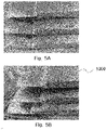
- FIG. 5A is a photograph of a rechargeable battery manufactured by the conventional method of manufacturing a rechargeable battery pouch
- FIG. 5B is a photograph of a rechargeable battery manufactured by the method of manufacturing the rechargeable battery pouch of the present disclosure.
- FIG. 5A shows that: the bent portion 210 is formed on the portion marked by the arrow, the rechargeable battery pouch is deeply recessed, and the bat-ear shaped fold is large.
- FIG. 5B shows that: the uneven portion 220 is formed in the portion marked by the arrow, the rechargeable battery pouch is slightly recessed, and the bat-ear shaped fold is small.
- the uneven portion 220 may be formed in the bent portion 210 by using the bending knife 300, thereby reducing a size of the bat-ear shaped fold and increasing the contact area between a bottom surface of the battery pouch and the cooling plate.
- FIGS. 6A and 6B each show another exemplary embodiment of the present disclosure.
- two recesses 110' may be formed in a bending die 100', and two protrusions 310' corresponding thereto may be included on a bending knife 300'.
- the pouch film 200 is disposed on the bending die 100' where the two recesses 110' are included as described above, and then pressed by the bending knife 300' having the two protrusions 310', an uneven portion 220' having two prominences and two depressions may be formed in the bent portion 210 of the pouch film 200 as shown in FIG. 6B .
- both the ends of the pouch film 200 are then rolled up. It is possible to further reduce the size of the gap between the lower end of the pouch film 200 and the electrode assembly 10, and to have two or more recesses 100 and 110' and two or more protrusions, if necessary.
- the pouch film 200 may be bent, and the uneven portions 220 and/or 220' may then be formed in the bent portion 210 by using the bending knives 300 and/or 300', thereby reducing the gap between the lower end of the pouch film 200 and the electrode assembly 10 when the electrode assembly 10 is accommodated in the pouch film 200.
- the bending knives 300 and/or 300' thereby reducing the gap between the lower end of the pouch film 200 and the electrode assembly 10 when the electrode assembly 10 is accommodated in the pouch film 200.
- the pouch film may be bent, and the uneven portion may then be formed in the bent portion by using the bending knife, thereby reducing the gap between the lower end of the pouch film and the electrode assembly when the electrode assembly is accommodated in the pouch film.
- the bending knife thereby reducing the gap between the lower end of the pouch film and the electrode assembly when the electrode assembly is accommodated in the pouch film.
- the apparatus for manufacturing the rechargeable battery pouch of the present disclosure may easily form the uneven portion in the bent portion of the pouch film by using the bending die having the recess and the bending knife disposed corresponding to the recess of the bending die to allow the pouch film to have the bent portion. In this manner, it is possible to manufacture the rechargeable battery having improved cooling performance and space efficiency.
- the rechargeable battery of the present disclosure may have the uneven portion formed in the portion where the bent portion of the pouch film is in contact with the electrode assembly, thereby reducing the size of the bat-ear shaped fold to increase the contact area between the battery pouch and the cooling plate, and improve the energy density.
Landscapes
- Chemical & Material Sciences (AREA)
- Chemical Kinetics & Catalysis (AREA)
- Electrochemistry (AREA)
- General Chemical & Material Sciences (AREA)
- Engineering & Computer Science (AREA)
- Manufacturing & Machinery (AREA)
- Mechanical Engineering (AREA)
- Secondary Cells (AREA)
- Sealing Battery Cases Or Jackets (AREA)
Abstract
Description
- This application claims priority under 35 U.S.C. §119 to
Korean Patent Application No. 10-2021-0000950, filed on Jan 5, 2021 - The following disclosure relates to a method of manufacturing a rechargeable battery pouch, an apparatus for manufacturing the same, and a rechargeable battery manufactured thereby, and more particularly, to a method of manufacturing a rechargeable battery pouch having three sealed sides, an apparatus for manufacturing the same, and a rechargeable battery manufactured thereby.
- A battery cell of a rechargeable battery may be an electrode assembly including a positive electrode, a negative electrode, a separator and an electrolyte and the battery cell may be wrapped with an exterior material. The electrode assembly may be classified into: a jelly-roll type in which a separator is interposed between sheet-type positive and negative electrodes, coated with an active material; and a stack-folding type in which stack-type unit cells, sequentially stacked on each other in a state where the separator is interposed between the plurality of positive and negative electrodes, are wound by a long-length separator film.
- The exterior material surrounding this electrode assembly may be packaged and used in a shape of a container formed into a cylinder or a cuboid by press-processing a metal material, or a pouch made of a multi-layer film formed by extruding a polymer material. Among these two types, the pouch-type battery has been widely used in various fields based on its low manufacturing cost, low weight and high formability.
- In recent years, the pouch-type rechargeable battery may be manufactured in such a manner that three sides of the electrode assembly are sealed by a pouch and at least one side of the electrode assembly is in direct contact with a cooling plate. This manufacturing manner is intended to cool the rechargeable battery, thereby increasing its energy efficiency. However, when the three sides of the rechargeable battery are sealed by the pouch, the battery cell may not be effectively cooled because the battery may have a bat-ear shaped fold occurring by interferences of wrapped portions in a process of sealing the three sides of the battery, an interference with an adjacent battery cell and/or a disturbed contact with the cooling plate.
- To address this concern in the past, performed is a process of forming the battery pouch in a certain shape to minimize the bat-ear shaped fold occurring in a center of the conventional rechargeable battery pouch. However, when manufacturing the conventional rechargeable battery pouch, the pouch may be rolled in because an elastic force accumulated in the process of forming the pouch may push the pouch upward towards the electrode assembly in the process of sealing the three sides of the rechargeable battery. In this case, the pouch may occupy a space supposed to accommodate the electrode assembly and the electrode assembly may thus have a relatively small size, which may lower energy density of the rechargeable battery. In addition, a contact area between the battery pouch and the cooling plate may be reduced due to the protruding bat-ear shaped fold, which may reduce energy efficiency of the rechargeable battery.
- One exemplary embodiment of the present disclosure is directed to providing a method of manufacturing a rechargeable battery pouch, which may suppress a bat-ear shaped fold occurring in the pouch surrounding an electrode assembly while the rechargeable battery is manufactured by using a three-side sealing method in which three edges of a folded together polymer sheet are sealed to encapsulate an electrode assembly the battery.
- Another exemplary embodiment of the present disclosure is directed to providing an apparatus for manufacturing a rechargeable battery pouch, which may suppress a bat-ear shaped fold occurring therein and a rechargeable battery manufactured thereby to have a minimal bat-ear shaped fold.
- In one general aspect, a method of manufacturing a rechargeable battery pouch includes: forming a pouch by forming a space for accommodating an electrode assembly in a pouch film; preparing a bending die used to form a bent portion in the pouch film in a direction opposite to a direction in which the pouch film is folded over in order for the pouch film to accommodate the electrode assembly; disposing the pouch film on top of the bending die; bending the pouch film by pushing down both sides of the pouch film along each side of the bending die while the pouch film is disposed on the top of the bending die; forming an uneven portion in the bent portion by pressing the bent portion, formed by the bending of the pouch film, by using a bending knife pressing into the bent portion; disposing the electrode assembly against the uneven portion of the pouch film, and folding opposing both ends of the pouch film over the electrode assembly for the space for accomodating the electrode assembly in the pouch film; and sealing together at least the folded opposing ends of the pouch film.
- The bending die may include an edge having a predetermined angle for the pouch film to be bent, and a recess may be included in the edge of the bending die.
- A protrusion corresponding to the recess of the bending die may be formed at one end of the bending knife, and when the bent portion of the pouch film is pressed by the protrusion of the bending knife in the forming of the uneven portion, the protrusion of the bending knife may be accommodated in the recess of the bending die, thereby forming the uneven portion in the pouch film.
- The bending die may have two or more recesses, and the bending knife may have two or more protrusions corresponding to the two or more recesses of the bending die.
- An apparatus for manufacturing a rechargeable battery pouch manufactured by using the method as described above includes a bending die including a) an edge having a predetermined angle for a pouch film to be bent and b) a recess formed in the edge of the bending die.
- A protrusion corresponding to the recess of the bending die may be formed at one end of a bending knife, and the protrusion of the bending knife may be accommodated in a bent portion of the pouch film, thereby forming an uneven portion in the pouch film.
- The bending die may have two or more recesses, and the bending knife may have two or more protrusions corresponding to the two or more recesses of the bending die.
- There is provided a rechargeable battery manufactured by using the method as described above, wherein the rechargeable battery pouch has three sides sealed and one side bent, and the bent portion in as a first waveform is formed on the bent one side, and the uneven portion has a second waveform of a shorter length than that of the first waveform of the bent portion is formed in a center of the bent portion.
- The uneven portion formed in a center of the bent portion may have two or more waveforms.
-
-
FIG. 1 is a flowchart showing a method of manufacturing a rechargeable battery pouch according to one embodiment of the present disclosure. -
FIGS. 2A to 2D are conceptual diagrams each schematically showing various operations of the method of manufacturing the rechargeable battery pouch of the present disclosure. -
FIG. 3 is a conceptual diagram schematically showing the inserting of an electrode assembly of the present disclosure against a pouch sheet with the pouch sheet folder to form a pouch. -
FIG. 4 is a conceptual diagram schematically showing the conventional inserting of the electrode assembly. -
FIG. 5A is a photograph of a rechargeable battery manufactured by a conventional method of manufacturing a rechargeable battery pouch; andFIG. 5B is a photograph of a rechargeable battery manufactured by the method of manufacturing a rechargeable battery pouch of the present disclosure. -
FIGS. 6A and 6B are conceptual diagrams each schematically showing the forming of an uneven portion according to another exemplary embodiment of the present disclosure. - Hereinafter, various technical aspects of the present disclosure will be described in more detail with reference to the accompanying drawings. The accompanying drawings are only examples illustrated in order to describe the technical aspects of the present disclosure in more detail. Therefore, the present disclosure is not limited to forms of the accompanying drawings.
- It should be interpreted that terms defined by a generally used dictionary have the same meanings as the meanings in the context of the related art, and these terms should not be interpreted otherwise unless the context clearly dictates. It is to be understood that when one element is referred to as being "connected to" or "coupled to" another element, it may be connected directly to or coupled directly to another element or be connected to or coupled to another element, having another element intervening therebetween.
-
FIG. 1 is a flowchart showing a method of manufacturing a rechargeable battery pouch according to one embodiment of the present disclosure. Referring toFIG. 1 , the method of manufacturing a rechargeable battery pouch of the present disclosure includes: forming a pouch (S100); preparing a bending die (S200); disposing a pouch film (S300); bending the pouch film (S400); forming an uneven portion (S500); inserting an electrode assembly (S600); and sealing the pouch (S700). - The forming of the pouch (S100) is an operation of forming the pouch which forms a space in a pouch film for accommodating an
electrode assembly 10. The inside of the pouch may be formed to be concave in a shape to match an outer shape of theelectrode assembly 10 in this operation. The formed pouch may have a shape allowing theelectrode assembly 10 to be accommodated when the pouch film is folded after inserting of the electrode assembly (S600) (which is to be performed as a subsequent operation), andpouch film 200 may be included in both of an exemplary embodiment in which an individual-type pouch film 200 is disposed and in another exemplary embodiment in which a continuous-type pouch film 200 is disposed during a roll-to-roll process of thepouch film 200. The pouch film is a strip of film that covers an electrode assembly when the electrode assembly is inserted against the pouch film and then the film is folded over forming a space inside to accommodate an electrode assembly. - The preparing of the bending die (S200) is an operation of preparing a bending die 100 used to bend the
pouch film 200 for accommodating theelectrode assembly 10. Thebending die 100 of the present disclosure may include anedge 100a having a predetermined angle for thepouch film 200 to be bent, and here, arecess 110 may be included in theedge 100a of thebending die 100. In the operation S200, thepouch film 200 may be bent to have abent portion 210 in a direction opposite to a direction in which thepouch film 200 is folded to accommodate theelectrode assembly 10. According to one embodiment of the present disclosure, when thebent portion 210 is formed on thepouch film 200 in this way, thepouch film 200 may not be pushed upwards when theelectrode assembly 10 is accommodated or otherwise inserted against thepouch film 200, and in one embodiment, the pouch film (as shown in the lower drawing ofFIG. 3 ) may be folded at an approximately right angle to fit anedge 10a of theelectrode assembly 10. - Referring to
FIGS. 2A to 2D , thebending die 100 of the present disclosure according to one exemplary embodiment may have anedge 100a formed by making a cross section of a portion where thepouch film 200 is to be folded narrow for thepouch film 200 to be bent at a predetermined angle. Here, therecess 110 may be formed in theedge 100a, and anend 300a of abending knife 300 may thus be accommodated or otherwise pushed in therecess 110 in a subsequent operation, thereby making thepouch film 200 bent. Thebending die 100 is not limited to the shape of this exemplary embodiment described with reference toFIG. 2 , and may have any of various shapes as long as thepouch film 200 may be bent at a predetermined angle. - The disposing of the pouch film (S300) is an operation of disposing the formed
pouch film 200 on top of thebending die 100, and a portion of thepouch film 200, to be bent, may be disposed on the top of therecess 110 of thebending die 100. The portion to be bent is marked by an arrow inFIG. 2A , and this arrow mark of the bent portion may be made in the forming of the pouch (S100) which occurred in a previous operation. - The bending of the pouch film (S400) is an operation of bending the
pouch film 200 disposed on the top of the bending die 100. As shown inFIG. 2B , when both sides of thepouch film 200 are pushed down while thepouch film 200 is disposed on the top of thebending die 100, thepouch film 200 may be bent along each side of thebending die 100, and thebent portion 210 in a shape of a rising peak may be formed on a center of thebent pouch film 200. The pouch film (shown inFig. 2C ) extends into the page of the drawing far enough to cover a lateral width ofelectrode assembly 10. - The forming of the uneven portion (S500) is an operation of forming the uneven part in the
bent portion 210 of thepouch film 200, formed in the bending of the pouch film (S400) which occurred in the previous operation. As shown inFIGS. 2C and 2D , therecess 110 is included in the upper edge of the bending die 100, and aprotrusion 310 corresponding to therecess 110 exists at one end of the bendingknife 300. Therefore, anuneven portion 220, i.e. uneven part formed in thebent portion 210 of thepouch film 200, may be formed as theprotrusion 310 of the bendingknife 300 is accommodated in therecess 110 of the bending die 100. - The inserting of the electrode assembly (S600) is an operation of disposing the
electrode assembly 10 against thepouch film 200 having theuneven portion 220 in its center, and bending both ends of thepouch film 200 as shown in the lower drawing ofFig. 3 in order for theelectrode assembly 10 to be accommodated in thepouch film 200. - Finally, the sealing of the pouch (S700) is an operation of sealing the ends of the
pouch film 200, that is the three sides of the folded pouch film 200 (other than its side where theuneven portion 220 is formed) may be sealed together to manufacture arechargeable battery 1000. -
FIGS. 2A to 2D are conceptual diagrams each schematically showing various operations of the method of manufacturing the rechargeable battery pouch of the present disclosure, and the method of manufacturing the rechargeable battery pouch of the present disclosure is described in more detail below with reference toFIGS. 2A to 2D. FIG. 2A shows the disposing of the pouch film (S300), and shows that the portion of thepouch film 200, to be bent, may be aligned with therecess 110 of the bending die 100. -
FIG. 2B shows the being of the pouch film (S400), and when both the sides of thepouch film 200 are pushed down, thepouch film 200 may be bent along each side of the bending die 100, and thebent portion 210 in the shape of a rising peak may be formed on the center of thepouch film 200, as shown in the drawing. -
FIGS. 2C and 2D show the forming of the uneven portion (S500). When thebent portion 210 in the shape of the rising peak is pressed by theprotrusion 310 of the bendingknife 300, the center of thepouch film 200, pressed by the bendingknife 300, may be depressed because therecess 110 is included in the upper edge of the bending die 100, and the depressed center may become theuneven portion 220. Here, theuneven portion 220 may have a waveform smaller than that of thebent portion 210. -
FIG. 3 is a conceptual diagram schematically showing the inserting of the electrode assembly (S600) of the present disclosure. As shown in an upper drawing ofFIG. 3 , thepouch film 200 of the present disclosure may have a shape convex upward and theuneven portion 220 formed in its upper portion after the forming of the uneven portion (S500), and as shown in a lower drawing ofFIG. 3 , when both the ends of thepouch film 200 are rolled up (to fold over and surround the electrode assembly 10)in a state where theelectrode assembly 10 is aligned with theuneven portion 220, theelectrode assembly 10 may be accommodated in thepouch film 200. Here, a predetermined gap E1 may be formed between a lower end of thebent pouch film 200 and theelectrode assembly 10. The method of manufacturing the rechargeable battery pouch of the present disclosure may allow the gap E1, formed in a portion where thepouch film 200 is in contact with theelectrode assembly 10, to have a reduced size as theuneven portion 220 is formed in thepouch film 200, thereby reducing a size of a bat-ear shaped fold as compared to a conventional manufacturing method. -
FIG. 4 is a conceptual diagram schematically showing the conventional inserting of the electrode assembly (S600), and according to the conventional manufacturing method, only thebent portion 210 having the shape convex upward may be formed on thebent pouch film 200. For this reason, when theelectrode assembly 10 is disposed against thepouch film 200, and both opposing ends of thepouch film 200 are then rolled up (folded together) to accommodate theelectrode assembly 10 in a space in thepouch film 200, a gap E2 is formed between the lower end of thepouch film 200 and theelectrode assembly 10 which is inevitably larger than the gap E1 formed when theuneven portion 220 is formed in thepouch film 200 according to the present disclosure. When the gap between the lower end of thepouch film 200 and theelectrode assembly 10 is increased, an unnecessary space may be formed in the pouch, resulting in reduced space efficiency. In addition, as the size of the bat-ear shaped fold is increased, the contact area between the battery pouch and the cooling plate or the like is decreased, which may impair a cooling effect. -
FIG. 5A is a photograph of a rechargeable battery manufactured by the conventional method of manufacturing a rechargeable battery pouch; andFIG. 5B is a photograph of a rechargeable battery manufactured by the method of manufacturing the rechargeable battery pouch of the present disclosure.FIG. 5A shows that: thebent portion 210 is formed on the portion marked by the arrow, the rechargeable battery pouch is deeply recessed, and the bat-ear shaped fold is large. On the contrary,FIG. 5B shows that: theuneven portion 220 is formed in the portion marked by the arrow, the rechargeable battery pouch is slightly recessed, and the bat-ear shaped fold is small. That is, when using the method of manufacturing the rechargeable battery pouch of the present disclosure, theuneven portion 220 may be formed in thebent portion 210 by using the bendingknife 300, thereby reducing a size of the bat-ear shaped fold and increasing the contact area between a bottom surface of the battery pouch and the cooling plate. -
FIGS. 6A and 6B each show another exemplary embodiment of the present disclosure. Referring toFIG. 6A , two recesses 110' may be formed in a bending die 100', and two protrusions 310' corresponding thereto may be included on a bending knife 300'. When thepouch film 200 is disposed on the bending die 100' where the two recesses 110' are included as described above, and then pressed by the bending knife 300' having the two protrusions 310', an uneven portion 220' having two prominences and two depressions may be formed in thebent portion 210 of thepouch film 200 as shown inFIG. 6B . When theelectrode assembly 10 is disposed on the uneven portion 220' having the two prominences and two depressions in the inserting of theelectrode assembly 10, and both the ends of thepouch film 200 are then rolled up. It is possible to further reduce the size of the gap between the lower end of thepouch film 200 and theelectrode assembly 10, and to have two ormore recesses 100 and 110' and two or more protrusions, if necessary. - As described above, according to the method of manufacturing the rechargeable battery pouch of the present disclosure, the
pouch film 200 may be bent, and theuneven portions 220 and/or 220' may then be formed in thebent portion 210 by using the bendingknives 300 and/or 300', thereby reducing the gap between the lower end of thepouch film 200 and theelectrode assembly 10 when theelectrode assembly 10 is accommodated in thepouch film 200. In this manner, it is possible to reduce the size of the bat-ear shaped fold to increase the contact area between the battery pouch and the cooling plate, and improve the space efficiency of the rechargeable battery. - As set forth above, according to the present disclosure, the pouch film may be bent, and the uneven portion may then be formed in the bent portion by using the bending knife, thereby reducing the gap between the lower end of the pouch film and the electrode assembly when the electrode assembly is accommodated in the pouch film. In this manner, it is possible to reduce the size of the bat-ear shaped fold to increase the contact area between the battery pouch and the cooling plate, and improve the space efficiency of the rechargeable battery.
- Further, the apparatus for manufacturing the rechargeable battery pouch of the present disclosure may easily form the uneven portion in the bent portion of the pouch film by using the bending die having the recess and the bending knife disposed corresponding to the recess of the bending die to allow the pouch film to have the bent portion. In this manner, it is possible to manufacture the rechargeable battery having improved cooling performance and space efficiency.
- Furthermore, the rechargeable battery of the present disclosure may have the uneven portion formed in the portion where the bent portion of the pouch film is in contact with the electrode assembly, thereby reducing the size of the bat-ear shaped fold to increase the contact area between the battery pouch and the cooling plate, and improve the energy density.
- The present disclosure is not limited to the abovementioned exemplary embodiments, but may be variously applied, and may be variously modified without departing from the gist of the present disclosure claimed in the claims.
Claims (9)
- A method of manufacturing a rechargeable battery pouch, the method comprising:forming a pouch by forming a space for accommodating an electrode assembly in a pouch film;preparing a bending die used to form a bent portion on the pouch film in a direction opposite to a direction in which the pouch film is folded over in order for the pouch film to accommodate the electrode assembly;disposing the pouch film on top of the bending die;bending the pouch film by pushing down both sides of the pouch film along each side of the bending die while the pouch film is disposed on the top of the bending die;forming an uneven portion in the bent portion by pressing the bent portion, formed by the bending of the pouch film, by using a bending knife pressing into the bent portion;disposing the electrode assembly against the uneven portion of the pouch film, and folding opposing ends of the pouch film over the electrode assembly for the space for accommodating the electrode assembly in the pouch film; andsealing together at least the folded opposing ends of the pouch film.
- The method of claim 1, wherein the bending die includes an edge having a predetermined angle for the pouch film to be bent, and a recess is included in the edge of the bending die.
- The method of claim 2, wherein a protrusion corresponding to the recess of the bending die is formed at one end of the bending knife, and
when the bent portion of the pouch film is pressed by the protrusion of the bending knife in the forming of the uneven portion, the protrusion of the bending knife is accommodated in the recess of the bending die, thereby forming the uneven portion in the pouch film. - The method of claim 3, wherein the bending die has two or more recesses, and the bending knife has two or more protrusions corresponding to the two or more recesses of the bending die.
- An apparatus for manufacturing a rechargeable battery pouch manufactured by using the method of claim 1, the apparatus comprising a bending die including a) an edge having a predetermined angle for a pouch film to be bent and b) a recess formed in the edge of the bending die.
- The apparatus of claim 5, wherein a protrusion corresponding to the recess of the bending die is formed at one end of a bending knife, and
the protrusion of the bending knife is accommodated in a bent portion of the pouch film, thereby forming an uneven portion in the pouch film. - The apparatus of claim 6, wherein the bending die has two or more recesses, and the bending knife has two or more protrusions corresponding to the two or more recesses of the bending die.
- A rechargeable battery manufactured by using the method of claim 1, wherein the rechargeable battery pouch has three sides sealed and one side bent, and
the bent portion in as a first waveform is formed on the bent one side, and the uneven portion has a second waveform of a shorter length than that of the first waveform of the bent portion is formed in a center of the bent portion. - The rechargeable battery of claim 8, wherein the uneven portion formed in a center of the bent portion has two or more waveforms.
Applications Claiming Priority (1)
| Application Number | Priority Date | Filing Date | Title |
|---|---|---|---|
| KR1020210000950A KR102955291B1 (en) | 2021-01-05 | 2021-01-05 | Manufacturing Method for Secondary Battery Pouch, Manufacturing Apparatus and Secondary Battery Thereof |
Publications (1)
| Publication Number | Publication Date |
|---|---|
| EP4024548A1 true EP4024548A1 (en) | 2022-07-06 |
Family
ID=80123435
Family Applications (1)
| Application Number | Title | Priority Date | Filing Date |
|---|---|---|---|
| EP22150085.3A Pending EP4024548A1 (en) | 2021-01-05 | 2022-01-03 | Method of manufacturing rechargeable battery pouch, apparatus for manufacturing the same, and rechargeable battery manufactured thereby |
Country Status (3)
| Country | Link |
|---|---|
| US (2) | US11978843B2 (en) |
| EP (1) | EP4024548A1 (en) |
| KR (1) | KR102955291B1 (en) |
Cited By (1)
| Publication number | Priority date | Publication date | Assignee | Title |
|---|---|---|---|---|
| EP4557464A1 (en) * | 2023-11-16 | 2025-05-21 | Cellforce Group GmbH | Method for shortening sealing portions |
Families Citing this family (6)
| Publication number | Priority date | Publication date | Assignee | Title |
|---|---|---|---|---|
| KR102955291B1 (en) * | 2021-01-05 | 2026-04-21 | 에스케이온 주식회사 | Manufacturing Method for Secondary Battery Pouch, Manufacturing Apparatus and Secondary Battery Thereof |
| KR102878092B1 (en) * | 2022-07-14 | 2025-10-29 | 주식회사 엠플러스 | Battery cell pouch bending unit for secondary battery packaging system with increased bending structure and pouch bending method thereby |
| EP4411944A1 (en) * | 2023-02-01 | 2024-08-07 | LG Energy Solution, Ltd. | Pouch-type battery case, secondary battery, and battery forming apparatus |
| KR102947041B1 (en) * | 2023-05-31 | 2026-04-03 | 주식회사 리베스트 | Battery and method for manufacturing battery |
| KR20250025802A (en) | 2023-08-16 | 2025-02-25 | 주식회사 엘지에너지솔루션 | Pouch-type Battery Case Pre-Folding Device and Pre-Folding Method of Pouch type Battery Case Using the Same |
| KR20250025875A (en) | 2023-08-16 | 2025-02-25 | 주식회사 엘지에너지솔루션 | Pouch-type Battery Case Folding Device and Pouch type Battery Case Foilding Method Using the Same |
Citations (3)
| Publication number | Priority date | Publication date | Assignee | Title |
|---|---|---|---|---|
| EP3321991A1 (en) * | 2015-11-03 | 2018-05-16 | LG Chem, Ltd. | Pouch cladding for secondary battery |
| EP3561899A1 (en) * | 2017-07-20 | 2019-10-30 | LG Chem, Ltd. | Secondary battery pouch sheath material, pouch-type secondary battery employing same, and method for manufacturing same |
| EP3836283A2 (en) * | 2019-09-30 | 2021-06-16 | SK Innovation Co., Ltd. | Pouch case, pouch type secondary battery and manufacturing method thereof |
Family Cites Families (10)
| Publication number | Priority date | Publication date | Assignee | Title |
|---|---|---|---|---|
| JP2006134604A (en) | 2004-11-02 | 2006-05-25 | Ngk Spark Plug Co Ltd | Method for manufacturing power storage device |
| WO2014112391A1 (en) * | 2013-01-21 | 2014-07-24 | Jfeスチール株式会社 | Method for manufacturing metal component with three-dimensional edge, and die for manufacturing |
| KR101820443B1 (en) | 2014-12-26 | 2018-01-19 | 주식회사 엘지화학 | Folding Apparatus with Improved Productivity and Method Having the Same |
| JP6659380B2 (en) * | 2016-01-29 | 2020-03-04 | 株式会社神戸製鋼所 | Method for manufacturing press-formed product and press-forming apparatus |
| KR102099907B1 (en) | 2016-03-21 | 2020-04-10 | 주식회사 엘지화학 | Battery cell and pouch sealing apparatus for sealing the battery cell |
| KR102201167B1 (en) * | 2017-04-06 | 2021-01-11 | 주식회사 엘지화학 | Battery Cell Having Recess Portion formed at Connection Portion Between Two Receiving parts |
| KR102237954B1 (en) * | 2018-03-06 | 2021-04-08 | 주식회사 엘지화학 | Manufacturing apparatus and method for pouch, manufacturing method for secondary battery |
| KR102474625B1 (en) * | 2019-03-21 | 2022-12-05 | 주식회사 엘지에너지솔루션 | Battery manufacturing device and manufacturing method of battery |
| KR102955291B1 (en) * | 2021-01-05 | 2026-04-21 | 에스케이온 주식회사 | Manufacturing Method for Secondary Battery Pouch, Manufacturing Apparatus and Secondary Battery Thereof |
| CN115642351A (en) * | 2021-07-19 | 2023-01-24 | Sk新能源株式会社 | Pouch type secondary battery and manufacturing method thereof |
-
2021
- 2021-01-05 KR KR1020210000950A patent/KR102955291B1/en active Active
-
2022
- 2022-01-03 EP EP22150085.3A patent/EP4024548A1/en active Pending
- 2022-01-04 US US17/568,243 patent/US11978843B2/en active Active
-
2024
- 2024-04-01 US US18/623,062 patent/US20240250282A1/en active Pending
Patent Citations (3)
| Publication number | Priority date | Publication date | Assignee | Title |
|---|---|---|---|---|
| EP3321991A1 (en) * | 2015-11-03 | 2018-05-16 | LG Chem, Ltd. | Pouch cladding for secondary battery |
| EP3561899A1 (en) * | 2017-07-20 | 2019-10-30 | LG Chem, Ltd. | Secondary battery pouch sheath material, pouch-type secondary battery employing same, and method for manufacturing same |
| EP3836283A2 (en) * | 2019-09-30 | 2021-06-16 | SK Innovation Co., Ltd. | Pouch case, pouch type secondary battery and manufacturing method thereof |
Cited By (2)
| Publication number | Priority date | Publication date | Assignee | Title |
|---|---|---|---|---|
| EP4557464A1 (en) * | 2023-11-16 | 2025-05-21 | Cellforce Group GmbH | Method for shortening sealing portions |
| WO2025104336A1 (en) | 2023-11-16 | 2025-05-22 | Cellforce Group Gmbh | Method for shortening seal portions |
Also Published As
| Publication number | Publication date |
|---|---|
| KR102955291B1 (en) | 2026-04-21 |
| US11978843B2 (en) | 2024-05-07 |
| US20240250282A1 (en) | 2024-07-25 |
| KR20220098990A (en) | 2022-07-12 |
| US20220216500A1 (en) | 2022-07-07 |
Similar Documents
| Publication | Publication Date | Title |
|---|---|---|
| US11978843B2 (en) | Method of manufacturing rechargeable battery pouch, apparatus for manufacturing the same, and rechargeable battery manufactured thereby | |
| US12057545B2 (en) | Pouch exterior material for secondary battery, pouch type secondary battery using the same, and method of manufacturing the same | |
| EP3699974B1 (en) | Method for manufacturing secondary battery and pouch for secondary battery | |
| KR102576860B1 (en) | Pouch case, and secondary battery and secondary battery pack using the same | |
| EP1901365B1 (en) | Battery cell with small groove at surface and battery pack including the same | |
| TWI344232B (en) | Pouch-type battery | |
| JP7396816B2 (en) | Pouch exterior material and secondary battery using the same | |
| US8034478B2 (en) | Secondary battery of improved safety | |
| US20230330900A1 (en) | Apparatus for Manufacturing Pouch of Secondary Battery | |
| EP4155045A1 (en) | Pouch, apparatus for molding pouch, and method for manufacturing secondary battery comprising pouch | |
| CN108780857B (en) | Battery cell with battery case including accommodating portion and electrode lead groove | |
| US12592437B2 (en) | Square type battery and manufacturing method of square type battery | |
| KR102115624B1 (en) | Electric storage device | |
| EP4411944A1 (en) | Pouch-type battery case, secondary battery, and battery forming apparatus | |
| US20250300279A1 (en) | Pouch-Type Battery Case and Pouch-Type Secondary Battery Including the Same, Method for Pouch-Type Battery Case, and Forming Jig for Manufacturing Pouch-Type Battery Case | |
| EP4517945A1 (en) | Pouch-type battery case, pouch-type secondary battery comprising same, method for manufacturing pouch-type battery case, and molding jig for manufacturing pouch-type battery case | |
| CN115332596B (en) | Method for producing battery cell, deep drawing tool, housing component and battery cell | |
| EP4579891A1 (en) | Secondary battery, manufacturing method for same secondary battery, and pressing device used for same manufacturing method | |
| EP4571953A1 (en) | Pouch-type battery case and forming device therefor | |
| US20230070655A1 (en) | Battery Cell and Manufacturing Device for the Same | |
| KR20240047899A (en) | Secondary battery, manufacturing method of the secondary battery, and pressing device used in the method | |
| CN120380646A (en) | Sealing apparatus and pouch type secondary battery sealed by the same |
Legal Events
| Date | Code | Title | Description |
|---|---|---|---|
| PUAI | Public reference made under article 153(3) epc to a published international application that has entered the european phase |
Free format text: ORIGINAL CODE: 0009012 |
|
| STAA | Information on the status of an ep patent application or granted ep patent |
Free format text: STATUS: REQUEST FOR EXAMINATION WAS MADE |
|
| 17P | Request for examination filed |
Effective date: 20220103 |
|
| AK | Designated contracting states |
Kind code of ref document: A1 Designated state(s): AL AT BE BG CH CY CZ DE DK EE ES FI FR GB GR HR HU IE IS IT LI LT LU LV MC MK MT NL NO PL PT RO RS SE SI SK SM TR |
|
| RAP1 | Party data changed (applicant data changed or rights of an application transferred) |
Owner name: SK ON CO., LTD. |
|
| P01 | Opt-out of the competence of the unified patent court (upc) registered |
Effective date: 20230602 |
|
| STAA | Information on the status of an ep patent application or granted ep patent |
Free format text: STATUS: EXAMINATION IS IN PROGRESS |
|
| 17Q | First examination report despatched |
Effective date: 20241223 |