EP4024376B1 - Installing and positioning method for light columns of tunnel media system - Google Patents
Installing and positioning method for light columns of tunnel media system Download PDFInfo
- Publication number
- EP4024376B1 EP4024376B1 EP21215996.6A EP21215996A EP4024376B1 EP 4024376 B1 EP4024376 B1 EP 4024376B1 EP 21215996 A EP21215996 A EP 21215996A EP 4024376 B1 EP4024376 B1 EP 4024376B1
- Authority
- EP
- European Patent Office
- Prior art keywords
- beam steel
- limiting
- plate
- steel angle
- installing
- Prior art date
- Legal status (The legal status is an assumption and is not a legal conclusion. Google has not performed a legal analysis and makes no representation as to the accuracy of the status listed.)
- Active
Links
Images




Classifications
-
- G—PHYSICS
- G09—EDUCATION; CRYPTOGRAPHY; DISPLAY; ADVERTISING; SEALS
- G09F—DISPLAYING; ADVERTISING; SIGNS; LABELS OR NAME-PLATES; SEALS
- G09F19/00—Advertising or display means not otherwise provided for
- G09F19/22—Advertising or display means on roads, walls or similar surfaces, e.g. illuminated
-
- F—MECHANICAL ENGINEERING; LIGHTING; HEATING; WEAPONS; BLASTING
- F16—ENGINEERING ELEMENTS AND UNITS; GENERAL MEASURES FOR PRODUCING AND MAINTAINING EFFECTIVE FUNCTIONING OF MACHINES OR INSTALLATIONS; THERMAL INSULATION IN GENERAL
- F16M—FRAMES, CASINGS OR BEDS OF ENGINES, MACHINES OR APPARATUS, NOT SPECIFIC TO ENGINES, MACHINES OR APPARATUS PROVIDED FOR ELSEWHERE; STANDS; SUPPORTS
- F16M11/00—Stands or trestles as supports for apparatus or articles placed thereon ; Stands for scientific apparatus such as gravitational force meters
- F16M11/42—Stands or trestles as supports for apparatus or articles placed thereon ; Stands for scientific apparatus such as gravitational force meters with arrangement for propelling the support stands on wheels
- F16M11/425—Stands or trestles as supports for apparatus or articles placed thereon ; Stands for scientific apparatus such as gravitational force meters with arrangement for propelling the support stands on wheels along guiding means
-
- F—MECHANICAL ENGINEERING; LIGHTING; HEATING; WEAPONS; BLASTING
- F16—ENGINEERING ELEMENTS AND UNITS; GENERAL MEASURES FOR PRODUCING AND MAINTAINING EFFECTIVE FUNCTIONING OF MACHINES OR INSTALLATIONS; THERMAL INSULATION IN GENERAL
- F16B—DEVICES FOR FASTENING OR SECURING CONSTRUCTIONAL ELEMENTS OR MACHINE PARTS TOGETHER, e.g. NAILS, BOLTS, CIRCLIPS, CLAMPS, CLIPS OR WEDGES; JOINTS OR JOINTING
- F16B5/00—Joining sheets or plates, e.g. panels, to one another or to strips or bars parallel to them
- F16B5/02—Joining sheets or plates, e.g. panels, to one another or to strips or bars parallel to them by means of fastening members using screw-thread
- F16B5/0216—Joining sheets or plates, e.g. panels, to one another or to strips or bars parallel to them by means of fastening members using screw-thread the position of the plates to be connected being adjustable
- F16B5/0225—Joining sheets or plates, e.g. panels, to one another or to strips or bars parallel to them by means of fastening members using screw-thread the position of the plates to be connected being adjustable allowing for adjustment parallel to the plane of the plates
-
- F—MECHANICAL ENGINEERING; LIGHTING; HEATING; WEAPONS; BLASTING
- F16—ENGINEERING ELEMENTS AND UNITS; GENERAL MEASURES FOR PRODUCING AND MAINTAINING EFFECTIVE FUNCTIONING OF MACHINES OR INSTALLATIONS; THERMAL INSULATION IN GENERAL
- F16B—DEVICES FOR FASTENING OR SECURING CONSTRUCTIONAL ELEMENTS OR MACHINE PARTS TOGETHER, e.g. NAILS, BOLTS, CIRCLIPS, CLAMPS, CLIPS OR WEDGES; JOINTS OR JOINTING
- F16B7/00—Connections of rods or tubes, e.g. of non-circular section, mutually, including resilient connections
- F16B7/18—Connections of rods or tubes, e.g. of non-circular section, mutually, including resilient connections using screw-thread elements
- F16B7/187—Connections of rods or tubes, e.g. of non-circular section, mutually, including resilient connections using screw-thread elements with sliding nuts or other additional connecting members for joining profiles provided with grooves or channels
-
- F—MECHANICAL ENGINEERING; LIGHTING; HEATING; WEAPONS; BLASTING
- F16—ENGINEERING ELEMENTS AND UNITS; GENERAL MEASURES FOR PRODUCING AND MAINTAINING EFFECTIVE FUNCTIONING OF MACHINES OR INSTALLATIONS; THERMAL INSULATION IN GENERAL
- F16M—FRAMES, CASINGS OR BEDS OF ENGINES, MACHINES OR APPARATUS, NOT SPECIFIC TO ENGINES, MACHINES OR APPARATUS PROVIDED FOR ELSEWHERE; STANDS; SUPPORTS
- F16M11/00—Stands or trestles as supports for apparatus or articles placed thereon ; Stands for scientific apparatus such as gravitational force meters
- F16M11/02—Heads
- F16M11/04—Means for attachment of apparatus; Means allowing adjustment of the apparatus relatively to the stand
-
- F—MECHANICAL ENGINEERING; LIGHTING; HEATING; WEAPONS; BLASTING
- F16—ENGINEERING ELEMENTS AND UNITS; GENERAL MEASURES FOR PRODUCING AND MAINTAINING EFFECTIVE FUNCTIONING OF MACHINES OR INSTALLATIONS; THERMAL INSULATION IN GENERAL
- F16M—FRAMES, CASINGS OR BEDS OF ENGINES, MACHINES OR APPARATUS, NOT SPECIFIC TO ENGINES, MACHINES OR APPARATUS PROVIDED FOR ELSEWHERE; STANDS; SUPPORTS
- F16M11/00—Stands or trestles as supports for apparatus or articles placed thereon ; Stands for scientific apparatus such as gravitational force meters
- F16M11/20—Undercarriages with or without wheels
- F16M11/2092—Undercarriages with or without wheels comprising means allowing depth adjustment, i.e. forward-backward translation of the head relatively to the undercarriage
-
- F—MECHANICAL ENGINEERING; LIGHTING; HEATING; WEAPONS; BLASTING
- F16—ENGINEERING ELEMENTS AND UNITS; GENERAL MEASURES FOR PRODUCING AND MAINTAINING EFFECTIVE FUNCTIONING OF MACHINES OR INSTALLATIONS; THERMAL INSULATION IN GENERAL
- F16M—FRAMES, CASINGS OR BEDS OF ENGINES, MACHINES OR APPARATUS, NOT SPECIFIC TO ENGINES, MACHINES OR APPARATUS PROVIDED FOR ELSEWHERE; STANDS; SUPPORTS
- F16M11/00—Stands or trestles as supports for apparatus or articles placed thereon ; Stands for scientific apparatus such as gravitational force meters
- F16M11/20—Undercarriages with or without wheels
- F16M11/24—Undercarriages with or without wheels changeable in height or length of legs, also for transport only, e.g. by means of tubes screwed into each other
- F16M11/242—Undercarriages with or without wheels changeable in height or length of legs, also for transport only, e.g. by means of tubes screwed into each other by spreading of the legs
- F16M11/245—Members limiting spreading of legs, e.g. "umbrella legs"
-
- F—MECHANICAL ENGINEERING; LIGHTING; HEATING; WEAPONS; BLASTING
- F16—ENGINEERING ELEMENTS AND UNITS; GENERAL MEASURES FOR PRODUCING AND MAINTAINING EFFECTIVE FUNCTIONING OF MACHINES OR INSTALLATIONS; THERMAL INSULATION IN GENERAL
- F16M—FRAMES, CASINGS OR BEDS OF ENGINES, MACHINES OR APPARATUS, NOT SPECIFIC TO ENGINES, MACHINES OR APPARATUS PROVIDED FOR ELSEWHERE; STANDS; SUPPORTS
- F16M13/00—Other supports for positioning apparatus or articles; Means for steadying hand-held apparatus or articles
- F16M13/02—Other supports for positioning apparatus or articles; Means for steadying hand-held apparatus or articles for supporting on, or attaching to, an object, e.g. tree, gate, window-frame, cycle
-
- G—PHYSICS
- G09—EDUCATION; CRYPTOGRAPHY; DISPLAY; ADVERTISING; SEALS
- G09F—DISPLAYING; ADVERTISING; SIGNS; LABELS OR NAME-PLATES; SEALS
- G09F19/00—Advertising or display means not otherwise provided for
- G09F19/12—Advertising or display means not otherwise provided for using special optical effects
-
- G—PHYSICS
- G01—MEASURING; TESTING
- G01C—MEASURING DISTANCES, LEVELS OR BEARINGS; SURVEYING; NAVIGATION; GYROSCOPIC INSTRUMENTS; PHOTOGRAMMETRY OR VIDEOGRAMMETRY
- G01C9/00—Measuring inclination, e.g. by clinometers, by levels
-
- G—PHYSICS
- G09—EDUCATION; CRYPTOGRAPHY; DISPLAY; ADVERTISING; SEALS
- G09F—DISPLAYING; ADVERTISING; SIGNS; LABELS OR NAME-PLATES; SEALS
- G09F19/00—Advertising or display means not otherwise provided for
- G09F19/22—Advertising or display means on roads, walls or similar surfaces, e.g. illuminated
- G09F2019/221—Advertising or display means on roads, walls or similar surfaces, e.g. illuminated on tunnel walls for underground trains
-
- G—PHYSICS
- G09—EDUCATION; CRYPTOGRAPHY; DISPLAY; ADVERTISING; SEALS
- G09F—DISPLAYING; ADVERTISING; SIGNS; LABELS OR NAME-PLATES; SEALS
- G09F9/00—Indicating arrangements for variable information in which the information is built-up on a support by selection or combination of individual elements
- G09F9/30—Indicating arrangements for variable information in which the information is built-up on a support by selection or combination of individual elements in which the desired character or characters are formed by combining individual elements
- G09F9/33—Indicating arrangements for variable information in which the information is built-up on a support by selection or combination of individual elements in which the desired character or characters are formed by combining individual elements being semiconductor devices, e.g. diodes
Definitions
- the present disclosure relates to a field of tunnel media system installation, and particularly relates to an installing and positioning method for light columns of a tunnel media system.
- Tunnel media also called subway tunnel video media or subway cool media
- Subway tunnel video media belong to an international leading technology.
- the media are new concept digital image media which integrate electronic display, communication and computer image engineering, human eye vision persistence is utilized, high-performance LED light columns installed on the wall face of a tunnel are remembered, and the media are researched and developed comprehensively, so that passengers can see smooth dynamic video pictures on a subway train moving at a high speed and feel unexpected visual feast.
- an adjustable support is installed on the side wall of the tunnel firstly, then an upper row of beam steel angles and a lower row of beam steel angles are installed on the adjustable support, a plurality of installation holes are formed in each beam steel angle at intervals along the length direction of the beam steel angle, the light columns are installed at the positions of beam steel angle installation holes through bolts, the upper end and the lower end of one light column are installed in the installation holes in the corresponding positions of the two beam steel angles at the same time, and then installation of the light columns can be achieved.
- the installation holes in the corresponding positions of the upper beam steel angle and the lower beam steel angle are staggered, namely the two installation holes for installing the same light column are not in the same vertical plane, the installed light columns incline, and therefore the watching effect of passengers is affected. Therefore, how to ensure that the installation holes in the corresponding positions of the upper beam steel angle and the lower beam steel angle are located in the same vertical plane and reduce the probability that the installed light columns incline is a problem to be solved.
- the present disclosure provides an installing and positioning method for light columns of a tunnel media system in order to enable installation holes in corresponding positions of two installed beam steel angles to be located in the same vertical plane and reduce the probability that the installed light columns incline.
- the installing and positioning method for light columns of a tunnel media system provided by the present disclosure adopts the following technical schemes:
- the installing and positioning method for light columns of a tunnel media system comprises the following steps:
- the upper end and the lower end of the limiting measuring tool are clamped in the installation holes of the beam steel angles, and the limiting measuring tool is perpendicular to the two beam steel angles at the same time, so that the installation holes in the two beam steel angles are located in the same vertical plane, namely the upper end and the lower end of the light column installed at the installation holes in the corresponding positions are located in the same vertical plane, and the probability that the installed light columns incline is reduced.
- the beam steel angles located at the upper part are called upper beam steel angles
- the beam steel angles located at the lower part are called lower beam steel angles
- the limiting measuring tool comprises a first limiting plate attached to the side, away from the adjustable support, of the upper beam steel angle, a second limiting plate attached to the side, away from the adjustable support, of the lower beam steel angle, and a connecting plate arranged between the first limiting plate and the second limiting plate, the side, facing the upper beam steel angle, of the first limiting plate and the side, facing the lower beam steel angle, of the second limiting plate are fixedly connected with limiting columns, the sections of the limiting columns are non-circular, and the limiting columns on the first limiting plate and the second limiting plate are respectively matched with the installation holes in the upper beam steel angle and the lower beam steel angle in an inserted mode.
- the limiting columns are non-circular, the limiting columns are inserted into the installation holes, the connecting plate can be perpendicular to the upper beam steel angle and the lower beam steel angle at the same time, and the positions of the installation holes in the upper beam steel angle and the lower beam steel angle are located in the same vertical plane, so that the installation holes in the corresponding positions of the upper beam steel angle and the lower beam steel angle are guaranteed to be located in the same vertical plane through the limiting measuring tool.
- the side, away from the connecting plate, of the first limiting plate is fixedly connected with a first clamping plate, a first positioning pin is inserted into the first clamping plate, the upper beam steel angle is located between the first positioning pin and the first limiting plate, the side, facing the connecting plate, of the second limiting plate is fixedly connected with a second clamping plate, a second positioning pin is inserted into the second clamping plate, and the lower beam steel angle is located between the second positioning pin and the second limiting plate.
- the upper beam steel angle can be clamped between the first positioning pin and the first clamping plate through the first positioning pin, so that the position of the upper beam steel angle is fixed, and the upper beam steel angle is prevented from sliding down from the limiting column under the action of external force; and the lower beam steel angle can be clamped between the second positioning pin and the second clamping plate through the second positioning pin, so that the position of the lower beam steel angle is fixed, and the lower beam steel angle is prevented from sliding down from the limiting column under the action of external force.
- S3 specifically comprises the following step: S31, determining the distance between two adjacent upper beam steel angles and the distance between two adjacent lower beam steel angles through horizontal measuring tools.
- the distance between the two adjacent upper beam steel angles and the distance between the two adjacent lower beam steel angles can be fixed through the horizontal measuring tool, and the situation that the distance between the two adjacent upper beam steel angles or the two adjacent lower beam steel angles is too large or too small, so that the overall length of the tunnel media system is affected is avoided.
- the horizontal measuring tool comprises a clamping plate which is integrally U-shaped, the clamping plate is connected to the opposite ends of two adjacent upper beam steel angles or two adjacent lower beam steel angles, and the clamping plate is provided with a fixed part for fixing the upper beam steel angle or the lower beam steel angle in the clamping plate.
- the opposite ends of the two adjacent upper beam steel angles or the two adjacent lower beam steel angles are embedded into the U-shaped openings of the clamping plates and fixed through the fixed parts, so that the two adjacent upper beam steel angles or the two adjacent lower beam steel angles can be connected together, and the connected upper beam steel angles or the connected lower beam steel angles are located on the same straight line.
- the clamping plate comprises a main plate and two side plates perpendicularly and fixedly connected to the two sides of the main plate, the fixed part comprises a clamping column arranged on the side, facing the side plate, of the main plate, and the clamping column is matched with the installation hole in an inserted mode.
- the position of the upper beam steel angle relative to the clamping plate or the position of the lower beam steel angle relative to the clamping plate can be fixed by embedding the clamping columns into the installation holes.
- the fixed part further comprises a limiting pin connected to one of the side plates in an inserted mode, and the upper beam steel angle or the lower beam steel angle is located between the limiting pin and the main plate.
- the upper beam steel angle or the lower beam steel angle can be clamped in the U-shaped groove of the clamping plate through the limiting pin, and the upper beam steel angle or the lower beam steel angle is prevented from sliding out of the U-shaped groove of the clamping plate under the action of external force.
- S3 further comprises the following step: S32, detecting the relative positions of the upper beam steel angle and the lower beam steel angle of each group through the limiting measuring tool, so that the two installation holes of the same group are located in the same vertical plane, and then fixing the positions of the upper beam steel angle and the lower beam steel angle of the group on the adjustable support.
- the upper beam steel angle and the lower beam steel angle of each group are detected by the limiting measuring tool, so that the installation holes in the corresponding positions of the upper beam steel angle and the lower beam steel angle of each group are ensured to be in the same vertical plane, and dislocation caused by installation errors is avoided.
- S3 further comprises the following step: S33, connecting two adjacent upper beam steel angles or two adjacent lower beam steel angles through assembly plates, and then taking down the horizontal measuring tools between the two adjacent upper beam steel angles or the two adjacent lower beam steel angles.
- the two adjacent upper beam steel angles and the two adjacent lower beam steel angles can be installed and connected through the assembly plate.
- S3 specifically comprises the following steps:
- the trolley is pushed to run on the track, and the level gauge runs on the track along with the trolley, so that a line with the radian consistent with that of the track is marked on the side wall of the tunnel, and a connecting line at the same position of a plurality of installed light columns is parallel to the upper surface of the track.
- the limiting tool can simulate the train running on the track, the inclination degree of the limiting tool is consistent with that of the train running on the track, the linear distances from the upper end and the lower end of the adjustable support to the limiting tool are the same by adjusting the adjustable support, and then the light columns can be parallel to the limiting tool.
- the installed light columns are parallel to the train window, and the distances between the light columns and the train window are consistent, so that the change of the angles and the distances between the light columns and the train window when the train runs on a curve road section is reduced, and after the tunnel media system is installed in the section with the curve, the program display effect is very good.
- the present disclosure has at least one of the following beneficial technical effects:
- the embodiment of the present disclosure discloses an installing and positioning method for light columns of a tunnel media system.
- the installing and positioning method for light columns of a tunnel media system comprises the following steps: S1, installing an adjustable support 5;
- S1 installing an adjustable support 5;
- the center line of the train inclines, train windows of the train and light columns 7 of the tunnel media system installed on the outer wall of a tunnel also inclined, and the angles and the distances of the light columns 7 relative to the train windows are changed, and the display effect of the light columns 7 seen by passengers in the train is seriously influenced.
- the adjustable support 5 In order to reduce the change of the angles and the distances of the light columns 7 relative to the train windows when the train runs on the curve road section, the display effect of the program is very good after the tunnel media system is installed in the section with the curve.
- the adjustable support 5 needs to be adjusted so that no matter how the train changes in inclination, the angles and distances between the sides, close to the train, of the adjustable supports 5 and the train are the same, and the angles and distances between the light columns 7 installed on the adjustable supports 5 and the train are the same.
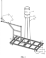
- the step of adjusting the angle of the adjustable supporting 5 when the adjustable support 5 is installed specifically comprises the following steps: S11, placing a trolley 1 on a track, installing a tripod 2 on the trolley 1, installing a level gauge 3 on the tripod 2, and installing a limiting tool 4 on the trolley 1, wherein the limiting tool 4 is perpendicular to the trolley 1.
- the tripod 2 comprises an installation clamp 21 and three legs 22 hinged to the lower side of the installation clamp 21, and the level gauge 3 can be installed on the installation clamp 21 directly.
- the specific fixed mode of the level gauge 3 and the tripod 2 in the prior art is not described in detail here.
- the trolley 1 comprises an installation rack 11 and four idler wheels 12 rotatably connected to the lower side of the installation rack 11, wherein two idler wheels 12 in a group are located at two ends of the installation rack 11 respectively, and the tripod 2 is installed on the installation rack 11.
- the two groups of idler wheels 12 are directly placed on two tracks of the train respectively, the two idler wheels 12 in the same group are placed on the same track, and then the idler wheels 12 are pulled to run on the tracks, so that the train can be simulated to run on the tracks.
- the baffle plate 121 is fixedly connected to the side, close to the other group of idler wheels 12, of each idler wheel 12 in order to prevent the idler wheels 12 from slipping off from the tracks, and when the idler wheels 12 are placed on the tracks, the baffle plate 121 also abuts against one side of the track, so that the positions of the idler wheels 12 on the tracks are fixed, and the idler wheels 12 are prevented from slipping off from the tracks during movement.
- the installation rack 11 comprises two beams 111 and a plurality of support beams 112 fixedly connected between the two beams 111, the support beams 112 are arranged at intervals along the length directions of the beams 111, a connecting beam 113 is further fixedly connected between two adjacent support beams 112, and the multiple support beams 112 can be connected through the connecting beams 113.
- Installation grooves 114 with inverted T-shaped sections are formed in the upper sides of the beams 111, the support beams 112 and the connecting beams 113, specifically, the beams 111, the support beams 112 and the connecting beams 113 can be made of aluminum profiles, and remachining of the beams 111, the support beams 112 and the connecting beams 113 can be avoided.
- the three legs 22 on the tripod 2 are directly inserted into the installation grooves 114, and meanwhile, limiting parts 13 for fixing the positions of the legs 22 in the installation grooves 114 are arranged in the installation grooves 114.
- the limiting parts 13 comprises a plurality of sliding blocks 131 slidingly connected in the installation grooves 114, two sliding blocks 131 are in a group, and the two sliding blocks 131 are located on two sides of the leg 22 for clamping the leg 22.
- Each sliding block 131 is fixedly connected with a screw 132, each screw 132 is in threaded connection with a locking nut 133, and when the locking nut 133 is unscrewed, the sliding block 131 can slide in the installation groove 114, so that the sliding block 131 is moved to any position; when the sliding blocks 131 are moved to the two sides of the legs 22, the locking nuts 133 are directly screwed, and the locking nuts 133 abut against the upper surfaces of the support beams 112 or the connecting beams 113, so that the positions of the sliding blocks 131 in the installation grooves 114 are fixed, and the positions of the legs 22 in the installation grooves 114 are fixed through the two sliding blocks 131.
- the limiting tool 4 comprises a placing rack 41 and a limiting rod 42 installed on the placing rack 41 by means of a hoop, the limiting rod 42 is perpendicular to the installation rack 11, and the limiting rod 42 also tilts when the installation rack 11 tilts due to the overheight of the outer track when the trolley 1 runs on the tracks, so that the tilting condition of the train running at the overheight position of the outer track is simulated.
- the placing rack 41 is fixed on the installation rack 11 through the limiting parts 13.
- a placing plate 43 is fixedly connected to the lower end of the placing rack 41, inserted holes 431 for the screws 132 to penetrate through are formed in the placing plate 43, the locking nuts 133 are located on the side, away from the installation frame 11, of the placing plate 43, the inserted holes 431 in the placing rack 41 are arranged on the screws 132 in a sleeving mode, then the locking nuts 133 are screwed, and then the position of the placing plate 43 can be fixed through the locking nuts 133, so that the position of the limiting tool 4 on the trolley 1 is fixed.
- the installation position of the adjustable support 5 is the position of a previously determined installation base line
- the base line is determined by adjusting the level gauge 3 to be in an oblique line mode and then pushing the trolley 1, and the trolley 1 drives the level gauge 3 to draw a line with the radian consistent with that of the track on the side wall of the tunnel, so that the determined installation base line is parallel to the upper surfaces of the tracks.
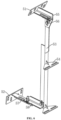
- a plurality of adjustable supports 5 are arranged at intervals along the length direction of the tunnel, the adjustable support comprises an upper foundation plate 51 used for being fixedly connected with the side wall of the tunnel, a lower foundation plate 52 used for being fixedly connected with the side wall of the tunnel and a connecting rod 53 arranged between the upper foundation plate 51 and the lower foundation plate 52, two connecting plates 54 are fixedly connected to the connecting rod 53, the two connecting plates 54 are perpendicularly and fixedly connected to the side, away from the upper foundation plate 51 and the lower foundation plate 52, of the connecting rod 53, the two connecting plates 54 are arranged at intervals along the length direction of the connecting rod 53, the two connecting plates 54 are used for being connected with the light columns 7, and the distances between the two connecting plates 54 and the limiting tool 4 are adjusted, namely, the distance between the installed light columns 7 relative to the train windows can be determined.
- a first upper connecting plate 55 is fixedly connected to the side, away from the side wall of the tunnel, of the upper foundation plate 51, a second upper connecting plate 56 is horizontally and slidably connected to one side of the first upper connecting plate 55, the upper end of the connecting rod 53 is connected with the second upper connecting plate 56, and the distance from the upper end of the connecting rod 53 to the limiting tooling 4 (referring to FIG. 2 ) can be adjusted by sliding the position of the second upper connecting plate 56 on the first upper connecting plate 55.
- a first waist-shaped hole 551 is formed in the first upper connecting plate 55, the length direction of the first waist-shaped hole 551 is consistent with the length of a straight line between the side wall of the tunnel and the limiting tool 4, a first installation hole 561 is formed in the second upper connecting plate 56, a first adjusting bolt 591 is installed in the first waist-shaped hole 551 and the first installation hole 561, the first adjusting bolt 591 is in threaded connection with a first adjusting nut 592, and the positions of the first upper connecting plate 55 and the second upper connecting plate 56 can be fixed through the first adjusting bolt 591 and the first adjusting nut 592.
- the first adjusting bolt 591 When the first adjusting bolt 591 is operated to slide in the first waist-shaped hole 551, the first adjusting bolt 591 can drive the second upper connecting plate 56 to slide in the first waist-shaped hole 551 through the side wall of the first installation hole 561, and therefore horizontal sliding fit between the second upper connecting plate 56 and the first upper connecting plate 55 is achieved.
- a first lower connecting plate 57 is fixedly connected to the side, away from the side wall of the tunnel, of the lower foundation plate 52, a second lower connecting plate 58 is horizontally and slidably connected to one side of the first lower connecting plate 57, the lower end of the connecting rod 53 is connected with the second lower connecting plate 58, and by sliding the position of the second lower connecting plate 58 on the first lower connecting plate 57, the lower end of the connecting rod 53 can be driven to move along the length direction of the first lower connecting plate 57, and therefore the distance between the lower end of the connecting rod 53 and the limiting tool 4 is adjusted.
- a second waist-shaped hole 571 is formed in the first lower connecting plate 57
- a second installation hole 581 is formed in the second lower connecting plate 58
- a second adjusting bolt 593 is installed in the second waist-shaped hole 571 and the second installation hole 581
- the second adjusting bolt 593 is in threaded connection with a second adjusting nut 594.
- the position of the second lower connecting plate 58 on the first lower connecting plate 57 can be fixed through the second adjusting bolt 593 and the second adjusting nut 594, meanwhile, the second adjusting bolt 593 is operated to slide in the second waist-shaped hole 571, the second adjusting bolt 593 drives the second lower connecting plate 58 to slide along the length direction of the second wait-shaped hole 571 through the hole wall of the second installation hole 581, and therefore, horizontal sliding fit between the second lower connecting plate 58 and the first lower connecting plate 57 is achieved.
- the distance between the connecting rod 53 and the limiting tool 4 can be adjusted, so that the distances between the two connecting plates 54 perpendicularly and fixedly connected to the connecting rod 53 and the limiting tool 4 are the same.
- the upper end and the lower end of the connecting rod 53 are in vertical sliding fit with the second upper connecting plate 56 and the second lower connecting plate 58 respectively, the height of the connecting plate 54 fixedly connected to the connecting rod 53 can be adjusted by operating the upper end and the lower end of the connecting rod 53 to perpendicularly slide on the second upper connecting plate 56 and the second lower connecting plate 58, and therefore the heights of the light columns 7 installed on the connecting plate 54 are adjusted.
- a vertical third waist-shaped hole 562 is formed in the second upper connecting plate 56
- a third installation hole 531 is formed in the upper end of the connecting rod 53
- a third adjusting bolt 595 is installed in the third waist-shaped hole 562 and the third installation hole 531
- the third adjusting bolt 595 is in threaded connection with a third adjusting nut 596
- the position between the connecting rod 53 and the second upper connecting plate 56 can be fixed through the third adjusting bolt 595 and the third adjusting nut 596
- the height of the upper end of the connecting rod 53 can be adjusted by operating the third adjusting bolt 595 to slide in the third waist-shaped hole 562.
- a fourth installation hole 582 is formed in the second lower connecting plate 58, a vertical fourth waist-shaped hole 532 is formed in the lower end of the connecting rod 53, a fourth adjusting bolt 597 is installed in the fourth waist-shaped hole 532 and the fourth installation hole 582, the fourth adjusting bolt 597 is in bolted connection with a fourth adjusting nut 598, the position between the lower end of the connecting rod 53 and the second lower connecting plate 58 can be fixed through the fourth adjusting bolt 597 and the fourth adjusting nut 598, and the height of the lower end of the connecting rod 53 can be adjusted by operating the fourth adjusting bolt 597 to slide in the fourth waist-shaped hole 532.
- the upper end of the connecting rod 53 also rotates around the third adjusting bolt 595, and the lower end of the connecting rod 53 also rotates around the fourth adjusting bolt 597, so that the inclination degree of the connecting rod 53 is adjusted, and the connecting rod 53 is parallel to the limiting tool 4, namely, the light columns installed on the two connecting plates 54 are parallel to the train windows.
- the positions of the first adjusting bolt 591 in the middle of the first waist-shaped hole 551 and the second adjusting bolt 593 in the middle of the second waist-shaped hole 571 are adjusted in advance, then the positions of the third adjusting bolt 595 in the middle of the third waist-shaped hole 562 and the fourth adjusting bolt 597 in the middle of the fourth waist-shaped hole 532 are adjusted, then the upper foundation plate 51 and the lower foundation plate 52 are installed and fixed, and the first adjusting bolt 591, the second adjusting bolt 593, the third adjusting bolt 595 and the fourth adjusting bolt 597 are all adjusted to the middle positions, so that the installed adjustable supports 5 can be correspondingly and accurately adjusted subsequently.
- the level gauge 3 When the level gauge 3 is adjusted, the level gauge 3 is adjusted in an oblique line mode.
- the level gauge 3 is in a straight line mode, on the premise that the relative height of the level gauge 3 is not changed, the horizontal lines emitted by the level gauge 3 within 3 degrees of the inclination angle are completely overlapped.
- the inclination angle exceeds 3 degrees, relative positions of the laser rays emitted by the level gauge 3 are linearly lifted or lowered. Therefore, when the level gauge 3 is used in a straight line mode, certain errors are generated.
- the laser rays emitted by the level gauge 3 changes correspondingly, so that the radians of the laser rays emitted by the level gauge 3 are consistent with those of the tracks. Therefore, when the tracks change little, the laser rays emitted by the level gauge 3 do not change, and errors between the emitted laser rays and the radians of the tracks can be avoided.
- the present disclosure discloses a method for adjusting the oblique line mode of a Leocel LS639 type level gauge 3 by taking the Leocel LS639 type level gauge 3 as an example, firstly, when a bubble in the level gauge 3 is adjusted to be in the middle position, a switch of the level gauge 3 is turned on, three keys of V1, V2and H on the level gauge 3 are pressed, the height of the tripod 2 is adjusted to a required installation height, and in the disclosure, the laser lines are adjusted to hit at the center position of the connecting plate 54 at the upper part of the connecting rod 53.
- the switch of the level gauge 3 is turned off, the key of oblique line mode on the level gauge 3 is pressed down, and the three keys of V1, V2 and H of the level gauge 3 are pressed down again.
- another red "+” appears on the connecting plate 54 at the upper part of the connecting rod 53; next, any two legs of the tripod 2 are adjusted so that the center of the cross laser rays emitted by infrared rays of the level gauge 3 is located at the center of the connecting plate 54 at the upper part of the connecting rod 53, which is the installation height in the oblique line mode.
- the level gauge 3 is driven by the trolley 1 to run on the tracks, and the level gauge 3 can draw a line parallel to the upper surfaces of the tracks, so that the adjustable support 5 can be conveniently positioned during installation.
- the centers of the laser rays emitted by the level gauge 3 are located at the center of the connecting plate 54 located at the upper end of the connecting rod 53 by adjusting the height of the connecting rod 53, and meanwhile a first mark and a second mark are made on the limiting tool 4 through a marking pen or adhesive tape and the like, and then the linear distance between the two connecting plates 54 to the limiting rod 42, namely, the distance between the connecting plate 54 located at the upper end of the connecting rod 53 and the first marking, and the distance between the connecting plate 54 located at the lower end of the connecting rod 53 and the second mark, are measured by a box ruler.
- the first adjusting bolt 591 is adjusted to slide in the first waist-shaped hole 551, and the second adjusting bolt 593 is adjusted to slide in the second waist-shaped hole 571, so that the distances between the two connecting plates 54 and the limiting rod 42 are consistent, and at the moment, the first adjusting bolt 591, the second adjusting bolt 593, the third adjusting bolt 595 and the fourth adjusting bolt 597 are locked, so that the installation of the adjustable bracket 5 can be completed.
- the adjustable supports 5 When each adjustable support 5 is installed, the adjustable supports 5 need to be installed on an installation base line determined in the earlier stage, the connecting rod 53 is adjusted so that the laser rays emitted by the level gauge 3 are located in the middle of the connecting plate 54 located at the upper end of the connecting rod 53, then the distance between one connecting plate 54 located at the upper end of the connecting rod 53 and the first mark and the distance between the other connecting plate 54 at the lower end of the connecting rod 53 and the second mark are measured through the box ruler, by adjusting the position of the first adjusting bolt 591 in the first waist-shaped hole 551 and the position of the second adjusting bolt 593 in the second waist-shaped hole 571, the distances between the two connecting plates 54 on each adjustable support 5 and the limiting rod 42 are equal, and therefore, each installed light column 7 is parallel to the train window of the train, and the distances between the light columns 7 and the train windows are equal.
- the section of the beam steel angle 6 is in an L shape
- the beam steel angle 6 comprises a connecting part 61 fixedly connected with the connecting plate 54 and a fixed part 62 perpendicularly and fixedly connected to the side, away from the connecting rod 53, of the connecting part 61
- the connecting part 61 is placed on the connecting plate 54 and attached to the upper surface of the connecting plate 54
- the connecting part 61 and the connecting plate 54 are fixedly connected through fixed bolts
- the fixed part 62 is used for being connected with the light column 7 so as to fix the position of the light column 7.
- installation holes 63 connected with the light columns 7 are formed in the fixed part 62 of each beam steel angle 6 at intervals along the length direction of the fixed part 62.
- the two beam steel angles 6 in the same group comprise an upper beam steel angle 64 installed the connecting plate 54 at the upper part of the connecting rod 53 and a lower beam steel angle 65 installed on the connecting plate 54 at the lower part of the connecting rod 53.
- the two beam steel angles 6 in the same group are installed firstly, the upper beam steel angle 64 is installed on the connecting plate 54 at the upper part of the adjustable support 5, then the lower beam steel angle 65 is placed on the connecting plate 54 at the lower part of the adjustable support 5, then the upper end and the lower end of the limiting measuring tool 8 are clamped in the installation holes 63 in the corresponding positions of the upper beam steel angle 64 and the lower beam steel angle 65 respectively, the limiting measuring tool 8 is perpendicular to the two beam steel angles 6 at the same time, and finally the position of the lower beam steel angle 65 on the adjustable support 5 is fixed; the position between the upper beam steel angle 64 and the lower beam steel angle 65 in the same group can be fixed through the limiting measuring tool 8, so that the installation holes 63 in the corresponding positions of the upper beam steel angle
- the limiting measuring tool 8 comprises a first limiting plate 81 attached to the side, away from the connecting rod 53, of the upper beam steel angle 64, a second limiting plate 82 attached to the side, away from the connecting rod 53, of the lower beam steel angle 65, and a connecting plate 83 arranged between the first limiting plate 81 and the second limiting plate 82.
- the side, facing the upper beam steel angle 64, of the first limiting plate 81 and the side, facing the lower beam steel angle 65, of the second limiting plate 82 are fixedly connected with limiting columns 84, wherein the sections of the limiting columns 84 are non-circular, and the limiting columns 84 on the first limiting plate 81 and the second limiting plate 82 are respectively matched with the installation holes 63 in the upper beam steel angle 64 and the lower beam steel angle 65 in an inserted mode.
- the section of the limiting column 84 can be rectangular, oval, rhombic or in other irregular shapes, so long as the limiting column 84 is inserted into the installation hole 63, the limiting column 84 can be matched with the installation hole 63 in an inserted mode, and the limiting column 84 can be prevented from rotating in the installation hole 63, so that the upper beam steel angle 64 and the lower beam steel angle 65 are both perpendicular to the limiting measuring tool 8.
- the section of the limiting column 84 is rectangular.
- the connecting plate 83 When in use, the connecting plate 83 is directly operated to insert the two limiting columns 84 into the installation holes 63 in the upper beam steel angle 64 and the lower beam steel angle 65, and the connecting plate 83 is perpendicular to the upper beam steel angle 64 and the lower beam steel angle 65 at the same time, so that the installation holes 63 in the corresponding positions of the upper beam steel angle 64 and the lower beam steel angle 65 are located in the same vertical plane.
- the limiting column 84 comprises a rectangular clamping column 841, a screw 842 fixedly connected to one end of the clamping column 841, a clamping ring 844 fixedly connected to the outer wall of the clamping column 841 and a nut 843 in threaded connection to the screw 842, wherein the clamping ring 844 is located at the end, close to the screw 842, of the clamping column 841, the circumference of the clamping ring 844 is larger than that of the screw 842, and first clamping grooves 891 for embedding the screws 842 are formed in the first limiting plate 81 and the second limiting plate 82.
- the position of the limiting column 84 on the first limiting plate 81 or the second limiting plate 82 is fixed, when the limiting column 84 needs to be disassembled, the nut 843 is directly screwed down from the screw 842, and detachable connection of the limiting column 84 is achieved. Due to the detachable connection of the limiting column 84, the limiting column 84 can be detached and replaced as required to meet the requirements of the installation holes 63 with different shapes and sizes, and the disclosure range is wider.
- the side, facing the connecting plate 83, of the first limiting plate 81 is perpendicularly and fixedly connected with a first auxiliary plate 85, and the first auxiliary plate 85 is located on the side, away from the limiting column 84, of the first limiting plate 81; and the side, facing the connecting plate 83, of the second limiting plate 82 is perpendicularly and fixedly connected with a second auxiliary plate 86, and the second auxiliary plate 86 is located on the side, away from the limiting column 84, of the first limiting plate 81.
- the connecting plate 83 is perpendicularly and fixedly connected between the first auxiliary plate 85 and the second auxiliary plate 86, the connecting plate 83 can be operated to drive the limiting columns 84 located on the first limiting plate 81 and the second limiting plate 82 to be inserted into the installation holes 63 through the first auxiliary plate 85 and the second auxiliary plate 86, and limitation of the upper beam steel angle 64 and the lower beam steel angle 65 is achieved.
- the relative position between the upper beam steel angle 64 and the lower beam steel angle 65 is changed.
- the side, away from the connecting plate 83, of the first limiting plate 81 is perpendicularly and fixedly connected with a first clamping plate 87, the first clamping plate 87 is located on the side, facing the limiting column 84, of the first limiting plate 81, a first positioning pin 871 is inserted into the first clamping plate 87 in a matched mode, the first positioning pin 871 is located on the side, away from the first limiting plate 81, of the upper beam steel angle 64, the upper beam steel angle 64 can be clamped between the first positioning pin 871 and the first limiting plate 81 through the first positioning pin 871, so that the position between the upper beam steel angle 64 and the first limiting plate 81 is fixed.
- the side, away from the connecting plate 83, of the second limiting plate 82 is perpendicularly and fixedly connected with a second clamping plate 88, the second clamping plate 88 is located on the side, facing the limiting column 84, of the second limiting plate 82, a second positioning pin 881 is inserted into the second clamping plate 88 in a matched mode, the second positioning pin 881 is located on the side, away from the second limiting plate 88, of the lower beam steel angle 65, the lower beam steel angle 65 can be clamped between the second positioning pin 881 and the second limiting plate 82 through the second positioning pin 881, so that the position between the lower beam steel angle 65 and the second limiting plate 82 is fixed.
- the first positioning pin 871 is directly inserted into the first clamping plate 87
- the second positioning pin 881 is directly inserted into the second clamping plate 88
- the positions of the limiting measuring tool 8 and the upper beam steel angle 64 and the positions of the limiting measuring tool 8 and the lower beam steel angle 65 can be fixed, so that the installation holes 63 in the corresponding positions of the upper beam steel angle 64 and the lower beam steel angle 65 are located in the same vertical plane, the two ends of the light columns 7 installed on the upper beam steel angle 64 and the lower beam steel angle 65 are ensured to be in a vertical state, and the probability that the installed light columns 7 incline is greatly reduced.
- the number of the limiting columns 84 located on the first limiting plate 81 is two, the direction of a connecting line between the two limiting columns 84 is perpendicular to the length direction of the connecting plate 83, and the two limiting columns 84 are matched with the two installation holes 63 in the upper beam steel angle 64 in an inserted mode respectively, so that limitation of the upper beam steel angle 64 is more accurate, and relative movement of the upper beam steel angle 64 is avoided.
- the number of the limiting columns 84 located on the second limiting plate 82 is two, the direction of a connecting line between the two limiting columns 84 is perpendicular to the length direction of the connecting plate 83, and the two limiting columns 84 are matched with the two installation holes 63 in the lower beam steel angle 65 in an inserted mode respectively, so that limitation of the lower beam steel angle 65 is more accurate through the two limiting columns 84, and relative movement of the lower beam steel angle 65 is avoided.
- the distance between the installed upper beam steel angle 64 and the installed lower beam steel angle 65 may generate certain errors, so that the limiting column 84 located on the first limiting plate 81 and the limiting column 84 located on the second limiting plate 82 cannot be inserted into the installation holes 63 in the upper beam steel angle 64 and the lower beam steel angle 65 at the same time.
- two second clamping grooves 892 communicating with the first clamping grooves 891 are formed in the second limiting plate 82, and the two second clamping grooves 892 communicate with the two first clamping grooves 891 respectively, so that each first clamping groove 891 and the second clamping groove 892 communicating with the first clamping groove 891 jointly form a waist-shaped hole consistent with the connecting plate 83 in length, and the two limiting columns 84 located on the second limiting plate 82 can slide in the two waist-shaped holes, so that a certain activity space is provided.
- the limiting column 84 on the second limiting plate 82 can be operated to slide in the waist-shaped hole until the limiting column 84 is inserted into the installation hole 63 in the lower beam steel angle 65, and positioning of the upper beam steel angle 64 and the lower beam steel angle 65 is achieved.
- an operating panel 845 is arranged between the two limiting columns 84 located on the second limiting plate 82, the operating panel 845 is arranged on the screws 842 of the two limiting columns 84 in a sleeving mode, and the operating panel 845 is located between the nut 843 and the second limiting plate 82.
- a worker can drive the two limiting columns 84 to slide in the two waist-shaped holes respectively at the same time by directly applying force to the operating plate 845, and the operation is more convenient.
- the two screws 842 located on the second limiting plate 82 are sleeved with gaskets 846, and the gaskets 846 are located between the second limiting plate 82 and the operating panel 845, so that a certain gap is reserved between the operating panel 845 and the second limiting plate 82, and the operation is more convenient and labor-saving.
- the operating panel 845 is in threaded connection with an abutting screw 847, and the abutting screw 847 can abut against the side, away from the clamping ring 844, of the second limiting plate 82, so that the second limiting plate 82 is clamped between the abutting screw 847 and the clamping ring 844, and the position of the operating panel 845 relative to the second limiting plate 82 is fixed.
- the rest of beam steel angles 6 need to be installed in sequence, and as the installation length of the tunnel media system is fixed, when two adjacent upper beam steel angles 64 and two adjacent lower beam steel angles 65 are connected through bolts, due to the fact that the difference between the diameter of the bolt and the diameter of the threaded hole is generally 2 mm, a certain error exists between the upper beam steel angle 64 or the lower beam steel angle 65 after installation, when the error is accumulated to a certain value, the overall length of the tunnel media system can be affected, and meanwhile, when the errors of the upper beam steel angle 64 and the lower beam steel angle 65 are inconsistent, the light columns 7 installed in the corresponding installation holes 63 can incline.
- the two adjacent upper beam steel angles 64 or two adjacent lower beam steel angles 65 need to be installed by means of the horizontal measuring tools 9, and the distance between two adjacent upper beam steel angles 64 and two adjacent lower beam steel angles 65 can be fixed through the horizontal measuring tools 9.
- the horizontal measuring tool 9 comprises a clamping plate 91 and a fixed part 92, wherein the clamping plate 91 is integrally U-shaped, opposite ends of two adjacent upper beam steel angles 64 or two adjacent lower beam steel angles 65 can be embedded into the clamping plate 91, the fixed part 92 is used for fixing the positions of the upper beam steel angles 64 or the lower beam steel angles 65 in the clamping plate 91, and the fixed part 92 is located in a U-shaped opening of the clamping plate 91.
- the opposite ends of the two adjacent upper beam steel angles 64 or the two adjacent lower beam steel angles 65 are directly placed in the U-shaped openings of the clamping plates 91, and then the positions of the two upper beam steel angles 64 or the two lower beam steel angles 65 in the clamping plate 91 are fixed through the fixed part 92.
- the clamping plate 91 comprises a main plate 911 and two side plates 912 perpendicularly and fixedly connected to the two sides of the main plate 911
- the fixed part 92 comprises two clamping columns 921 fixedly connected to the sides, facing the two side plates 912, of the main plate 911
- the section of the clamping column 921 is consistent with the installation hole 63 in shape and are rectangula
- the clamping columns 921 are matched with the installation holes 63 in an inserted mode and cannot shake in the installation holes 63.
- two adjacent upper beam steel angles 64 or two adjacent lower beam steel angles 65 are directly placed in the U-shaped openings of the clamping plates 91, and the two clamping columns 921 are inserted into the installation holes 63 in the two adjacent upper beam steel angles 64 or the two adjacent lower beam steel angles 65 respectively. Due to the fact that the clamping column 921 cannot slide in the installation hole 63, the relative position between two adjacent upper beam steel angles 64 or two adjacent lower beam steel angles 65 can be fixed.
- a limiting pin 922 is inserted into one side plate 912 in a matched mode and located on the side, away from the main plate 911, of the upper beam steel angle 64 or the lower beam steel angle 65, and the upper beam steel angle 64 or the lower beam steel angle 65 can be fixed between the limiting pin 922 and the main plate 911 through the limiting pin 922, so that the positions of the upper beam steel angle 64 and the lower beam steel angle 65 are fixed.
- the assembly plate 94 is plate-shaped, at least two assembly holes 941 are formed in the assembly plate 94, and the two assembly holes 941 correspond to the installation holes 63 in the opposite ends of the two adjacent upper beam steel angles 64 or the two adjacent lower beam steel angles 65 respectively.
- four assembly holes 941 are taken as an example, two installation holes 63 formed in the end part of each upper cross beam steel angle 64 or lower cross beam steel angle 65 correspond to the assembly holes 941.
- a connecting bolt 95 is arranged in the assembly hole 941 in a penetrating mode, and a connecting nut 96 is connected to the connecting bolt 95 in a threaded mode.
- the connecting bolts 95 penetrate through the installation holes 63 and the assembly holes 941 in the end parts of the upper beam steel angles 64 or the lower beam steel angles 65 at the same time, so that the assembly plate 94 can be connected with the two adjacent upper beam steel angles 64 or the assembly plate 94 can be connected with the two adjacent lower beam steel angles 65 through the connecting bolts 95 and the connecting nuts 96.
- an avoiding groove 93 for embedding the assembly plate 94 is formed in one side of the clamping plate 91, and the avoiding groove 93 is formed in the middle of one side plate 912 where the limiting pin 922 is inserted and the main plate 911 at the same time.
- the assembly plate 94 is directly placed at the joint of the two upper beam steel angles 64 or the two lower beam steel angles 65 from the avoiding groove 93, and the two upper beam steel angles 64 and the assembly plate 94 or the two lower beam steel angles 65 and the assembly plate 94 are connected together through the connecting bolts 95. Therefore, the relative position between two adjacent upper beam steel angles 64 or two adjacent lower beam steel angles 65 can be fixed, and then the horizontal measuring tools 9 are taken down. Circulation is conducted in sequence until all the adjustable supports 5 are installed completely.
- the implementation principle of the installing and positioning method for light columns of a tunnel media system is that the relative position relation between the upper beam steel angles 64 and the lower beam steel angles 65 can be fixed through the limiting measuring tools 8, so that the installation holes 63 in the upper beam steel angle 64 and the lower beam steel angle 65 in the same group are located in the same vertical plane, and the probability that the installed light columns 7 incline is reduced.
- the relative position between two adjacent upper beam steel angles 64 or two adjacent lower beam steel angles 65 can be fixed through the horizontal measuring tools 9, errors caused by connection of the two steel angles are reduced, and it is guaranteed that the length of the installed upper beam steel angles 64 or the installed lower beam steel angle 65 is consistent with that of the tunnel media system, and then the installation holes 63 in the corresponding positions of the upper beam steel angle 64 and the lower beam steel angle 65 of each group are in the same vertical plane, the upper beam steel angle 64 and the lower beam steel angle 65 of each group are detected through the limiting measuring tool 8, the two ends of each installed light column 7 are located in the same plane, and the probability that the installed light columns 7 incline is greatly reduced.
- the distances between the adjustable supports 5 and the limiting tool 4 are adjusted to be consistent, and the inclination degree of the adjustable support 5 is consistent with that of the limiting tool, so that the distances between the light columns 7 installed on the adjustable support 5 and the train window are consistent, and the inclination degree of the adjustable support 5 is consistent with that of the train, so that the video animation played by the installed tunnel media system is attached to the train window, and the display effect is better.
Landscapes
- Engineering & Computer Science (AREA)
- General Engineering & Computer Science (AREA)
- Mechanical Engineering (AREA)
- Business, Economics & Management (AREA)
- Accounting & Taxation (AREA)
- Marketing (AREA)
- Physics & Mathematics (AREA)
- General Physics & Mathematics (AREA)
- Theoretical Computer Science (AREA)
- Length Measuring Devices By Optical Means (AREA)
- Conveying And Assembling Of Building Elements In Situ (AREA)
Description
- The present disclosure relates to a field of tunnel media system installation, and particularly relates to an installing and positioning method for light columns of a tunnel media system.
- Tunnel media, also called subway tunnel video media or subway cool media, are emerging high-tech advertising media. Subway tunnel video media belong to an international leading technology. The media are new concept digital image media which integrate electronic display, communication and computer image engineering, human eye vision persistence is utilized, high-performance LED light columns installed on the wall face of a tunnel are remembered, and the media are researched and developed comprehensively, so that passengers can see smooth dynamic video pictures on a subway train moving at a high speed and feel unexpected visual feast.
- At present, when light columns of a tunnel media system are installed, an adjustable support is installed on the side wall of the tunnel firstly, then an upper row of beam steel angles and a lower row of beam steel angles are installed on the adjustable support, a plurality of installation holes are formed in each beam steel angle at intervals along the length direction of the beam steel angle, the light columns are installed at the positions of beam steel angle installation holes through bolts, the upper end and the lower end of one light column are installed in the installation holes in the corresponding positions of the two beam steel angles at the same time, and then installation of the light columns can be achieved. However, when the beam steel angles are fixedly connected to the adjustable support, if the installation holes in the corresponding positions of the upper beam steel angle and the lower beam steel angle are staggered, namely the two installation holes for installing the same light column are not in the same vertical plane, the installed light columns incline, and therefore the watching effect of passengers is affected. Therefore, how to ensure that the installation holes in the corresponding positions of the upper beam steel angle and the lower beam steel angle are located in the same vertical plane and reduce the probability that the installed light columns incline is a problem to be solved.
- The present disclosure provides an installing and positioning method for light columns of a tunnel media system in order to enable installation holes in corresponding positions of two installed beam steel angles to be located in the same vertical plane and reduce the probability that the installed light columns incline.
- The installing and positioning method for light columns of a tunnel media system provided by the present disclosure adopts the following technical schemes:
- The installing and positioning method for light columns of a tunnel media system comprises the following steps:
- S1, installing an
adjustable support 5; - S2, installing a first group of beam steel angles, comprising following steps: forming installation holes in each beam steel angle at intervals along the length direction of each beam steel angle, firstly installing a first beam steel angle, called an upper beam steel angle, on a connecting plate on the upper side of the adjustable support, then installing a second beam steel angle, called a lower beam steel angle, on a connecting plate on the lower side of the adjustable support, and clamping the upper ends and the lower ends of a limiting measuring tool in the installation holes in the corresponding positions of the upper and lower beam steel angles respectively in which the limiting measuring tool is perpendicular to the two beam steel angles at the same time, and finally fixing the position of the beam steel angle located on the connecting plate on the lower side on the adjustable support; the limiting measuring tool comprises a first limiting plate attached to a side, away from the adjustable support, of the upper beam steel angle, a second limiting plate attached to a side, away from the adjustable support, of the lower beam steel angle, and a connecting plate arranged between the first limiting plate and the second limiting plate, a side, facing the upper beam steel angle, of the first limiting plate and a side, facing the lower beam steel angle, of the second limiting plate are fixedly connected with limiting columns, sections of the limiting columns are non-circular, and the limiting columns on the first limiting plate and the second limiting plate are respectively matched with the installation holes in the upper beam steel angle and the lower beam steel angle in an inserted mode; and a side, away from the connecting plate of the limiting measuring tool, of the first limiting plate is fixedly connected with a first clamping plate, a first positioning pin is inserted into the first clamping plate, the upper beam steel angle is located between the first positioning pin and the first limiting plate, a side, facing the connecting plate of the limiting measuring tool, of the second limiting plate is fixedly connected with a second clamping plate, a second positioning pin is inserted into the second clamping plate, and the lower beam steel angle is located between the second positioning pin and the second limiting plate;
- S3, sequentially installing, side by side along the length direction of the tunnel media system, the rest of the groups of beam steel angles on the adjustable support in a likewise manner as shown in S2; and
- S4, installing the light columns at the installation holes at the corresponding positions of the upper and lower beam steel angles.
- By adopting the technical scheme, the upper end and the lower end of the limiting measuring tool are clamped in the installation holes of the beam steel angles, and the limiting measuring tool is perpendicular to the two beam steel angles at the same time, so that the installation holes in the two beam steel angles are located in the same vertical plane, namely the upper end and the lower end of the light column installed at the installation holes in the corresponding positions are located in the same vertical plane, and the probability that the installed light columns incline is reduced.
- Optionally, the beam steel angles located at the upper part are called upper beam steel angles, the beam steel angles located at the lower part are called lower beam steel angles, the limiting measuring tool comprises a first limiting plate attached to the side, away from the adjustable support, of the upper beam steel angle, a second limiting plate attached to the side, away from the adjustable support, of the lower beam steel angle, and a connecting plate arranged between the first limiting plate and the second limiting plate, the side, facing the upper beam steel angle, of the first limiting plate and the side, facing the lower beam steel angle, of the second limiting plate are fixedly connected with limiting columns, the sections of the limiting columns are non-circular, and the limiting columns on the first limiting plate and the second limiting plate are respectively matched with the installation holes in the upper beam steel angle and the lower beam steel angle in an inserted mode.
- By adopting the technical scheme, the limiting columns are non-circular, the limiting columns are inserted into the installation holes, the connecting plate can be perpendicular to the upper beam steel angle and the lower beam steel angle at the same time, and the positions of the installation holes in the upper beam steel angle and the lower beam steel angle are located in the same vertical plane, so that the installation holes in the corresponding positions of the upper beam steel angle and the lower beam steel angle are guaranteed to be located in the same vertical plane through the limiting measuring tool.
- Optionally, the side, away from the connecting plate, of the first limiting plate is fixedly connected with a first clamping plate, a first positioning pin is inserted into the first clamping plate, the upper beam steel angle is located between the first positioning pin and the first limiting plate, the side, facing the connecting plate, of the second limiting plate is fixedly connected with a second clamping plate, a second positioning pin is inserted into the second clamping plate, and the lower beam steel angle is located between the second positioning pin and the second limiting plate.
- By adopting the technical scheme, the upper beam steel angle can be clamped between the first positioning pin and the first clamping plate through the first positioning pin, so that the position of the upper beam steel angle is fixed, and the upper beam steel angle is prevented from sliding down from the limiting column under the action of external force; and the lower beam steel angle can be clamped between the second positioning pin and the second clamping plate through the second positioning pin, so that the position of the lower beam steel angle is fixed, and the lower beam steel angle is prevented from sliding down from the limiting column under the action of external force.
- Optionally, S3 specifically comprises the following step:
S31, determining the distance between two adjacent upper beam steel angles and the distance between two adjacent lower beam steel angles through horizontal measuring tools. - By adopting the technical scheme, the distance between the two adjacent upper beam steel angles and the distance between the two adjacent lower beam steel angles can be fixed through the horizontal measuring tool, and the situation that the distance between the two adjacent upper beam steel angles or the two adjacent lower beam steel angles is too large or too small, so that the overall length of the tunnel media system is affected is avoided.
- Optionally, the horizontal measuring tool comprises a clamping plate which is integrally U-shaped, the clamping plate is connected to the opposite ends of two adjacent upper beam steel angles or two adjacent lower beam steel angles, and the clamping plate is provided with a fixed part for fixing the upper beam steel angle or the lower beam steel angle in the clamping plate.
- By adopting the technical scheme, the opposite ends of the two adjacent upper beam steel angles or the two adjacent lower beam steel angles are embedded into the U-shaped openings of the clamping plates and fixed through the fixed parts, so that the two adjacent upper beam steel angles or the two adjacent lower beam steel angles can be connected together, and the connected upper beam steel angles or the connected lower beam steel angles are located on the same straight line.
- Optionally, the clamping plate comprises a main plate and two side plates perpendicularly and fixedly connected to the two sides of the main plate, the fixed part comprises a clamping column arranged on the side, facing the side plate, of the main plate, and the clamping column is matched with the installation hole in an inserted mode.
- By adopting the technical scheme, the position of the upper beam steel angle relative to the clamping plate or the position of the lower beam steel angle relative to the clamping plate can be fixed by embedding the clamping columns into the installation holes.
- Optionally, the fixed part further comprises a limiting pin connected to one of the side plates in an inserted mode, and the upper beam steel angle or the lower beam steel angle is located between the limiting pin and the main plate.
- By adopting the technical scheme, the upper beam steel angle or the lower beam steel angle can be clamped in the U-shaped groove of the clamping plate through the limiting pin, and the upper beam steel angle or the lower beam steel angle is prevented from sliding out of the U-shaped groove of the clamping plate under the action of external force.
- Optionally, S3 further comprises the following step:
S32, detecting the relative positions of the upper beam steel angle and the lower beam steel angle of each group through the limiting measuring tool, so that the two installation holes of the same group are located in the same vertical plane, and then fixing the positions of the upper beam steel angle and the lower beam steel angle of the group on the adjustable support. - By adopting the technical scheme, the upper beam steel angle and the lower beam steel angle of each group are detected by the limiting measuring tool, so that the installation holes in the corresponding positions of the upper beam steel angle and the lower beam steel angle of each group are ensured to be in the same vertical plane, and dislocation caused by installation errors is avoided.
- Optionally, S3 further comprises the following step:
S33, connecting two adjacent upper beam steel angles or two adjacent lower beam steel angles through assembly plates, and then taking down the horizontal measuring tools between the two adjacent upper beam steel angles or the two adjacent lower beam steel angles. - By adopting the technical scheme, the two adjacent upper beam steel angles and the two adjacent lower beam steel angles can be installed and connected through the assembly plate.
- Preferably, S3 specifically comprises the following steps:
- S 11, placing a trolley on a track, installing a tripod on the trolley, installing a level gauge on the tripod, and installing a limiting tool on the trolley, wherein the limiting tool is perpendicular to the trolley;
- S12, installing an adjustable support on the side wall of a tunnel, and adjusting the level gauge, so that laser rays emitted by the level gauge are located at the fixed position of the adjustable support;
- S13, adjusting the adjustable support, so that the linear distance from the upper end of the adjustable support to the limiting tool is the same as that from the lower end of the adjustable support to the limiting tool; and
- S14, pushing the trolley to advance on the track, installing a next adjustable support, so that the laser rays emitted by the level gauge are located at the fixed positions of the adjustable support, the linear distance from the upper end of the adjustable support to the limiting tool is the same as that from the lower end of the adjustable support to the limiting tool, and circulation is conducted in sequence until all the adjustable supports are installed completely.
- By adopting the technical scheme, the trolley is pushed to run on the track, and the level gauge runs on the track along with the trolley, so that a line with the radian consistent with that of the track is marked on the side wall of the tunnel, and a connecting line at the same position of a plurality of installed light columns is parallel to the upper surface of the track. The limiting tool can simulate the train running on the track, the inclination degree of the limiting tool is consistent with that of the train running on the track, the linear distances from the upper end and the lower end of the adjustable support to the limiting tool are the same by adjusting the adjustable support, and then the light columns can be parallel to the limiting tool. At the moment, the installed light columns are parallel to the train window, and the distances between the light columns and the train window are consistent, so that the change of the angles and the distances between the light columns and the train window when the train runs on a curve road section is reduced, and after the tunnel media system is installed in the section with the curve, the program display effect is very good.
- In summary, the present disclosure has at least one of the following beneficial technical effects:
- firstly, the upper end and the lower end of the limiting measuring tool are clamped in the installation holes of the upper beam steel angle and the lower beam steel angle respectively, and the limiting connecting tool is perpendicular to the two beam steel angles at the same time, so that the installation holes in the corresponding positions of the upper beam steel angle and the lower beam steel angle are located in the same vertical plane, and the probability that the installed light columns incline is greatly reduced;
- secondly, the distance between two adjacent upper beam steel angles or two adjacent lower beam steel angles can be fixed through the arrangement of the horizontal measuring tool, and the distance between every two adjacent upper beam steel angles or every two adjacent lower beam steel angles is ensured to be constant, so that the length of the installed tunnel media system is fixed, and the influence on the overall length of the tunnel media system due to the fact that the distance between two adjacent upper beam steel angles or two adjacent lower beam steel angles is too large or too small is avoided; and
- thirdly, the two adjacent upper beam steel angles or the two adjacent lower beam steel angles can be fixed through the assembly plate, and the assembly and disassembly are very convenient.
-
-
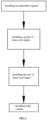
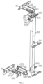
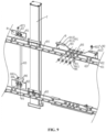
FIG. 1 is a schematic diagram of the whole process in the present disclosure; -
FIG. 2 is a state schematic diagram of a limiting tool, a level gauge and a tripod installed on a trolley; -
FIG. 3 is a structural schematic diagram of limiting parts; -
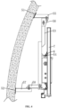
FIG. 4 is a structural schematic diagram after light columns are installed on a tunnel; -
FIG. 5 is a schematic diagram of the installation relation of light columns, beam steel angles and adjustable supports; -
FIG. 6 is a structural schematic diagram of an adjustable support; -
FIG. 7 is an exploded schematic diagram of an adjustable support; -
FIG. 8 is a structural schematic diagram of limiting measuring tools and horizontal measuring tools; -
FIG. 9 is a partial exploded schematic diagram in another angle of view; -
FIG. 10 is a partial sectioning schematic diagram of the connected relation of a limiting column and a first limiting plate on a limiting measuring tool; and -
FIG. 11 is a structural schematic diagram of an operating panel and second clamping grooves on a limiting measuring tool. - Reference signs in the attached
figures: 1 , trolley; 11, installation rack; 111, beam; 112, support beam; 113, connecting beam; 114, installation groove; 12, idler wheel; 121, baffle plate; 13, limiting part; 131, sliding block; 132, screw; 133, locking nut; 2, tripod; 21, installation clamp; 22, leg; 3, level gauge; 4, limiting tool; 41, placing rack; 42, limiting rod; 43, placing plate; 431, inserted hole; 5, adjustable support; 51, upper foundation plate; 52, lower foundation plate; 53, connecting rod; 531, third installation hole; 532, fourth waist-shaped hole; 54, connecting plate; 55, first upper connecting plate; 551, first waist-shaped hole; 56, second upper connecting plate; 561, first installation hole; 562, third waist-shaped hole; 57, first lower connecting plate; 571, second waist-shaped hole; 58, second lower connecting plate; 581, second installation hole; 582, fourth installation hole; 591, first adjusting bolt; 592, first adjusting nut; 593, second adjusting bolt; 594, second adjusting nut; 595, third adjusting bolt; 596, third adjusting nut; 597, fourth adjusting bolt; 598, fourth adjusting nut; 6, beam steel angle; 61, connecting part; 62, fixed part; 63, installation hole; 64, upper beam steel angle; 65, lower beam steel angle; 7, light column; 8, limiting measuring tool; 81, first limiting plate; 82, second limiting plate; 83, connecting plate; 84, limiting column; 841, clamping column; 842, screw; 843, screw cap; 844, clamping ring; 845, operating panel; 846, gasket; 847, abutting screw; 85, first auxiliary plate; 86, second auxiliary plate; 87, first clamping plate; 871, first positioning pin; 88, second clamping plate; 881, second positioning pin; 891, first clamping groove; 892, second clamping groove; 9, horizontal measuring tool; 91, clamping plate; 911, main plate; 912, side plate; 92, fixed part; 921, clamping column; 922, limiting pin; 93, avoiding groove; 94, assembly plate; 941, assembly hole; 95, connecting bolt; and 96, connecting nut. - The following describes the present disclosure in detail with reference to
FIG. 1 to FIG. 11 . - The embodiment of the present disclosure discloses an installing and positioning method for light columns of a tunnel media system. Referring to
FIG. 1 , the installing and positioning method for light columns of a tunnel media system comprises the following steps:
S1, installing anadjustable support 5;
When a train runs on a curve road section, due to the fact that the curve outer track is ultrahigh, one side of the train is high, the other side of the train is low, meanwhile, the center line of the train inclines, train windows of the train andlight columns 7 of the tunnel media system installed on the outer wall of a tunnel also inclined, and the angles and the distances of thelight columns 7 relative to the train windows are changed, and the display effect of thelight columns 7 seen by passengers in the train is seriously influenced. In order to reduce the change of the angles and the distances of thelight columns 7 relative to the train windows when the train runs on the curve road section, the display effect of the program is very good after the tunnel media system is installed in the section with the curve. During installation, theadjustable support 5 needs to be adjusted so that no matter how the train changes in inclination, the angles and distances between the sides, close to the train, of theadjustable supports 5 and the train are the same, and the angles and distances between thelight columns 7 installed on theadjustable supports 5 and the train are the same. Therefore, the step of adjusting the angle of the adjustable supporting 5 when theadjustable support 5 is installed specifically comprises the following steps:
S11, placing a trolley 1 on a track, installing a tripod 2 on the trolley 1, installing alevel gauge 3 on the tripod 2, and installing a limiting tool 4 on the trolley 1, wherein the limiting tool 4 is perpendicular to the trolley 1. - Referring to
FIG. 2 , the tripod 2 comprises aninstallation clamp 21 and threelegs 22 hinged to the lower side of theinstallation clamp 21, and thelevel gauge 3 can be installed on theinstallation clamp 21 directly. Wherein, the specific fixed mode of thelevel gauge 3 and the tripod 2 in the prior art is not described in detail here. - The trolley 1 comprises an installation rack 11 and four
idler wheels 12 rotatably connected to the lower side of the installation rack 11, wherein twoidler wheels 12 in a group are located at two ends of the installation rack 11 respectively, and the tripod 2 is installed on the installation rack 11. When in use, the two groups ofidler wheels 12 are directly placed on two tracks of the train respectively, the twoidler wheels 12 in the same group are placed on the same track, and then theidler wheels 12 are pulled to run on the tracks, so that the train can be simulated to run on the tracks. Wherein, thebaffle plate 121 is fixedly connected to the side, close to the other group ofidler wheels 12, of eachidler wheel 12 in order to prevent theidler wheels 12 from slipping off from the tracks, and when theidler wheels 12 are placed on the tracks, thebaffle plate 121 also abuts against one side of the track, so that the positions of theidler wheels 12 on the tracks are fixed, and theidler wheels 12 are prevented from slipping off from the tracks during movement. - The installation rack 11 comprises two
beams 111 and a plurality of support beams 112 fixedly connected between the twobeams 111, the support beams 112 are arranged at intervals along the length directions of thebeams 111, a connectingbeam 113 is further fixedly connected between two adjacent support beams 112, and the multiple support beams 112 can be connected through the connecting beams 113.Installation grooves 114 with inverted T-shaped sections are formed in the upper sides of thebeams 111, the support beams 112 and the connectingbeams 113, specifically, thebeams 111, the support beams 112 and the connectingbeams 113 can be made of aluminum profiles, and remachining of thebeams 111, the support beams 112 and the connectingbeams 113 can be avoided. During installation, the threelegs 22 on the tripod 2 are directly inserted into theinstallation grooves 114, and meanwhile, limitingparts 13 for fixing the positions of thelegs 22 in theinstallation grooves 114 are arranged in theinstallation grooves 114. - Referring to
FIG. 2 andFIG. 3 , the limitingparts 13 comprises a plurality of slidingblocks 131 slidingly connected in theinstallation grooves 114, two slidingblocks 131 are in a group, and the two slidingblocks 131 are located on two sides of theleg 22 for clamping theleg 22. Each slidingblock 131 is fixedly connected with a screw 132, each screw 132 is in threaded connection with a locking nut 133, and when the locking nut 133 is unscrewed, the slidingblock 131 can slide in theinstallation groove 114, so that the slidingblock 131 is moved to any position; when the slidingblocks 131 are moved to the two sides of thelegs 22, the locking nuts 133 are directly screwed, and the locking nuts 133 abut against the upper surfaces of the support beams 112 or the connectingbeams 113, so that the positions of the slidingblocks 131 in theinstallation grooves 114 are fixed, and the positions of thelegs 22 in theinstallation grooves 114 are fixed through the two slidingblocks 131. - Referring to
FIG. 2 andFIG. 3 , the limiting tool 4 comprises a placing rack 41 and a limitingrod 42 installed on the placing rack 41 by means of a hoop, the limitingrod 42 is perpendicular to the installation rack 11, and the limitingrod 42 also tilts when the installation rack 11 tilts due to the overheight of the outer track when the trolley 1 runs on the tracks, so that the tilting condition of the train running at the overheight position of the outer track is simulated. Wherein, the placing rack 41 is fixed on the installation rack 11 through the limitingparts 13. Specifically, a placingplate 43 is fixedly connected to the lower end of the placing rack 41, insertedholes 431 for the screws 132 to penetrate through are formed in the placingplate 43, the locking nuts 133 are located on the side, away from the installation frame 11, of the placingplate 43, the insertedholes 431 in the placing rack 41 are arranged on the screws 132 in a sleeving mode, then the locking nuts 133 are screwed, and then the position of the placingplate 43 can be fixed through the locking nuts 133, so that the position of the limiting tool 4 on the trolley 1 is fixed. - S12, installing an
adjustable support 5 on the side wall of a tunnel, and adjusting thelevel gauge 3, so that laser rays emitted by thelevel gauge 3 are located at the fixed position of theadjustable support 5. Wherein, the installation position of theadjustable support 5 is the position of a previously determined installation base line, the base line is determined by adjusting thelevel gauge 3 to be in an oblique line mode and then pushing the trolley 1, and the trolley 1 drives thelevel gauge 3 to draw a line with the radian consistent with that of the track on the side wall of the tunnel, so that the determined installation base line is parallel to the upper surfaces of the tracks. - Referring to
FIG. 4 andFIG.5 , a plurality ofadjustable supports 5 are arranged at intervals along the length direction of the tunnel, the adjustable support comprises anupper foundation plate 51 used for being fixedly connected with the side wall of the tunnel, alower foundation plate 52 used for being fixedly connected with the side wall of the tunnel and a connectingrod 53 arranged between theupper foundation plate 51 and thelower foundation plate 52, two connectingplates 54 are fixedly connected to the connectingrod 53, the two connectingplates 54 are perpendicularly and fixedly connected to the side, away from theupper foundation plate 51 and thelower foundation plate 52, of the connectingrod 53, the two connectingplates 54 are arranged at intervals along the length direction of the connectingrod 53, the two connectingplates 54 are used for being connected with thelight columns 7, and the distances between the two connectingplates 54 and the limiting tool 4 are adjusted, namely, the distance between the installedlight columns 7 relative to the train windows can be determined. - Referring to
FIG. 6 andFIG. 7 , a firstupper connecting plate 55 is fixedly connected to the side, away from the side wall of the tunnel, of theupper foundation plate 51, a secondupper connecting plate 56 is horizontally and slidably connected to one side of the firstupper connecting plate 55, the upper end of the connectingrod 53 is connected with the secondupper connecting plate 56, and the distance from the upper end of the connectingrod 53 to the limiting tooling 4 (referring toFIG. 2 ) can be adjusted by sliding the position of the secondupper connecting plate 56 on the firstupper connecting plate 55. Specifically, a first waist-shapedhole 551 is formed in the firstupper connecting plate 55, the length direction of the first waist-shapedhole 551 is consistent with the length of a straight line between the side wall of the tunnel and the limiting tool 4, afirst installation hole 561 is formed in the secondupper connecting plate 56, afirst adjusting bolt 591 is installed in the first waist-shapedhole 551 and thefirst installation hole 561, thefirst adjusting bolt 591 is in threaded connection with afirst adjusting nut 592, and the positions of the firstupper connecting plate 55 and the secondupper connecting plate 56 can be fixed through thefirst adjusting bolt 591 and thefirst adjusting nut 592. When thefirst adjusting bolt 591 is operated to slide in the first waist-shapedhole 551, thefirst adjusting bolt 591 can drive the secondupper connecting plate 56 to slide in the first waist-shapedhole 551 through the side wall of thefirst installation hole 561, and therefore horizontal sliding fit between the secondupper connecting plate 56 and the firstupper connecting plate 55 is achieved. - A first lower connecting
plate 57 is fixedly connected to the side, away from the side wall of the tunnel, of thelower foundation plate 52, a second lower connectingplate 58 is horizontally and slidably connected to one side of the first lower connectingplate 57, the lower end of the connectingrod 53 is connected with the second lower connectingplate 58, and by sliding the position of the second lower connectingplate 58 on the first lower connectingplate 57, the lower end of the connectingrod 53 can be driven to move along the length direction of the first lower connectingplate 57, and therefore the distance between the lower end of the connectingrod 53 and the limiting tool 4 is adjusted. Specifically, a second waist-shapedhole 571 is formed in the first lower connectingplate 57, asecond installation hole 581 is formed in the second lower connectingplate 58, asecond adjusting bolt 593 is installed in the second waist-shapedhole 571 and thesecond installation hole 581, and thesecond adjusting bolt 593 is in threaded connection with asecond adjusting nut 594. The position of the second lower connectingplate 58 on the first lower connectingplate 57 can be fixed through thesecond adjusting bolt 593 and thesecond adjusting nut 594, meanwhile, thesecond adjusting bolt 593 is operated to slide in the second waist-shapedhole 571, thesecond adjusting bolt 593 drives the second lower connectingplate 58 to slide along the length direction of the second wait-shapedhole 571 through the hole wall of thesecond installation hole 581, and therefore, horizontal sliding fit between the second lower connectingplate 58 and the first lower connectingplate 57 is achieved. By simultaneously operating the secondupper connecting plate 56 to slide along the length direction of the firstupper connecting plate 55 and the second lower connectingplate 58 to slide along the length direction of the first lower connectingplate 57, the distance between the connectingrod 53 and the limiting tool 4 can be adjusted, so that the distances between the two connectingplates 54 perpendicularly and fixedly connected to the connectingrod 53 and the limiting tool 4 are the same. - The upper end and the lower end of the connecting
rod 53 are in vertical sliding fit with the secondupper connecting plate 56 and the second lower connectingplate 58 respectively, the height of the connectingplate 54 fixedly connected to the connectingrod 53 can be adjusted by operating the upper end and the lower end of the connectingrod 53 to perpendicularly slide on the secondupper connecting plate 56 and the second lower connectingplate 58, and therefore the heights of thelight columns 7 installed on the connectingplate 54 are adjusted. Specifically, a vertical third waist-shapedhole 562 is formed in the secondupper connecting plate 56, athird installation hole 531 is formed in the upper end of the connectingrod 53, athird adjusting bolt 595 is installed in the third waist-shapedhole 562 and thethird installation hole 531, thethird adjusting bolt 595 is in threaded connection with athird adjusting nut 596, the position between the connectingrod 53 and the secondupper connecting plate 56 can be fixed through thethird adjusting bolt 595 and thethird adjusting nut 596, and the height of the upper end of the connectingrod 53 can be adjusted by operating thethird adjusting bolt 595 to slide in the third waist-shapedhole 562. Afourth installation hole 582 is formed in the second lower connectingplate 58, a vertical fourth waist-shapedhole 532 is formed in the lower end of the connectingrod 53, afourth adjusting bolt 597 is installed in the fourth waist-shapedhole 532 and thefourth installation hole 582, thefourth adjusting bolt 597 is in bolted connection with afourth adjusting nut 598, the position between the lower end of the connectingrod 53 and the second lower connectingplate 58 can be fixed through thefourth adjusting bolt 597 and thefourth adjusting nut 598, and the height of the lower end of the connectingrod 53 can be adjusted by operating thefourth adjusting bolt 597 to slide in the fourth waist-shapedhole 532. Meanwhile, when the secondupper connecting plate 56 is adjusted to slide on the firstupper connecting plate 55 or the second lower connectingplate 58 is adjusted to slide on the first lower connectingplate 57, the upper end of the connectingrod 53 also rotates around thethird adjusting bolt 595, and the lower end of the connectingrod 53 also rotates around thefourth adjusting bolt 597, so that the inclination degree of the connectingrod 53 is adjusted, and the connectingrod 53 is parallel to the limiting tool 4, namely, the light columns installed on the two connectingplates 54 are parallel to the train windows. - During installation, the positions of the
first adjusting bolt 591 in the middle of the first waist-shapedhole 551 and thesecond adjusting bolt 593 in the middle of the second waist-shapedhole 571 are adjusted in advance, then the positions of thethird adjusting bolt 595 in the middle of the third waist-shapedhole 562 and thefourth adjusting bolt 597 in the middle of the fourth waist-shapedhole 532 are adjusted, then theupper foundation plate 51 and thelower foundation plate 52 are installed and fixed, and thefirst adjusting bolt 591, thesecond adjusting bolt 593, thethird adjusting bolt 595 and thefourth adjusting bolt 597 are all adjusted to the middle positions, so that the installedadjustable supports 5 can be correspondingly and accurately adjusted subsequently. - When the
level gauge 3 is adjusted, thelevel gauge 3 is adjusted in an oblique line mode. When thelevel gauge 3 is in a straight line mode, on the premise that the relative height of thelevel gauge 3 is not changed, the horizontal lines emitted by thelevel gauge 3 within 3 degrees of the inclination angle are completely overlapped. When the inclination angle exceeds 3 degrees, relative positions of the laser rays emitted by thelevel gauge 3 are linearly lifted or lowered. Therefore, when thelevel gauge 3 is used in a straight line mode, certain errors are generated. When thelevel gauge 3 is adjusted in an oblique line mode and the track changes slightly in radian, the laser rays emitted by thelevel gauge 3 changes correspondingly, so that the radians of the laser rays emitted by thelevel gauge 3 are consistent with those of the tracks. Therefore, when the tracks change little, the laser rays emitted by thelevel gauge 3 do not change, and errors between the emitted laser rays and the radians of the tracks can be avoided. - The present disclosure discloses a method for adjusting the oblique line mode of a Leocel LS639
type level gauge 3 by taking the Leocel LS639type level gauge 3 as an example, firstly, when a bubble in thelevel gauge 3 is adjusted to be in the middle position, a switch of thelevel gauge 3 is turned on, three keys of V1, V2and H on thelevel gauge 3 are pressed, the height of the tripod 2 is adjusted to a required installation height, and in the disclosure, the laser lines are adjusted to hit at the center position of the connectingplate 54 at the upper part of the connectingrod 53. Then, the switch of thelevel gauge 3 is turned off, the key of oblique line mode on thelevel gauge 3 is pressed down, and the three keys of V1, V2 and H of thelevel gauge 3 are pressed down again. At this point, another red "+" appears on the connectingplate 54 at the upper part of the connectingrod 53; next, any two legs of the tripod 2 are adjusted so that the center of the cross laser rays emitted by infrared rays of thelevel gauge 3 is located at the center of the connectingplate 54 at the upper part of the connectingrod 53, which is the installation height in the oblique line mode. Thelevel gauge 3 is driven by the trolley 1 to run on the tracks, and thelevel gauge 3 can draw a line parallel to the upper surfaces of the tracks, so that theadjustable support 5 can be conveniently positioned during installation. - S13, adjusting the
adjustable support 5, so that the linear distance from the upper end of theadjustable support 5 to the limiting tool 4 is the same as that from the lower end of theadjustable support 5 to the limiting tool 4. - Specifically, after the
upper foundation plate 51 and thelower foundation plate 52 are fixed to the side wall of the tunnel through anchor bolts, the centers of the laser rays emitted by thelevel gauge 3 are located at the center of the connectingplate 54 located at the upper end of the connectingrod 53 by adjusting the height of the connectingrod 53, and meanwhile a first mark and a second mark are made on the limiting tool 4 through a marking pen or adhesive tape and the like, and then the linear distance between the two connectingplates 54 to the limitingrod 42, namely, the distance between the connectingplate 54 located at the upper end of the connectingrod 53 and the first marking, and the distance between the connectingplate 54 located at the lower end of the connectingrod 53 and the second mark, are measured by a box ruler. Thefirst adjusting bolt 591 is adjusted to slide in the first waist-shapedhole 551, and thesecond adjusting bolt 593 is adjusted to slide in the second waist-shapedhole 571, so that the distances between the two connectingplates 54 and the limitingrod 42 are consistent, and at the moment, thefirst adjusting bolt 591, thesecond adjusting bolt 593, thethird adjusting bolt 595 and thefourth adjusting bolt 597 are locked, so that the installation of theadjustable bracket 5 can be completed. - S14, pushing the trolley 1 to advance on the track, installing a next
adjustable support 5, so that the laser rays emitted by thelevel gauge 3 are located at the fixed positions of theadjustable support 5, the linear distance from the upper end of theadjustable support 5 to the limiting tool 4 is the same as that from the lower end of theadjustable support 5 to the limiting tool 4, and circulation is conducted in sequence until all theadjustable supports 5 are installed completely. - When each
adjustable support 5 is installed, theadjustable supports 5 need to be installed on an installation base line determined in the earlier stage, the connectingrod 53 is adjusted so that the laser rays emitted by thelevel gauge 3 are located in the middle of the connectingplate 54 located at the upper end of the connectingrod 53, then the distance between one connectingplate 54 located at the upper end of the connectingrod 53 and the first mark and the distance between the other connectingplate 54 at the lower end of the connectingrod 53 and the second mark are measured through the box ruler, by adjusting the position of thefirst adjusting bolt 591 in the first waist-shapedhole 551 and the position of thesecond adjusting bolt 593 in the second waist-shapedhole 571, the distances between the two connectingplates 54 on eachadjustable support 5 and the limitingrod 42 are equal, and therefore, each installedlight column 7 is parallel to the train window of the train, and the distances between thelight columns 7 and the train windows are equal. - S2, installing
beam steel angles 6, wherein referring toFIG. 8 andFIG. 9 , twobeam steel angles 6 are in a group, and multiple groups ofbeam steel angles 6 are arranged side by side along the length direction of the tunnel media system. The section of thebeam steel angle 6 is in an L shape, thebeam steel angle 6 comprises a connectingpart 61 fixedly connected with the connectingplate 54 and afixed part 62 perpendicularly and fixedly connected to the side, away from the connectingrod 53, of the connectingpart 61, the connectingpart 61 is placed on the connectingplate 54 and attached to the upper surface of the connectingplate 54, and the connectingpart 61 and the connectingplate 54 are fixedly connected through fixed bolts, and thefixed part 62 is used for being connected with thelight column 7 so as to fix the position of thelight column 7. Meanwhile, installation holes 63 connected with thelight columns 7 are formed in the fixedpart 62 of eachbeam steel angle 6 at intervals along the length direction of the fixedpart 62. - The two
beam steel angles 6 in the same group comprise an upperbeam steel angle 64 installed the connectingplate 54 at the upper part of the connectingrod 53 and a lowerbeam steel angle 65 installed on the connectingplate 54 at the lower part of the connectingrod 53. During installation, the twobeam steel angles 6 in the same group are installed firstly, the upperbeam steel angle 64 is installed on the connectingplate 54 at the upper part of theadjustable support 5, then the lowerbeam steel angle 65 is placed on the connectingplate 54 at the lower part of theadjustable support 5, then the upper end and the lower end of the limiting measuring tool 8 are clamped in the installation holes 63 in the corresponding positions of the upperbeam steel angle 64 and the lowerbeam steel angle 65 respectively, the limiting measuring tool 8 is perpendicular to the twobeam steel angles 6 at the same time, and finally the position of the lowerbeam steel angle 65 on theadjustable support 5 is fixed; the position between the upperbeam steel angle 64 and the lowerbeam steel angle 65 in the same group can be fixed through the limiting measuring tool 8, so that the installation holes 63 in the corresponding positions of the upperbeam steel angle 64 and the lowerbeam steel angle 65 in the same group are in the same vertical plane. Namely, the upper end and the lower end of thelight column 7 installed in theinstallation hole 63 are located in the same vertical plane, so that theinstallation light columns 7 cannot incline, and the probability that the installedlight columns 7 incline is greatly reduced. - Referring to
FIG. 8 andFIG. 9 , the limiting measuring tool 8 comprises a first limitingplate 81 attached to the side, away from the connectingrod 53, of the upperbeam steel angle 64, a second limitingplate 82 attached to the side, away from the connectingrod 53, of the lowerbeam steel angle 65, and a connectingplate 83 arranged between the first limitingplate 81 and the second limitingplate 82. The side, facing the upperbeam steel angle 64, of the first limitingplate 81 and the side, facing the lowerbeam steel angle 65, of the second limitingplate 82 are fixedly connected with limitingcolumns 84, wherein the sections of the limitingcolumns 84 are non-circular, and the limitingcolumns 84 on the first limitingplate 81 and the second limitingplate 82 are respectively matched with the installation holes 63 in the upperbeam steel angle 64 and the lowerbeam steel angle 65 in an inserted mode. Specifically, the section of the limitingcolumn 84 can be rectangular, oval, rhombic or in other irregular shapes, so long as the limitingcolumn 84 is inserted into theinstallation hole 63, the limitingcolumn 84 can be matched with theinstallation hole 63 in an inserted mode, and the limitingcolumn 84 can be prevented from rotating in theinstallation hole 63, so that the upperbeam steel angle 64 and the lowerbeam steel angle 65 are both perpendicular to the limiting measuring tool 8. In the present disclosure, the section of the limitingcolumn 84 is rectangular. When in use, the connectingplate 83 is directly operated to insert the two limitingcolumns 84 into the installation holes 63 in the upperbeam steel angle 64 and the lowerbeam steel angle 65, and the connectingplate 83 is perpendicular to the upperbeam steel angle 64 and the lowerbeam steel angle 65 at the same time, so that the installation holes 63 in the corresponding positions of the upperbeam steel angle 64 and the lowerbeam steel angle 65 are located in the same vertical plane. - Referring to
FIG. 9 andFIG. 10 , the limitingcolumn 84 comprises a rectangular clamping column 841, ascrew 842 fixedly connected to one end of the clamping column 841, a clamping ring 844 fixedly connected to the outer wall of the clamping column 841 and anut 843 in threaded connection to thescrew 842, wherein the clamping ring 844 is located at the end, close to thescrew 842, of the clamping column 841, the circumference of the clamping ring 844 is larger than that of thescrew 842, and first clampinggrooves 891 for embedding thescrews 842 are formed in the first limitingplate 81 and the second limitingplate 82. When in use, the end, away from the clamping column 841, of thescrew 842 is directly inserted into thefirst clamping groove 891, at the moment, the clamping ring 844 abuts against the first limitingplate 81 or the second limitingplate 82, then thenut 843 is screwed on thescrew 842, and thenut 843 and the clamping ring 844 are clamped on the two sides of the first limitingplate 81 or the second limitingplate 82. Therefore, the position of the limitingcolumn 84 on the first limitingplate 81 or the second limitingplate 82 is fixed, when the limitingcolumn 84 needs to be disassembled, thenut 843 is directly screwed down from thescrew 842, and detachable connection of the limitingcolumn 84 is achieved. Due to the detachable connection of the limitingcolumn 84, the limitingcolumn 84 can be detached and replaced as required to meet the requirements of the installation holes 63 with different shapes and sizes, and the disclosure range is wider. - Wherein, the side, facing the connecting
plate 83, of the first limitingplate 81 is perpendicularly and fixedly connected with a firstauxiliary plate 85, and the firstauxiliary plate 85 is located on the side, away from the limitingcolumn 84, of the first limitingplate 81; and the side, facing the connectingplate 83, of the second limitingplate 82 is perpendicularly and fixedly connected with a secondauxiliary plate 86, and the secondauxiliary plate 86 is located on the side, away from the limitingcolumn 84, of the first limitingplate 81. The connectingplate 83 is perpendicularly and fixedly connected between the firstauxiliary plate 85 and the secondauxiliary plate 86, the connectingplate 83 can be operated to drive the limitingcolumns 84 located on the first limitingplate 81 and the second limitingplate 82 to be inserted into the installation holes 63 through the firstauxiliary plate 85 and the secondauxiliary plate 86, and limitation of the upperbeam steel angle 64 and the lowerbeam steel angle 65 is achieved. - Wherein, in order to prevent the limiting
columns 84 from sliding out of the installation holes 63 in the upperbeam steel angle 64 and the lowerbeam steel angle 65 under the action of external force, the relative position between the upperbeam steel angle 64 and the lowerbeam steel angle 65 is changed. The side, away from the connectingplate 83, of the first limitingplate 81 is perpendicularly and fixedly connected with afirst clamping plate 87, thefirst clamping plate 87 is located on the side, facing the limitingcolumn 84, of the first limitingplate 81, afirst positioning pin 871 is inserted into thefirst clamping plate 87 in a matched mode, thefirst positioning pin 871 is located on the side, away from the first limitingplate 81, of the upperbeam steel angle 64, the upperbeam steel angle 64 can be clamped between thefirst positioning pin 871 and the first limitingplate 81 through thefirst positioning pin 871, so that the position between the upperbeam steel angle 64 and the first limitingplate 81 is fixed. The side, away from the connectingplate 83, of the second limitingplate 82 is perpendicularly and fixedly connected with asecond clamping plate 88, thesecond clamping plate 88 is located on the side, facing the limitingcolumn 84, of the second limitingplate 82, asecond positioning pin 881 is inserted into thesecond clamping plate 88 in a matched mode, thesecond positioning pin 881 is located on the side, away from the second limitingplate 88, of the lowerbeam steel angle 65, the lowerbeam steel angle 65 can be clamped between thesecond positioning pin 881 and the second limitingplate 82 through thesecond positioning pin 881, so that the position between the lowerbeam steel angle 65 and the second limitingplate 82 is fixed. During installation, after the limitingcolumns 84 on the first limitingplate 81 and the second limitingplate 82 are inserted into the installation holes 63 in the upperbeam steel angle 64 and the lowerbeam steel angle 65, thefirst positioning pin 871 is directly inserted into thefirst clamping plate 87, thesecond positioning pin 881 is directly inserted into thesecond clamping plate 88, the positions of the limiting measuring tool 8 and the upperbeam steel angle 64 and the positions of the limiting measuring tool 8 and the lowerbeam steel angle 65 can be fixed, so that the installation holes 63 in the corresponding positions of the upperbeam steel angle 64 and the lowerbeam steel angle 65 are located in the same vertical plane, the two ends of thelight columns 7 installed on the upperbeam steel angle 64 and the lowerbeam steel angle 65 are ensured to be in a vertical state, and the probability that the installedlight columns 7 incline is greatly reduced. - Wherein, the number of the limiting
columns 84 located on the first limitingplate 81 is two, the direction of a connecting line between the two limitingcolumns 84 is perpendicular to the length direction of the connectingplate 83, and the two limitingcolumns 84 are matched with the twoinstallation holes 63 in the upperbeam steel angle 64 in an inserted mode respectively, so that limitation of the upperbeam steel angle 64 is more accurate, and relative movement of the upperbeam steel angle 64 is avoided. The number of the limitingcolumns 84 located on the second limitingplate 82 is two, the direction of a connecting line between the two limitingcolumns 84 is perpendicular to the length direction of the connectingplate 83, and the two limitingcolumns 84 are matched with the twoinstallation holes 63 in the lowerbeam steel angle 65 in an inserted mode respectively, so that limitation of the lowerbeam steel angle 65 is more accurate through the two limitingcolumns 84, and relative movement of the lowerbeam steel angle 65 is avoided. - In actual use, the distance between the installed upper
beam steel angle 64 and the installed lowerbeam steel angle 65 may generate certain errors, so that the limitingcolumn 84 located on the first limitingplate 81 and the limitingcolumn 84 located on the second limitingplate 82 cannot be inserted into the installation holes 63 in the upperbeam steel angle 64 and the lowerbeam steel angle 65 at the same time. - Referring to
FIG. 9 andFIG. 11 , twosecond clamping grooves 892 communicating with thefirst clamping grooves 891 are formed in the second limitingplate 82, and the twosecond clamping grooves 892 communicate with the twofirst clamping grooves 891 respectively, so that eachfirst clamping groove 891 and thesecond clamping groove 892 communicating with thefirst clamping groove 891 jointly form a waist-shaped hole consistent with the connectingplate 83 in length, and the two limitingcolumns 84 located on the second limitingplate 82 can slide in the two waist-shaped holes, so that a certain activity space is provided. When the distance between the upperbeam steel angle 64 and the lowerbeam steel angle 65 generates certain errors, the limitingcolumn 84 on the second limitingplate 82 can be operated to slide in the waist-shaped hole until the limitingcolumn 84 is inserted into theinstallation hole 63 in the lowerbeam steel angle 65, and positioning of the upperbeam steel angle 64 and the lowerbeam steel angle 65 is achieved. - Wherein, in order to conveniently operate the limiting
column 84 located on the second limitingplate 82 to slide in the waist-shaped hole, anoperating panel 845 is arranged between the two limitingcolumns 84 located on the second limitingplate 82, theoperating panel 845 is arranged on thescrews 842 of the two limitingcolumns 84 in a sleeving mode, and theoperating panel 845 is located between thenut 843 and the second limitingplate 82. A worker can drive the two limitingcolumns 84 to slide in the two waist-shaped holes respectively at the same time by directly applying force to theoperating plate 845, and the operation is more convenient. Wherein, in order to conveniently slide theoperating panel 845, the twoscrews 842 located on the second limitingplate 82 are sleeved withgaskets 846, and thegaskets 846 are located between the second limitingplate 82 and theoperating panel 845, so that a certain gap is reserved between the operatingpanel 845 and the second limitingplate 82, and the operation is more convenient and labor-saving. - Meanwhile, in order to fix the position of the
operating panel 845 on the second limitingplate 82 and prevent theoperating panel 845 from driving the two limitingcolumns 84 to slide in the waist-shaped holes under the action of external force, theoperating panel 845 is in threaded connection with anabutting screw 847, and theabutting screw 847 can abut against the side, away from the clamping ring 844, of the second limitingplate 82, so that the second limitingplate 82 is clamped between theabutting screw 847 and the clamping ring 844, and the position of theoperating panel 845 relative to the second limitingplate 82 is fixed. - S3, sequentially installing the rest of the beam steel angles 6 on the
adjustable support 5;
specifically, S31, determining the distance between two adjacent upper beam steel angles 64 and the distance between two adjacent lower beam steel angles 65 through horizontal measuring tools 9. - After the first group of beam steel angles 6 is installed, the rest of
beam steel angles 6 need to be installed in sequence, and as the installation length of the tunnel media system is fixed, when two adjacent upper beam steel angles 64 and two adjacent lower beam steel angles 65 are connected through bolts, due to the fact that the difference between the diameter of the bolt and the diameter of the threaded hole is generally 2 mm, a certain error exists between the upperbeam steel angle 64 or the lowerbeam steel angle 65 after installation, when the error is accumulated to a certain value, the overall length of the tunnel media system can be affected, and meanwhile, when the errors of the upperbeam steel angle 64 and the lowerbeam steel angle 65 are inconsistent, thelight columns 7 installed in the corresponding installation holes 63 can incline. In order to ensure that the distance between two adjacent upper beam steel angles 64 and two adjacent lower beam steel angles 65 is fixed and reduce errors generated during installation, the two adjacent upper beam steel angles 64 or two adjacent lower beam steel angles 65 need to be installed by means of the horizontal measuring tools 9, and the distance between two adjacent upper beam steel angles 64 and two adjacent lower beam steel angles 65 can be fixed through the horizontal measuring tools 9. - Referring to
FIG. 8 andFIG. 9 , the horizontal measuring tool 9 comprises a clamping plate 91 and afixed part 92, wherein the clamping plate 91 is integrally U-shaped, opposite ends of two adjacent upper beam steel angles 64 or two adjacent lower beam steel angles 65 can be embedded into the clamping plate 91, the fixedpart 92 is used for fixing the positions of the upper beam steel angles 64 or the lower beam steel angles 65 in the clamping plate 91, and thefixed part 92 is located in a U-shaped opening of the clamping plate 91. During installation, the opposite ends of the two adjacent upper beam steel angles 64 or the two adjacent lower beam steel angles 65 are directly placed in the U-shaped openings of the clamping plates 91, and then the positions of the two upper beam steel angles 64 or the two lower beam steel angles 65 in the clamping plate 91 are fixed through the fixedpart 92. - Wherein, the clamping plate 91 comprises a main plate 911 and two side plates 912 perpendicularly and fixedly connected to the two sides of the main plate 911, the fixed
part 92 comprises two clampingcolumns 921 fixedly connected to the sides, facing the two side plates 912, of the main plate 911, the section of theclamping column 921 is consistent with theinstallation hole 63 in shape and are rectangula, and the clampingcolumns 921 are matched with the installation holes 63 in an inserted mode and cannot shake in the installation holes 63. During installation, two adjacent upper beam steel angles 64 or two adjacent lower beam steel angles 65 are directly placed in the U-shaped openings of the clamping plates 91, and the two clampingcolumns 921 are inserted into the installation holes 63 in the two adjacent upper beam steel angles 64 or the two adjacent lower beam steel angles 65 respectively. Due to the fact that theclamping column 921 cannot slide in theinstallation hole 63, the relative position between two adjacent upper beam steel angles 64 or two adjacent lower beam steel angles 65 can be fixed. - Meanwhile, the situation that under the action of external force, the two adjacent upper beam steel angles 64 or the two adjacent lower beam steel angles 65 slide out of the U-shaped openings of the clamping plates 91, so that the
clamping column 921 falls out of theinstallation hole 63, and positioning between the two adjacent upper beam steel angles 64 or the two adjacent lower beam steel angles 65 is affected is avoided. A limitingpin 922 is inserted into one side plate 912 in a matched mode and located on the side, away from the main plate 911, of the upperbeam steel angle 64 or the lowerbeam steel angle 65, and the upperbeam steel angle 64 or the lowerbeam steel angle 65 can be fixed between the limitingpin 922 and the main plate 911 through the limitingpin 922, so that the positions of the upperbeam steel angle 64 and the lowerbeam steel angle 65 are fixed. - S32, after the position between two adjacent upper beam steel angles 64 or two adjacent lower beam steel angles 65 is fixed through the horizontal measuring tools 9, detecting the positions of the installation holes 63 at the corresponding positions of the upper
beam steel angle 64 and the lowerbeam steel angle 65 in the same group by using the limiting measuring tools 8; and detecting the relative positions of the upperbeam steel angle 64 and the lowerbeam steel angle 65 of each group through the limiting measuring tool 8, so that the twoinstallation holes 63 of the same group in the corresponding positions are located in the same vertical plane, and then fixing the positions of the upperbeam steel angle 64 and the lowerbeam steel angle 65 of the group on theadjustable support 5. - S33, connecting two adjacent upper beam steel angles 64 or two adjacent lower beam steel angles 65 through assembly plates 94, and then taking down the horizontal measuring tools 9 between the two adjacent upper beam steel angles 64 or the two adjacent lower beam steel angles 65.
- Referring to
FIG. 9 , the assembly plate 94 is plate-shaped, at least twoassembly holes 941 are formed in the assembly plate 94, and the twoassembly holes 941 correspond to the installation holes 63 in the opposite ends of the two adjacent upper beam steel angles 64 or the two adjacent lower beam steel angles 65 respectively. In the present disclosure, fourassembly holes 941 are taken as an example, twoinstallation holes 63 formed in the end part of each upper crossbeam steel angle 64 or lower crossbeam steel angle 65 correspond to the assembly holes 941. A connectingbolt 95 is arranged in theassembly hole 941 in a penetrating mode, and a connectingnut 96 is connected to the connectingbolt 95 in a threaded mode. The connectingbolts 95 penetrate through the installation holes 63 and the assembly holes 941 in the end parts of the upper beam steel angles 64 or the lower beam steel angles 65 at the same time, so that the assembly plate 94 can be connected with the two adjacent upper beam steel angles 64 or the assembly plate 94 can be connected with the two adjacent lower beam steel angles 65 through the connectingbolts 95 and the connecting nuts 96. - Meanwhile, in order to prevent the distance between two adjacent upper beam steel angles 64 or two adjacent lower beam steel angles 65 from changing in the installation process of the assembly plate 94, during installation, the two adjacent upper beam steel angles 64 or the two adjacent lower beam steel angles 65 are connected through the assembly plate 94, and then the horizontal measuring tools 9 are taken down. Therefore, an avoiding
groove 93 for embedding the assembly plate 94 is formed in one side of the clamping plate 91, and the avoidinggroove 93 is formed in the middle of one side plate 912 where the limitingpin 922 is inserted and the main plate 911 at the same time. During installation, the assembly plate 94 is directly placed at the joint of the two upper beam steel angles 64 or the two lower beam steel angles 65 from the avoidinggroove 93, and the two upper beam steel angles 64 and the assembly plate 94 or the two lower beam steel angles 65 and the assembly plate 94 are connected together through the connectingbolts 95. Therefore, the relative position between two adjacent upper beam steel angles 64 or two adjacent lower beam steel angles 65 can be fixed, and then the horizontal measuring tools 9 are taken down. Circulation is conducted in sequence until all theadjustable supports 5 are installed completely. - S4, installing the
light columns 7 at the installation holes 63 at the corresponding positions of the upper and lowerbeam steel angles 6 through bolts. - The implementation principle of the installing and positioning method for light columns of a tunnel media system is that the relative position relation between the upper beam steel angles 64 and the lower beam steel angles 65 can be fixed through the limiting measuring tools 8, so that the installation holes 63 in the upper
beam steel angle 64 and the lowerbeam steel angle 65 in the same group are located in the same vertical plane, and the probability that the installedlight columns 7 incline is reduced. The relative position between two adjacent upper beam steel angles 64 or two adjacent lower beam steel angles 65 can be fixed through the horizontal measuring tools 9, errors caused by connection of the two steel angles are reduced, and it is guaranteed that the length of the installed upper beam steel angles 64 or the installed lowerbeam steel angle 65 is consistent with that of the tunnel media system, and then the installation holes 63 in the corresponding positions of the upperbeam steel angle 64 and the lowerbeam steel angle 65 of each group are in the same vertical plane, the upperbeam steel angle 64 and the lowerbeam steel angle 65 of each group are detected through the limiting measuring tool 8, the two ends of each installedlight column 7 are located in the same plane, and the probability that the installedlight columns 7 incline is greatly reduced. Meanwhile, when theadjustable support 5 is installed, the distances between theadjustable supports 5 and the limiting tool 4 are adjusted to be consistent, and the inclination degree of theadjustable support 5 is consistent with that of the limiting tool, so that the distances between thelight columns 7 installed on theadjustable support 5 and the train window are consistent, and the inclination degree of theadjustable support 5 is consistent with that of the train, so that the video animation played by the installed tunnel media system is attached to the train window, and the display effect is better.
Claims (8)
- An installing and positioning method for light columns of a tunnel media system, comprising following steps:S1, installing an adjustable support (5);S2, installing a first group of beam steel angles (6), comprising following steps:forming installation holes (63) in each beam steel angle (6) at intervals along a length direction of each beam steel angle (6),firstly installing a first beam steel angle (6), called an upper beam steel angle, on a connecting plate on an upper side of the adjustable support (5),then installing a second beam steel angle (6), called a lower beam steel angle, on a connecting plate (54) on a lower side of the adjustable support (5),and clamping upper ends and lower ends of a limiting measuring tool (8) in the installation holes (63) in corresponding positions of upper and lower beam steel angles (6) respectively in which the limiting measuring tool (8) is perpendicular to the two beam steel angles (6) at the same time,and finally fixing the position of the beam steel angle (6) located on the connecting plate (54) on the lower side on the adjustable support (5); characterized in that,the limiting measuring tool (8) comprises a first limiting plate (81) attached to a side, away from the adjustable support (5), of the upper beam steel angle (64),a second limiting plate (82) attached to a side, away from the adjustable support (5), of the lower beam steel angle (65),and a connecting plate (83) arranged between the first limiting plate (81) and the second limiting plate (82),a side, facing the upper beam steel angle (64), of the first limiting plate (81) and a side, facing the lower beam steel angle (65), of the second limiting plate (82) are fixedly connected with limiting columns (84),sections of the limiting columns (84) are non-circular,and the limiting columns (84) on the first limiting plate (81) and the second limiting plate (82) are respectively matched with the installation holes (63) in the upper beam steel angle (64) and the lower beam steel angle (65) in an inserted mode;and a side, away from the connecting plate (83) of the limiting measuring tool (8), of the first limiting plate (81) is fixedly connected with a first clamping plate (87),a first positioning pin (871) is inserted into the first clamping plate (87),the upper beam steel angle (64) is located between the first positioning pin (871) and the first limiting plate (81),a side, facing the connecting plate (83) of the limiting measuring tool (8), of the second limiting plate (82) is fixedly connected with a second clamping plate (88),a second positioning pin (881) is inserted into the second clamping plate (88),and the lower beam steel angle (65) is located between the second positioning pin (881) and the second limiting plate (82);S3, sequentially installing, side by side along the length direction of the tunnel media system, the rest of the groups of beam steel angles (6) on the adjustable support (5) in a likewise manner as shown in S2; andS4, installing the light columns (7) at the installation holes (63) at the corresponding positions of the upper and lower beam steel angles (6).
- The installing and positioning method for light columns of a tunnel media system according to claim 1, wherein S3 specifically comprises a following step:
S31, determining a distance between two adjacent upper beam steel angles (64) and a distance between two adjacent lower beam steel angles (65) through horizontal measuring tools (9). - The installing and positioning method for light columns of a tunnel media system according to claim 2, wherein the horizontal measuring tool (9) comprises a clamping plate (91) which is integrally U-shaped, the clamping plate (91) is connected to opposite ends of two adjacent upper beam steel angles (64) or two adjacent lower beam steel angles (65), and the clamping plate (91) is provided with a fixed part (92) for fixing the upper beam steel angle (64) or the lower beam steel angle (65) in the clamping plate (91).
- The installing and positioning method for light columns of a tunnel media system according to claim 3, wherein the clamping plate (91) comprises a main plate (911) and two side plates (912) perpendicularly and fixedly connected to two sides of the main plate (911), the fixed part (92) comprises a clamping column (921) arranged on a side, facing the side plate (912), of the main plate (911), and the clamping column (921) is matched with the installation hole (63) in an inserted mode.
- The installing and positioning method for light columns of a tunnel media system according to claim 4, wherein the fixed part (92) further comprises a limiting pin (922) connected to one of the side plates (912) in an inserted mode, and the upper beam steel angle (64) or the lower beam steel angle (65) is located between the limiting pin (922) and the main plate (911).
- The installing and positioning method for light columns of a tunnel media system according to claim 2, wherein S3 further comprises a following step:
S32, detecting relative positions of the upper beam steel angle (64) and the lower beam steel angle (65) of each group through the limiting measuring tool (8), so that two installation holes (63) of the same group are located in a same vertical plane, and then fixing positions of the upper beam steel angle (64) and the lower beam steel angle (65) of the group on the adjustable support (5). - The installing and positioning method for light columns of a tunnel media system according to claim 2, wherein S3 further comprises a following step:
S33, connecting two adjacent upper beam steel angles (64) or two adjacent lower beam steel angles (65) through assembly plates (94), and then taking down the horizontal measuring tools (9) between the two adjacent upper beam steel angles (64) or the two adjacent lower beam steel angles (65). - The installing and positioning method for light columns of a tunnel media system according to claim 7, wherein S1 specifically comprises following steps:S11, placing a trolley (1) on a track, installing a tripod (2) on the trolley (1), installing a level gauge (3) on the tripod (2), and installing a limiting tool (4) on the trolley (1), wherein the limiting tool (4) is perpendicular to the trolley (1);S12, installing an adjustable support (5) on a side wall of a tunnel, and adjusting the level gauge (3), so that laser rays emitted by the level gauge (3) are located at a fixed position of the adjustable support (5);S13, adjusting the adjustable support (5), so that a linear distance from an upper end of the adjustable support (5) to the limiting tool (4) is the same as that from a lower end of the adjustable support (5) to the limiting tool (4); andS14, pushing the trolley (1) to advance on the track, installing a next adjustable support (5), so that the laser rays emitted by the level gauge (3) are located at fixed positions of the adjustable support (5), a linear distance from an upper end of the adjustable support (5) to the limiting tool (4) is the same as that from a lower end of the adjustable support (5) to the limiting tool (4), and circulation is conducted in sequence until all the adjustable supports (5) are installed completely.
Applications Claiming Priority (1)
| Application Number | Priority Date | Filing Date | Title |
|---|---|---|---|
| CN202011640943.2A CN112856172B (en) | 2020-12-31 | 2020-12-31 | Mounting and positioning method for tunnel media system light column |
Publications (3)
| Publication Number | Publication Date |
|---|---|
| EP4024376A1 EP4024376A1 (en) | 2022-07-06 |
| EP4024376C0 EP4024376C0 (en) | 2023-08-09 |
| EP4024376B1 true EP4024376B1 (en) | 2023-08-09 |
Family
ID=76000764
Family Applications (1)
| Application Number | Title | Priority Date | Filing Date |
|---|---|---|---|
| EP21215996.6A Active EP4024376B1 (en) | 2020-12-31 | 2021-12-20 | Installing and positioning method for light columns of tunnel media system |
Country Status (2)
| Country | Link |
|---|---|
| EP (1) | EP4024376B1 (en) |
| CN (1) | CN112856172B (en) |
Families Citing this family (2)
| Publication number | Priority date | Publication date | Assignee | Title |
|---|---|---|---|---|
| CN116085606B (en) * | 2023-01-09 | 2024-07-16 | 福建福清核电有限公司 | Nuclear power plant drain tank level gauge bracket |
| CN119665105A (en) * | 2024-12-09 | 2025-03-21 | 中国矿业大学(北京) | An assembled displacement meter fixing device with adjustable size and suitable for various shapes |
Family Cites Families (9)
| Publication number | Priority date | Publication date | Assignee | Title |
|---|---|---|---|---|
| FR2208569A5 (en) * | 1972-11-24 | 1974-06-21 | Caftangioglu Alexandru | |
| IT1313882B1 (en) * | 1999-12-17 | 2002-09-24 | Bassoli Filippo | DEVICE FOR CREATING ANIMATED IMAGE SEQUENCES |
| CN2580549Y (en) * | 2002-11-29 | 2003-10-15 | 罗增 | Cartoon lamp box device for metro tunnels |
| CN2884411Y (en) * | 2005-06-14 | 2007-03-28 | 北京金日新事业技术有限公司 | Advertising apparatus placed in tunnels |
| FR2978590B1 (en) * | 2011-07-28 | 2014-06-13 | Module | FACING DEVICE |
| CN102903315A (en) * | 2012-09-10 | 2013-01-30 | 何伟健 | Tunnel advertisement device |
| CN203605086U (en) * | 2013-11-14 | 2014-05-21 | 北京金日恒升科技有限公司 | Installation device used for tunnel media system |
| CN203809985U (en) * | 2013-12-12 | 2014-09-03 | 北京金日恒升科技有限公司 | Tunnel equipment installation device |
| CN207702249U (en) * | 2017-12-28 | 2018-08-07 | 深圳市安托山技术有限公司 | Led tunnel lamp |
-
2020
- 2020-12-31 CN CN202011640943.2A patent/CN112856172B/en active Active
-
2021
- 2021-12-20 EP EP21215996.6A patent/EP4024376B1/en active Active
Also Published As
| Publication number | Publication date |
|---|---|
| CN112856172A (en) | 2021-05-28 |
| EP4024376A1 (en) | 2022-07-06 |
| EP4024376C0 (en) | 2023-08-09 |
| CN112856172B (en) | 2021-09-14 |
Similar Documents
| Publication | Publication Date | Title |
|---|---|---|
| EP4024376A1 (en) | Installing and positioning method for light columns of tunnel media system | |
| CN111023987B (en) | A rapid measuring device and measuring method of bridge crane track spacing | |
| CN103076009B (en) | Fast lofting method for connecting points of overhead line system of railway tunnel and automatic measuring system | |
| CN213342365U (en) | Laser light supplementing collinear adjusting device for linear array camera | |
| CN211206823U (en) | Cable path appearance performance evaluation device | |
| CN111076881A (en) | Intelligent deformation detection system for large building steel structure | |
| CN112880553B (en) | Device and method for detecting installation flatness of dry-hanging stone curtain wall | |
| CN202353729U (en) | Viewing angle measuring device for flat-panel TV | |
| CN112478982A (en) | Method for installing vertical guide rail of ship elevator | |
| CN119958514B (en) | High bridge pier verticality detection device and method based on laser scanning | |
| CN210719067U (en) | Guide rail flatness detection device | |
| CN219344086U (en) | Quick correcting unit of structural column | |
| CN116971540B (en) | A special-shaped adjustable metal roof system and construction method | |
| CN203132545U (en) | Automatic surveying system for rapidly setting out connection point of overhead line system of railway tunnel | |
| CN111693032A (en) | Engineering construction supervision quality acceptance actual measurement device and method | |
| CN113538597B (en) | Calibration camera parameter system | |
| CN112762417B (en) | Installation positioning method for enabling light beam display picture to be parallel to car window | |
| CN214947990U (en) | a limit gauge | |
| CN114019022A (en) | Concrete ultrasonic detector for monitoring construction engineering quality | |
| CN218294997U (en) | Laser guiding and positioning device for mining shield construction | |
| CN112781547B (en) | Method for determining installation baseline of tunnel media system | |
| CN223483862U (en) | Movable highway electronic information display screen | |
| CN215524598U (en) | Device for detecting and calibrating image acquisition range of camera | |
| CN219828197U (en) | Detection device | |
| CN220551063U (en) | Drilling deviation preventing device for geotechnical engineering investigation |
Legal Events
| Date | Code | Title | Description |
|---|---|---|---|
| PUAI | Public reference made under article 153(3) epc to a published international application that has entered the european phase |
Free format text: ORIGINAL CODE: 0009012 |
|
| STAA | Information on the status of an ep patent application or granted ep patent |
Free format text: STATUS: REQUEST FOR EXAMINATION WAS MADE |
|
| 17P | Request for examination filed |
Effective date: 20211220 |
|
| AK | Designated contracting states |
Kind code of ref document: A1 Designated state(s): AL AT BE BG CH CY CZ DE DK EE ES FI FR GB GR HR HU IE IS IT LI LT LU LV MC MK MT NL NO PL PT RO RS SE SI SK SM TR |
|
| RIC1 | Information provided on ipc code assigned before grant |
Ipc: G09F 19/22 20060101ALI20221208BHEP Ipc: G09F 19/12 20060101AFI20221208BHEP |
|
| GRAP | Despatch of communication of intention to grant a patent |
Free format text: ORIGINAL CODE: EPIDOSNIGR1 |
|
| STAA | Information on the status of an ep patent application or granted ep patent |
Free format text: STATUS: GRANT OF PATENT IS INTENDED |
|
| INTG | Intention to grant announced |
Effective date: 20230228 |
|
| GRAS | Grant fee paid |
Free format text: ORIGINAL CODE: EPIDOSNIGR3 |
|
| GRAA | (expected) grant |
Free format text: ORIGINAL CODE: 0009210 |
|
| STAA | Information on the status of an ep patent application or granted ep patent |
Free format text: STATUS: THE PATENT HAS BEEN GRANTED |
|
| AK | Designated contracting states |
Kind code of ref document: B1 Designated state(s): AL AT BE BG CH CY CZ DE DK EE ES FI FR GB GR HR HU IE IS IT LI LT LU LV MC MK MT NL NO PL PT RO RS SE SI SK SM TR |
|
| REG | Reference to a national code |
Ref country code: GB Ref legal event code: FG4D |
|
| REG | Reference to a national code |
Ref country code: CH Ref legal event code: EP |
|
| REG | Reference to a national code |
Ref country code: DE Ref legal event code: R096 Ref document number: 602021004163 Country of ref document: DE |
|
| REG | Reference to a national code |
Ref country code: IE Ref legal event code: FG4D |
|
| U01 | Request for unitary effect filed |
Effective date: 20230904 |
|
| U07 | Unitary effect registered |
Designated state(s): AT BE BG DE DK EE FI FR IT LT LU LV MT NL PT SE SI Effective date: 20230911 |
|
| PG25 | Lapsed in a contracting state [announced via postgrant information from national office to epo] |
Ref country code: GR Free format text: LAPSE BECAUSE OF FAILURE TO SUBMIT A TRANSLATION OF THE DESCRIPTION OR TO PAY THE FEE WITHIN THE PRESCRIBED TIME-LIMIT Effective date: 20231110 |
|
| PG25 | Lapsed in a contracting state [announced via postgrant information from national office to epo] |
Ref country code: IS Free format text: LAPSE BECAUSE OF FAILURE TO SUBMIT A TRANSLATION OF THE DESCRIPTION OR TO PAY THE FEE WITHIN THE PRESCRIBED TIME-LIMIT Effective date: 20231209 |
|
| PG25 | Lapsed in a contracting state [announced via postgrant information from national office to epo] |
Ref country code: RS Free format text: LAPSE BECAUSE OF FAILURE TO SUBMIT A TRANSLATION OF THE DESCRIPTION OR TO PAY THE FEE WITHIN THE PRESCRIBED TIME-LIMIT Effective date: 20230809 Ref country code: NO Free format text: LAPSE BECAUSE OF FAILURE TO SUBMIT A TRANSLATION OF THE DESCRIPTION OR TO PAY THE FEE WITHIN THE PRESCRIBED TIME-LIMIT Effective date: 20231109 Ref country code: IS Free format text: LAPSE BECAUSE OF FAILURE TO SUBMIT A TRANSLATION OF THE DESCRIPTION OR TO PAY THE FEE WITHIN THE PRESCRIBED TIME-LIMIT Effective date: 20231209 Ref country code: HR Free format text: LAPSE BECAUSE OF FAILURE TO SUBMIT A TRANSLATION OF THE DESCRIPTION OR TO PAY THE FEE WITHIN THE PRESCRIBED TIME-LIMIT Effective date: 20230809 Ref country code: GR Free format text: LAPSE BECAUSE OF FAILURE TO SUBMIT A TRANSLATION OF THE DESCRIPTION OR TO PAY THE FEE WITHIN THE PRESCRIBED TIME-LIMIT Effective date: 20231110 |
|
| U20 | Renewal fee for the european patent with unitary effect paid |
Year of fee payment: 3 Effective date: 20231226 |
|
| PG25 | Lapsed in a contracting state [announced via postgrant information from national office to epo] |
Ref country code: PL Free format text: LAPSE BECAUSE OF FAILURE TO SUBMIT A TRANSLATION OF THE DESCRIPTION OR TO PAY THE FEE WITHIN THE PRESCRIBED TIME-LIMIT Effective date: 20230809 |
|
| PG25 | Lapsed in a contracting state [announced via postgrant information from national office to epo] |
Ref country code: ES Free format text: LAPSE BECAUSE OF FAILURE TO SUBMIT A TRANSLATION OF THE DESCRIPTION OR TO PAY THE FEE WITHIN THE PRESCRIBED TIME-LIMIT Effective date: 20230809 |
|
| PG25 | Lapsed in a contracting state [announced via postgrant information from national office to epo] |
Ref country code: SM Free format text: LAPSE BECAUSE OF FAILURE TO SUBMIT A TRANSLATION OF THE DESCRIPTION OR TO PAY THE FEE WITHIN THE PRESCRIBED TIME-LIMIT Effective date: 20230809 Ref country code: RO Free format text: LAPSE BECAUSE OF FAILURE TO SUBMIT A TRANSLATION OF THE DESCRIPTION OR TO PAY THE FEE WITHIN THE PRESCRIBED TIME-LIMIT Effective date: 20230809 Ref country code: ES Free format text: LAPSE BECAUSE OF FAILURE TO SUBMIT A TRANSLATION OF THE DESCRIPTION OR TO PAY THE FEE WITHIN THE PRESCRIBED TIME-LIMIT Effective date: 20230809 Ref country code: SK Free format text: LAPSE BECAUSE OF FAILURE TO SUBMIT A TRANSLATION OF THE DESCRIPTION OR TO PAY THE FEE WITHIN THE PRESCRIBED TIME-LIMIT Effective date: 20230809 |
|
| REG | Reference to a national code |
Ref country code: DE Ref legal event code: R097 Ref document number: 602021004163 Country of ref document: DE |
|
| PLBE | No opposition filed within time limit |
Free format text: ORIGINAL CODE: 0009261 |
|
| STAA | Information on the status of an ep patent application or granted ep patent |
Free format text: STATUS: NO OPPOSITION FILED WITHIN TIME LIMIT |
|
| 26N | No opposition filed |
Effective date: 20240513 |
|
| PG25 | Lapsed in a contracting state [announced via postgrant information from national office to epo] |
Ref country code: MC Free format text: LAPSE BECAUSE OF FAILURE TO SUBMIT A TRANSLATION OF THE DESCRIPTION OR TO PAY THE FEE WITHIN THE PRESCRIBED TIME-LIMIT Effective date: 20230809 |
|
| PG25 | Lapsed in a contracting state [announced via postgrant information from national office to epo] |
Ref country code: MC Free format text: LAPSE BECAUSE OF FAILURE TO SUBMIT A TRANSLATION OF THE DESCRIPTION OR TO PAY THE FEE WITHIN THE PRESCRIBED TIME-LIMIT Effective date: 20230809 |
|
| REG | Reference to a national code |
Ref country code: IE Ref legal event code: MM4A |
|
| PG25 | Lapsed in a contracting state [announced via postgrant information from national office to epo] |
Ref country code: IE Free format text: LAPSE BECAUSE OF NON-PAYMENT OF DUE FEES Effective date: 20231220 |
|
| PG25 | Lapsed in a contracting state [announced via postgrant information from national office to epo] |
Ref country code: IE Free format text: LAPSE BECAUSE OF NON-PAYMENT OF DUE FEES Effective date: 20231220 |
|
| U20 | Renewal fee for the european patent with unitary effect paid |
Year of fee payment: 4 Effective date: 20241205 |
|
| PG25 | Lapsed in a contracting state [announced via postgrant information from national office to epo] |
Ref country code: CY Free format text: LAPSE BECAUSE OF FAILURE TO SUBMIT A TRANSLATION OF THE DESCRIPTION OR TO PAY THE FEE WITHIN THE PRESCRIBED TIME-LIMIT; INVALID AB INITIO Effective date: 20211220 |
|
| REG | Reference to a national code |
Ref country code: CH Ref legal event code: PL |
|
| PG25 | Lapsed in a contracting state [announced via postgrant information from national office to epo] |
Ref country code: CH Free format text: LAPSE BECAUSE OF NON-PAYMENT OF DUE FEES Effective date: 20241231 |
|
| PG25 | Lapsed in a contracting state [announced via postgrant information from national office to epo] |
Ref country code: TR Free format text: LAPSE BECAUSE OF FAILURE TO SUBMIT A TRANSLATION OF THE DESCRIPTION OR TO PAY THE FEE WITHIN THE PRESCRIBED TIME-LIMIT Effective date: 20230809 |
|
| U20 | Renewal fee for the european patent with unitary effect paid |
Year of fee payment: 5 Effective date: 20251205 |
|
| PGFP | Annual fee paid to national office [announced via postgrant information from national office to epo] |
Ref country code: CZ Payment date: 20251218 Year of fee payment: 5 |
|
| PG25 | Lapsed in a contracting state [announced via postgrant information from national office to epo] |
Ref country code: HU Free format text: LAPSE BECAUSE OF FAILURE TO SUBMIT A TRANSLATION OF THE DESCRIPTION OR TO PAY THE FEE WITHIN THE PRESCRIBED TIME-LIMIT; INVALID AB INITIO Effective date: 20211220 |