EP4024119A1 - Compensation lens set and virtual reality device having same - Google Patents
Compensation lens set and virtual reality device having same Download PDFInfo
- Publication number
- EP4024119A1 EP4024119A1 EP19931620.9A EP19931620A EP4024119A1 EP 4024119 A1 EP4024119 A1 EP 4024119A1 EP 19931620 A EP19931620 A EP 19931620A EP 4024119 A1 EP4024119 A1 EP 4024119A1
- Authority
- EP
- European Patent Office
- Prior art keywords
- compensating lens
- lens set
- optical path
- compensating
- path system
- Prior art date
- Legal status (The legal status is an assumption and is not a legal conclusion. Google has not performed a legal analysis and makes no representation as to the accuracy of the status listed.)
- Pending
Links
Images








Classifications
-
- G—PHYSICS
- G02—OPTICS
- G02B—OPTICAL ELEMENTS, SYSTEMS OR APPARATUS
- G02B27/00—Optical systems or apparatus not provided for by any of the groups G02B1/00 - G02B26/00, G02B30/00
- G02B27/0025—Optical systems or apparatus not provided for by any of the groups G02B1/00 - G02B26/00, G02B30/00 for optical correction, e.g. distorsion, aberration
-
- G—PHYSICS
- G02—OPTICS
- G02B—OPTICAL ELEMENTS, SYSTEMS OR APPARATUS
- G02B27/00—Optical systems or apparatus not provided for by any of the groups G02B1/00 - G02B26/00, G02B30/00
- G02B27/01—Head-up displays
- G02B27/0101—Head-up displays characterised by optical features
-
- G—PHYSICS
- G02—OPTICS
- G02B—OPTICAL ELEMENTS, SYSTEMS OR APPARATUS
- G02B13/00—Optical objectives specially designed for the purposes specified below
- G02B13/06—Panoramic objectives; So-called "sky lenses" including panoramic objectives having reflecting surfaces
-
- G—PHYSICS
- G02—OPTICS
- G02B—OPTICAL ELEMENTS, SYSTEMS OR APPARATUS
- G02B27/00—Optical systems or apparatus not provided for by any of the groups G02B1/00 - G02B26/00, G02B30/00
- G02B27/01—Head-up displays
- G02B27/017—Head mounted
- G02B27/0172—Head mounted characterised by optical features
-
- G—PHYSICS
- G02—OPTICS
- G02B—OPTICAL ELEMENTS, SYSTEMS OR APPARATUS
- G02B27/00—Optical systems or apparatus not provided for by any of the groups G02B1/00 - G02B26/00, G02B30/00
- G02B27/09—Beam shaping, e.g. changing the cross-sectional area, not otherwise provided for
- G02B27/0938—Using specific optical elements
- G02B27/095—Refractive optical elements
- G02B27/0955—Lenses
-
- G—PHYSICS
- G06—COMPUTING OR CALCULATING; COUNTING
- G06T—IMAGE DATA PROCESSING OR GENERATION, IN GENERAL
- G06T19/00—Manipulating three-dimensional [3D] models or images for computer graphics
- G06T19/006—Mixed reality
-
- G—PHYSICS
- G02—OPTICS
- G02B—OPTICAL ELEMENTS, SYSTEMS OR APPARATUS
- G02B13/00—Optical objectives specially designed for the purposes specified below
- G02B13/18—Optical objectives specially designed for the purposes specified below with lenses having one or more non-spherical faces, e.g. for reducing geometrical aberration
-
- G—PHYSICS
- G02—OPTICS
- G02B—OPTICAL ELEMENTS, SYSTEMS OR APPARATUS
- G02B27/00—Optical systems or apparatus not provided for by any of the groups G02B1/00 - G02B26/00, G02B30/00
- G02B27/01—Head-up displays
- G02B27/0101—Head-up displays characterised by optical features
- G02B2027/011—Head-up displays characterised by optical features comprising device for correcting geometrical aberrations, distortion
-
- G—PHYSICS
- G02—OPTICS
- G02B—OPTICAL ELEMENTS, SYSTEMS OR APPARATUS
- G02B27/00—Optical systems or apparatus not provided for by any of the groups G02B1/00 - G02B26/00, G02B30/00
- G02B27/01—Head-up displays
- G02B27/0101—Head-up displays characterised by optical features
- G02B2027/0123—Head-up displays characterised by optical features comprising devices increasing the field of view
Definitions
- the present invention relates to the technical field of optical imaging, in particular to a compensating lens set and a virtual reality apparatus with the same.
- the folded optical path system is usually used for achieving the light weight of the virtual reality apparatus in an optical path folding manner.
- Existing virtual reality apparatus adopting a folded optical path system typically lack optical compensation corresponding to its size reduction, leading to large aberration of a folded optical path system which causes distortion or deformation of an image observed by a user and brings negative influences on user experience of the virtual reality apparatus.
- the present invention provides a compensating lens set and a virtual reality apparatus with the same, so as to solve prior art problems relating to large aberration of a folded optical path system which causes distortion or deformation of an image observed by a user and brings negative influences on user experience of the virtual reality apparatus.
- the present invention provides a compensating lens set.
- the compensating lens set is applied to a folded optical path system, where the folded optical path system sequentially includes, in an optical axis direction, a display unit, a first lens set and a diaphragm;
- the compensating lens set is arranged between the first lens set and the display unit, the compensating lens set including a first compensating lens, the first compensating lens including a first surface close to the display unit and a second surface away from the display unit, and the compensating lens set being configured to eliminate spherical aberration of the folded optical path system;
- the first surface and the second surface are aspherical structures.
- the compensating lens set further includes a second compensating lens, the second compensating lens being arranged between the first compensating lens and the first lens set, and the second compensating lens being provided with a fifth surface close to the first compensating lens and a sixth surface away from the first compensating lens.
- the first surface, the second surface, the fifth surface and the sixth surface are all spherical surfaces, and a refractive power of the compensating lens set is the opposite of that of the first lens set.
- the first compensating lens and the second compensating lens are separated from each other or connected with each other by glue-bonding or tight-lock coupling.
- the first surface, the second surface, the fifth surface and the sixth surface are all aspherical structures.
- a distance from a center of the display unit to a center of the fourth surface is less than or equal to 25 mm.
- the compensating lens set is made of an optical plastic material.
- the present application provides a virtual reality apparatus.
- the virtual reality apparatus includes a folded optical path system and a compensating lens set, where the compensating lens set is the compensating lens set of any one of above implementation modes.
- the compensating lens set is applied to a folded optical path system, wherein: the folded optical path system includes a display unit, a first lens set and a diaphragm, and the first lens set includes a third surface close to the display unit and a fourth surface far away from the display unit, such that an incident light emitted by the display unit is reflected by the third surface and the fourth surface; the incident light emitted by the display unit enters the first compensating lens from the first surface, is emitted out of the first compensating lens from the second surface, passes through the first lens set, and then is transmitted to the diaphragm.
- spherical aberration of the folded optical path system is reduced under the condition that a total length of the folded optical path system is not influenced, so as to solve prior art problems relating to large spherical aberration of a folded optical path system which causes distortion or deformation of an image observed by a user and brings negative influences on user experience of the virtual reality apparatus.
- Reference number Name Reference number Name 10 Display unit 21 Third surface 20 First lens set 22 Fourth surface 30 Diaphragm 50 Second compensating lens 40 First compensating lens 51 Fifth surface 41 First surface 52 Sixth surface 42 Second surface
- first”, “second”, and so forth in the embodiments of the present invention are for descriptive purposes only and are not to be construed as indicating or implying their relative importance or implicitly specifying the number of indicated technical features.
- features defined with “first” and “second” may explicitly or implicitly include at least one of the features.
- “plurality” means two or more, for example, two, three, etc., unless expressly specified otherwise.
- connection may be fixedly connected, or detachably connected, or integrally formed, may be mechanically connected, or electrically connected, may be direct connected or indirect connected via an intermediary medium, or may be a communication between two elements or an interworking relation between two elements, unless expressly defined otherwise.
- fix may be fixedly connected, or detachably connected, or integrally formed, may be mechanically connected, or electrically connected, may be direct connected or indirect connected via an intermediary medium, or may be a communication between two elements or an interworking relation between two elements, unless expressly defined otherwise.
- the specific meanings of the above terms in the present invention may be understood on a case-by-case basis for those of ordinary skill in the art.
- the present invention provides a compensating lens set and a virtual reality apparatus with the same.
- the compensating lens set is applied to a folded optical path system, where the folded optical path system sequentially includes, in an optical axis direction, a display unit 10, a first lens set 20 and a diaphragm 30;
- the compensating lens set is arranged between the first lens set 20 and the display unit 10, the compensating lens set includes a first compensating lens 40, the first compensating lens 40 including a first surface 41 close to the display unit 10 and a second surface 42 away from the display unit 10, and the compensating lens set is configured to eliminate spherical aberration of the folded optical path system;
- the first lens set 20 includes a third surface 21 close to the display unit 10 and a fourth surface 22 away from the display unit 10; incident light emitted by the display unit 10 are reflected by the third surface 21 and the fourth surface 22; and
- the incident light enters the first compensating lens 40 from the first surface 41, is emitted out of the first compensating lens 40 from the second surface 42, passes through the first lens set 20, and then is transmitted to the diaphragm 30.
- the compensating lens set is applied to a folded optical path system, where the folded optical path system includes a display unit 10, a first lens set 20 and a diaphragm 30, and the first lens set 20 includes a third surface 21 close to the display unit 10 and a fourth surface 22 far away from the display unit 10, such that incident light emitted by the display unit 10 is reflected by the third surface 21 and the fourth surface 22; and the incident light emitted by the display unit 10 enters the first compensating lens 40 from the first surface 41, is emitted out of the first compensating lens 40 from the second surface 42, passes through the first lens set 20, and then is transmitted to the diaphragm 30.
- the folded optical path system includes a display unit 10, a first lens set 20 and a diaphragm 30, and the first lens set 20 includes a third surface 21 close to the display unit 10 and a fourth surface 22 far away from the display unit 10, such that incident light emitted by the display unit 10 is reflected by the third surface 21 and the fourth surface 22; and the incident light e
- spherical aberration of the folded optical path system is reduced under the condition that a total length of the folded optical path system is not influenced, so as to solve prior art problems relating to large aberration of a folded optical path system which causes distortion or deformation of an image observed by a user and brings negative influences on user experience of the virtual reality apparatus.
- the compensating lens set may eliminate or reduce other aberration of the folded optical path system to an extent feasible for optical design, where the aberration includes but is not limited to coma, astigmatism, field curvature, distortion, and other imaging defects influencing optical imaging.
- the first surface 41 and the second surface 42 are aspherical structures.
- the aspherical structure may effectively reduce the spherical aberration and distortion of the optical system, so as to reduce the number of lens in the optical system and a size of the lens.
- the compensating lens set further includes a second compensating lens 50, specifically, the second compensating lens 50 is arranged between the first compensating lens 40 and the first lens set 20, and the second compensating lens 50 is provided with a fifth surface 51 close to the first compensating lens 40 and a sixth surface 52 away from the first compensating lens 40.
- the incident light emitted by the display unit 10 enters the first compensating lens 40 from the first surface 41, is emitted out of the first compensating lens 40 from the second surface 42, enters the second compensating lens 50 by means of the fifth surface 51, is emitted out of the second compensating lens 50 from the sixth surface 52, and enters the folded light path system.
- the spherical aberration of the folded optical path system is further reduced by means of the combined use of the first compensating lens 40 and the second compensating lens 50.
- the first surface 41, the second surface 42, the fifth surface 51 and the sixth surface 52 are all spherical surfaces, and a refractive power of the compensating lens set is the opposite of that of the first lens set 20.
- the refractive power is a difference between a convergence degree of an image-side light beam and a convergence degree of an object-side light beam, and is used for representing refraction capability of the optical system one the incident parallel light beam.
- the first compensating lens 40 and the second compensating lens 50 are separated from each other or connected with each other by glue-bonding or tight-lock coupling.
- the first surface 41, the second surface 42, the fifth surface 51 and the sixth surface 52 are all aspherical surfaces.
- the aspherical structure may effectively reduce the spherical aberration and distortion of the optical system, so as to reduce the number of lens in the optical system and a size of the lens.
- a distance from a center of the display unit 10 to a center of the fourth surface is less than or equal to 25 mm.
- the compensating lens set is made of an optical plastic material.
- the optical plastic has the advantages of good plastic forming process feature, light weight, low cost, etc., and therefore a size and the cost of the compensating lens set may be effectively reduced.
- the folded optical path system is of a single-lens structure
- the compensating lens is of a single-lens structure
- optical system design data is shown in Table 1 below: Table 1 Type Surface number Surface type Curvature Thickness Material Dimensional radius Cone coefficient ⁇ 4 Object surface Aspherical Infinity Infinity 3 0 Diaphragm 30 Aspherical Infinity 10 14.58 0 Folded optical path system Fourth surface 22 Aspherical 21.15 4.39 E48R 14.58 -1 6.12E-06 Third surface 21 Aspherical 24.81 8.52 14.58 -3.27 5.52E-06 Compensating lens set Second surface 42 Aspherical 114.87 3.78 E48R 11.08 20 1.22E-05 First surface 41 Aspherical -118.56 4.05 11.08 -20 4.98E-05 Image surface Spherical Infinity 8.79 0
- parameters of the folded optical path system are as follows:
- a maximum field of view of the folded optical path system is 70 degrees, and a system length of the folded optical path system is less than 13 mm, the system length of the folded optical path system referring to a distance from the display unit 10 to a side surface, away from the display unit 10, of the folded optical path system.
- a lens diameter of the folded optical path system is less than 40 mm, an optical transfer function value of the folded optical path system at a frequency of 201 p/mm is greater than or equal to 0.5, a system focal length of the folded optical path system is 16.19 mm, and spherical aberration (SPHA) of the folded optical path system is 0.27.
- Y is a center height of a lens surface
- Z is a displacement value of the aspherical structure from the optical axis by taking a surface vertex as the reference at a position with a height Y in the optical axis direction
- C is a curvature radius of a vertex of the aspherical surface
- K is a cone coefficient
- ⁇ i represents an aspherical coefficient at the 1st time.
- Y is a center height of a lens surface
- Z is a displacement value of the aspherical structure from the optical axis by taking a surface vertex as the reference at a position with a height Y in the optical axis direction
- C is a curvature radius of a vertex of the aspherical surface
- K is a cone coefficient
- ⁇ i represents an aspherical coefficient at the 1st time.
- Embodiment 1 a spot diagram of Embodiment 1 is shown.
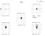
- the spot diagram is a diffuse pattern where after a plurality of lights passes through the optical system, intersection points of the lights emitted from a point and an image surface are not concentrated at a same point due to aberration and spread over in a certain range, and the diffuse pattern is used for evaluating imaging quality of the projection optical system.
- a maximum value of image points in the spot diagram corresponds to a maximum field of view, and the maximum value of image points in the spot diagram is less than 8.703 mm.
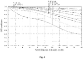
- the modulation transfer function refers to a relation between a modulation degree and the number of line pair per millimeter in an image and is used for evaluating ability to restore scenery details.
- the folded optical path system is of a single-lens structure
- the compensating lens is of a double-glued spherical lens structure
- optical system design data is shown in Table 2 below: Table 2 Type Surface number Surface type Curvature Thickness Material Dimensional radius Cone coefficient ⁇ 4 Object surface Aspherical Infinity Infinity 3 0 Diaphragm 30 Aspherical Infinity 10 14.58 0 Folded optical path system Fourth surface 22 Aspherical 21.15 4.39 E48R 14.58 -1 6.12E-06 Third surface 21 Aspherical 24.81 11.78 14.58 -3.27 5.52E-06 Compensating lens set Sixth surface 52 Spherical -100 1.99 E48R 10.42 Fifth surface 51 Spherical -83.51 0 10.42 Second surface 42 Spherical -83.51 1.99 PMMA 10.42 First surface 41 Spherical -58.74 1 10.42 Image surface Spherical Infinity 9.09 0
- parameters of the folded optical path system are as follows:
- a maximum field of view of the folded optical path system is 70 degrees, and a system length of the folded optical path system is less than 13 mm, the system length of the folded optical path system referring to a distance from the display unit 10 to a side surface, away from the display unit 10, of the folded optical path system.
- a lens diameter of the folded optical path system is less than 40 mm, an optical transfer function value of the folded optical path system at a frequency of 201 p/mm is greater than or equal to 0.5, a system focal length of the folded optical path system is 16.19 mm, and SPHA of the folded optical path system is 0.27.
- the spot diagram is a diffuse pattern where after a plurality of lights passes through the optical system, intersection points of the lights emitted from a point and an image surface are not concentrated at a same point due to aberration and spread over in a certain range, and the diffuse pattern is used for evaluating imaging quality of the projection optical system.
- a maximum value of image points in the spot diagram corresponds to a maximum field of view, and the maximum value of image points in the spot diagram is less than 8.990 mm.
- the MTF refers to a relation between a modulation degree and the number of line pair per millimeter in an image and is used for evaluating ability to restore scenery details.
- the folded optical path system is of a single-lens structure
- the compensating lens is a separated spherical lens combination
- optical system design data is shown in Table 3 below: Table 3 Type Surface number Surface type Curvature Thickness Material Dimensional radius Cone coefficient ⁇ 4 Object surface Aspherical Infinity Infinity 3 0 Diaphragm 30 Aspherical Infinity 10 14.58 0 Folded optical path system Fourth surface 22 Aspherical 21.15 4.39 E48R 14.58 -1 6.12E-06 Third surface 21 Aspherical 24.81 8.52 14.58 -3.27 5.52E-06 Compensating lens set Sixth surface 52 Spherical -625.87 5.13 E48R 12.94 Fifth surface 51 Spherical -34.97 3.96 12.32 Second surface 42 Spherical -18.89 4.01 PMMA 10.13 First surface 41 Spherical -33.43 1 9.64 Image surface Spherical Infinity 8.96 0
- parameters of the folded optical path system are as follows:
- a maximum field of view of the folded optical path system is 70 degrees, and a system length of the folded optical path system is less than 13 mm, the system length of the folded optical path system referring to a distance from the display unit 10 to a side surface, away from the display unit 10, of the folded optical path system.
- a lens diameter of the folded optical path system is less than 40 mm, an optical transfer function value of the folded optical path system at a frequency of 201 p/mm is greater than or equal to 0.5, a system focal length of the folded optical path system is 16.19 mm, and SPHA of the folded optical path system is 0.27.
- the spot diagram is a diffuse pattern where after a plurality of lights passes through the optical system, intersection points of the lights emitted from a point and an image surface are not concentrated at a same point due to aberration and spread over in a certain range, and the diffuse pattern is used for evaluating imaging quality of the projection optical system.
- a maximum value of image points in the spot diagram corresponds to a maximum field of view, and the maximum value of image points in the spot diagram is 8.936 mm.
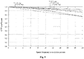
- the MTF refers to a relation between a modulation degree and the number of line pair per millimeter in an image and is used for evaluating ability to restore scenery details.
- the folded optical path system is of a single-lens structure
- the compensating lens is of a double-glued aspherical lens structure
- optical system design data is shown in Table 4 below: Table 4 Type Surface number Surface type Curvature Thickness Material Dimensional radius Cone coefficient ⁇ 4 Object surface Aspherical Infinity Infinity 3 0 Diaphragm 30 Aspherical Infinity 10 14.58 0 Folded optical path system Fourth surface 22 Aspherical 21.15 4.39 E48R 14.58 -1 6.12E-06 Third surface 21 Aspherical 24.81 8.52 14.58 -3.27 5.52E-06 Compensating lens set Sixth surface 52 Aspherical -30.06 2.92 E48R 12.94 -9.73 2.97E-05 Fifth surface 51 Aspherical -10.55 0 12.02 -59.99 7.59E-05 Second surface 42 Aspherical -10.55 4 PMMA 12.02 -59.99 7.59E-05 First surface 41 Aspher
- parameters of the folded optical path system are as follows:
- a maximum field of view of the folded optical path system is 70 degrees, and a system length of the folded optical path system is less than 13 mm, the system length of the folded optical path system referring to a distance from the display unit 10 to a side surface, away from the display unit 10, of the folded optical path system.
- a lens diameter of the folded optical path system is less than 40 mm, an optical transfer function value of the folded optical path system at a frequency of 201 p/mm is greater than or equal to 0.5, a system focal length of the folded optical path system is 16.19 mm, and SPHA of the folded optical path system is 0.27.
- Y is a center height of a lens surface
- Z is a displacement value of the aspherical structure from the optical axis by taking a surface vertex as the reference at a position with a height Y in the optical axis direction
- C is a curvature radius of a vertex of the aspherical surface
- K is a cone coefficient
- ⁇ i represents an aspherical coefficient at the 1st time.
- Y is a center height of a lens surface
- Z is a displacement value of the aspherical structure from the optical axis by taking a surface vertex as the reference at a position with a height Y in the optical axis direction
- C is a curvature radius of a vertex of the aspherical surface
- K is a cone coefficient
- ⁇ i represents an aspherical coefficient at the 1st time.
- the spot diagram is a diffuse pattern where after a plurality of lights passes through the optical system, intersection points of the lights emitted from a point and an image surface are not concentrated at a same point due to aberration and spread over in a certain range, and the diffuse pattern is used for evaluating imaging quality of the projection optical system.
- a maximum value of image points in the spot diagram corresponds to a maximum field of view, and the maximum value of image points in the spot diagram is 8.782 mm.
- the MTF refers to a relation between a modulation degree and the number of line pair per millimeter in an image and is used for evaluating ability to restore scenery details.
- the folded optical path system is of a single-lens structure
- the compensating lens is a separated aspherical lens combination
- optical system design data is shown in Table 5 below: Table 5 Type Surface number Surface type Curvature Thickness Material Dimensional radius Cone coefficient ⁇ 4 Object surface Aspherical Infinity Infinity 3 0 Diaphragm 30 Aspherical Infinity 10 14.58 0
- Folded optical path system Fourth surface 22 Aspherical 21.15 4.39 E48R 14.58 -1 6.12E-06 Third surface 21 Aspherical 24.81 8.52 14.58 -3.27 5.52E-06
- parameters of the folded optical path system are as follows:
- a maximum field of view of the folded optical path system is 70 degrees, and a system length of the folded optical path system is less than 13 mm, the system length of the folded optical path system referring to a distance from the display unit 10 to a side surface, away from the display unit 10, of the folded optical path system.
- a lens diameter of the folded optical path system is less than 40 mm, an optical transfer function value of the folded optical path system at a frequency of 201 p/mm is greater than or equal to 0.5, a system focal length of the folded optical path system is 16.19 mm, and SPHA of the folded optical path system is 0.27.
- Y is a center height of a lens surface
- Z is a displacement value of the aspherical structure from the optical axis by taking a surface vertex as the reference at a position with a height Y in the optical axis direction
- C is a curvature radius of a vertex of the aspherical surface
- K is a cone coefficient
- ⁇ i represents an aspherical coefficient at the 1st time.
- Y is a center height of a lens surface
- Z is a displacement value of the aspherical structure from the optical axis by taking a surface vertex as the reference at a position with a height Y in the optical axis direction
- C is a curvature radius of a vertex of the aspherical surface
- K is a cone coefficient
- ⁇ i represents an aspherical coefficient at the 1st time.
- the spot diagram is a diffuse pattern where after a plurality of lights passes through the optical system, intersection points of the lights emitted from a point and an image surface are not concentrated at a same point due to aberration and spread over in a certain range, and the diffuse pattern is used for evaluating imaging quality of the projection optical system.
- a maximum value of image points in the spot diagram corresponds to a maximum field of view, and the maximum value of image points in the spot diagram is 8.991 mm.
- the MTF refers to a relation between a modulation degree and the number of line pair per millimeter in an image and is used for evaluating ability to restore scenery details.
- the present invention further provides a virtual reality apparatus, the virtual reality apparatus includes the optical system of any one of the above embodiments, a specific structure of the optical system refers to the above embodiments, and since the optical system uses all the technical solutions of all the embodiments, all the beneficial effects brought by the technical solutions of the embodiments are at least achieved and are not repeated here.
Landscapes
- Physics & Mathematics (AREA)
- General Physics & Mathematics (AREA)
- Optics & Photonics (AREA)
- Engineering & Computer Science (AREA)
- Computer Graphics (AREA)
- Computer Hardware Design (AREA)
- General Engineering & Computer Science (AREA)
- Software Systems (AREA)
- Theoretical Computer Science (AREA)
- Lenses (AREA)
Abstract
Description
- The present invention relates to the technical field of optical imaging, in particular to a compensating lens set and a virtual reality apparatus with the same.
- In the prior art, the folded optical path system is usually used for achieving the light weight of the virtual reality apparatus in an optical path folding manner. Existing virtual reality apparatus adopting a folded optical path system typically lack optical compensation corresponding to its size reduction, leading to large aberration of a folded optical path system which causes distortion or deformation of an image observed by a user and brings negative influences on user experience of the virtual reality apparatus.
- The present invention provides a compensating lens set and a virtual reality apparatus with the same, so as to solve prior art problems relating to large aberration of a folded optical path system which causes distortion or deformation of an image observed by a user and brings negative influences on user experience of the virtual reality apparatus.
- For achieving the above objective, the present invention provides a compensating lens set. The compensating lens set is applied to a folded optical path system, where the folded optical path system sequentially includes, in an optical axis direction, a display unit, a first lens set and a diaphragm;
- the compensating lens set is arranged between the first lens set and the display unit, the compensating lens set including a first compensating lens, the first compensating lens including a first surface close to the display unit and a second surface away from the display unit, and the compensating lens set being configured to eliminate spherical aberration of the folded optical path system;
- the first lens set includes a third surface close to the display unit and a fourth surface away from the display unit; wherein incident light emitted by the display unit are reflected by the third surface and the fourth surface; and wherein
- the incident light enters the first compensating lens from the first surface, is emitted out of the first compensating lens from the second surface, passes through the first lens set, and then is transmitted to the diaphragm.
- Optionally, the first surface and the second surface are aspherical structures.
- Optionally, the compensating lens set further includes a second compensating lens, the second compensating lens being arranged between the first compensating lens and the first lens set, and the second compensating lens being provided with a fifth surface close to the first compensating lens and a sixth surface away from the first compensating lens.
- Optionally, the first surface, the second surface, the fifth surface and the sixth surface are all spherical surfaces, and a refractive power of the compensating lens set is the opposite of that of the first lens set.
- Optionally, the first compensating lens and the second compensating lens are separated from each other or connected with each other by glue-bonding or tight-lock coupling.
- Optionally, the first surface, the second surface, the fifth surface and the sixth surface are all aspherical structures.
- Optionally, a distance from a center of the display unit to a center of the fourth surface is less than or equal to 25 mm.
- Optionally, the compensating lens set is made of an optical plastic material.
- For achieving the above objective, the present application provides a virtual reality apparatus. The virtual reality apparatus includes a folded optical path system and a compensating lens set, where the compensating lens set is the compensating lens set of any one of above implementation modes.
- In the technical solution provided in the present application, the compensating lens set is applied to a folded optical path system, wherein: the folded optical path system includes a display unit, a first lens set and a diaphragm, and the first lens set includes a third surface close to the display unit and a fourth surface far away from the display unit, such that an incident light emitted by the display unit is reflected by the third surface and the fourth surface; the incident light emitted by the display unit enters the first compensating lens from the first surface, is emitted out of the first compensating lens from the second surface, passes through the first lens set, and then is transmitted to the diaphragm. With the combination of the compensating lens and the folded optical path system, spherical aberration of the folded optical path system is reduced under the condition that a total length of the folded optical path system is not influenced, so as to solve prior art problems relating to large spherical aberration of a folded optical path system which causes distortion or deformation of an image observed by a user and brings negative influences on user experience of the virtual reality apparatus.
- In order to more clearly illustrate technical solutions in the embodiments of the present invention or in the prior art, a brief introduction to the accompanying drawings required for the description of the embodiments or the prior art will be provided below. Obviously, the accompanying drawings in the following description are only some of the embodiments of the present invention, and those of ordinary skill in the art would also be able to derive other drawings from structures shown by these drawings without making creative efforts.
-
Fig. 1 is a schematic diagram of an optical structure of Embodiment 1 of a compensating lens set of the present invention; -
Fig. 2 is a spot diagram of Embodiment 1 of the compensating lens set of the present invention; -
Fig. 3 is a diagram of a modulation transfer function of Embodiment 1 of the compensating lens set of the present invention; -
Fig. 4 is a schematic diagram of an optical structure ofEmbodiment 2 of the compensating lens set of the present invention; -
Fig. 5 is a spot diagram ofEmbodiment 2 of the compensating lens set of the present invention; -
Fig. 6 is a diagram of a modulation transfer function ofEmbodiment 2 of the compensating lens set of the present invention; -
Fig. 7 is a schematic diagram of an optical structure of Embodiment 3 of the compensating lens set of the present invention; -
Fig. 8 is a spot diagram of Embodiment 3 of the compensating lens set of the present invention; -
Fig. 9 is a diagram of a modulation transfer function of Embodiment 3 of the compensating lens set of the present invention; -
Fig. 10 is a schematic diagram of an optical structure ofEmbodiment 4 of the compensating lens set of the present invention; -
Fig. 11 is a spot diagram ofEmbodiment 4 of the compensating lens set of the present invention; -
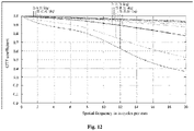
Fig. 12 is a diagram of a modulation transfer function ofEmbodiment 4 of the compensating lens set of the present invention; -
Fig. 13 is a schematic diagram of an optical structure of Embodiment 5 of the compensating lens set of the present invention; -
Fig. 14 is a spot diagram of Embodiment 5 of the compensating lens set of the present invention; and -
Fig. 15 is a diagram of a modulation transfer function of Embodiment 5 of the compensating lens set of the present invention. - Brief description of the reference numbers:
Reference number Name Reference number Name 10 Display unit 21 Third surface 20 First lens set 22 Fourth surface 30 Diaphragm 50 Second compensating lens 40 First compensating lens 51 Fifth surface 41 First surface 52 Sixth surface 42 Second surface - Achievement of the objectives, functional features and advantages of the present invention will be further described in conjunction with the embodiments and with reference to the accompanying drawings.
- The technical solutions of embodiments of the present invention will be described below clearly and comprehensively in conjunction with accompanying drawings of the embodiments of the present invention. Apparently, the embodiments described are merely some embodiments rather than all embodiments of the present invention. Based on the embodiments of the present invention, other various embodiments obtained by those of ordinary skill in the art without making creative efforts fall within the scope of protection of the present invention.
- It should be noted that all directionality indications (for example, up, down, left, right, front, back,...) in embodiments of the present invention are merely used to explain relative positional relations, motion conditions, etc. between components in a certain specific posture (as shown in the accompanying drawings), and under the condition that the specific posture changes, the directionality indications change accordingly.
- In addition, descriptions of "first", "second", and so forth in the embodiments of the present invention are for descriptive purposes only and are not to be construed as indicating or implying their relative importance or implicitly specifying the number of indicated technical features. Thus, features defined with "first" and "second" may explicitly or implicitly include at least one of the features. In the description of the present invention, "plurality" means two or more, for example, two, three, etc., unless expressly specified otherwise.
- In the present invention, unless expressly specified otherwise, the terms "connect", "fix", etc. are to be construed broadly, for example, "fix" may be fixedly connected, or detachably connected, or integrally formed, may be mechanically connected, or electrically connected, may be direct connected or indirect connected via an intermediary medium, or may be a communication between two elements or an interworking relation between two elements, unless expressly defined otherwise. The specific meanings of the above terms in the present invention may be understood on a case-by-case basis for those of ordinary skill in the art.
- In addition, the technical solutions of the embodiments in the present invention may be combined with one another, which must be based on the achievement by the ordinary skill in the art, and when the combinations of the technical solutions contradict each other or cannot be achieved, it should be considered that the combinations of the technical solutions do not exist and are not within the scope of protection claimed in the present invention.
- The present invention provides a compensating lens set and a virtual reality apparatus with the same.
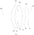
- With reference to
Fig. 1 , the compensating lens set is applied to a folded optical path system, where the folded optical path system sequentially includes, in an optical axis direction, adisplay unit 10, a first lens set 20 and adiaphragm 30; - the compensating lens set is arranged between the first lens set 20 and the
display unit 10, the compensating lens set includes a first compensatinglens 40, the first compensatinglens 40 including afirst surface 41 close to thedisplay unit 10 and asecond surface 42 away from thedisplay unit 10, and the compensating lens set is configured to eliminate spherical aberration of the folded optical path system; - the
first lens set 20 includes athird surface 21 close to thedisplay unit 10 and afourth surface 22 away from thedisplay unit 10; incident light emitted by thedisplay unit 10 are reflected by thethird surface 21 and thefourth surface 22; and - the incident light enters the first compensating
lens 40 from thefirst surface 41, is emitted out of the first compensatinglens 40 from thesecond surface 42, passes through the first lens set 20, and then is transmitted to thediaphragm 30. - In the technical solution provided in the present application, the compensating lens set is applied to a folded optical path system, where the folded optical path system includes a
display unit 10, a first lens set 20 and adiaphragm 30, and the first lens set 20 includes athird surface 21 close to thedisplay unit 10 and afourth surface 22 far away from thedisplay unit 10, such that incident light emitted by thedisplay unit 10 is reflected by thethird surface 21 and thefourth surface 22; and the incident light emitted by thedisplay unit 10 enters the first compensatinglens 40 from thefirst surface 41, is emitted out of the first compensatinglens 40 from thesecond surface 42, passes through the first lens set 20, and then is transmitted to thediaphragm 30. By means of the combined use of the compensating lens and the folded optical path system, spherical aberration of the folded optical path system is reduced under the condition that a total length of the folded optical path system is not influenced, so as to solve prior art problems relating to large aberration of a folded optical path system which causes distortion or deformation of an image observed by a user and brings negative influences on user experience of the virtual reality apparatus. - It will be appreciated that, in addition to eliminating a spherical aberration of the folded optical path system, the compensating lens set may eliminate or reduce other aberration of the folded optical path system to an extent feasible for optical design, where the aberration includes but is not limited to coma, astigmatism, field curvature, distortion, and other imaging defects influencing optical imaging.
- In a preferred implementation mode, the
first surface 41 and thesecond surface 42 are aspherical structures. Specifically, compared with a spherical structure, the aspherical structure may effectively reduce the spherical aberration and distortion of the optical system, so as to reduce the number of lens in the optical system and a size of the lens. - In some optional implementation modes, the compensating lens set further includes a second compensating
lens 50, specifically, the second compensatinglens 50 is arranged between the first compensatinglens 40 and the first lens set 20, and the second compensatinglens 50 is provided with afifth surface 51 close to the first compensatinglens 40 and asixth surface 52 away from the first compensatinglens 40. The incident light emitted by thedisplay unit 10 enters the first compensatinglens 40 from thefirst surface 41, is emitted out of the first compensatinglens 40 from thesecond surface 42, enters the second compensatinglens 50 by means of thefifth surface 51, is emitted out of the second compensatinglens 50 from thesixth surface 52, and enters the folded light path system. The spherical aberration of the folded optical path system is further reduced by means of the combined use of the first compensatinglens 40 and the second compensatinglens 50. - In a preferred implementation mode, the
first surface 41, thesecond surface 42, thefifth surface 51 and thesixth surface 52 are all spherical surfaces, and a refractive power of the compensating lens set is the opposite of that of the first lens set 20. The refractive power is a difference between a convergence degree of an image-side light beam and a convergence degree of an object-side light beam, and is used for representing refraction capability of the optical system one the incident parallel light beam. - In some optional implementation modes, the first compensating
lens 40 and the second compensatinglens 50 are separated from each other or connected with each other by glue-bonding or tight-lock coupling. - In some optional implementation modes, the
first surface 41, thesecond surface 42, thefifth surface 51 and thesixth surface 52 are all aspherical surfaces. Specifically, compared with a spherical structure, the aspherical structure may effectively reduce the spherical aberration and distortion of the optical system, so as to reduce the number of lens in the optical system and a size of the lens. - In a preferred implementation mode, a distance from a center of the
display unit 10 to a center of the fourth surface is less than or equal to 25 mm. - In some optional implementation modes, the compensating lens set is made of an optical plastic material. Specifically, compared with optical glass, the optical plastic has the advantages of good plastic forming process feature, light weight, low cost, etc., and therefore a size and the cost of the compensating lens set may be effectively reduced.
- With reference to
Figs 1-3 , in Embodiment 1, the folded optical path system is of a single-lens structure, the compensating lens is of a single-lens structure, and optical system design data is shown in Table 1 below:Table 1 Type Surface number Surface type Curvature Thickness Material Dimensional radius Cone coefficient α4 Object surface Aspherical Infinity Infinity 3 0 Diaphragm 30Aspherical Infinity 10 14.58 0 Folded optical path system Fourth surface 22 Aspherical 21.15 4.39 E48R 14.58 -1 6.12 E-06 Third surface 21 Aspherical 24.81 8.52 14.58 -3.27 5.52E-06 Compensating lens set Second surface 42Aspherical 114.87 3.78 E48R 11.08 20 1.22E-05 First surface 41 Aspherical -118.56 4.05 11.08 -20 4.98E-05 Image surface Spherical Infinity 8.79 0 - In Embodiment 1, parameters of the folded optical path system are as follows:
- A maximum field of view of the folded optical path system is 70 degrees, and a system length of the folded optical path system is less than 13 mm, the system length of the folded optical path system referring to a distance from the
display unit 10 to a side surface, away from thedisplay unit 10, of the folded optical path system. A lens diameter of the folded optical path system is less than 40 mm, an optical transfer function value of the folded optical path system at a frequency of 201 p/mm is greater than or equal to 0.5, a system focal length of the folded optical path system is 16.19 mm, and spherical aberration (SPHA) of the folded optical path system is 0.27. - The
first surface 41 and thesecond surface 42 may be an even-order aspherical structure, where an even-order aspherical surface satisfies the following relation:

where Y is a center height of a lens surface, Z is a displacement value of the aspherical structure from the optical axis by taking a surface vertex as the reference at a position with a height Y in the optical axis direction, C is a curvature radius of a vertex of the aspherical surface, and K is a cone coefficient; and αi represents an aspherical coefficient at the 1st time. - In another embodiment, the
second surface 42 and thefourth surface 22 may also be odd-order aspherical structures, where an odd-order aspherical surface satisfies the following relation:

where Y is a center height of a lens surface, Z is a displacement value of the aspherical structure from the optical axis by taking a surface vertex as the reference at a position with a height Y in the optical axis direction, C is a curvature radius of a vertex of the aspherical surface, and K is a cone coefficient; and βi represents an aspherical coefficient at the 1st time. - With reference to
Fig. 2 , a spot diagram of Embodiment 1 is shown. The spot diagram is a diffuse pattern where after a plurality of lights passes through the optical system, intersection points of the lights emitted from a point and an image surface are not concentrated at a same point due to aberration and spread over in a certain range, and the diffuse pattern is used for evaluating imaging quality of the projection optical system. In Embodiment 1, a maximum value of image points in the spot diagram corresponds to a maximum field of view, and the maximum value of image points in the spot diagram is less than 8.703 mm. - With reference to
Fig. 3 , a diagram of a modulation transfer function of Embodiment 1 is shown. The modulation transfer function (MTF) refers to a relation between a modulation degree and the number of line pair per millimeter in an image and is used for evaluating ability to restore scenery details. - With reference to
Figs 4-6 , inEmbodiment 2, the folded optical path system is of a single-lens structure, the compensating lens is of a double-glued spherical lens structure, and optical system design data is shown in Table 2 below:Table 2 Type Surface number Surface type Curvature Thickness Material Dimensional radius Cone coefficient α4 Object surface Aspherical Infinity Infinity 3 0 Diaphragm 30Aspherical Infinity 10 14.58 0 Folded optical path system Fourth surface 22 Aspherical 21.15 4.39 E48R 14.58 -1 6.12 E-06 Third surface 21 Aspherical 24.81 11.78 14.58 -3.27 5.52E-06 Compensating lens set Sixth surface 52Spherical -100 1.99 E48R 10.42 Fifth surface 51Spherical -83.51 0 10.42 Second surface 42Spherical -83.51 1.99 PMMA 10.42 First surface 41Spherical -58.74 1 10.42 Image surface Spherical Infinity 9.09 0 - In
Embodiment 2, parameters of the folded optical path system are as follows: - A maximum field of view of the folded optical path system is 70 degrees, and a system length of the folded optical path system is less than 13 mm, the system length of the folded optical path system referring to a distance from the
display unit 10 to a side surface, away from thedisplay unit 10, of the folded optical path system. A lens diameter of the folded optical path system is less than 40 mm, an optical transfer function value of the folded optical path system at a frequency of 201 p/mm is greater than or equal to 0.5, a system focal length of the folded optical path system is 16.19 mm, and SPHA of the folded optical path system is 0.27. - With reference to
Fig. 5 , a spot diagram ofEmbodiment 2 is shown. The spot diagram is a diffuse pattern where after a plurality of lights passes through the optical system, intersection points of the lights emitted from a point and an image surface are not concentrated at a same point due to aberration and spread over in a certain range, and the diffuse pattern is used for evaluating imaging quality of the projection optical system. InEmbodiment 2, a maximum value of image points in the spot diagram corresponds to a maximum field of view, and the maximum value of image points in the spot diagram is less than 8.990 mm. - With reference to
Fig. 6 , a diagram of a MTF ofEmbodiment 2 is shown. The MTF refers to a relation between a modulation degree and the number of line pair per millimeter in an image and is used for evaluating ability to restore scenery details. - With reference to
Figs 7-9 , in Embodiment 3, the folded optical path system is of a single-lens structure, the compensating lens is a separated spherical lens combination;, and optical system design data is shown in Table 3 below:Table 3 Type Surface number Surface type Curvature Thickness Material Dimensional radius Cone coefficient α4 Object surface Aspherical Infinity Infinity 3 0 Diaphragm 30Aspherical Infinity 10 14.58 0 Folded optical path system Fourth surface 22 Aspherical 21.15 4.39 E48R 14.58 -1 6.12 E-06 Third surface 21 Aspherical 24.81 8.52 14.58 -3.27 5.52E-06 Compensating lens set Sixth surface 52Spherical -625.87 5.13 E48R 12.94 Fifth surface 51Spherical -34.97 3.96 12.32 Second surface 42Spherical -18.89 4.01 PMMA 10.13 First surface 41Spherical -33.43 1 9.64 Image surface Spherical Infinity 8.96 0 - In Embodiment 3, parameters of the folded optical path system are as follows:
- A maximum field of view of the folded optical path system is 70 degrees, and a system length of the folded optical path system is less than 13 mm, the system length of the folded optical path system referring to a distance from the
display unit 10 to a side surface, away from thedisplay unit 10, of the folded optical path system. A lens diameter of the folded optical path system is less than 40 mm, an optical transfer function value of the folded optical path system at a frequency of 201 p/mm is greater than or equal to 0.5, a system focal length of the folded optical path system is 16.19 mm, and SPHA of the folded optical path system is 0.27. - With reference to
Fig. 8 , a spot diagram of Embodiment 3 is shown. The spot diagram is a diffuse pattern where after a plurality of lights passes through the optical system, intersection points of the lights emitted from a point and an image surface are not concentrated at a same point due to aberration and spread over in a certain range, and the diffuse pattern is used for evaluating imaging quality of the projection optical system. In Embodiment 3, a maximum value of image points in the spot diagram corresponds to a maximum field of view, and the maximum value of image points in the spot diagram is 8.936 mm. - With reference to
Fig. 9 , a diagram of a MTF of Embodiment 3 is shown. The MTF refers to a relation between a modulation degree and the number of line pair per millimeter in an image and is used for evaluating ability to restore scenery details. - With reference to
Figs 10-12 , inEmbodiment 4, the folded optical path system is of a single-lens structure, the compensating lens is of a double-glued aspherical lens structure, and optical system design data is shown in Table 4 below:Table 4 Type Surface number Surface type Curvature Thickness Material Dimensional radius Cone coefficient α4 Object surface Aspherical Infinity Infinity 3 0 Diaphragm 30Aspherical Infinity 10 14.58 0 Folded optical path system Fourth surface 22 Aspherical 21.15 4.39 E48R 14.58 -1 6.12 E-06 Third surface 21 Aspherical 24.81 8.52 14.58 -3.27 5.52E-06 Compensating lens set Sixth surface 52Aspherical -30.06 2.92 E48R 12.94 -9.73 2.97 E-05 Fifth surface 51 Aspherical -10.55 0 12.02 -59.99 7.59 E-05 Second surface 42 Aspherical -10.55 4 PMMA 12.02 -59.99 7.59E-05 First surface 41 Aspherical -8.71 5.37 12.94 -4.78 6.01E-05 Image surface Spherical Infinity 8.84 0 - In
Embodiment 4, parameters of the folded optical path system are as follows: - A maximum field of view of the folded optical path system is 70 degrees, and a system length of the folded optical path system is less than 13 mm, the system length of the folded optical path system referring to a distance from the
display unit 10 to a side surface, away from thedisplay unit 10, of the folded optical path system. A lens diameter of the folded optical path system is less than 40 mm, an optical transfer function value of the folded optical path system at a frequency of 201 p/mm is greater than or equal to 0.5, a system focal length of the folded optical path system is 16.19 mm, and SPHA of the folded optical path system is 0.27. - The
first surface 41 and thesecond surface 42 may be an even-order aspherical structure, where an even-order aspherical surface satisfies the following relation:

where Y is a center height of a lens surface, Z is a displacement value of the aspherical structure from the optical axis by taking a surface vertex as the reference at a position with a height Y in the optical axis direction, C is a curvature radius of a vertex of the aspherical surface, and K is a cone coefficient; and αi represents an aspherical coefficient at the 1st time. - In another embodiment, the
second surface 42 and thefourth surface 22 may also be odd-order aspherical structures, where an odd-order aspherical surface satisfies the following relation:

where Y is a center height of a lens surface, Z is a displacement value of the aspherical structure from the optical axis by taking a surface vertex as the reference at a position with a height Y in the optical axis direction, C is a curvature radius of a vertex of the aspherical surface, and K is a cone coefficient; and βi represents an aspherical coefficient at the 1st time. - With reference to
Fig. 11 , a spot diagram ofEmbodiment 4 is shown. The spot diagram is a diffuse pattern where after a plurality of lights passes through the optical system, intersection points of the lights emitted from a point and an image surface are not concentrated at a same point due to aberration and spread over in a certain range, and the diffuse pattern is used for evaluating imaging quality of the projection optical system. InEmbodiment 4, a maximum value of image points in the spot diagram corresponds to a maximum field of view, and the maximum value of image points in the spot diagram is 8.782 mm. - With reference to
Fig. 12 , a diagram of a MTF ofEmbodiment 4 is shown. The MTF refers to a relation between a modulation degree and the number of line pair per millimeter in an image and is used for evaluating ability to restore scenery details. - With reference to
Figs 13-15 , in Embodiment 5, the folded optical path system is of a single-lens structure, the compensating lens is a separated aspherical lens combination, and optical system design data is shown in Table 5 below:Table 5 Type Surface number Surface type Curvature Thickness Material Dimensional radius Cone coefficient α4 Object surface Aspherical Infinity Infinity 3 0 Diaphragm 30Aspherical Infinity 10 14.58 0 Folded optical path system Fourth surface 22 Aspherical 21.15 4.39 E48R 14.58 -1 6.12 E-06 Third surface 21 Aspherical 24.81 8.52 14.58 -3.27 5.52E-06 Compensating lens set Sixth surface 52Spherical 47.23 2.00 E48R 12.94 Fifth surface 51Spherical 37.93 3.39 11.48 Second surface 42Spherical -42.87 4.0 PMMA 11.34 First surface 41Spherical -15.77 6.26 11.05 Image surface Spherical Infinity 8.99 0 - In Embodiment 5, parameters of the folded optical path system are as follows:
- A maximum field of view of the folded optical path system is 70 degrees, and a system length of the folded optical path system is less than 13 mm, the system length of the folded optical path system referring to a distance from the
display unit 10 to a side surface, away from thedisplay unit 10, of the folded optical path system. A lens diameter of the folded optical path system is less than 40 mm, an optical transfer function value of the folded optical path system at a frequency of 201 p/mm is greater than or equal to 0.5, a system focal length of the folded optical path system is 16.19 mm, and SPHA of the folded optical path system is 0.27. - The
first surface 41 and thesecond surface 42 may be an even-order aspherical structure, where an even-order aspherical surface satisfies the following relation:

where Y is a center height of a lens surface, Z is a displacement value of the aspherical structure from the optical axis by taking a surface vertex as the reference at a position with a height Y in the optical axis direction, C is a curvature radius of a vertex of the aspherical surface, and K is a cone coefficient; and αi represents an aspherical coefficient at the 1st time. - In another embodiment, the
second surface 42 and thefourth surface 22 may also be odd-order aspherical structures, where an odd-order aspherical surface satisfies the following relation:

where Y is a center height of a lens surface, Z is a displacement value of the aspherical structure from the optical axis by taking a surface vertex as the reference at a position with a height Y in the optical axis direction, C is a curvature radius of a vertex of the aspherical surface, and K is a cone coefficient; and βi represents an aspherical coefficient at the 1st time. - With reference to
Fig. 14 , a spot diagram of Embodiment 5 is shown. The spot diagram is a diffuse pattern where after a plurality of lights passes through the optical system, intersection points of the lights emitted from a point and an image surface are not concentrated at a same point due to aberration and spread over in a certain range, and the diffuse pattern is used for evaluating imaging quality of the projection optical system. In Embodiment 5, a maximum value of image points in the spot diagram corresponds to a maximum field of view, and the maximum value of image points in the spot diagram is 8.991 mm. - With reference to
Fig. 15 , a diagram of a MTF of Embodiment 5 is shown. The MTF refers to a relation between a modulation degree and the number of line pair per millimeter in an image and is used for evaluating ability to restore scenery details. - The present invention further provides a virtual reality apparatus, the virtual reality apparatus includes the optical system of any one of the above embodiments, a specific structure of the optical system refers to the above embodiments, and since the optical system uses all the technical solutions of all the embodiments, all the beneficial effects brought by the technical solutions of the embodiments are at least achieved and are not repeated here.
- The above are only preferred embodiments of the present invention and do not limit the patentable scope of the present invention, and equivalent structural transformation made by utilizing the contents of the specification and accompanying drawings of the present invention or direct/indirect application in other related technical fields fall within the patentable scope of protection of the present invention under the inventive concept of the present invention.
Claims (9)
- A compensating lens set, characterized in that the compensating lens set is applied to a folded optical path system, the folded optical path system sequentially comprising, in an optical axis direction, a display unit, a first lens set and a diaphragm;the compensating lens set is arranged between the first lens set and the display unit, the compensating lens set comprising a first compensating lens, the first compensating lens comprising a first surface close to the display unit and a second surface away from the display unit, and the compensating lens set being configured to eliminate spherical aberration of the folded optical path system; andthe first lens set comprises a third surface close to the display unit and a fourth surface away from the display unit; wherein incident light emitted by the display unit are reflected by the third surface and the fourth surface; andwherein the incident light enters the first compensating lens from the first surface, is emitted out of the first compensating lens from the second surface, passes through the first lens set, and then is transmitted to the diaphragm.
- The compensating lens set of claim 1, wherein the first surface and the second surface are aspherical structures.
- The compensating lens set of claim 1, further comprising a second compensating lens, the second compensating lens being arranged between the first compensating lens and the first lens set, and the second compensating lens being provided with a fifth surface close to the first compensating lens and a sixth surface away from the first compensating lens.
- The compensating lens set of claim 3, wherein the first surface, the second surface, the fifth surface and the sixth surface are all spherical surfaces, and a refractive power of the compensating lens set is the opposite of that of the first lens set.
- The compensating lens set of claim 3, wherein the first compensating lens and the second compensating lens are separated from each other or connected with each other by glue-bonding or tight-lock coupling.
- The compensating lens set of claim 3, wherein the first surface, the second surface, the fifth surface and the sixth surface are all aspherical structures.
- The compensating lens set of any one of claims 1-6, wherein a distance from a center of the display unit to a center of the fourth surface is less than or equal to 25 mm.
- The compensating lens set of any one of claims 1-6, wherein the compensating lens set is made of an optical plastic material.
- A virtual reality apparatus, comprising:a folded optical path system, anda compensating lens set, wherein the compensating lens set is the compensating lens set of any one of claims 1-8.
Applications Claiming Priority (2)
| Application Number | Priority Date | Filing Date | Title |
|---|---|---|---|
| CN201910479424.3A CN110161696B (en) | 2019-06-03 | 2019-06-03 | Compensation lens group and virtual reality device having the same |
| PCT/CN2019/129179 WO2020244213A1 (en) | 2019-06-03 | 2019-12-27 | Compensation lens set and virtual reality device having same |
Publications (2)
| Publication Number | Publication Date |
|---|---|
| EP4024119A1 true EP4024119A1 (en) | 2022-07-06 |
| EP4024119A4 EP4024119A4 (en) | 2023-12-06 |
Family
ID=67627099
Family Applications (1)
| Application Number | Title | Priority Date | Filing Date |
|---|---|---|---|
| EP19931620.9A Pending EP4024119A4 (en) | 2019-06-03 | 2019-12-27 | COMPENSATION LENS SET AND DEVICE FOR VIRTUAL REALITY THEREFROM |
Country Status (4)
| Country | Link |
|---|---|
| US (1) | US12276787B2 (en) |
| EP (1) | EP4024119A4 (en) |
| CN (1) | CN110161696B (en) |
| WO (1) | WO2020244213A1 (en) |
Families Citing this family (1)
| Publication number | Priority date | Publication date | Assignee | Title |
|---|---|---|---|---|
| CN110161696B (en) * | 2019-06-03 | 2021-02-05 | 歌尔光学科技有限公司 | Compensation lens group and virtual reality device having the same |
Family Cites Families (38)
| Publication number | Priority date | Publication date | Assignee | Title |
|---|---|---|---|---|
| JP3382683B2 (en) * | 1993-10-22 | 2003-03-04 | オリンパス光学工業株式会社 | Concentric optical system |
| US5659430A (en) * | 1993-12-21 | 1997-08-19 | Olympus Optical Co., Ltd. | Visual display apparatus |
| JPH07261088A (en) * | 1994-03-18 | 1995-10-13 | Olympus Optical Co Ltd | Homocentric optical system |
| JP3441188B2 (en) * | 1994-10-07 | 2003-08-25 | オリンパス光学工業株式会社 | Optical system and visual display device |
| JPH08122642A (en) * | 1994-10-26 | 1996-05-17 | Olympus Optical Co Ltd | Optical system |
| JP2000241705A (en) * | 1999-02-23 | 2000-09-08 | Minolta Co Ltd | Video display optical system |
| JP2001142006A (en) * | 1999-11-16 | 2001-05-25 | Minolta Co Ltd | Eyepiece optical system and video display device |
| JP2002107655A (en) * | 2000-09-27 | 2002-04-10 | Minolta Co Ltd | Video display device |
| US7019909B2 (en) | 2001-11-14 | 2006-03-28 | Canon Kabushiki Kaisha | Optical system, image display apparatus, and image taking apparatus |
| CN1432841A (en) * | 2002-01-16 | 2003-07-30 | 深圳市东方景电子有限公司 | Optical system with high image quality for head display |
| US8456745B2 (en) * | 2010-05-12 | 2013-06-04 | Jill Weissman | Compact eyepiece using an imersed field lens |
| US8384999B1 (en) * | 2012-01-09 | 2013-02-26 | Cerr Limited | Optical modules |
| JP6111635B2 (en) * | 2012-02-24 | 2017-04-12 | セイコーエプソン株式会社 | Virtual image display device |
| CN103995355B (en) * | 2014-05-23 | 2016-06-01 | 北京理工大学 | The optical system of a kind of adjustable diopter for Helmet Mounted Display |
| WO2017039718A1 (en) * | 2015-09-03 | 2017-03-09 | 3M Innovative Properties Company | Magnifying device |
| US10422976B2 (en) * | 2016-02-26 | 2019-09-24 | Samsung Electronics Co., Ltd. | Aberration corrected optical system for near-eye displays |
| US10663745B2 (en) * | 2016-06-09 | 2020-05-26 | 3M Innovative Properties Company | Optical system |
| CN109313287B (en) * | 2016-06-09 | 2021-07-09 | 3M创新有限公司 | Display system and light guide |
| US10197802B2 (en) * | 2016-07-29 | 2019-02-05 | Intevac, Inc. | Biocular compact collimation apparatus |
| CN206224048U (en) * | 2016-08-31 | 2017-06-06 | 深圳超多维科技有限公司 | A kind of VR display devices and wear-type VR display devices |
| US11314097B2 (en) * | 2016-12-20 | 2022-04-26 | 3M Innovative Properties Company | Optical system |
| US10545347B2 (en) * | 2017-02-23 | 2020-01-28 | Google Llc | Compact eye tracking using folded display optics |
| US11156814B2 (en) * | 2017-03-31 | 2021-10-26 | 3M Innovative Properties Company | Optical system for displaying an object to a viewer |
| JP2020519964A (en) * | 2017-05-16 | 2020-07-02 | スリーエム イノベイティブ プロパティズ カンパニー | Optical system |
| CN207301485U (en) * | 2017-06-15 | 2018-05-01 | 北京海鲸科技有限公司 | A kind of eyepiece and wear display device |
| US20190018255A1 (en) * | 2017-07-11 | 2019-01-17 | Google Llc | Compact near-eye optical system including a refractive beam-splitting convex lens |
| JP7005207B2 (en) * | 2017-07-26 | 2022-01-21 | キヤノン株式会社 | Optical system, imaging device and projection device equipped with it |
| JP7361028B2 (en) * | 2017-10-27 | 2023-10-13 | スリーエム イノベイティブ プロパティズ カンパニー | optical system |
| US11054622B1 (en) * | 2017-11-20 | 2021-07-06 | Facebook Technologies, Llc | Folded viewing optics with an optical retarder on a simple surface |
| US11243397B2 (en) * | 2018-05-18 | 2022-02-08 | Facebook Technologies, Llc | Optical assembly with polarization volume holographic element |
| JP7154878B2 (en) * | 2018-08-22 | 2022-10-18 | キヤノン株式会社 | Observation optical system and observation device having the same |
| US10816804B2 (en) * | 2018-08-31 | 2020-10-27 | Google Llc | Near-eye display system with polarization-based optical path folding and variable focus catadioptric lens assembly |
| JP7183003B2 (en) * | 2018-11-16 | 2022-12-05 | キヤノン株式会社 | Image display device, eyepiece optical system, and eyepiece optical system manufacturing method |
| US10600352B1 (en) * | 2018-12-04 | 2020-03-24 | Facebook Technologies, Llc | Display device with a switchable window and see-through pancake lens assembly |
| JP7207986B2 (en) * | 2018-12-14 | 2023-01-18 | キヤノン株式会社 | Image display device and eyepiece optical system |
| US10996466B2 (en) * | 2019-02-05 | 2021-05-04 | Facebook Technologies, Llc | Waveplates on a curved surface and fabrication method thereof |
| US10890776B1 (en) * | 2019-02-19 | 2021-01-12 | Facebook Technologies, Llc | Pancake lens ghosting mitigation |
| CN110161696B (en) * | 2019-06-03 | 2021-02-05 | 歌尔光学科技有限公司 | Compensation lens group and virtual reality device having the same |
-
2019
- 2019-06-03 CN CN201910479424.3A patent/CN110161696B/en active Active
- 2019-12-27 EP EP19931620.9A patent/EP4024119A4/en active Pending
- 2019-12-27 WO PCT/CN2019/129179 patent/WO2020244213A1/en not_active Ceased
- 2019-12-27 US US17/616,257 patent/US12276787B2/en active Active
Also Published As
| Publication number | Publication date |
|---|---|
| EP4024119A4 (en) | 2023-12-06 |
| US20220252877A1 (en) | 2022-08-11 |
| WO2020244213A1 (en) | 2020-12-10 |
| US12276787B2 (en) | 2025-04-15 |
| CN110161696B (en) | 2021-02-05 |
| CN110161696A (en) | 2019-08-23 |
Similar Documents
| Publication | Publication Date | Title |
|---|---|---|
| US7782551B2 (en) | Wide-angle image pick-up lens system and vehicle with same | |
| KR102257641B1 (en) | Near field optical amplification module, glasses, helmet and virtual reality system | |
| EP4141515A1 (en) | Optical system and virtual reality device | |
| US10330914B2 (en) | Stereoscopic imaging optical system assembly, stereoscopic imaging apparatus, and endoscope | |
| US10746975B2 (en) | Objective lens for a still or film camera and method for selective damping of specific spatial frequency ranges of the modulation transfer function of such an objective lens | |
| EP3249446B1 (en) | Short-distance optical magnification module, glasses, helmet and vr system | |
| US10324292B2 (en) | Short range optical amplification module, spectacles, helmet and VR system | |
| KR102257640B1 (en) | Near field optical amplification module, glasses, helmet and virtual reality system | |
| CN107219637B (en) | Short-distance optical amplification module, glasses, helmet and VR system | |
| CN111766754B (en) | Optical system and projection device | |
| CN113934007A (en) | Optical module and head-mounted display device | |
| EP3906838A1 (en) | 4k laparoscope objective lens with 30° viewing angle | |
| US7755842B2 (en) | Anastigmatic anamorphic lens system | |
| CN105676477A (en) | Short distance optical magnification module, glasses, helmet and VR system | |
| EP2056150A1 (en) | Transmissive optical element and optical system using the same | |
| CN205562978U (en) | Short distance optical enlargement module, glasses, helmet and VR system | |
| CN205562979U (en) | Short distance optical enlargement module, glasses, helmet and VR system | |
| EP3702824B1 (en) | Head mounted display device with eyepiece | |
| US6712474B2 (en) | Projection lens and projector provided with the same | |
| US12276787B2 (en) | Compensating lens set and virtual reality apparatus with the same | |
| KR101404611B1 (en) | endoscope optical system | |
| US20220057704A1 (en) | Optical system and projection device | |
| US20230333364A1 (en) | Optical system | |
| CN102346290B (en) | Optical lens assembly | |
| CN112346213B (en) | Universal image transfer lens and optical device for prism compensation |
Legal Events
| Date | Code | Title | Description |
|---|---|---|---|
| STAA | Information on the status of an ep patent application or granted ep patent |
Free format text: STATUS: THE INTERNATIONAL PUBLICATION HAS BEEN MADE |
|
| PUAI | Public reference made under article 153(3) epc to a published international application that has entered the european phase |
Free format text: ORIGINAL CODE: 0009012 |
|
| STAA | Information on the status of an ep patent application or granted ep patent |
Free format text: STATUS: REQUEST FOR EXAMINATION WAS MADE |
|
| 17P | Request for examination filed |
Effective date: 20211202 |
|
| AK | Designated contracting states |
Kind code of ref document: A1 Designated state(s): AL AT BE BG CH CY CZ DE DK EE ES FI FR GB GR HR HU IE IS IT LI LT LU LV MC MK MT NL NO PL PT RO RS SE SI SK SM TR |
|
| DAV | Request for validation of the european patent (deleted) | ||
| DAX | Request for extension of the european patent (deleted) | ||
| RAP1 | Party data changed (applicant data changed or rights of an application transferred) |
Owner name: GOERTEK OPTICAL TECHNOLOGY CO., LTD. |
|
| A4 | Supplementary search report drawn up and despatched |
Effective date: 20231103 |
|
| RIC1 | Information provided on ipc code assigned before grant |
Ipc: G02B 13/18 20060101ALN20231027BHEP Ipc: G02B 27/00 20060101ALI20231027BHEP Ipc: G02B 13/06 20060101ALI20231027BHEP Ipc: G02B 27/01 20060101AFI20231027BHEP |
|
| STAA | Information on the status of an ep patent application or granted ep patent |
Free format text: STATUS: EXAMINATION IS IN PROGRESS |
|
| 17Q | First examination report despatched |
Effective date: 20250512 |