EP4024108A1 - Cable management arrangement - Google Patents
Cable management arrangement Download PDFInfo
- Publication number
- EP4024108A1 EP4024108A1 EP21206209.5A EP21206209A EP4024108A1 EP 4024108 A1 EP4024108 A1 EP 4024108A1 EP 21206209 A EP21206209 A EP 21206209A EP 4024108 A1 EP4024108 A1 EP 4024108A1
- Authority
- EP
- European Patent Office
- Prior art keywords
- cables
- cable management
- telecommunications
- tray
- sheet
- Prior art date
- Legal status (The legal status is an assumption and is not a legal conclusion. Google has not performed a legal analysis and makes no representation as to the accuracy of the status listed.)
- Pending
Links
Images


Classifications
-
- G—PHYSICS
- G02—OPTICS
- G02B—OPTICAL ELEMENTS, SYSTEMS OR APPARATUS
- G02B6/00—Light guides; Structural details of arrangements comprising light guides and other optical elements, e.g. couplings
- G02B6/24—Coupling light guides
- G02B6/36—Mechanical coupling means
- G02B6/3608—Fibre wiring boards, i.e. where fibres are embedded or attached in a pattern on or to a substrate, e.g. flexible sheets
-
- G—PHYSICS
- G02—OPTICS
- G02B—OPTICAL ELEMENTS, SYSTEMS OR APPARATUS
- G02B6/00—Light guides; Structural details of arrangements comprising light guides and other optical elements, e.g. couplings
- G02B6/44—Mechanical structures for providing tensile strength and external protection for fibres, e.g. optical transmission cables
- G02B6/4439—Auxiliary devices
- G02B6/444—Systems or boxes with surplus lengths
- G02B6/4453—Cassettes
- G02B6/4454—Cassettes with splices
-
- H—ELECTRICITY
- H04—ELECTRIC COMMUNICATION TECHNIQUE
- H04B—TRANSMISSION
- H04B10/00—Transmission systems employing electromagnetic waves other than radio-waves, e.g. infrared, visible or ultraviolet light, or employing corpuscular radiation, e.g. quantum communication
- H04B10/25—Arrangements specific to fibre transmission
Definitions
- the present invention relates to arrangements adapted to manage and control telecommunications and other types of cables in an effective manner.
- telecommunications panels exist today and are used in various equipment applications.
- Conventional telecommunications panels generally include telecommunications cables that are independent routed between telecommunications components. The identification and separation of individual or specific cables can be problematic for these types of installations.
- Cable management arrangements are disclosed in which one or more cables are removably secured to a carrier or support sheet structure.
- the cables can be arranged in any desired manner and length on the carrier or support sheet structure.
- the cables are arranged in a coiled or serpentine manner, and can be peeled away from the carrier or support sheet structure.
- an arrangement can be factory produced in which the cables are securely stored on the carrier or sheet and can then be later selectively peeled from the carrier or sheet in the field during installation.
- Such an approach also ensures that the cables are arranged so that minimum bend radius limitations are maintained. As a result, quality control can be maintained at a high level during factory production.
- the resulting construction is also easily transportable while maintaining the desired routing and storage patterns.
- the carrier or support sheet can be provided with a specifically designed shape to allow for cable routing within an environment, for example within a fiber optic storage tray. In this manner, entire lengths of individual cables do not need to be routed and managed in the field. Rather, an installer can simply place the carrier or support sheet at the desired location, and subsequently remove the necessary length of cable to provide the final connection between the cables and other devices or cables. In some examples, portions of the cables are permanently secured to the carrier or sheet while other portions of the cables can be peeled from the carrier or sheet.
- the cables may be permanently attached to a zone or portion of the carrier or sheet responsible for routing the cables from one location to another while the cables may be removable from a portion or zone of the carrier or sheet responsible for storing lengths of cable that are intended to be removed such that they can be routed to a different location.
- the disclosed arrangements and methods represent a significant advance over approaches requiring individual installation and routing of cables.
- the disclosure includes multiple embodiments of cable management arrangements.
- at least one cable, or a plurality of cables extending between first and second ends is, provided.
- the arrangement can also include a supporting sheet having a first side and a second side, wherein the one cable or the plurality of cables is removably adhered to the supporting sheet first side by a first adhesive.
- a second adhesive can be provided on at least a portion of the supporting sheet second side and a protection sheet can be provided to cover the second adhesive.
- a protection sheet can be provided that is removable from the supporting sheet to allow the second adhesive to be exposed such that the supporting sheet can be adhered to a surface.
- a telecommunications arrangement is also disclosed in which the aforementioned cable management arrangement is mounted to a telecommunications tray, for example a splice tray, via the second adhesive or by a fastener system (e.g. clamping, bolting, clips, slots that receive the support sheet edges, etc.).
- a fastener system e.g. clamping, bolting, clips, slots that receive the support sheet edges, etc.
- Multiples of the telecommunications trays can be mounted within a support tray of a support tray assembly that can in turn be mounted within a telecommunications cabinet.
- a method of installing telecommunications cables in a telecommunications assembly is also disclosed.
- the method can include: providing a telecommunications tray having a plurality of cables adhered to a bottom side of the tray that extend to optical connectors; installing the telecommunications tray within a tray assembly having a plurality of adapters; connecting at least some of the adapters to at least some of the connectors; peeling at least a portion of some of the cables from the bottom side of the telecommunications tray and routing the portion to a top side of the telecommunications tray; and connecting the at least some cables to a telecommunications component or splicing one or more of the cables peeled from the sheet to other cables.
- An arrangement and method of installing a telecommunications cable is also disclosed.
- the method can include: providing a telecommunications device having a cable adhered to the device; peeling at least a portion of the cable from the telecommunications device and routing the portion to a telecommunications component or splicing the cable to another cable.
- the multi-positionable tray assembly includes a tray and a support arm.
- the tray is configured to support at least one cable management structure while the support arm is connected to and supports the tray at a pivot joint. This structure allows the tray to be rotatable about the pivot joint at a pivot axis between a folded position and an access position.
- the cables are fiber optic cables. In some examples, one end of the fiber optic cables is connectorized.
- the cable management arrangement 1000 is provided to efficiently manage the routing of cables 1002.
- the cable management arrangement 1000 is shown as including a plurality of cables 1002 adhered or otherwise mounted to a support sheet 1004. In the example shown, 12 cables 1002 are provided. However, more or fewer cables 1002 may be provided, for example any number of cables between 1 and 48 cables 1002. More than 48 cables 1002 may also be provided.
- the cables 1002 may be any type of cable, for example, power cables and/or telecommunications cables and data cables having a signal conveying member(s), such as optical fibers, copper wire, metal wire, and twisted pair cables.
- cables 1002 may also be adhered to the same support sheet 1004 as well, for example, a power cable and a telecommunications cable.
- a cable 1002 is shown at Figure 4 .
- cable 1002 has a jacket 1002a, a strengthening layer 1002b, an aramid cladding layer 1002c, a buffer tube 1002d, and a plurality of optical fibers 1003.
- an example of an optical fiber 1003 is shown.
- optical fiber 1003a has a core 1003a, a cladding layer 1003b, a coating/acrylate later 1003c, and a jacket 1003d.
- the cables 1002 are about 250 micrometers in diameter. Many other types of cables are usable with the concepts disclosed herein.
- each of the cables 1002 extends between a first end 1002e and a second end 1002f.
- the first ends 1002e are shown as being provided with connectors 110 which can be, for example, optical type connectors, such as LC type connectors.
- the connectors 110 are mounted directly to the sheet 1004.
- the second ends 1002f are shown as being free ends that can be connected to telecommunications components, for example the terminals of an optical splice or splitter tray and/or to connectors.
- the support sheet 1004 has a first side 1006 and an opposite second side 1008.
- the support sheet 1004 can be formed from a variety of materials, for example, polymeric or plastic materials and paper-based materials.
- the support sheet 1004 may be made from any material capable of functioning as a carrier for the cables 1002.
- the support sheet 1004 can be flexible, thereby allowing the sheet 1004 to conform to irregular surfaces and/or to allow the sheet, or portions of the sheet, to be easily routed within an installed environment.
- the cables 1002 are removably affixed to the first side 1006 of the support sheet 1004.
- the cables 1002 are affixed to the first side 1006 by an adhesive 1010, for example a sprayed silicone adhesive or shrink-wrapped foil.
- the adhesive 1010 is sprayed or otherwise formed onto the cables 1002 and support sheet first side 1006 after the cables have been oriented as desired on the first side 1006 of the support sheet 1004.
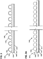
- the adhesive 1010 completely covers the cables 1002 such that each cable 1002 must break through the top surface of the adhesive 1010 in order to be separated from the support sheet 1004, as is shown for the cable 1002 at the far right of the figure.
- the support sheet first side 1006 can be provided with a tacky surface such that when the cables 1002 are laid onto the sheet 1004, for example by a dispensing head, the cables 1002 remain sufficiently affixed to the sheet 1004 until the adhesive 1010 can be applied.
- an adhesive 1010 to affix the cables 1002 to the support sheet 1004 it can be completely assured that the cables 1002 are routed such that a minimum radius is always maintained when the cables 1002 must be routed along a curved pathway.
- the disclosed system ensures that the cables 1002 are routed and secured in a proper manner to protect the cables 1002 from damage.
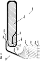
- Figures 1 and 1A show example routing paths that could be utilized to maximize the stored length of cable while ensuring minimum bend radii are maintained.
- Figure 3A shows an alternate arrangement in which the adhesive 1010 is applied between the cables 1002 and the support sheet 1004.
- the adhesive 1010 may be applied directly to the support sheet 1004 along a desired routing path for each individual cable 1002.
- the adhesive 1006 may be applied across some or all of the first side 1006 of the support sheet 1004 without defining a desired cable routing pathway.
- the adhesive 1010 is applied to the first surface 1006, the cables 1002 are subsequently arranged on the support sheet first side 1006, and the adhesive 1010 cures such that the exposed portions of the adhesive 1010 not covered by cables 1002 no longer have an adhesive quality.
- the adhesive is applied to the cables 1002 which are then arranged onto the support sheet first side 1006.
- the adhesive 1010 can also be utilized to glue the cables 1002 to each other to form a ribbon from which the cables 1002 can be individually peeled either before or after the cables 1002 have been peeled from the support sheet first side 1006.
- the second side 1008 of the support sheet 1004 may also be provided with an adhesive 1012.
- the adhesive 1012 may be any type of adhesive, for example a silicon-based adhesive.
- the adhesive 1012 may be provided over a portion or the entirety of the second side 1008 of the support sheet 1004. Where not provided over the entire surface, the adhesive 1012 may be provided in a random manner or in a pattern, such as a cross hatching-type pattern or a zig-zag pattern.
- a protective sheet 1014 may be provided to cover the adhesive 1012. To expose the adhesive 1012, the protective sheet 1014 can be peeled away from the adhesive 1012 and discarded.
- the protective sheet 1014 can be made from any of a variety of materials known in the art for protecting adhesives, for example coated paper-based materials.
- the support sheet 1004 can also be provided without an adhesive 1012 and may instead be configured to be mechanically attached to another surface.
- the support sheet 1004 can be held by clips or can engage with slots provided on a structure, for example a tray.
- the support sheet 1004 may also be provided with apertures through which clips or other mechanical fasteners can extend.
- the support sheet 1004 can also be configured such that it is a stand-alone storage structure without features allowing the sheet to be secured to another structure.
- the support sheet 1004 can be provided with a specified shape and size to define a desired routing path for the cables 1002.
- the support sheet 1004 is shaped for installation within a fiber optic support tray 22, wherein the cables 1002 are arranged to extend between a splice tray 112 and the fiber optic adapters 108 of the support tray 22.
- the support tray 22 and related features are discussed in further detail below.
- an application involving a support tray 22 and splice tray 112 is described herein, the implementation of the cable management arrangement 1000 is in no way limited to such an application. Rather, the cable management arrangement 1000 can be used in any application where it is desired to have a pre-determined length of cable removably adhered to a support sheet that itself can be adhered to a support surface.
- the support sheet 1004 can be characterized as including a first portion 1004a, a second portion 1004b, and a third portion 1004c that are disposed at non-zero angles to each other, thus requiring the cables to be bent or curved as they transition from one portion to another.
- the first portion 1004a is shaped to match the general shape of the splice tray 112, and is provided with adhesive 1012 on the second side 1008 to allow the first portion 1004a to be adhered to the bottom side of the splice tray 112.
- the protective sheet 1014 is also shaped to match the first portion 1004a.
- the adhesive 1012 and protective sheet 1014 can be seen as being generally present at a peel off area 1005 where the cables 1002 can be peeled away from the support sheet 1004.
- the cables 1002 can be attached to the support sheet 1004 as previously described and as shown at Figures 3 and 3A .
- a second sheet 1016 may be added to cover the cables 1002, as shown at Figures 3B .
- an adhesive 1010 can be utilized to secure the sheets 1004 and 1016 together against the cables 1002.
- the adhesive 1012 and protection sheet 1014 can be provided, if desired.
- the adhesive and protection sheet can be excluded from the construction as is the case at least for the second portion 1004b.
- the first portion 1004a can also be provided with an aperture 1004d at which the second end 1002f of the cables 1002 reside which allows the second ends 1002f to be free from adhesive.
- This configuration provides a manual location for starting the removal of the cable 1002 from the support sheet 1004 and also ensures that the adhesive 1012 does not interfere or otherwise damage the ends 1002f.
- the second end 1002f is fanned out such that the cables 1002 have a slightly wider spacing between them. This construction allows for the selected cables 1002 to be individually peeled from the support sheet, if desired.
- the cables 1002 disposed on the first portion 1004a of the support sheet 1004 are arranged adjacent to each other and are provided in a looped or coiled fashion such that a desired length of the cables 1002 can be stored on the first portion 1004a. As shown, the cables 1002 are looped or coiled twice proximate the perimeter edge of the first portion 1004a.
- the cables 1002 can be peeled from the first portion 1004a by their second ends 1004b, which allows the cables 1002 to be routed over to the splice holders 50 on the top side of the splice tray 112 (see Figure 15 ). The remaining loose portion of the cables 1002 can be held at storage locations 52 on the splice tray 112.
- the stored length of each cable 1002 on the first portion 1004a is about 2 meters, wherein any length up to that amount can be peeled away from the sheet 1004. In many applications, at least one meter will be removed from the sheet 1004 to allow for enough length to perform a splicing or other action. As stated previously, the cables 1002 can be adhered to each other 1002 such that all of the cables can be removed from the support sheet 1004 individually or together as a ribbon and subsequently peeled from the ribbon if removed together.
- the second portion 1004b of the support sheet 1004 provides for a routing pathway for the cables 1002 which brings the cables 1002 from the splice tray 112 towards the adapters 108 to which the cables 1002 will connect. Accordingly, the cables 1002 are disposed in relatively close proximity to each other on the second portion 1004b and the second portion 1004b is relatively narrow.
- the third portion 1004c provides a fan out region such that the cables 1002 can be separated from each other sufficiently to allow for the connectors 110 to be installed and to allow for alignment between the connectors 110 and the adapters 108 to which they are configured to connect.
- the support sheet 1004 is shown as having specifically shaped first, second, and third portions 1004a, 1004b, 1004c, the support sheet 1004 can be given any shape to suit a particular application.
- Figures 6-11 show three additional arrangements of the cable management arrangement 1000 in which the second portion 1004b of the support sheet 1004 is provided at different lengths to route the cables 1002 to different locations within the support tray 22.
- the arrangement of Figures 1 and 2 can be referred to as cable management arrangement 1000a
- the arrangement of Figures 6 and 7 can be referred to as cable management arrangement 1000b
- the arrangement of Figures 8 and 9 can be referred to as cable management arrangement 1000c
- the arrangement of Figures 10 and 11 can be referred to as cable management arrangement 1000d.
- many other arrangements are possible.
- a telecommunications panel 100 (e.g., an enclosure, an optical distribution frame, etc.) is illustrated according to the principles of the present disclosure, within which the disclosed cable management arrangement 1000 may be utilized.
- the telecommunications panel 100 may be included in a cabinet 200 of a telecommunications system 1.
- the telecommunications panel 100 and/or the cabinet 200 may be used for various purposes in telecommunications systems and may include a chassis 10 to which a plurality of stacked multi-positionable tray assemblies 20 may be removably attached.
- the multi-positionable tray assembly 20 includes a support tray 22 (e.g., a sub-rack) and a support arm 24 that are pivotally connected to each other via a pivot joint 26 that allows the tray assembly 20 to be moved between a folded position and an access position.
- a support tray 22 e.g., a sub-rack
- a support arm 24 that are pivotally connected to each other via a pivot joint 26 that allows the tray assembly 20 to be moved between a folded position and an access position.
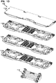
- the support tray 22 houses a cable management structure 102 including, for example, stacked splice trays 112 and a patch panel 104.
- a snap-fit cable management structure 102 is shown which includes a plurality of splice trays 112 (112a, 112b, 112c, 112d) that are snap-fit and pivotally mounted to a base structure 113 which is in turn snap-fit into a tray 22.
- trays 112 may be splitter trays.
- patch cords 1002 may enter the telecommunications panel 100 and/or the cabinet 200 and be interconnected at the patch panel 104.
- the patch panel 104 may include a plurality of fiber optic adapters 108. Fiber optic connectors 110, 114 that terminate ends of the patch cords 1002, 304 may connect with the fiber optic adapters 108 of the patch panel 104.
- the interconnections at the patch panel 104 may be rearranged from time-to-time, as desired, for changing configurations of the telecommunications system.
- the telecommunications panel 100 may further hold splitters, filters, and various other telecommunications components.
- an example telecommunications tray assembly 20 which utilizes each of the cable management arrangements 1000a, 1000b, 1000c, 1000d for a corresponding splice tray 112a, 112b, 112c, 112d in a tray 22 of a tray assembly 20.
- the cable management arrangement 1000a is shown with cables 1002 extending beyond the support sheet 1004 with attached connectors 110.
- each of the cable management arrangements 1000a ⁇ 1000d could be connectorized, although it is entirely possible to provide the arrangements without connectors, as shown.
- the support sheet first portion 1004a of the cable management arrangement 1000a is adhered to the bottom surface of the splice tray 112a via the adhesive 1012.
- attachment may be via a fastener system (e.g. clamping, bolting, clips, screws, slots that receive the support sheet edges, etc.).
- the cable management arrangements 1000b, 1000c, and 1000d are similarly attached to the respective splice trays 112b, 112c, and 112d.
- This arrangement in which each individual cable 1002 is adjacent to other cables 1002 (i.e. not bundled over other cables) provides for a very flat configuration which can easily fit between the trays 112a - 112d without causing additional bulk or requiring additional clearances.
- Each of the support sheet second portions 1004b extends into and along a side channel 23 defined within the tray 22 in a direction towards the adapters 108.
- the second portions 1004b at this location serve as a bending or hinge point for the cables 1002 when the respective tray 112 is opened and closed.
- the support sheet 1004 is provided with enough flexibility to enable this function, but with enough stiffness to prevent undue bending or kinking of the cables 10002.
- the support sheet second portions 1004b further extend laterally over from the side channel 23 into a front area 25 defined between the trays 112 and adapters 108. As can be readily seen at Figures 16-18 , the cable support sheet second portions 1004b are disposed over each other in a flat arrangement.
- the support sheet second and third portions 1004b, 1004c are together arranged to allow the connectors 110 associated with the cable management arrangement 1000 to be aligned with the adapters 108 to which they can be attached. This configuration ensures that sufficient alignment is achieved such that the cables 1002 do not have to bend sharply to accommodate the connectors 110 attaching to the adapters 108. Additionally, and as mentioned previously, the routing of the cables 1002 on the support sheet 1004 is controlled to prevent the cables 1002 from being exposed to sharp bends or kinking that may damage the cables 1002.
- the third portion 1004c in particular minimizes required bending of the cables 1002 by spreading out the cables 1002 such that each individual cable 1002 aligns with an individual adapter 108, to the extent possible.
- the disclosed approach of utilizing the cable management arrangements 1000a - 1000d allows for the cables 1002 from one tray 112a - 112d to be routed to the adapters 108 without the potential entanglement from cables 1002 associated with the other trays. Additionally, the disclosed arrangement results in a flattened cable arrangement and therefore requires less space within the tray 22 for cable routing. Yet another advantage of this arrangement is that the cables 1002 associated with a particular tray 112a - 122d can be easily removed from the tray 22 without interference from the cables 1002 associated with the other trays 112a - 112d. These are significant improvements over prior art arrangements in which individual cables extend from the trays 112a - 112d to the adapters 108 in a general bundle where the likelihood of entanglement is increased and separation and identification of particular cables can be time consuming and cumbersome.
- a user 1050 can selectively remove an individual cable 1002 from the stored cables 1002 below the tray 112 and peel as much of the cable from the tray 112 as desired.
- This partially removed cable 1002 can then be routed to the top side of the tray 112 where it can be spliced with another cable or telecommunications component and mounted to the tray 112.
- This feature not only allows for the previously mentioned storage benefits, but also allows for cables 1002 to reside beneath the trays 112 until they are actually needed so that additional connections can be made when needed without requiring the installation of additional cable.
- a tray 112, or other telecommunications component can be provided with a factory mounted cable management arrangement 1000.
- the cables 1002 of such a configuration could also be connectorized with connectors 110, which would allow an installer to simply identify a tray and cable management arrangement 1000 combination that suits a particular purpose and then install the combination as a single unit. This approach can result in significant installation cost savings whether it occurs within the factory or in the field.
Abstract
Description
- This application claims the benefit of
U.S. Patent Application Serial No. 62/277,774, filed on January 12, 2016 U.S. Patent Application Serial No. 62/286,101, filed on January 22, 2016 - The present invention relates to arrangements adapted to manage and control telecommunications and other types of cables in an effective manner.
- Numerous telecommunications panels exist today and are used in various equipment applications. Conventional telecommunications panels generally include telecommunications cables that are independent routed between telecommunications components. The identification and separation of individual or specific cables can be problematic for these types of installations.
- Cable management arrangements are disclosed in which one or more cables are removably secured to a carrier or support sheet structure. The cables can be arranged in any desired manner and length on the carrier or support sheet structure. In one aspect, the cables are arranged in a coiled or serpentine manner, and can be peeled away from the carrier or support sheet structure. In this manner, an arrangement can be factory produced in which the cables are securely stored on the carrier or sheet and can then be later selectively peeled from the carrier or sheet in the field during installation. Such an approach also ensures that the cables are arranged so that minimum bend radius limitations are maintained. As a result, quality control can be maintained at a high level during factory production. The resulting construction is also easily transportable while maintaining the desired routing and storage patterns.
- The carrier or support sheet can be provided with a specifically designed shape to allow for cable routing within an environment, for example within a fiber optic storage tray. In this manner, entire lengths of individual cables do not need to be routed and managed in the field. Rather, an installer can simply place the carrier or support sheet at the desired location, and subsequently remove the necessary length of cable to provide the final connection between the cables and other devices or cables. In some examples, portions of the cables are permanently secured to the carrier or sheet while other portions of the cables can be peeled from the carrier or sheet. For example, the cables may be permanently attached to a zone or portion of the carrier or sheet responsible for routing the cables from one location to another while the cables may be removable from a portion or zone of the carrier or sheet responsible for storing lengths of cable that are intended to be removed such that they can be routed to a different location. As will be further appreciated in the remaining portions of this application, the disclosed arrangements and methods represent a significant advance over approaches requiring individual installation and routing of cables.
- The disclosure includes multiple embodiments of cable management arrangements. In one example, at least one cable, or a plurality of cables extending between first and second ends is, provided. The arrangement can also include a supporting sheet having a first side and a second side, wherein the one cable or the plurality of cables is removably adhered to the supporting sheet first side by a first adhesive. A second adhesive can be provided on at least a portion of the supporting sheet second side and a protection sheet can be provided to cover the second adhesive. A protection sheet can be provided that is removable from the supporting sheet to allow the second adhesive to be exposed such that the supporting sheet can be adhered to a surface.
- A telecommunications arrangement is also disclosed in which the aforementioned cable management arrangement is mounted to a telecommunications tray, for example a splice tray, via the second adhesive or by a fastener system (e.g. clamping, bolting, clips, slots that receive the support sheet edges, etc.). Multiples of the telecommunications trays can be mounted within a support tray of a support tray assembly that can in turn be mounted within a telecommunications cabinet.
- A method of installing telecommunications cables in a telecommunications assembly is also disclosed. The method can include: providing a telecommunications tray having a plurality of cables adhered to a bottom side of the tray that extend to optical connectors; installing the telecommunications tray within a tray assembly having a plurality of adapters; connecting at least some of the adapters to at least some of the connectors; peeling at least a portion of some of the cables from the bottom side of the telecommunications tray and routing the portion to a top side of the telecommunications tray; and connecting the at least some cables to a telecommunications component or splicing one or more of the cables peeled from the sheet to other cables.
- An arrangement and method of installing a telecommunications cable is also disclosed. The method can include: providing a telecommunications device having a cable adhered to the device; peeling at least a portion of the cable from the telecommunications device and routing the portion to a telecommunications component or splicing the cable to another cable.
- Aspects of the disclosure are directed to a multi-positionable tray assembly for mounting within a chassis of a telecommunications panel. In one aspect, the multi-positionable tray assembly includes a tray and a support arm. The tray is configured to support at least one cable management structure while the support arm is connected to and supports the tray at a pivot joint. This structure allows the tray to be rotatable about the pivot joint at a pivot axis between a folded position and an access position. In some examples, the cables are fiber optic cables. In some examples, one end of the fiber optic cables is connectorized.
- The accompanying drawings, which are incorporated in and constitute a part of the description, illustrate several aspects of the present disclosure. A brief description of the drawings is as follows:
-
Figure 1 is a top view of an example cable management arrangement in accordance with principles of the present disclosure. -
Figure 1A is a top view of an example cable management arrangement in accordance with principles of the present disclosure. -
Figure 2 is a top view of the cable management arrangement shown inFigure 1 with a peel off area identified on the cable management arrangement. -
Figure 3 is an example schematic cross-sectional view of the cable management arrangement shown inFigures 1 or 1A at a peel off area. -
Figure 3A is an example schematic cross-sectional view of the cable management arrangement shown inFigures 1 or 1A at a peel off area. -
Figure 3B is an example schematic cross-sectional view of the cable management arrangement shown inFigures 1 or 1A outside of the peel off area. -
Figure 4 is a schematic cross-sectional view of an example cable usable with the cable management arrangement shown inFigure 1 . -
Figure 5 is a schematic cross-sectional view of an optical fiber of the cable shown inFigure 4 . -
Figure 6 is a top view of an example cable management arrangement in accordance with principles of the present disclosure. -
Figure 7 is a top view of the cable management arrangement shown inFigure 6 with a peel off area identified on the cable management arrangement. -
Figure 8 is a top view of an example cable management arrangement in accordance with principles of the present disclosure. -
Figure 9 is a top view of the cable management arrangement shown inFigure 8 with a peel off area identified on the cable management arrangement. -
Figure 10 is a top view of an example cable management arrangement in accordance with principles of the present disclosure. -
Figure 11 is a top view of the cable management arrangement shown inFigure 10 with a peel off area identified on the cable management arrangement. -
Figure 12 is a perspective view of an example telecommunications panel including a plurality of multi-positionable tray assemblies in accordance with principles of the present disclosure. -
Figure 13 is an exploded view of a cable management structure usable within the tray assembly shown inFigure 12 . -
Figure 14 is a view of the cable management structure shown inFigure 13 aligned with a tray of the multi-positionable tray assembly shown inFigure 12 . -
Figure 15 is a front perspective view of an exemplary multi-positionable tray assembly usable with the telecommunications panel shown inFigure 12 and including multiples of the cable management arrangements shown inFigures 1-2 and6-10 . -
Figure 16 is a rear perspective view of the tray assembly shown inFigure 15 with portions of the tray not shown to further illustrate the interior components of the tray assembly. -
Figure 17 is a side perspective view of the tray assembly shown inFigure 15 with portions of the tray not shown to further illustrate the interior components of the tray assembly. -
Figure 18 is a front left perspective view of the tray assembly shown inFigure 15 with a splice tray of the tray assembly shown in a raised position. -
Figure 19 is a front right perspective view of the tray assembly shown inFigure 15 with a splice tray of the tray assembly shown in a raised position. -
Figure 20 is a front right perspective view of the tray assembly shown inFigure 15 with a splice tray of the tray assembly shown in a raised position and showing an operator removing a single cable from the cable management arrangement. - Reference will now be made in detail to exemplary aspects of the present disclosure that are illustrated in the accompanying drawings. Whenever possible, the same reference numbers will be used throughout the drawings to refer to the same or similar parts.
- Referring to
Figures 1 to 3 , an example of acable management arrangement 1000 is presented. Thecable management arrangement 1000 is provided to efficiently manage the routing ofcables 1002. Thecable management arrangement 1000 is shown as including a plurality ofcables 1002 adhered or otherwise mounted to asupport sheet 1004. In the example shown, 12cables 1002 are provided. However, more orfewer cables 1002 may be provided, for example any number of cables between 1 and 48cables 1002. More than 48cables 1002 may also be provided. Thecables 1002 may be any type of cable, for example, power cables and/or telecommunications cables and data cables having a signal conveying member(s), such as optical fibers, copper wire, metal wire, and twisted pair cables. Different types ofcables 1002 may also be adhered to thesame support sheet 1004 as well, for example, a power cable and a telecommunications cable. One example of acable 1002 is shown atFigure 4 . As shown,cable 1002 has ajacket 1002a, astrengthening layer 1002b, anaramid cladding layer 1002c, abuffer tube 1002d, and a plurality ofoptical fibers 1003. Referring toFigure 5 , an example of anoptical fiber 1003 is shown. As shown,optical fiber 1003a has acore 1003a, acladding layer 1003b, a coating/acrylate later 1003c, and ajacket 1003d. In some examples, thecables 1002 are about 250 micrometers in diameter. Many other types of cables are usable with the concepts disclosed herein. - In the example shown, each of the
cables 1002 extends between afirst end 1002e and asecond end 1002f. The first ends 1002e are shown as being provided withconnectors 110 which can be, for example, optical type connectors, such as LC type connectors. In one example, theconnectors 110 are mounted directly to thesheet 1004. The second ends 1002f are shown as being free ends that can be connected to telecommunications components, for example the terminals of an optical splice or splitter tray and/or to connectors. - As most easily seen at
Figure 3 , thesupport sheet 1004 has afirst side 1006 and an oppositesecond side 1008. Thesupport sheet 1004 can be formed from a variety of materials, for example, polymeric or plastic materials and paper-based materials. Thesupport sheet 1004 may be made from any material capable of functioning as a carrier for thecables 1002. Additionally, thesupport sheet 1004 can be flexible, thereby allowing thesheet 1004 to conform to irregular surfaces and/or to allow the sheet, or portions of the sheet, to be easily routed within an installed environment. In one aspect, thecables 1002 are removably affixed to thefirst side 1006 of thesupport sheet 1004. In one example, thecables 1002 are affixed to thefirst side 1006 by an adhesive 1010, for example a sprayed silicone adhesive or shrink-wrapped foil. In the example shown atFigure 3 , the adhesive 1010 is sprayed or otherwise formed onto thecables 1002 and support sheetfirst side 1006 after the cables have been oriented as desired on thefirst side 1006 of thesupport sheet 1004. In the example shown atFigure 3 , the adhesive 1010 completely covers thecables 1002 such that eachcable 1002 must break through the top surface of the adhesive 1010 in order to be separated from thesupport sheet 1004, as is shown for thecable 1002 at the far right of the figure. - The support sheet
first side 1006 can be provided with a tacky surface such that when thecables 1002 are laid onto thesheet 1004, for example by a dispensing head, thecables 1002 remain sufficiently affixed to thesheet 1004 until the adhesive 1010 can be applied. By using an adhesive 1010 to affix thecables 1002 to thesupport sheet 1004, it can be completely assured that thecables 1002 are routed such that a minimum radius is always maintained when thecables 1002 must be routed along a curved pathway. Thus, the disclosed system ensures that thecables 1002 are routed and secured in a proper manner to protect thecables 1002 from damage.Figures 1 and 1A show example routing paths that could be utilized to maximize the stored length of cable while ensuring minimum bend radii are maintained. -
Figure 3A shows an alternate arrangement in which the adhesive 1010 is applied between thecables 1002 and thesupport sheet 1004. In such arrangements, the adhesive 1010 may be applied directly to thesupport sheet 1004 along a desired routing path for eachindividual cable 1002. Alternatively, or in addition, the adhesive 1006 may be applied across some or all of thefirst side 1006 of thesupport sheet 1004 without defining a desired cable routing pathway. In one example, the adhesive 1010 is applied to thefirst surface 1006, thecables 1002 are subsequently arranged on the support sheetfirst side 1006, and the adhesive 1010 cures such that the exposed portions of the adhesive 1010 not covered bycables 1002 no longer have an adhesive quality. In one example, the adhesive is applied to thecables 1002 which are then arranged onto the support sheetfirst side 1006. The adhesive 1010 can also be utilized to glue thecables 1002 to each other to form a ribbon from which thecables 1002 can be individually peeled either before or after thecables 1002 have been peeled from the support sheetfirst side 1006. - The
second side 1008 of thesupport sheet 1004 may also be provided with an adhesive 1012. The adhesive 1012 may be any type of adhesive, for example a silicon-based adhesive. The adhesive 1012 may be provided over a portion or the entirety of thesecond side 1008 of thesupport sheet 1004. Where not provided over the entire surface, the adhesive 1012 may be provided in a random manner or in a pattern, such as a cross hatching-type pattern or a zig-zag pattern. To protect the adhesive 1012 until thesheet 1004 is ready to be applied to a mounting surface, aprotective sheet 1014 may be provided to cover the adhesive 1012. To expose the adhesive 1012, theprotective sheet 1014 can be peeled away from the adhesive 1012 and discarded. Theprotective sheet 1014 can be made from any of a variety of materials known in the art for protecting adhesives, for example coated paper-based materials. Thesupport sheet 1004 can also be provided without an adhesive 1012 and may instead be configured to be mechanically attached to another surface. In some examples, thesupport sheet 1004 can be held by clips or can engage with slots provided on a structure, for example a tray. Thesupport sheet 1004 may also be provided with apertures through which clips or other mechanical fasteners can extend. Thesupport sheet 1004 can also be configured such that it is a stand-alone storage structure without features allowing the sheet to be secured to another structure. - In one example, the
support sheet 1004 can be provided with a specified shape and size to define a desired routing path for thecables 1002. In the embodiment shown, thesupport sheet 1004 is shaped for installation within a fiberoptic support tray 22, wherein thecables 1002 are arranged to extend between asplice tray 112 and thefiber optic adapters 108 of thesupport tray 22. Thesupport tray 22 and related features are discussed in further detail below. Although an application involving asupport tray 22 andsplice tray 112 is described herein, the implementation of thecable management arrangement 1000 is in no way limited to such an application. Rather, thecable management arrangement 1000 can be used in any application where it is desired to have a pre-determined length of cable removably adhered to a support sheet that itself can be adhered to a support surface. - As shown, the
support sheet 1004 can be characterized as including afirst portion 1004a, asecond portion 1004b, and athird portion 1004c that are disposed at non-zero angles to each other, thus requiring the cables to be bent or curved as they transition from one portion to another. Thefirst portion 1004a is shaped to match the general shape of thesplice tray 112, and is provided with adhesive 1012 on thesecond side 1008 to allow thefirst portion 1004a to be adhered to the bottom side of thesplice tray 112. Theprotective sheet 1014 is also shaped to match thefirst portion 1004a. - Referring to
Figures 2 ,7 ,9 , and11 , the adhesive 1012 andprotective sheet 1014 can be seen as being generally present at a peel offarea 1005 where thecables 1002 can be peeled away from thesupport sheet 1004. At this area, thecables 1002 can be attached to thesupport sheet 1004 as previously described and as shown atFigures 3 and 3A . At areas where it is not desired that thecables 1002 can be peeled away from thesupport sheet 1004, such as atportions second sheet 1016 may be added to cover thecables 1002, as shown atFigures 3B . In such an arrangement, an adhesive 1010 can be utilized to secure thesheets cables 1002. At such locations, the adhesive 1012 andprotection sheet 1014 can be provided, if desired. Alternatively, the adhesive and protection sheet can be excluded from the construction as is the case at least for thesecond portion 1004b. Once acable 1002 is peeled from thesheet 1004 and reaches the location at which thesecond sheet 1016 is disposed (e.g. at thesecond portion 1004b), thecable 1002 is prevented from being further removed by thesecond sheet 1016. Thesecond sheet 1016 also imparts additional stiffness to the resulting cable ribbon. The thickness and materials of thesheets - The
first portion 1004a can also be provided with anaperture 1004d at which thesecond end 1002f of thecables 1002 reside which allows the second ends 1002f to be free from adhesive. This configuration provides a manual location for starting the removal of thecable 1002 from thesupport sheet 1004 and also ensures that the adhesive 1012 does not interfere or otherwise damage theends 1002f. As can be seen, thesecond end 1002f is fanned out such that thecables 1002 have a slightly wider spacing between them. This construction allows for the selectedcables 1002 to be individually peeled from the support sheet, if desired. - The
cables 1002 disposed on thefirst portion 1004a of thesupport sheet 1004 are arranged adjacent to each other and are provided in a looped or coiled fashion such that a desired length of thecables 1002 can be stored on thefirst portion 1004a. As shown, thecables 1002 are looped or coiled twice proximate the perimeter edge of thefirst portion 1004a. Thecables 1002 can be peeled from thefirst portion 1004a by theirsecond ends 1004b, which allows thecables 1002 to be routed over to thesplice holders 50 on the top side of the splice tray 112 (seeFigure 15 ). The remaining loose portion of thecables 1002 can be held atstorage locations 52 on thesplice tray 112. In one example, the stored length of eachcable 1002 on thefirst portion 1004a is about 2 meters, wherein any length up to that amount can be peeled away from thesheet 1004. In many applications, at least one meter will be removed from thesheet 1004 to allow for enough length to perform a splicing or other action. As stated previously, thecables 1002 can be adhered to each other 1002 such that all of the cables can be removed from thesupport sheet 1004 individually or together as a ribbon and subsequently peeled from the ribbon if removed together. - The
second portion 1004b of thesupport sheet 1004 provides for a routing pathway for thecables 1002 which brings thecables 1002 from thesplice tray 112 towards theadapters 108 to which thecables 1002 will connect. Accordingly, thecables 1002 are disposed in relatively close proximity to each other on thesecond portion 1004b and thesecond portion 1004b is relatively narrow. Thethird portion 1004c provides a fan out region such that thecables 1002 can be separated from each other sufficiently to allow for theconnectors 110 to be installed and to allow for alignment between theconnectors 110 and theadapters 108 to which they are configured to connect. Although thesupport sheet 1004 is shown as having specifically shaped first, second, andthird portions support sheet 1004 can be given any shape to suit a particular application. -
Figures 6-11 show three additional arrangements of thecable management arrangement 1000 in which thesecond portion 1004b of thesupport sheet 1004 is provided at different lengths to route thecables 1002 to different locations within thesupport tray 22. For ease of reference, the arrangement ofFigures 1 and2 can be referred to ascable management arrangement 1000a, the arrangement ofFigures 6 and 7 can be referred to ascable management arrangement 1000b, the arrangement ofFigures 8 and 9 can be referred to ascable management arrangement 1000c, and the arrangement ofFigures 10 and 11 can be referred to ascable management arrangement 1000d. As stated previously, many other arrangements are possible. - Referring to
Figure 12 , a telecommunications panel 100 (e.g., an enclosure, an optical distribution frame, etc.) is illustrated according to the principles of the present disclosure, within which the disclosedcable management arrangement 1000 may be utilized. As further illustrated atFigure 1 , thetelecommunications panel 100 may be included in acabinet 200 of a telecommunications system 1. Thetelecommunications panel 100 and/or thecabinet 200 may be used for various purposes in telecommunications systems and may include achassis 10 to which a plurality of stackedmulti-positionable tray assemblies 20 may be removably attached. In one aspect, themulti-positionable tray assembly 20 includes a support tray 22 (e.g., a sub-rack) and asupport arm 24 that are pivotally connected to each other via a pivot joint 26 that allows thetray assembly 20 to be moved between a folded position and an access position. - In the example shown, the
support tray 22 houses acable management structure 102 including, for example,stacked splice trays 112 and apatch panel 104. Referring toFigures 13 and14 , one example of a snap-fitcable management structure 102 is shown which includes a plurality of splice trays 112 (112a, 112b, 112c, 112d) that are snap-fit and pivotally mounted to abase structure 113 which is in turn snap-fit into atray 22. Other arrangements are possible, for example,trays 112 may be splitter trays. - In one aspect, patch cords 1002 (shown schematically) of the
cable management arrangement 1000 and patch cords 304 (i.e., patch cables, connectorized fiber optic cables, etc.) may enter thetelecommunications panel 100 and/or thecabinet 200 and be interconnected at thepatch panel 104. Thepatch panel 104 may include a plurality offiber optic adapters 108.Fiber optic connectors 110, 114 that terminate ends of thepatch cords fiber optic adapters 108 of thepatch panel 104. The interconnections at thepatch panel 104 may be rearranged from time-to-time, as desired, for changing configurations of the telecommunications system. Thetelecommunications panel 100 may further hold splitters, filters, and various other telecommunications components. An exemplary telecommunications system 1 is shown and described inUnited States Provisional Patent Application 62/051,093, filed on September 16, 2014 PCT/EP2015/071196, filed on September 16, 2015 - Referring to
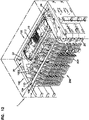
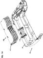
Figures 15-20 , an exampletelecommunications tray assembly 20 is presented which utilizes each of thecable management arrangements corresponding splice tray tray 22 of atray assembly 20. For the purpose of clarity, only thecable management arrangement 1000a is shown withcables 1002 extending beyond thesupport sheet 1004 with attachedconnectors 110. In an actual installation, each of thecable management arrangements 1000a ― 1000d could be connectorized, although it is entirely possible to provide the arrangements without connectors, as shown. - As most easily seen at
Figures 18 and19 , it can be seen that the support sheetfirst portion 1004a of thecable management arrangement 1000a is adhered to the bottom surface of thesplice tray 112a via the adhesive 1012. Although an adhesive connection is shown, attachment may be via a fastener system (e.g. clamping, bolting, clips, screws, slots that receive the support sheet edges, etc.). Thecable management arrangements respective splice trays individual cable 1002 is adjacent to other cables 1002 (i.e. not bundled over other cables) provides for a very flat configuration which can easily fit between thetrays 112a - 112d without causing additional bulk or requiring additional clearances. - Each of the support sheet
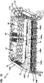
second portions 1004b extends into and along aside channel 23 defined within thetray 22 in a direction towards theadapters 108. Thesecond portions 1004b at this location serve as a bending or hinge point for thecables 1002 when therespective tray 112 is opened and closed. Thesupport sheet 1004 is provided with enough flexibility to enable this function, but with enough stiffness to prevent undue bending or kinking of the cables 10002. The support sheetsecond portions 1004b further extend laterally over from theside channel 23 into a front area 25 defined between thetrays 112 andadapters 108. As can be readily seen atFigures 16-18 , the cable support sheetsecond portions 1004b are disposed over each other in a flat arrangement. - The support sheet second and
third portions connectors 110 associated with thecable management arrangement 1000 to be aligned with theadapters 108 to which they can be attached. This configuration ensures that sufficient alignment is achieved such that thecables 1002 do not have to bend sharply to accommodate theconnectors 110 attaching to theadapters 108. Additionally, and as mentioned previously, the routing of thecables 1002 on thesupport sheet 1004 is controlled to prevent thecables 1002 from being exposed to sharp bends or kinking that may damage thecables 1002. Thethird portion 1004c in particular minimizes required bending of thecables 1002 by spreading out thecables 1002 such that eachindividual cable 1002 aligns with anindividual adapter 108, to the extent possible. - The disclosed approach of utilizing the
cable management arrangements 1000a - 1000d allows for thecables 1002 from onetray 112a - 112d to be routed to theadapters 108 without the potential entanglement fromcables 1002 associated with the other trays. Additionally, the disclosed arrangement results in a flattened cable arrangement and therefore requires less space within thetray 22 for cable routing. Yet another advantage of this arrangement is that thecables 1002 associated with aparticular tray 112a - 122d can be easily removed from thetray 22 without interference from thecables 1002 associated with theother trays 112a - 112d. These are significant improvements over prior art arrangements in which individual cables extend from thetrays 112a - 112d to theadapters 108 in a general bundle where the likelihood of entanglement is increased and separation and identification of particular cables can be time consuming and cumbersome. - Still referring to
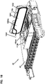
Figures 19 and20 , it can be seen that auser 1050 can selectively remove anindividual cable 1002 from the storedcables 1002 below thetray 112 and peel as much of the cable from thetray 112 as desired. This partially removedcable 1002 can then be routed to the top side of thetray 112 where it can be spliced with another cable or telecommunications component and mounted to thetray 112. This feature not only allows for the previously mentioned storage benefits, but also allows forcables 1002 to reside beneath thetrays 112 until they are actually needed so that additional connections can be made when needed without requiring the installation of additional cable. In one example, atray 112, or other telecommunications component, can be provided with a factory mountedcable management arrangement 1000. Thecables 1002 of such a configuration could also be connectorized withconnectors 110, which would allow an installer to simply identify a tray andcable management arrangement 1000 combination that suits a particular purpose and then install the combination as a single unit. This approach can result in significant installation cost savings whether it occurs within the factory or in the field. - While this invention has been particularly shown and described with references to preferred embodiments thereof, it will be understood by those skilled in the art that various changes in form and details may be made therein without departing from the scope of the invention encompassed by the appended claims. The drawings are not necessarily to scale, emphasis instead being placed upon illustrating the principles of the invention and other modifications within the scope. Any such modifications or variations that fall within the purview of this description are intended to be included therein as well. It is understood that the description herein is intended to be illustrative only and is not intended to be limitative.
-
- 1
- telecommunications system
- 10
- chassis
- 20
- multi-positionable tray assembly
- 22
- support tray
- 50
- holding area
- 52
- storage area
- 100
- telecommunications panel
- 102
- cable management structure
- 104
- patch panel
- 108
- fiber optic adapters
- 110
- first fiber optic connectors
- 112
- splice tray
- 112a
- splice tray
- 112b
- splice tray
- 112c
- splice tray
- 112d
- splice tray
- 200
- cabinet
- 304
- patch cord
- 1000
- cable management arrangement
- 1000a
- cable management arrangement
- 1000b
- cable management arrangement
- 1000c
- cable management arrangement
- 1000d
- cable management arrangement
- 1002
- cables
- 1002a
- jacket
- 1002b
- a strengthening layer
- 1002c
- an aramid cladding layer
- 1002d
- a buffer tube
- 1002e
- first end
- 1002f
- second end
- 1003
- optical fiber
- 1003a
- core
- 1003b
- cladding layer
- 1003c
- coating/acrylate later
- 1003d
- jacket
- 1004
- support sheet
- 1004a
- first portion
- 1004b
- second portion
- 1004c
- third portion
- 1006
- first side
- 1008
- second side
- 1010
- first adhesive
- 1012
- second adhesive
- 1014
- protective sheet
- 1016
- second sheet
- This application is a divisional application of European patent application number
EP 17701801.7 EP 3 403 124 The original claims of the parent application are repeated below as clauses in the present specification and form part of the content of this divisional application as filed. -
- 1. A cable management arrangement (1000) comprising:
- (a) a plurality of cables (1002) extending between first and second ends;
- (b) a supporting sheet (1004) having a first side and a second side, at least a portion of the plurality of cables being removably adhered to the supporting sheet first side by a first adhesive (1010);
- (c) a second adhesive (1012) provided on at least a portion of the supporting sheet second side; and
- (d) a protection sheet (1014) covering the second adhesive, the protection sheet being removable from the supporting sheet to allow the supporting sheet to be adhered to a surface.
- 2. The cable management arrangement (1000) of clause 1, wherein the plurality of cables are fiber optic cables.
- 3. The cable management arrangement (1000) of clause 2, further comprising a plurality of optical connectors (110) provided on the first ends of the plurality of cables.
- 4. The cable management arrangement (1000) of clause 1, wherein the first adhesive is a silicone-based adhesive.
- 5. The cable management arrangement (1000) of clause 1, wherein the plurality of cables includes at least one power cable and at least one telecommunications cable.
- 6. The cable management arrangement (1000) of clause 5, wherein the plurality of cables are non-overlapping and are arranged in a side-by-side arrangement.
- 7. The cable management arrangement (1000) of clause 6, wherein the plurality of cables are adhesively bonded to each other.
- 8. A cable management arrangement (1000) comprising:
- (a) a plurality of optical fibers (1002) extending between first and second ends, the first ends being provided with optical connectors (110);
- (b) a supporting sheet (1004) having a first side and a second side, at least a portion of the plurality of optical fibers being removably adhered to the supporting sheet on the first side;
- (c) an adhesive (1012) provided on at least a portion of the supporting sheet second side; and
- (d) a protection sheet (1014) covering the adhesive, the protection sheet being removable from the supporting sheet to allow the supporting sheet to be adhered to a surface.
- 9. The cable management arrangement (1000) of clause 8, wherein the first adhesive is a silicone based adhesive.
- 10. The cable management arrangement (1000) of clause 8, wherein the cables are non-overlapping and are arranged in a side-by-side arrangement.
- 11. The cable management arrangement (1000) of
clause 10, wherein the plurality of cables are adhesively bonded to each other. - 12. The cable management arrangement (1000) of clause 8, wherein the optical connectors are LC type connectors.
- 13. The cable management arrangement (1000) of clause 8, wherein the supporting sheet has a first portion (1004a) and a second portion (1004b) disposed at a non-zero angle to the first portion.
- 14. The cable management arrangement (1000) of clause 13, wherein the adhesive is provided only at the first portion.
- 15. A telecommunications assembly (20) comprising:
- (a) a telecommunications tray (112) having a first side and a second side;
- (b) a cable management arrangement (1000) including:
- (i) a plurality of optical fibers (1002) extending between first and second ends, the first ends being provided with optical connectors (110);
- (ii) a supporting sheet (1004) having a first side and a second side, at least a portion of the plurality of optical fibers being removably adhered to the supporting sheet on the first side;
- (iii) an adhesive (1012) provided on at least a portion of the supporting sheet second side, wherein the adhesive secures the supporting sheet to the telecommunications tray second side.
- 16. The telecommunications arrangement (1000) of clause 15, wherein the telecommunications tray is a splice tray.
- 17. The telecommunications arrangement (1000) of clause 15, wherein the optical connectors are LC type connectors.
- 18. The cable management arrangement (1000) of clause 8, wherein the supporting sheet has a first portion (1004a) and a second portion (1004b) disposed at a non-zero angle to the first portion.
- 19. The cable management arrangement (1000) of clause 13, wherein the first portion is secured to the telecommunications tray and the second portion extends from the telecommunications tray.
- 20. The cable management arrangement (1000) of clause 19, wherein the support sheet further includes a third portion (1004c) disposed at a non-zero angle to the second portion.
- 21. A telecommunications tray assembly (20) for mounting within a telecommunications cabinet (200), the telecommunications assembly (20) comprising:
- (a) a support tray (22) defining an interior space;
- (b) a cable management structure (102) mounted within the support tray interior space, the cable management structure (102) including at least one telecommunications component (112) having a first side and a second side;
- (c) at least one cable management arrangement (1000) including:
- (i) a plurality of optical fibers (1002) extending between first and second ends, the first ends being provided with optical connectors (110);
- (ii) a supporting sheet (1004) having a first side and a second side, at least a portion of the plurality of optical fibers being removably adhered to the supporting sheet on the first side;
- (iii) an adhesive (1012) provided on at least a portion of the supporting sheet second side, wherein the adhesive secures the supporting sheet to the at least one telecommunications component second side.
- 22. The telecommunications tray assembly (20) of clause 21, wherein the at least one telecommunications component (112) is a splice tray.
- 23. The telecommunications tray assembly (20) of clause 21, wherein the at least one telecommunications component (112) includes a plurality of telecommunications components (112) and the at least one cable management arrangement (1000) includes a plurality of cable management arrangements (1000).
- 24. A method of installing telecommunications cable in a telecommunications assembly, the method comprising:
- (a) providing a telecommunications tray having a plurality of cables adhered to a bottom side of the tray that extend to optical connectors;
- (b) installing the telecommunications tray within a tray assembly having a plurality of adapters;
- (c) connecting at least some of the adapters to at least some of the connectors;
- (d) peeling at least a portion of some of the cables from the bottom side of the telecommunications tray and routing the portion to a top side of the telecommunications tray; and
- (e) connecting the at least some cables to a telecommunications component or splicing the at least some cables to other cables.
- 25. A cable management arrangement comprising:
- (a) a cable extending between first and second ends; and
- (b) a flexible supporting sheet construction having a first side and a second side, the cable being removably adhered to only a portion of the flexible supporting sheet construction.
- 26. The cable management arrangement of clause 25, wherein the cable is in the shape of a coil when the cable is stored on the flexible supporting sheet construction.
- 27. A method of installing telecommunications cable in a telecommunications assembly, the method comprising:
- (a) providing a telecommunications tray having one or more cables adhered to a flexible supporting sheet construction;
- (b) peeling only a portion of a total adhered length of the one or more cables from the flexible supporting sheet construction; and
- (c) connecting at least one of the one or more cables to a telecommunications component or to second cable via splicing.
- 28. The method of clause 27, wherein the one or more cables is in the shape of a coil when the one or more cables is stored on the flexible supporting sheet construction.
Claims (15)
- A cable management arrangement (1000) comprising:(a) a plurality of cables (1002) extending between first and second ends;(b) a supporting sheet (1004) having a first side, at least a first portion of the plurality of cables being removably adhered to the supporting sheet first side by a first adhesive (1010), at least a second portion of the plurality of cables being permanently secured to the supporting sheet first side.
- The cable management arrangement (1000) of claim 1, further comprising:(a) a second adhesive (1012) provided on at least a portion of the supporting sheet second side; and(b) a protection sheet (1014) covering the second adhesive, the protection sheet being removable from the supporting sheet to allow the supporting sheet to be adhered to a surface.
- The cable management arrangement (1000) of claim 1, wherein the plurality of cables are fiber optic cables.
- The cable management arrangement (1000) of claim 3, further comprising a plurality of optical connectors (110) provided on the first ends of the plurality of cables.
- The cable management arrangement (1000) of claim 1, wherein the first adhesive is a silicone-based adhesive.
- The cable management arrangement (1000) of claim 1, wherein the plurality of cables includes at least one power cable and at least one telecommunications cable.
- The cable management arrangement (1000) of claim 5, wherein the plurality of cables are non-overlapping and are arranged in a side-by-side arrangement.
- The cable management arrangement (1000) of claim 6, wherein the plurality of cables are adhesively bonded to each other.
- The cable management arrangement (1000) of claim 1, further including a second sheet (1016) covering the second portion of the plurality of cables.
- The cable management arrangement (1000) of claim 9, wherein the first adhesive secures the supporting sheet and second sheet together against the plurality of cables.
- A telecommunications assembly (20) comprising:(a) a telecommunications tray (112) having a first side and a second side; and(b) the cable management arrangement (1000) of any preceding claim,
wherein a second side of the supporting sheet is adhered to the telecommunications tray second side. - The telecommunications assembly (20) of claim 11, wherein the telecommunications tray is a splice tray.
- A telecommunications assembly (20) for mounting within a telecommunications cabinet (200), the telecommunications assembly (20) comprising:(a) a support tray (22) defining an interior space;(b) a cable management structure (102) mounted within the support tray interior space, the cable management structure including at least one telecommunications component (112) having a first side and a second side; and(c) the cable management arrangement (1000) of any preceding claim, wherein the second adhesive (1012) provided on at least a portion of the supporting sheet second side secures the supporting sheet to the at least one telecommunications component second side.
- The telecommunications assembly (20) of claim 13, wherein the at least one telecommunications component (112) is a splice tray.
- The telecommunications assembly (20) of claim 13, wherein the at least one telecommunications component (112) includes a plurality of telecommunications components (112) and the at least one cable management arrangement (1000) includes a plurality of cable management arrangements (1000).
Applications Claiming Priority (4)
| Application Number | Priority Date | Filing Date | Title |
|---|---|---|---|
| US201662277774P | 2016-01-12 | 2016-01-12 | |
| US201662286101P | 2016-01-22 | 2016-01-22 | |
| PCT/EP2017/050530 WO2017121778A1 (en) | 2016-01-12 | 2017-01-12 | Cable management arrangement |
| EP17701801.7A EP3403124B1 (en) | 2016-01-12 | 2017-01-12 | Cable management arrangement |
Related Parent Applications (2)
| Application Number | Title | Priority Date | Filing Date |
|---|---|---|---|
| EP17701801.7A Division-Into EP3403124B1 (en) | 2016-01-12 | 2017-01-12 | Cable management arrangement |
| EP17701801.7A Division EP3403124B1 (en) | 2016-01-12 | 2017-01-12 | Cable management arrangement |
Publications (1)
| Publication Number | Publication Date |
|---|---|
| EP4024108A1 true EP4024108A1 (en) | 2022-07-06 |
Family
ID=57909580
Family Applications (2)
| Application Number | Title | Priority Date | Filing Date |
|---|---|---|---|
| EP21206209.5A Pending EP4024108A1 (en) | 2016-01-12 | 2017-01-12 | Cable management arrangement |
| EP17701801.7A Active EP3403124B1 (en) | 2016-01-12 | 2017-01-12 | Cable management arrangement |
Family Applications After (1)
| Application Number | Title | Priority Date | Filing Date |
|---|---|---|---|
| EP17701801.7A Active EP3403124B1 (en) | 2016-01-12 | 2017-01-12 | Cable management arrangement |
Country Status (4)
| Country | Link |
|---|---|
| US (3) | US10732356B2 (en) |
| EP (2) | EP4024108A1 (en) |
| CN (1) | CN108603990B (en) |
| WO (1) | WO2017121778A1 (en) |
Families Citing this family (10)
| Publication number | Priority date | Publication date | Assignee | Title |
|---|---|---|---|---|
| US9417418B2 (en) | 2011-09-12 | 2016-08-16 | Commscope Technologies Llc | Flexible lensed optical interconnect device for signal distribution |
| IN2015DN02869A (en) | 2012-09-28 | 2015-09-11 | Tyco Electronics Ltd Uk | |
| WO2014052446A1 (en) | 2012-09-28 | 2014-04-03 | Tyco Electronics Uk Ltd. | Manufacture and testing of fiber optic cassette |
| US9223094B2 (en) | 2012-10-05 | 2015-12-29 | Tyco Electronics Nederland Bv | Flexible optical circuit, cassettes, and methods |
| WO2017121778A1 (en) | 2016-01-12 | 2017-07-20 | CommScope Connectivity Belgium BVBA | Cable management arrangement |
| EP3692404A4 (en) * | 2017-10-02 | 2021-06-16 | Commscope Technologies LLC | Fiber optic circuit and preparation method |
| WO2020037036A1 (en) * | 2018-08-14 | 2020-02-20 | Commscope Technologies Llc | Optical fiber cable assembly for monitoring functions |
| EP3844971A1 (en) | 2018-08-31 | 2021-07-07 | CommScope Connectivity Belgium BVBA | Telecommunications equipment cabinet |
| US11169331B2 (en) | 2019-09-05 | 2021-11-09 | TE Connectivity Services Gmbh | Flexible optical circuit with integrated fiber breakout |
| WO2021148552A1 (en) * | 2020-01-24 | 2021-07-29 | CommScope Connectivity Belgium BVBA | Telecommunications distribution elements |
Citations (2)
| Publication number | Priority date | Publication date | Assignee | Title |
|---|---|---|---|---|
| US20040161212A1 (en) * | 2003-02-18 | 2004-08-19 | Sun Maurice X. | Fiber optic apparatus |
| EP3403124A1 (en) | 2016-01-12 | 2018-11-21 | CommScope Connectivity Belgium BVBA | Cable management arrangement |
Family Cites Families (60)
| Publication number | Priority date | Publication date | Assignee | Title |
|---|---|---|---|---|
| US3777154A (en) * | 1972-02-07 | 1973-12-04 | R Lindsey | Optical data processing system |
| US4154977A (en) * | 1977-04-28 | 1979-05-15 | Akzona Incorporated | Multiconductor cable adapted for mass termination and for use in limited space |
| US4625074A (en) * | 1985-03-05 | 1986-11-25 | Cooper Industries, Inc. | Mass terminable flat cable |
| CN1008560B (en) * | 1985-07-17 | 1990-06-27 | Bicc公众有限公司 | A kind of improved fibre optic element |
| US4753509A (en) * | 1985-11-08 | 1988-06-28 | Siemens Aktiengesellschaft | Receptacle for light waveguide splice connections having adhesive glue gripping means |
| DE3640836C1 (en) * | 1986-11-29 | 1988-05-26 | Krone Ag | Splice cassette housing for optical fibers |
| US5204925A (en) * | 1991-09-11 | 1993-04-20 | At&T Bell Laboratories | Optical interconnection of circuit packs |
| US5327513A (en) * | 1992-05-28 | 1994-07-05 | Raychem Corporation | Flat cable |
| US5422439A (en) * | 1993-07-29 | 1995-06-06 | Massachusetts Manufacturing And Mining Company | Convertible cable assembly |
| US5460683A (en) * | 1994-08-19 | 1995-10-24 | Sumitomo Electric Lightwave Corp. | Method for midspan entry of optical ribbon fiber |
| DE59603441D1 (en) * | 1996-01-17 | 1999-11-25 | Siemens Ag | CABLE SLEEVE FOR LIGHT-WAVE GUIDES WITH SPLICE CASSETTES AND EXTENSION SHELVES |
| DE19625260A1 (en) * | 1996-06-25 | 1998-01-02 | Bosch Gmbh Robert | Ribbon for optical broadband in-house cabling |
| US5754724A (en) | 1996-11-08 | 1998-05-19 | Antec Corporation | Fiber optic support apparatus |
| US5902435A (en) * | 1996-12-31 | 1999-05-11 | Minnesota Mining And Manufacturing Company | Flexible optical circuit appliques |
| SE511315C2 (en) * | 1997-02-18 | 1999-09-06 | Ericsson Telefon Ab L M | Method and connecting means for a flex film and optical flex film |
| IT1291152B1 (en) * | 1997-02-27 | 1998-12-29 | Iveco Fiat | METHOD OF ASSEMBLING A PANEL, IN PARTICULAR A TRANSPARENT PANEL, ON THE EDGE OF AN OPENING IN A STRUCTURE, WITH |
| WO1999046621A1 (en) * | 1998-03-12 | 1999-09-16 | Tomoegawa Paper Co., Ltd. | Optical connection component and method of producing the same |
| SE517302C2 (en) * | 1999-05-27 | 2002-05-21 | Ericsson Telefon Ab L M | Apparatus for delimiting and separating optical fibers in an isolated space |
| JP2001051128A (en) * | 1999-08-06 | 2001-02-23 | Mitsubishi Cable Ind Ltd | Holding structure of optical fiber |
| US6445866B1 (en) * | 1999-11-29 | 2002-09-03 | Molex Incorporated | Optical interconnection apparatus and method of fabricating same |
| JP2001330738A (en) * | 2000-05-19 | 2001-11-30 | Sumitomo Electric Ind Ltd | Optical fiber sheet |
| US6352374B1 (en) * | 2000-06-08 | 2002-03-05 | Amphenol Corporation | Fiber optic connector device |
| US6442323B1 (en) * | 2001-01-05 | 2002-08-27 | Us Conec Ltd. | Flexible optical circuit having a protective foam layer |
| JP2002303737A (en) * | 2001-01-24 | 2002-10-18 | Mitsubishi Cable Ind Ltd | Optical fiber wiring board |
| US6625374B2 (en) * | 2001-03-07 | 2003-09-23 | Adc Telecommunications, Inc. | Cable storage spool |
| US6619853B2 (en) * | 2001-03-14 | 2003-09-16 | Molex Incorporated | Optical fiber interconnection system |
| JP3822448B2 (en) * | 2001-03-21 | 2006-09-20 | Nttエレクトロニクス株式会社 | Optical fiber component for connection and manufacturing method thereof |
| US7352921B2 (en) * | 2001-04-05 | 2008-04-01 | Fujikura Ltd. | Multilayer optical fiber sheet, optical fiber sheet fabricating method, and optical fiber sheet |
| US6684020B2 (en) * | 2001-06-05 | 2004-01-27 | Lucent Technologies Inc. | Optical fiber retention device |
| JP4165044B2 (en) | 2001-07-23 | 2008-10-15 | 沖電気工業株式会社 | Cell disassembly device |
| US6554483B1 (en) * | 2001-10-15 | 2003-04-29 | Molex Incorporated | Method and apparatus of cross-connecting optical fibers |
| US6614971B2 (en) * | 2001-12-04 | 2003-09-02 | Molex Incorporated | Fanout system or apparatus for a fiber optic cable and including a method of fabricating same |
| US6850671B2 (en) * | 2002-03-15 | 2005-02-01 | Sharon Carnevale | Optical circuit having legs in a stacked configuration and an associated fabrication method |
| JP3833562B2 (en) | 2002-04-18 | 2006-10-11 | 株式会社巴川製紙所 | Optical fiber surplus length processing sheet and optical fiber surplus length processing method |
| GB0211517D0 (en) * | 2002-05-20 | 2002-06-26 | Tyco Electronics Raychem Nv | Optical fibre sealing |
| US6721042B1 (en) * | 2003-02-18 | 2004-04-13 | Molex Incorporated | Fiber optic apparatus and method for cross-connecting optical fibers |
| US6885800B2 (en) * | 2003-05-29 | 2005-04-26 | Molex Incorporated | Method and apparatus of cross-connecting optical fibers with layered substrates forming fiber optic ribbons |
| US20050095406A1 (en) * | 2003-10-31 | 2005-05-05 | Gunzel Edward C. | Attachment of cables to flexible fabrics |
| WO2008010416A1 (en) * | 2006-07-19 | 2008-01-24 | Nikon Corporation | Cassette for optical fiber amplifier, optical fiber amplifier and light source device |
| US7715679B2 (en) * | 2007-05-07 | 2010-05-11 | Adc Telecommunications, Inc. | Fiber optic enclosure with external cable spool |
| US7606458B2 (en) * | 2008-02-21 | 2009-10-20 | Tyco Telecommunications (Us) Inc. | Movable optical fiber connection system and optical fiber bend limiting device for use therein |
| US7764859B2 (en) * | 2008-03-28 | 2010-07-27 | Adc Telecommunications, Inc. | Universal cable management panel |
| EP2166389A1 (en) * | 2008-09-23 | 2010-03-24 | 3M Innovative Properties Company | Enclosure for telecommunications cables, with removable organizer |
| US8346043B2 (en) * | 2009-07-30 | 2013-01-01 | Jds Uniphase Corporation | Fiber tray |
| CN102474084A (en) | 2009-08-06 | 2012-05-23 | 3M创新有限公司 | System and method for providing final drop in a living unit in a building |
| US8422846B2 (en) * | 2009-08-13 | 2013-04-16 | Commscope, Inc. Of North Carolina | Fiber management component |
| US8687934B2 (en) * | 2011-03-21 | 2014-04-01 | Tyco Electronics Corporation | Fiber optic component holders and enclosures and methods including the same |
| CN102809784B (en) * | 2011-06-02 | 2014-08-27 | 富士康(昆山)电脑接插件有限公司 | Light back plate assembly |
| US20130034324A1 (en) * | 2011-08-03 | 2013-02-07 | Baker Hughes Incorporated | Optical fiber sensor and method for adhering an optical fiber to a substrate |
| US9031360B2 (en) * | 2011-09-23 | 2015-05-12 | Tyco Electronics Nederland Bv | Flexible optical circuit |
| CN202330813U (en) * | 2011-11-30 | 2012-07-11 | 杭州兴达通信有限公司 | Optical cable terminal box |
| US9223094B2 (en) * | 2012-10-05 | 2015-12-29 | Tyco Electronics Nederland Bv | Flexible optical circuit, cassettes, and methods |
| WO2014134154A1 (en) * | 2013-02-26 | 2014-09-04 | Tyco Electronics Corporation | High density splitter aggregation module |
| JP2017515152A (en) * | 2014-04-17 | 2017-06-08 | モレックス エルエルシー | Multilayer flexible optical circuit |
| WO2016042018A2 (en) | 2014-09-16 | 2016-03-24 | Tyco Electronics Raychem Bvba | Telecommunications tray assembly |
| WO2016042034A1 (en) | 2014-09-16 | 2016-03-24 | Tyco Electronics Raychem Bvba | Multi-positionable telecommunications tray |
| CN104459920A (en) * | 2014-12-30 | 2015-03-25 | 高文亭 | Optical fiber fusion and distribution integrated unit disc |
| US9494763B2 (en) * | 2015-02-04 | 2016-11-15 | International Business Machines Corporation | Optical fiber routing mat |
| CN105086871A (en) * | 2015-09-24 | 2015-11-25 | 苏州华周胶带有限公司 | Optical fiber adhesive tape |
| US10379311B1 (en) * | 2018-04-04 | 2019-08-13 | Northrop Grumman Systems Corporation | Over-molded multi-optical fiber ribbon cable and method of making same |
-
2017
- 2017-01-12 WO PCT/EP2017/050530 patent/WO2017121778A1/en unknown
- 2017-01-12 US US16/069,831 patent/US10732356B2/en active Active
- 2017-01-12 EP EP21206209.5A patent/EP4024108A1/en active Pending
- 2017-01-12 EP EP17701801.7A patent/EP3403124B1/en active Active
- 2017-01-12 CN CN201780006452.2A patent/CN108603990B/en active Active
-
2020
- 2020-08-03 US US16/983,377 patent/US11327239B2/en active Active
-
2022
- 2022-05-06 US US17/738,957 patent/US11921327B2/en active Active
Patent Citations (2)
| Publication number | Priority date | Publication date | Assignee | Title |
|---|---|---|---|---|
| US20040161212A1 (en) * | 2003-02-18 | 2004-08-19 | Sun Maurice X. | Fiber optic apparatus |
| EP3403124A1 (en) | 2016-01-12 | 2018-11-21 | CommScope Connectivity Belgium BVBA | Cable management arrangement |
Also Published As
| Publication number | Publication date |
|---|---|
| US20190025521A1 (en) | 2019-01-24 |
| EP3403124B1 (en) | 2021-12-08 |
| CN108603990B (en) | 2021-05-28 |
| CN108603990A (en) | 2018-09-28 |
| WO2017121778A1 (en) | 2017-07-20 |
| US20200363591A1 (en) | 2020-11-19 |
| US10732356B2 (en) | 2020-08-04 |
| EP3403124A1 (en) | 2018-11-21 |
| US20220404554A1 (en) | 2022-12-22 |
| US11921327B2 (en) | 2024-03-05 |
| US11327239B2 (en) | 2022-05-10 |
Similar Documents
| Publication | Publication Date | Title |
|---|---|---|
| EP3403124B1 (en) | Cable management arrangement | |
| US6845207B2 (en) | Optical fiber enclosure system | |
| EP0623225B1 (en) | Fiber optic connection system | |
| EP2255234B1 (en) | Optical fibre organiser | |
| KR20070064604A (en) | Splice holder device | |
| EP0463749A2 (en) | Termination system of optical fibres | |
| EP2360937A1 (en) | Optical fiber cable distribution frame | |
| EP0620462A1 (en) | Splice tray rack and cabinet for fiber optic cables | |
| US20060193588A1 (en) | Fiber access terminal | |
| US20190072736A1 (en) | High density distribution frame with an integrated splicing compartment | |
| JPH05503162A (en) | Wiring board/connector holder combination device for connector holders and optical cables | |
| EP1808028A2 (en) | Fiber optic module and system including rear connectors | |
| WO2009038694A1 (en) | Multi-port optical connection terminal | |
| KR20070064605A (en) | Connector and splice holder device | |
| EP3776050A1 (en) | Flexible organizer and self-supporting unit | |
| US20160216471A1 (en) | Fiber optic assemblies with a fiber optic cable movable between cable openings | |
| US5790738A (en) | Laminated optical device assembly | |
| WO1995029418A1 (en) | Optical fibre connector | |
| US20230140141A1 (en) | Fiber optic cable management systems and methods |
Legal Events
| Date | Code | Title | Description |
|---|---|---|---|
| PUAI | Public reference made under article 153(3) epc to a published international application that has entered the european phase |
Free format text: ORIGINAL CODE: 0009012 |
|
| STAA | Information on the status of an ep patent application or granted ep patent |
Free format text: STATUS: THE APPLICATION HAS BEEN PUBLISHED |
|
| AC | Divisional application: reference to earlier application |
Ref document number: 3403124 Country of ref document: EP Kind code of ref document: P |
|
| AK | Designated contracting states |
Kind code of ref document: A1 Designated state(s): AL AT BE BG CH CY CZ DE DK EE ES FI FR GB GR HR HU IE IS IT LI LT LU LV MC MK MT NL NO PL PT RO RS SE SI SK SM TR |
|
| STAA | Information on the status of an ep patent application or granted ep patent |
Free format text: STATUS: REQUEST FOR EXAMINATION WAS MADE |
|
| 17P | Request for examination filed |
Effective date: 20230106 |
|
| RBV | Designated contracting states (corrected) |
Designated state(s): AL AT BE BG CH CY CZ DE DK EE ES FI FR GB GR HR HU IE IS IT LI LT LU LV MC MK MT NL NO PL PT RO RS SE SI SK SM TR |