EP4024093A1 - Laser crystallization apparatus - Google Patents
Laser crystallization apparatus Download PDFInfo
- Publication number
- EP4024093A1 EP4024093A1 EP22150376.6A EP22150376A EP4024093A1 EP 4024093 A1 EP4024093 A1 EP 4024093A1 EP 22150376 A EP22150376 A EP 22150376A EP 4024093 A1 EP4024093 A1 EP 4024093A1
- Authority
- EP
- European Patent Office
- Prior art keywords
- optical unit
- sub
- bonded
- laser beam
- length
- Prior art date
- Legal status (The legal status is an assumption and is not a legal conclusion. Google has not performed a legal analysis and makes no representation as to the accuracy of the status listed.)
- Granted
Links
Images




Classifications
-
- B—PERFORMING OPERATIONS; TRANSPORTING
- B23—MACHINE TOOLS; METAL-WORKING NOT OTHERWISE PROVIDED FOR
- B23K—SOLDERING OR UNSOLDERING; WELDING; CLADDING OR PLATING BY SOLDERING OR WELDING; CUTTING BY APPLYING HEAT LOCALLY, e.g. FLAME CUTTING; WORKING BY LASER BEAM
- B23K26/00—Working by laser beam, e.g. welding, cutting or boring
- B23K26/50—Working by transmitting the laser beam through or within the workpiece
-
- G—PHYSICS
- G02—OPTICS
- G02B—OPTICAL ELEMENTS, SYSTEMS OR APPARATUS
- G02B7/00—Mountings, adjusting means, or light-tight connections, for optical elements
- G02B7/02—Mountings, adjusting means, or light-tight connections, for optical elements for lenses
- G02B7/025—Mountings, adjusting means, or light-tight connections, for optical elements for lenses using glue
-
- C—CHEMISTRY; METALLURGY
- C30—CRYSTAL GROWTH
- C30B—SINGLE-CRYSTAL GROWTH; UNIDIRECTIONAL SOLIDIFICATION OF EUTECTIC MATERIAL OR UNIDIRECTIONAL DEMIXING OF EUTECTOID MATERIAL; REFINING BY ZONE-MELTING OF MATERIAL; PRODUCTION OF A HOMOGENEOUS POLYCRYSTALLINE MATERIAL WITH DEFINED STRUCTURE; SINGLE CRYSTALS OR HOMOGENEOUS POLYCRYSTALLINE MATERIAL WITH DEFINED STRUCTURE; AFTER-TREATMENT OF SINGLE CRYSTALS OR A HOMOGENEOUS POLYCRYSTALLINE MATERIAL WITH DEFINED STRUCTURE; APPARATUS THEREFOR
- C30B28/00—Production of homogeneous polycrystalline material with defined structure
- C30B28/02—Production of homogeneous polycrystalline material with defined structure directly from the solid state
-
- B—PERFORMING OPERATIONS; TRANSPORTING
- B23—MACHINE TOOLS; METAL-WORKING NOT OTHERWISE PROVIDED FOR
- B23K—SOLDERING OR UNSOLDERING; WELDING; CLADDING OR PLATING BY SOLDERING OR WELDING; CUTTING BY APPLYING HEAT LOCALLY, e.g. FLAME CUTTING; WORKING BY LASER BEAM
- B23K26/00—Working by laser beam, e.g. welding, cutting or boring
- B23K26/352—Working by laser beam, e.g. welding, cutting or boring for surface treatment
-
- B—PERFORMING OPERATIONS; TRANSPORTING
- B23—MACHINE TOOLS; METAL-WORKING NOT OTHERWISE PROVIDED FOR
- B23K—SOLDERING OR UNSOLDERING; WELDING; CLADDING OR PLATING BY SOLDERING OR WELDING; CUTTING BY APPLYING HEAT LOCALLY, e.g. FLAME CUTTING; WORKING BY LASER BEAM
- B23K26/00—Working by laser beam, e.g. welding, cutting or boring
- B23K26/02—Positioning or observing the workpiece, e.g. with respect to the point of impact; Aligning, aiming or focusing the laser beam
- B23K26/06—Shaping the laser beam, e.g. by masks or multi-focusing
- B23K26/064—Shaping the laser beam, e.g. by masks or multi-focusing by means of optical elements, e.g. lenses, mirrors or prisms
- B23K26/0643—Shaping the laser beam, e.g. by masks or multi-focusing by means of optical elements, e.g. lenses, mirrors or prisms comprising mirrors
-
- B—PERFORMING OPERATIONS; TRANSPORTING
- B23—MACHINE TOOLS; METAL-WORKING NOT OTHERWISE PROVIDED FOR
- B23K—SOLDERING OR UNSOLDERING; WELDING; CLADDING OR PLATING BY SOLDERING OR WELDING; CUTTING BY APPLYING HEAT LOCALLY, e.g. FLAME CUTTING; WORKING BY LASER BEAM
- B23K26/00—Working by laser beam, e.g. welding, cutting or boring
- B23K26/02—Positioning or observing the workpiece, e.g. with respect to the point of impact; Aligning, aiming or focusing the laser beam
- B23K26/06—Shaping the laser beam, e.g. by masks or multi-focusing
- B23K26/064—Shaping the laser beam, e.g. by masks or multi-focusing by means of optical elements, e.g. lenses, mirrors or prisms
- B23K26/0648—Shaping the laser beam, e.g. by masks or multi-focusing by means of optical elements, e.g. lenses, mirrors or prisms comprising lenses
-
- B—PERFORMING OPERATIONS; TRANSPORTING
- B23—MACHINE TOOLS; METAL-WORKING NOT OTHERWISE PROVIDED FOR
- B23K—SOLDERING OR UNSOLDERING; WELDING; CLADDING OR PLATING BY SOLDERING OR WELDING; CUTTING BY APPLYING HEAT LOCALLY, e.g. FLAME CUTTING; WORKING BY LASER BEAM
- B23K26/00—Working by laser beam, e.g. welding, cutting or boring
- B23K26/352—Working by laser beam, e.g. welding, cutting or boring for surface treatment
- B23K26/354—Working by laser beam, e.g. welding, cutting or boring for surface treatment by melting
-
- B—PERFORMING OPERATIONS; TRANSPORTING
- B23—MACHINE TOOLS; METAL-WORKING NOT OTHERWISE PROVIDED FOR
- B23K—SOLDERING OR UNSOLDERING; WELDING; CLADDING OR PLATING BY SOLDERING OR WELDING; CUTTING BY APPLYING HEAT LOCALLY, e.g. FLAME CUTTING; WORKING BY LASER BEAM
- B23K31/00—Processes relevant to this subclass, specially adapted for particular articles or purposes, but not covered by any single one of main groups B23K1/00 - B23K28/00
- B23K31/02—Processes relevant to this subclass, specially adapted for particular articles or purposes, but not covered by any single one of main groups B23K1/00 - B23K28/00 relating to soldering or welding
-
- C—CHEMISTRY; METALLURGY
- C01—INORGANIC CHEMISTRY
- C01B—NON-METALLIC ELEMENTS; COMPOUNDS THEREOF; METALLOIDS OR COMPOUNDS THEREOF NOT COVERED BY SUBCLASS C01C
- C01B33/00—Silicon; Compounds thereof
- C01B33/02—Silicon
- C01B33/021—Preparation
-
- C—CHEMISTRY; METALLURGY
- C30—CRYSTAL GROWTH
- C30B—SINGLE-CRYSTAL GROWTH; UNIDIRECTIONAL SOLIDIFICATION OF EUTECTIC MATERIAL OR UNIDIRECTIONAL DEMIXING OF EUTECTOID MATERIAL; REFINING BY ZONE-MELTING OF MATERIAL; PRODUCTION OF A HOMOGENEOUS POLYCRYSTALLINE MATERIAL WITH DEFINED STRUCTURE; SINGLE CRYSTALS OR HOMOGENEOUS POLYCRYSTALLINE MATERIAL WITH DEFINED STRUCTURE; AFTER-TREATMENT OF SINGLE CRYSTALS OR A HOMOGENEOUS POLYCRYSTALLINE MATERIAL WITH DEFINED STRUCTURE; APPARATUS THEREFOR
- C30B29/00—Single crystals or homogeneous polycrystalline material with defined structure characterised by the material or by their shape
- C30B29/02—Elements
- C30B29/06—Silicon
-
- C—CHEMISTRY; METALLURGY
- C30—CRYSTAL GROWTH
- C30B—SINGLE-CRYSTAL GROWTH; UNIDIRECTIONAL SOLIDIFICATION OF EUTECTIC MATERIAL OR UNIDIRECTIONAL DEMIXING OF EUTECTOID MATERIAL; REFINING BY ZONE-MELTING OF MATERIAL; PRODUCTION OF A HOMOGENEOUS POLYCRYSTALLINE MATERIAL WITH DEFINED STRUCTURE; SINGLE CRYSTALS OR HOMOGENEOUS POLYCRYSTALLINE MATERIAL WITH DEFINED STRUCTURE; AFTER-TREATMENT OF SINGLE CRYSTALS OR A HOMOGENEOUS POLYCRYSTALLINE MATERIAL WITH DEFINED STRUCTURE; APPARATUS THEREFOR
- C30B30/00—Production of single crystals or homogeneous polycrystalline material with defined structure characterised by the action of electric or magnetic fields, wave energy or other specific physical conditions
-
- G—PHYSICS
- G02—OPTICS
- G02B—OPTICAL ELEMENTS, SYSTEMS OR APPARATUS
- G02B19/00—Condensers, e.g. light collectors or similar non-imaging optics
- G02B19/0033—Condensers, e.g. light collectors or similar non-imaging optics characterised by the use
- G02B19/0047—Condensers, e.g. light collectors or similar non-imaging optics characterised by the use for use with a light source
- G02B19/0052—Condensers, e.g. light collectors or similar non-imaging optics characterised by the use for use with a light source the light source comprising a laser diode
- G02B19/0057—Condensers, e.g. light collectors or similar non-imaging optics characterised by the use for use with a light source the light source comprising a laser diode in the form of a laser diode array, e.g. laser diode bar
-
- G—PHYSICS
- G02—OPTICS
- G02B—OPTICAL ELEMENTS, SYSTEMS OR APPARATUS
- G02B3/00—Simple or compound lenses
- G02B3/02—Simple or compound lenses with non-spherical faces
- G02B3/06—Simple or compound lenses with non-spherical faces with cylindrical or toric faces
-
- G—PHYSICS
- G02—OPTICS
- G02F—OPTICAL DEVICES OR ARRANGEMENTS FOR THE CONTROL OF LIGHT BY MODIFICATION OF THE OPTICAL PROPERTIES OF THE MEDIA OF THE ELEMENTS INVOLVED THEREIN; NON-LINEAR OPTICS; FREQUENCY-CHANGING OF LIGHT; OPTICAL LOGIC ELEMENTS; OPTICAL ANALOGUE/DIGITAL CONVERTERS
- G02F1/00—Devices or arrangements for the control of the intensity, colour, phase, polarisation or direction of light arriving from an independent light source, e.g. switching, gating or modulating; Non-linear optics
- G02F1/01—Devices or arrangements for the control of the intensity, colour, phase, polarisation or direction of light arriving from an independent light source, e.g. switching, gating or modulating; Non-linear optics for the control of the intensity, phase, polarisation or colour
- G02F1/13—Devices or arrangements for the control of the intensity, colour, phase, polarisation or direction of light arriving from an independent light source, e.g. switching, gating or modulating; Non-linear optics for the control of the intensity, phase, polarisation or colour based on liquid crystals, e.g. single liquid crystal display cells
- G02F1/1303—Apparatus specially adapted to the manufacture of LCDs
-
- H—ELECTRICITY
- H10—SEMICONDUCTOR DEVICES; ELECTRIC SOLID-STATE DEVICES NOT OTHERWISE PROVIDED FOR
- H10P—GENERIC PROCESSES OR APPARATUS FOR THE MANUFACTURE OR TREATMENT OF DEVICES COVERED BY CLASS H10
- H10P34/00—Irradiation with electromagnetic or particle radiation of wafers, substrates or parts of devices
- H10P34/40—Irradiation with electromagnetic or particle radiation of wafers, substrates or parts of devices with high-energy radiation
- H10P34/42—Irradiation with electromagnetic or particle radiation of wafers, substrates or parts of devices with high-energy radiation with electromagnetic radiation, e.g. laser annealing
-
- B—PERFORMING OPERATIONS; TRANSPORTING
- B23—MACHINE TOOLS; METAL-WORKING NOT OTHERWISE PROVIDED FOR
- B23K—SOLDERING OR UNSOLDERING; WELDING; CLADDING OR PLATING BY SOLDERING OR WELDING; CUTTING BY APPLYING HEAT LOCALLY, e.g. FLAME CUTTING; WORKING BY LASER BEAM
- B23K2101/00—Articles made by soldering, welding or cutting
- B23K2101/36—Electric or electronic devices
- B23K2101/40—Semiconductor devices
-
- B—PERFORMING OPERATIONS; TRANSPORTING
- B23—MACHINE TOOLS; METAL-WORKING NOT OTHERWISE PROVIDED FOR
- B23K—SOLDERING OR UNSOLDERING; WELDING; CLADDING OR PLATING BY SOLDERING OR WELDING; CUTTING BY APPLYING HEAT LOCALLY, e.g. FLAME CUTTING; WORKING BY LASER BEAM
- B23K2103/00—Materials to be soldered, welded or cut
- B23K2103/50—Inorganic materials other than metals or composite materials
- B23K2103/54—Glass
-
- B—PERFORMING OPERATIONS; TRANSPORTING
- B23—MACHINE TOOLS; METAL-WORKING NOT OTHERWISE PROVIDED FOR
- B23K—SOLDERING OR UNSOLDERING; WELDING; CLADDING OR PLATING BY SOLDERING OR WELDING; CUTTING BY APPLYING HEAT LOCALLY, e.g. FLAME CUTTING; WORKING BY LASER BEAM
- B23K2103/00—Materials to be soldered, welded or cut
- B23K2103/50—Inorganic materials other than metals or composite materials
- B23K2103/56—Inorganic materials other than metals or composite materials being semiconducting
-
- C—CHEMISTRY; METALLURGY
- C30—CRYSTAL GROWTH
- C30B—SINGLE-CRYSTAL GROWTH; UNIDIRECTIONAL SOLIDIFICATION OF EUTECTIC MATERIAL OR UNIDIRECTIONAL DEMIXING OF EUTECTOID MATERIAL; REFINING BY ZONE-MELTING OF MATERIAL; PRODUCTION OF A HOMOGENEOUS POLYCRYSTALLINE MATERIAL WITH DEFINED STRUCTURE; SINGLE CRYSTALS OR HOMOGENEOUS POLYCRYSTALLINE MATERIAL WITH DEFINED STRUCTURE; AFTER-TREATMENT OF SINGLE CRYSTALS OR A HOMOGENEOUS POLYCRYSTALLINE MATERIAL WITH DEFINED STRUCTURE; APPARATUS THEREFOR
- C30B28/00—Production of homogeneous polycrystalline material with defined structure
Definitions
- Embodiments of the invention relate generally to a laser crystallization apparatus.
- a liquid crystal display (LCD) and an organic light emitting diode (OLED) display which are types of flat panel display devices, can be fabricated to be thin and light, so they are commonly used as a display device for mobile electronic devices, and their application coverage is being extended to large-scale display devices.
- LCD liquid crystal display
- OLED organic light emitting diode
- a channel region of a thin film transistor is formed by using polycrystalline silicon instead of amorphous silicon.
- An embodiment is to provide a laser crystallization apparatus capable of irradiating a laser beam to a large area without increasing a manufacturing cost.
- a laser crystallization apparatus includes a light source unit configured to irradiate a laser beam; and an optical unit to which the laser beam is incident, in use, in an incident direction.
- the optical unit includes a first portion and a second portion bonded to each other to form a bonded surface, and a first width of the first portion and a second width of the second portion are the same as each other at the bonded surface based on a direction parallel to the incident direction of the laser beam (e.g. as measured in a direction parallel to the incident direction of the laser beam).
- a first length of the first portion and a second length of the second portion may be different from each other.
- the first portion and the second portion may be bonded by optical contact bonding or welding.
- the bonded surface may be parallel to the incident direction of the laser beam.
- the bonded surface may be inclined to form a predetermined angle with the incident direction of the laser beam.
- the width of the bonded surface may be about 0.3 % to about 0.6 % of a length of the optical unit.
- the length of the optical unit may be about 2000 mm to about 2500 mm based on the direction perpendicular to the incident direction of the laser beam.
- a laser crystallization apparatus includes a light source unit configured to irradiate a laser beam; and an optical unit to which the laser beam is incident, in use, in an incident direction and including a plurality of sub-optical units, wherein each of the plurality of sub-optical units includes a first portion and a second portion bonded to each other to form a bonded surface, and the plurality of sub-optical units are sequentially arranged in a direction parallel to the incident direction of the laser beam.
- the plurality of sub-optical units may include a first sub-optical unit and a second sub-optical unit, and a length of the first portion of the first sub-optical unit may be different from a length of the second portion of the second sub-optical unit.
- the bonded surface of the first sub-optical unit and the bonded surface of the second sub-optical unit may be disposed to offset each other in a direction parallel to the incident direction of the laser beam.
- the first width of the first portion and the second width of the second portion may be the same as each other at the bonded surface.
- the bonded surface of the first sub-optical unit and the bonded surface of the second sub-optical unit may be parallel to the incident direction of the laser beam.
- the bonded surface of the first sub-optical unit and the bonded surface of the second sub-optical unit may be inclined to form a predetermined angle with the incident direction of the laser beam.
- a width of the bonded surface of the first sub-optical unit may be about 0.3 % to about 0.6 % of a length of the first sub-optical unit.
- the length of the first sub-optical unit may be about 2000 mm to about 2500 mm.
- the plurality of sub-optical units may be bonded along the incident direction of the laser beam.
- the plurality of sub-optical units may be separated from each other along the incident direction of the laser beam.
- a laser crystallization apparatus includes a light source unit configured to irradiate a laser beam and an optical unit to which the laser beam is incident, in use, in an incident direction, the optical unit includes a first portion and a second portion bonded to each other to form a bonded surface, and the bonded surface is inclined to form a predetermined angle with the incident direction of the laser beam.
- the laser beam may be irradiated to a large-sized area without increasing a manufacturing cost.
- the illustrated embodiments are to be understood as providing features of varying detail of some ways in which the inventive concepts may be implemented in practice. Therefore, unless otherwise specified, the features, components, modules, layers, films, panels, regions, and/or aspects, etc. (hereinafter individually or collectively referred to as "elements"), of the various embodiments may be otherwise combined, separated, interchanged, and/or rearranged without departing from the inventive concepts.
- an element such as a layer
- it may be directly on, connected to, or coupled to the other element or layer or intervening elements or layers may be present.
- an element or layer is referred to as being “directly on,” “directly connected to,” or “directly coupled to” another element or layer, there are no intervening elements or layers present.
- the term “connected” may refer to a physical, electrical, and/or fluid connection, with or without intervening elements.
- the dx-axis, the dy-axis, and the dz-axis are not limited to three axes of a rectangular coordinate system, such as the x, y, and z - axes, and may be interpreted in a broader sense.
- the dx-axis, the dy-axis, and the dz-axis may be perpendicular to one another, or may represent different directions that are not perpendicular to one another.
- the term "and/or" includes any and all combinations of one or more of the associated listed items.
- Spatially relative terms such as “beneath,” “below,” “under,” “lower,” “above,” “upper,” “over,” “higher,” “side” (e.g., as in “sidewall”), and the like, may be used herein for descriptive purposes, and, thereby, to describe one elements relationship to another element(s) as illustrated in the drawings.
- Spatially relative terms are intended to encompass different orientations of an apparatus in use, operation, and/or manufacture in addition to the orientation depicted in the drawings. For example, if the apparatus in the drawings is turned over, elements described as “below” or “beneath” other elements or features would then be oriented “above” the other elements or features.
- the term “below” can encompass both an orientation of above and below.
- the apparatus may be otherwise oriented (e.g., rotated 90 degrees or at other orientations), and, as such, the spatially relative descriptors used herein should be interpreted accordingly.
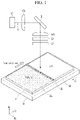
- a laser crystallization apparatus includes a light source unit LS, a first optical unit OP1, a second optical unit M, a third optical unit OP2, a fourth optical unit W1 and a fifth optical unit W2.
- a substrate 14 including an amorphous silicon thin film 16 is disposed on a transporting stage 18, and a laser beam 20 of a line type generated from the laser crystallization apparatus according to the present embodiment is irradiated to the amorphous silicon thin film 16 in a direction parallel to the third direction dz.
- the laser beam 20 forms a line across the transporting stage 18 from one side to an opposite side such that the laser beam 20 may be scanned along a length of the amorphous silicon thin film 16 in a scan direction.
- the position of the laser beam 20 is fixed, and the transporting stage 18 may move in the transporting direction a2. That is, by the movement of the transporting stage 18, the laser beam 20 scans the amorphous silicon thin film 16 to be irradiated in the scan direction which is in an opposite direction to the transporting direction a2, and the amorphous silicon of the scanned region 16a may be converted into poly crystalline silicon through a solidification process following melting by the laser beam 20.
- the laser beam 20 may have a line shape extending in the first direction (dx), and the crystallization operation that changes the amorphous silicon to the polycrystalline silicon may be uniformly done when the laser beam 20 of uniform intensity is irradiated along the first direction dx and caused to scan along the second direction dy.
- the first optical unit OP1 may be a long-axis lens
- the second optical unit M may be a mirror
- the third optical unit OP2 may be a short-axis lens
- the fourth optical unit W1 and the fifth optical unit W2 may be windows.
- the long-axis lens and/or the short-axis lens may be a condenser lens or an image formation lens, but embodiments are not limited thereto.
- the first optical unit OP1, the second optical unit M, the third optical unit OP2, the fourth optical unit W1, and the fifth optical unit W2 are not limited thereto and may be different optical apparatuses.
- the laser beam B supplied from the light source unit LS passes through the first optical unit OP1 and is condensed in a long-axis direction, and passes through the third optical unit OP2 and is diffused in a short-axis direction after the path thereof is converted in the second optical unit M to be supplied as the laser beam 20 of the line shape through the fourth optical unit W1 and the fifth optical unit W2.
- the laser beam B may include a plurality of collinear beams.
- the laser crystallization apparatus is described to include the first optical unit OP1, the second optical unit M, the third optical unit OP2, the fourth optical unit W1 and the fifth optical unit W2, however embodiments are not limited thereto.
- a plurality of different optical systems may be further included, and one or more of the first optical unit OP1, the second optical unit M, the third optical unit OP2, the fourth optical unit W1 and the fifth optical unit W2 may be omitted.
- FIG. 3 is a layout view of a laser crystallization apparatus according to an embodiment
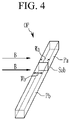
- FIG. 4 is a perspective view conceptually illustrating an optical unit of a laser crystallization apparatus of FIG. 3 .
- the laser crystallization apparatus includes the first optical unit OP1, the second optical unit M, the third optical unit OP2, the fourth optical unit W1, and the fifth optical unit W2 through which the laser beam B supplied from the light source unit LS passes.
- the first optical unit OP1 includes a first portion OP1a and a second portion OP1b.
- the first portion OP1a of the first optical unit OP1 and the second portion OP1b of the first optical unit OP1 are bonded to each other to form a bonded surface (which may also be described as a bonded part or bonded portion).
- the first portion OP1a of the first optical unit OP1 and the second portion OP1b of the first optical unit OP1 may be bonded to each other through optical contact bonding or welding.
- a first length La of the first portion OP1a of the first optical unit OP1 and a second length Lb of the second portion OP1b of the first optical unit OP1 may be different from each other, but embodiments are not limited thereto.
- the first length La of the first portion OP1a of the first optical unit OP1 and the second length Lb of the second portion OP1b of the first optical unit OP1 may be the same as each other.
- the first length La and the second length Lb are lengths measured based on a direction perpendicular to the direction in which the laser beam B is incident.
- the sum La+Lb of the first length La of the first portion OP1a of the first optical unit OP1 and the second length Lb of the second portion OP1b of the first optical unit OP1 may be about 2000 mm to 2500 mm.
- the bonded part of the first portion OP1a of the first optical unit OP1 and the second portion OP1b of the first optical unit OP1 may be parallel to the incidence direction of the laser beam B, at the bonded part of the first portion OP1a of the first optical unit OP1 and the second portion OP1b of the first optical unit OP1, and a width of the first portion OP1a of the first optical unit OP1 and a width of the second portion OP1b of the first optical unit OP1, which are measured in a direction parallel to the incident direction of the laser beam B, may be the same. Also, the widths of the first portion OP1a and second portion OP1b may vary as a surface of the first optical unit OP1 curves downward from a center to outward edges thereof.
- the second optical unit M includes a first portion Ma and a second portion Mb which are bonded to each other to form a bonded surface (which may also be described as a bonded part or bonded portion), and a first length La of the first portion Ma of the second optical unit M and a second length Lb of the second portion Mb of the second optical unit M may be different, but embodiments are not limited thereto.
- the first length La of the first portion Ma of the second optical unit M and the second length Lb of the second portion Mb of the second optical unit M may be the same as each other.
- the sum La+Lb of the first length La of the first portion Ma of the second optical unit M and the second length Lb of the second portion Mb of the second optical unit M may be about 2000 mm to 2500 mm.
- the first length La and the second length Lb are lengths measured based on a direction perpendicular to the direction in which the laser beam B is incident.
- the bonded part of the first portion Ma of the second optical unit M and the second portion Mb of the second optical unit M may be parallel to the incident direction of the laser beam B, at the bonded part of the first portion Ma of the second optical unit M and the second portion Mb of the second optical unit M.
- a width of the first portion Ma of the second optical unit M and the width of the second portion Mb of the second optical unit M, which are measured in the direction parallel to the incident direction of the laser beam B, may be the same.
- the third optical unit OP2 includes a first portion OP2a and a second portion OP2b bonded to each other to form a bonded surface (which may also be described as a bonded part or bonded portion), and a first length La of the first portion OP2a of the third optical unit OP2 and a second length Lb of the second portion OP2b of the third optical unit OP2 may be different, but embodiments are not limited thereto.
- the first length La of the first portion OP2a of the third optical unit OP2 and the second length Lb of the second portion OP2b of the third optical unit OP2 may be the same as each other.
- the sum La+Lb of the first length La of the first portion OP2a of the third optical unit OP2 and the second length Lb of the second portion OP2b of the third optical unit OP2 may be about 2000 mm to 2500 mm.
- the first length La and the second length Lb are lengths measured based on a direction perpendicular to the direction in which the laser beam B is incident.
- the bonded portion of the first portion OP2a of the third optical unit OP2 and the second portion OP2b of the third optical unit OP2 may be parallel to the incident direction of the laser beam B, at the bonded portion of the first portion OP2a of the third optical unit OP2 and the second portion OP2b of the third optical unit OP2, and a width of the first portion OP2a of the third optical unit OP2 and a width of the second portion OP2b of the third optical unit OP2, which are measured in the direction parallel to the incident direction of the laser beam B, may be the same as each other.
- the fourth optical unit W1 includes a first portion W1a and a second portion W1b bonded to each other to form a bonded surface (which may also be described as a bonded part or bonded portion), and a first length La of the first portion W1a of the fourth optical unit W1 and a second length Lb of the second portion W1b of the fourth optical unit W1 may be different, but embodiments are not limited thereto.
- the first length La of the first portion W1a of the fourth optical unit W1 and the second length Lb of the second portion W1b of the fourth optical unit W1 may be the same as each other.
- the sum La+Lb of the first length La of the first portion W1a of the fourth optical unit W1 and the second length Lb of the second portion W1b of the fourth optical unit W1 may be about 2000 mm to 2500 mm.
- the first length La and the second length Lb are lengths measured based on a direction perpendicular to the direction in which the laser beam B is incident.
- the bonded portion of the first portion W1a of the fourth optical unit W1 and the second portion W1b of the fourth optical unit W1 may be parallel to the incident direction of the laser beam B, and at the bonded portion of the first portion W1a of the fourth optical unit W1 and the second portion W1b of the fourth optical unit W1, a width of the first portion W1a of the fourth optical unit W1 and a width of the second portion W1b of the fourth optical unit W1, which are measured in the direction parallel to the incident direction of the laser beam B, may be the same as each other.
- the fifth optical unit W2 includes a first portion W2a and a second portion W2b bonded to each other to form a bonded surface (which may also be described as a bonded part or bonded portion), and a first length La of the first portion W2a of the fifth optical unit W2 and a second length Lb of the second portion W2b of the fifth optical unit W2 may be different, but embodiments are not limited thereto.
- the first length La of the first portion W2a of the fifth optical unit W2 and the second length Lb of the second portion W2b of the fifth optical unit W2 may be the same as each other.
- the sum La+Lb of the first length La of the first portion W2a of the fifth optical unit W2 and the second length Lb of the second portion W2b of the fifth optical unit W2 may be about 2000 mm to 2500 mm.
- the first length La and the second length Lb are lengths measured based on a direction perpendicular to the direction in which the laser beam B is incident.
- the bonded portion of the first portion W2a of the fifth optical unit W2 and the second portion W2b of the fifth optical unit W2 may be parallel to the incident direction of the laser beam B, and at the bonded portion of the first portion W2a of the fifth optical unit W2 and the second portion W2b of the fifth optical unit W2, a width of the first portion W2a of the fifth optical unit W2 and a width of the second portion W2b of the fifth optical unit W2, which are measured in a direction parallel to the incident direction of the laser beam B, may be the same as each other.
- the first length La of the first portion OP1a of the first optical unit OP1 may be different from or may be the same as the first length La of the first portion Ma of the second optical unit M.
- the second length Lb of the second portion OP1b of the first optical unit OP1 may be different from or may be the same as the second length Lb of the second portion Mb of the second optical unit M.
- the first length La of the first portion Ma of the second optical unit M may be different from or may be the same as the first length La of the first portion OP2a of the third optical unit OP2.
- the second length Lb of the second portion Mb of the second optical unit M may be different from or may be the same as the second length Lb of the second portion OP2b of the third optical unit OP2.
- the first length La of the first portion OP2a of the third optical unit OP2 may be different from or may be the same as the first length La of the first portion W1a of the fourth optical unit W1.
- the second length Lb of the second portion OP2b of the third optical unit OP2 may be different from or may be the same as the second length Lb of the second portion W1b of the fourth optical unit W1.
- the first length La of the first portion W1a of the fourth optical unit W1 may be different from or may be the same as the first length La of the first portion W2a of the fifth optical unit W2.
- the second length Lb of the second portion W1b of the fourth optical unit W1 may be different from or may be the same as the second length Lb of the second portion W2b of the fifth optical unit W2.
- the first length La of the first portion W2a of the fifth optical unit W2 may be different from or may be the same as the first length La of the first portion OP1a of the first optical unit OP1.
- the second length Lb of the second portion W2b of the fifth optical unit W2 may be different from or may be the same as the second length Lb of the second portion OP1b of the first optical unit OP1.
- each of the optical units OP1, M, OP2, W1, and W2 of the laser crystallization apparatus includes the first portion and the second portion bonded to each other, however it is not limited thereto, and at least one of the optical units OP1, M, OP2, W1, and W2 of the laser crystallization apparatus may include the first portion and the second portion bonded to each other.
- the optical units OP1, M, OP2, W1, and W2 of the laser crystallization apparatus according to the embodiment of FIG. 3 may have the same structure as the optical unit OP illustrated in FIG. 4 .
- the optical unit OP of the laser crystallization apparatus includes a first portion Pa and a second portion Pb bonded to each other to form a bonded surface (which may also be described as a bonded part or bonded portion).
- the first portion Pa and the second portion Pb of the optical unit OP may include or comprise glass.
- the first portion Pa and the second portion Pb of the optical unit OP may be bonded to each other at a boundary between the first portion Pa and the second portion Pb through a bonding element such as optical contact bonding or welding.
- a bonded surface Sab of the first portion Pa and the second portion Pb of the optical unit OP may be parallel to the incident direction of the laser beam B.
- the bonded surface Sab at the boundary between the first portion Pa and the second portion Pb includes a material layer combination that includes a part (e.g. a respective bonded surface) of the first portion Pa adjacent the boundary, the bonding element, and a part (e.g. a respective bonded surface) of the second portion Pb adjacent the boundary.
- the bonded surface Sab may have a thickness as described herein.
- a first width Wa of the first portion Pa and a second width Wb of the second portion Pb measured in a direction parallel to the incident direction of the laser beam B may be the same.
- the laser crystallization apparatus may irradiate a laser beam over a wide area, and for this purpose, the size of the optical unit of the laser crystallization apparatus may be increased.
- a manufacturing cost increases.
- the laser crystallization apparatus includes the optical unit including the first portion and the second portion bonded to each other, and the bonded portions of the first portion and the second portion may be bonded to each other through optical contact bonding or the welding. Accordingly, using bonded surfaces to join a plurality of smaller parts instead of requiring larger monolithic parts, it is possible to more easily diversify a shape and/or size of the optical units so as to form the laser crystallization apparatus including the optical units having large sizes without increasing the manufacturing cost of the laser crystallization apparatus.
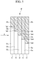
- FIG. 5 is a view illustrating an example of an optical unit of a laser crystallization apparatus according to an embodiment.
- the laser crystallization apparatus includes a plurality of optical units OP1, M, OP2, W1, and W2, and at least one among a plurality of optical units OP1, M, OP2, W1, and W2 of the laser crystallization apparatus may have a structure of the optical unit OP illustrated in FIG. 5 .
- the optical unit OP of the laser crystallization apparatus may include a plurality of sub-optical units O1, O2, O3, O4, and O5.
- the first sub-optical unit O1, the second sub-optical unit O2, the third sub-optical unit O3, the fourth sub-optical unit O4, and the fifth sub-optical unit O5 of the optical unit OP may be connected to each other.
- the first sub-optical unit O1 of the optical unit OP may include a first portion O1a and a second portion O1b bonded to each other
- the second sub-optical unit O2 of the optical unit OP may include a third portion O2a and a fourth portion O2b bonded to each other
- the third sub-optical unit O3 of the optical unit OP may include a fifth portion O3a and a sixth portion O3b bonded to each other
- the fourth sub-optical unit O4 of the optical unit OP may include a seventh portion O4a and an eighth portion O4b bonded to each other
- the fifth sub-optical unit O5 of the optical unit OP may include a ninth portion O5a and a tenth portion O5b bonded to each other.
- the first portion O1a and the second portion O1b of the first sub-optical unit O1 of the optical unit OP are bonded to each other to form a first bonded surface Sab1
- the third portion O2a and the fourth portion O2b of the second sub-optical unit O2 of the optical unit OP are bonded to each other to form a second bonded surface Sab2
- the fifth portion O3a and the sixth portion O3b of the third sub-optical unit O3 of the optical unit OP are bonded to each other to form a third bonded surface Sab3
- the seventh portion O4a and the eighth portion O4b of the fourth sub-optical unit O4 of the optical unit OP are bonded to each other to form a fourth bonded surface Sab4
- the ninth portion O5a and the tenth portion O5b of the fifth sub-optical unit O5 of the optical unit OP are bonded to each other to form a fifth bonded surface Sab5.
- the first bonded surface Sab1 of the first sub-optical unit O1 of the optical unit OP, the second bonded surface Sab2 of the second sub-optical unit O2 of the optical unit OP, the third bonded surface Sab3 of the third sub-optical unit O3 of the optical unit OP, the fourth bonded surface Sab4 of the fourth sub-optical unit O4 of the optical unit OP, and the fifth bonded surface Sab5 of the fifth sub-optical unit O5 of the optical unit OP may be parallel to the incident direction of the laser beam B on the optical unit OP.
- the first bonded surface Sab1 of the first sub-optical unit O1 of the optical unit OP, the second bonded surface Sab2 of the second sub-optical unit O2 of the optical unit OP, the third bonded surface Sab3 of the third sub-optical unit O3 of the optical unit OP, the fourth bonded surface Sab4 of the fourth sub-optical unit O4 of the optical unit OP, and the fifth bonded surface Sab5 of the fifth sub-optical unit O5 of the optical unit OP are not disposed in line with each other, but may be disposed to be offset from each other in a direction perpendicular to the incident direction of the laser beam B.
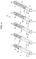
- FIG. 6 is an exploded perspective view of the optical unit of FIG. 5 .
- the optical unit OP of the laser crystallization apparatus includes a plurality of sub-optical units O1, O2, O3, O4, and O5.
- the first sub-optical unit O1 of the optical unit OP includes a first portion O1a and a second portion O1b bonded to each other on the first bonded surface Sab1, and a first length L01 of the first portion O1a of the first sub-optical unit O1 of the optical unit OP and a second length L11 of the second portion O1b of the first sub-optical unit O1 of the optical unit OP may be different from each other or may be the same.
- the first bonded surface Sab1 of the first sub-optical unit O1 of the optical unit OP may be a surface approximately parallel to the incident direction of the laser beam B. Based on the direction parallel to the incident direction of the laser beam B, a first width Wa of the first portion O1a of the first sub-optical unit O1 and a second width Wb of the second portion O1b of the first sub-optical unit O1 may be the same as each other on the first bonded surface Sab1.
- the second sub-optical unit O2 of the optical unit OP includes a third portion O2a and a fourth portion O2b bonded to each other on the second bonded surface Sab2, and a third length L02 of the third portion O2a of the second sub-optical unit O2 of the optical unit OP and a fourth length L12 of the fourth portion O2b of the second sub-optical unit O2 of the optical unit OP may be different from or the same as each other.
- the second bonded surface Sab2 of the second sub-optical unit O2 of the optical unit OP may be a surface approximately parallel to the incident direction of the laser beam B. Based on the direction parallel to the incident direction of the laser beam B, a first width Wa of the third portion O2a of the second sub-optical unit O2 and a second width Wb of the fourth portion O2b of the second sub-optical unit O2 may be the same as each other on the second bonded surface Sab2.
- the third sub-optical unit O3 of the optical unit OP may include a fifth portion O3a and the sixth portion O3b bonded to each other on the third bonded surface Sab3, and a fifth length L03 of the fifth portion O3a of the third sub-optical unit O3 of the optical unit OP and a sixth length L13 of the sixth portion O3b of the third sub-optical unit O3 of the optical unit OP may be different from or the same as each other.
- the third bonded surface Sab3 of the third sub-optical unit O3 of the optical unit OP may be a surface approximately parallel to the incident direction of the laser beam B. Based on the direction parallel to the incident direction of the laser beam B, a first width Wa of the fifth portion O3a of the third sub-optical unit O3 and tahe second width Wb of the sixth portion O3b of the third sub-optical unit O3 may be the same as each other on the third bonded surface Sab3.
- the fourth sub-optical unit O4 of the optical unit OP includes a seventh portion O4a and an eighth portion O4b bonded to each other on the fourth bonded surface Sab4, and a seventh length L04 of the seventh portion O4a of the fourth sub-optical unit O4 of the optical unit OP and an eighth length L14 of the eighth portion O4b of the fourth sub-optical unit O4 of the optical unit OP may be different from or the same as each other.
- the fourth bonded surface Sab4 of the fourth sub-optical unit O4 of the optical unit OP may be a surface approximately parallel to the incident direction of the laser beam B. Based on the direction parallel to the incident direction of the laser beam B, a first width Wa of the seventh portion O4a of the fourth sub-optical unit O4 and a second width Wb of the eighth portion O4b of the fourth sub-optical unit O4 may be the same as each other on the fourth bonded surface Sab4.
- the fifth sub-optical unit O5 of the optical unit OP may include a ninth portion O5a and a tenth portion O5b bonded to each other on the fifth bonded surface Sab5, and a ninth length L05 of the ninth portion O5a of the fifth sub-optical unit O5 of the optical unit OP and a tenth length L15 of the tenth portion O5b of the fifth sub-optical unit O5 of the optical unit OP may be different from or the same as each other.
- the fifth bonded surface Sab5 of the fifth sub-optical unit O5 of the optical unit OP may be a surface approximately parallel to the incident direction of the laser beam B. Based on the direction parallel to the incident direction of the laser beam B, a first width Wa of the ninth portion O5a of the fifth sub-optical unit O5 and a second width Wb of the tenth portion O5b of the fifth sub-optical unit O5 may be the same as each other on the fifth bonded surface Sab5.
- the first length L01 of the first portion O1a of the first sub-optical unit O1 of the optical unit OP, the third length L02 of the third portion O2a of the second sub-optical unit O2 of the optical unit OP, the fifth length L03 of the fifth portion O3a of the third sub-optical unit O3 of the optical unit OP, the seventh length L04 of the seventh portion O4a of the fourth sub-optical unit O4 of the optical unit OP, and the ninth length L05 of the ninth portion O5a of the fifth sub-optical unit O5 of the optical unit OP may be different from each other.
- the first length L01, the third length L02, the fifth length L03, the seventh length L04, and the ninth length L05 may be lengths measured in the direction perpendicular to the incident direction of the laser beam B.
- the second length L11 of the second portion O1b of the first sub-optical unit O1 of the optical unit OP, the fourth length L12 of the fourth portion O2b of the second sub-optical unit O2 of the optical unit OP, the sixth length L13 of the sixth portion O3b of the third sub-optical unit O3 of the optical unit OP, the eighth length L14 of the eighth portion O4b of the fourth sub-optical unit O4 of the optical unit OP, and the tenth length L15 of the tenth portion O5b of the fifth sub-optical unit O5 of the optical unit OP may be different from each other.
- the second length L11, the fourth length L12, the sixth length L13, the eighth length L14, and the tenth length L15 may be lengths measured in the direction perpendicular to the incident direction of the laser beam B.
- the first portion O1a and the second portion O1b of the first sub-optical unit O1 of the optical unit OP may be bonded to each other through optical contact bonding or welding
- the third portion O2a and the fourth portion O2b of the second sub-optical unit O2 of the optical unit OP may be bonded to each other through optical contact bonding or welding
- the fifth portion O3a and the sixth portion O3b of the third sub-optical unit O3 of the optical unit OP may be bonded to each other through optical contact bonding or welding
- the seventh portion O4a and the eighth portion O4b of the fourth sub-optical unit O4 of the optical unit OP may be bonded to each other through optical contact bonding or welding
- the ninth portion O5a and the tenth portion O5b of the fifth sub-optical unit O5 of the optical unit OP may be bonded to each other through optical contact bonding or welding.
- the first sub-optical unit O1, the second sub-optical unit O2, the third sub-optical unit O3, the fourth sub-optical unit O4, and the fifth sub-optical unit O5 of the optical unit OP may be sequentially disposed along the direction parallel to the incident direction of the laser beam B, and the first sub-optical unit O1, the second sub-optical unit O2, the third sub-optical unit O3, the fourth sub-optical unit O4, and the fifth sub-optical unit O5 of the optical unit OP may be bonded to each other through optical contact bonding or welding.
- the first bonded surface Sab1 of the first sub-optical unit O1 of the optical unit OP, the second bonded surface Sab2 of the second sub-optical unit O2 of the optical unit OP, the third bonded surface Sab3 of the third sub-optical unit O3 of the optical unit OP, the fourth bonded surface Sab4 of the fourth sub-optical unit O4 of the optical unit OP, and the fifth bonded surface Sab5 of the fifth sub-optical unit O5 of the optical unit OP are not disposed in a line with each other, but may be disposed to be offset from each other in a direction perpendicular to the incident direction of the laser beam B.
- the optical unit of the laser crystallization apparatus includes five sub-optical units O1, O2, O3, O4, and O5, however it is not limited thereto, and the number of the plurality of sub-optical units may be changed.
- FIG. 7 is a graph conceptually illustrating changes in intensity of a laser beam passing through an optical unit of a laser crystallization apparatus according to an embodiment.
- the intensity BL of the laser beam B may be reduced on the first bonded surface Sab1 of the first sub-optical unit O1 of the optical unit OP, the second bonded surface Sab2 of the second sub-optical unit O2 of the optical unit OP, the third bonded surface Sab3 of the third sub-optical unit O3 of the optical unit OP, the fourth bonded surface Sab4 of the fourth sub-optical unit O4 of the optical unit OP, and the fifth bonded surface Sab5 of the fifth sub-optical unit O5 of the optical unit OP.
- the first bonded surface Sab1 of the first sub-optical unit O1 of the optical unit OP, the second bonded surface Sab2 of the second sub-optical unit O2 of the optical unit OP, the third bonded surface Sab3 of the third sub-optical unit O3 of the optical unit OP, the fourth bonded surface Sab4 of the fourth sub-optical unit O4 of the optical unit OP, and the fifth bonded surface Sab5 of the fifth sub-optical unit O5 of the optical unit OP are not disposed in line with each other, but are disposed to be offset from each other, the first bonded surface Sab1, the second bonded surface Sab2, the third bonded surface Sab3, the fourth bonded surface Sab4, and the fifth bonded surface Sab5, in which the intensity BL of the laser beam B is changed, do not overlap each other.
- the change of the intensity BL of the laser beam B passing through the optical unit OP is not concentrated at a specific position, and therefore by spacing the bonded surfaces evenly about the width of the laser beam B, the intensity of a uniform laser beam B may be supplied evenly to the substrate 14 according to the positions of the bonded surfaces.
- FIG. 8 is a view illustrating one example of an optical unit of a laser crystallization apparatus according to another embodiment.
- the laser crystallization apparatus includes a plurality of optical units OP1, M, OP2, W1, and W2, and at least one among the plurality of optical units OP1, M, OP2, W1, and W2 of the laser crystallization apparatus may have the structure of the optical unit OP illustrated in FIG. 8 .
- the optical unit OP of the laser crystallization apparatus may include a plurality of sub-optical units O1, O2, O3, O4, and O5 separated from each other.
- the first sub-optical unit O1 of the optical unit OP may include a first portion O1a and a second portion O1b bonded to each other
- the second sub-optical unit O2 of the optical unit OP may include a third portion O2a and a fourth portion O2b bonded to each other
- the third sub-optical unit O3 of the optical unit OP may include a fifth portion O3a and a sixth portion O3b bonded to each other
- the fourth sub-optical unit O4 of the optical unit OP may include a seventh portion O4a and an eighth portion O4b bonded to each other
- the fifth sub-optical unit O5 of the optical unit OP may include a ninth portion O5a and a tenth portion O5b bonded to each other.
- the first portion O1a and the second portion O1b of the first sub-optical unit O1 of the optical unit OP are bonded to each other on the first bonded surface Sab1
- the third portion O2a and the fourth portion O2b of the second sub-optical unit O2 of the optical unit OP are bonded to each other on the second bonded surface Sab2
- the fifth portion O3a and the sixth portion O3b of the third sub-optical unit O3 of the optical unit OP are bonded to each other on the third bonded surface Sab3
- the seventh portion O4a and the eighth portion O4b of the fourth sub-optical unit O4 of the optical unit OP are bonded to each other on the fourth bonded surface Sab4
- the ninth portion O5a and the tenth portion O5b of the fifth sub-optical unit O5 of the optical unit OP are bonded to each other on the fifth bonded surface Sab5.
- the first bonded surface Sab1 of the first sub-optical unit O1 of the optical unit OP, the second bonded surface Sab2 of the second sub-optical unit O2 of the optical unit OP, the third bonded surface Sab3 of the third sub-optical unit O3 of the optical unit OP, the fourth bonded surface Sab4 of the fourth sub-optical unit O4 of the optical unit OP, and the fifth bonded surface Sab5 of the fifth sub-optical unit O5 of the optical unit OP may be respectively parallel to the incident direction of the laser beam B incident to the optical unit OP.
- the first bonded surface Sab1 of the first sub-optical unit O1 of the optical unit OP, the second bonded surface Sab2 of the second sub-optical unit O2 of the optical unit OP, the third bonded surface Sab3 of the third sub-optical unit O3 of the optical unit OP, the fourth bonded surface Sab4 of the fourth sub-optical unit O4 of the optical unit OP, and the fifth bonded surface Sab5 of the fifth sub-optical unit O5 of the optical unit OP are not disposed in a line with each other, but may be disposed to be offset from each other in a direction perpendicular to the emission of the laser beam B.
- the optical unit of the laser crystallization apparatus includes the five sub-optical units O1, O2, O3, O4, and O5, however it is not limited thereto, and the number of the plurality of sub-optical units may be changed.
- optical units of the laser crystallization apparatuses may be applied to the optical unit of the laser crystallization apparatus according to the present embodiment.
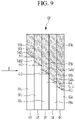
- FIG. 9 is a view illustrating one example of an optical unit of a laser crystallization apparatus according to another embodiment.
- the laser crystallization apparatus includes a plurality of optical units OP1, M, OP2, W1, and W2, and at least one among the plurality of optical units OP1, M, OP2, W1, and W2 of the laser crystallization apparatus may have the structure of the optical unit OP illustrated in FIG. 9 .
- the optical unit OP of the laser crystallization apparatus may include a plurality of sub-optical units O1, O2, O3, O4, and O5.
- the first sub-optical unit O1, the second sub-optical unit O2, the third sub-optical unit O3, the fourth sub-optical unit O4, and the fifth sub-optical unit O5 may be sequentially disposed according to the direction parallel to the incident direction of the laser beam B of the optical unit OP.
- the first sub-optical unit O1 of the optical unit OP may include a first portion O1a and a second portion O1b bonded to each other
- the second sub-optical unit O2 of the optical unit OP may include a third portion O2a and a fourth portion O2b bonded to each other
- the third sub-optical unit O3 of the optical unit OP may include a fifth portion O3a and a sixth portion O3b bonded to each other
- the fourth sub-optical unit O4 of the optical unit OP may include a seventh portion O4a and an eighth portion O4b bonded to each other
- the fifth sub-optical unit O5 of the optical unit OP may include a ninth portion O5a and a tenth portion O5b bonded to each other.
- the first portion O1a and the second portion O1b of the first sub-optical unit O1 of the optical unit OP are bonded to each other on the first bonded surface Sab1
- the third portion O2a and the fourth portion O2b of the second sub-optical unit O2 of the optical unit OP are bonded to each other on the second bonded surface Sab2
- the fifth portion O3a and the sixth portion O3b of the third sub-optical unit O3 of the optical unit OP are bonded to each other on the third bonded surface Sab3
- the seventh portion O4a and the eighth portion O4b of the fourth sub-optical unit O4 of the optical unit OP are bonded to each other on the fourth bonded surface Sab4
- the ninth portion O5a and the tenth portion O5b of the fifth sub-optical unit O5 of the optical unit OP are bonded to each other on the fifth bonded surface Sab5.
- the bonded surfaces Sab at the boundaries between the respective portions include a material composition including a part of a first portion adjacent the boundary, the bonding element, and a part of a second portion adjacent the boundary extending perpendicular to the incident direction of the laser beam B.
- the first bonded surface Sab1 of the first sub-optical unit O1 of the optical unit OP may form a first angle ⁇ 1 with the incident direction of the laser beam B
- the second bonded surface Sab2 of the second sub-optical unit O2 of the optical unit OP may form a second angle ⁇ 2 with the incident direction of the laser beam B
- the third bonded surface Sab3 of the third sub-optical unit O3 of the optical unit OP may form a third angle ⁇ 3 with the incident direction of the laser beam B
- the fourth bonded surface Sab4 of the fourth sub-optical unit O4 of the optical unit OP may form a fourth angle ⁇ 4 with the incident direction of the laser beam B
- the fifth bonded surface Sab5 of the fifth sub-optical unit O5 of the optical unit OP may form a fifth angle ⁇ 5 with the incident direction of the laser beam B.
- the first angle ⁇ 1, the second angle ⁇ 2, the third angle ⁇ 3, the fourth angle ⁇ 4, and the fifth angle ⁇ 5 may be smaller than about 45 degrees, and may be equal to or different from each other.
- the first bonded surface Sab1 of the first sub-optical unit O1 of the optical unit OP, the second bonded surface Sab2 of the second sub-optical unit O2 of the optical unit OP, the third bonded surface Sab3 of the third sub-optical unit O3 of the optical unit OP, the fourth bonded surface Sab4 of the fourth sub-optical unit O4 of the optical unit OP, and the fifth bonded surface Sab5 of the fifth sub-optical unit O5 of the optical unit OP are not disposed in a line with each other, but may be disposed to be offset from each other in a direction perpendicular to the incident direction of the laser beam B.
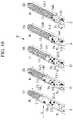
- FIG. 10 is an exploded perspective view of the optical unit of FIG. 9 .
- the optical unit OP of the laser crystallization apparatus includes a plurality of sub-optical units O1, O2, O3, O4, and O5.
- the first sub-optical unit O1 of the optical unit OP includes the first portion O1a and the second portion O1b bonded to each other on the first bonded surface Sab1, and a first length L01 of a first surface of the first portion O1a of the first sub-optical unit O1 and a second length L11 of a first surface of the second portion O1b may be different, respectively, from a first length (L01-L) of a second surface opposite to the first surface of the first portion O1a of the first sub-optical unit O1 and a second length (L11+L) of a second surface opposite to the first surface of the second portion O1b of the first sub-optical unit O1.
- the first length L01-L of the second surface of the first portion O1a of the first sub-optical unit O1 may be shorter by a length difference L than the first length L01 of the first surface of the first portion O1a of the first sub-optical unit O1.
- the second length L11+L of the second surface of the second portion O1b of the first sub-optical unit O1 may be longer by the length difference L than the second length L11 of the first surface of the second portion O1b of the first sub-optical unit O1. That is, based on the direction perpendicular to the incident direction of the laser beam B, the width of the first bonded surface Sab1 of the first sub-optical unit O1 may be the same as the length difference L.
- the length difference L and the width of the first bonded surface Sab1 may be about 0.3 % to about 0.6 % of an entire length of the first sub-optical unit O1.
- the entire length of the first sub-optical unit O1 may be about 2200 mm
- the length difference L and the width of the first bonded surface Sab1 may be about 10 mm.
- the width of the first bonded surface Sab1 refers to a combined width including part of the first portion O1a, part of the second portion O1b, and a bonding element area at the boundary of the first portion O1a and the second portion O1b. This composition is representative of the other bonded surfaces discussed herein.
- lengths are measured in the direction perpendicular to the incident direction of the laser beam B.
- the first bonded surface Sab1 of the first sub-optical unit O1 of the optical unit OP may form the first angle ⁇ 1 with the incident direction of the laser beam B, and based on the direction parallel to the incident direction of the laser beam B, the first width Wa of the first portion O1a of the first sub-optical unit O1 and the second width Wb of the second portion O1b of the first sub-optical unit O1 may be the same as each other on the first bonded surface Sab1.
- the second sub-optical unit O2 of the optical unit OP includes the third portion O2a and the fourth portion O2b bonded to each other on the second bonded surface Sab2, and a third length L02 of a first surface of the third portion O2a of the second sub-optical unit O2 and a fourth length L12 of a first surface of the fourth portion O2b of the second sub-optical unit O2 may be different, respectively, from a third length L02-L of a second surface of the third portion O2a of the second sub-optical unit O2 and a fourth length L12+L of a second surface of the fourth portion O2b of the second sub-optical unit O2 by the length difference L. That is, based on the direction perpendicular to the incident direction of the laser beam B, on the second sub-optical unit O2, a width of the second bonded surface Sab2 may be the same as the length difference L.
- the length difference L and the width of the second bonded surface Sab2 may be about 0.3 % to about 0.6 % of an entire length of the second sub-optical unit O2.
- the length difference L and the width of the second bonded surface Sab2 may be about 10 mm.
- the above-described lengths are the lengths measured in the direction perpendicular to the incident direction of the laser beam B.
- the second bonded surface Sab2 of the second sub-optical unit O2 of the optical unit OP may form the second angle ⁇ 2 with the incident direction of the laser beam B, and based on the direction parallel to the incident direction of the laser beam B, a first width Wa of the third portion O2a of the second sub-optical unit O2 and a second width Wb of the fourth portion O2b of the second sub-optical unit O2 may be the same as each other on the second bonded surface Sab2.
- the third sub-optical unit O3 of the optical unit OP includes the fifth portion O3a and the sixth portion O3b bonded to each other on the third bonded surface Sab3, and a fifth length L03 of a first surface of the fifth portion O3a of the third sub-optical unit O3 and a sixth length L13 of a first surface of the sixth portion O3b of the third sub-optical unit O3 may be different, respectively, from a fifth length L03-L of a second surface of the fifth portion O3a of the third sub-optical unit O3 and a sixth length L13+L of a second surface of the sixth portion O3b of the third sub-optical unit O3 by the length difference L. That is, based on the direction perpendicular to the incident direction of the laser beam B, on the third sub-optical unit O3, a width of the third bonded surface Sab3 may be the same as the length difference L.
- the length difference L and the width of the third bonded surface Sab3 may be about 0.3 % to about 0.6 % of the entire length of the third sub-optical unit O3.
- the length difference L and the width of the third bonded surface Sab3 may be about 10 mm.
- All lengths described above are lengths measured in the direction perpendicular to the direction in which the laser beam B is incident.
- the third bonded surface Sab3 of the third sub-optical unit O3 of the optical unit OP may form the third angle ⁇ 3 with the incident direction of the laser beam B, and based on the direction parallel to the incident direction of the laser beam B, a first width Wa of the fifth portion O3a of the third sub-optical unit O3 and a second width Wb of the sixth portion O3b of the third sub-optical unit O3 may be the same as each other on the third bonded surface Sab3.
- the fourth sub-optical unit O4 of the optical unit OP includes the seventh portion O4a and the eighth portion O4b bonded to each other on the fourth bonded surface Sab4, and a seventh length L04 of a first surface of the seventh portion O4a of the fourth sub-optical unit O4 and an eighth length L14 of a first surface of the eighth portion O4b of the fourth sub-optical unit O4 may be different, respectively, from a seventh length L04-L of a second surface seventh portion O4a of the fourth sub-optical unit O4 and an eighth length L14+L of a second surface of the eighth portion O4b of the fourth sub-optical unit O4 by the length difference L. That is, based on the direction perpendicular to the incident direction of the laser beam B, a width of the fourth bonded surface Sab4 may be the same as the length difference L on the fourth sub-optical unit O4.
- the length difference L and the width of the fourth bonded surface Sab4 may be about 0.3 % to about 0.6 % of an entire length of the fourth sub-optical unit O4.
- the length difference L and the width of the fourth bonded surface Sab4 may be about 10 mm.
- All lengths described above are lengths measured in the direction perpendicular to the direction in which the laser beam B is incident.
- the fourth bonded surface Sab4 of the fourth sub-optical unit O4 of the optical unit OP may form the fourth angle ⁇ 4 with the incident direction of the laser beam B, and based on the direction parallel to the incident direction of the laser beam B, a first width Wa of the seventh portion O4a of the fourth sub-optical unit O4 and a second width Wb of the eighth portion O4b of the fourth sub-optical unit O4 may be the same as each other on the fourth bonded surface Sab4.
- the fifth sub-optical unit O5 of the optical unit OP includes the ninth portion O5a and the tenth portion O5b bonded to each other on the fifth bonded surface Sab5, and a ninth length L05 of a first surface of the ninth portion O5a of the fifth sub-optical unit O5 and a tenth length L15 of a first surface tenth portion O5b of the fifth sub-optical unit O5 may be different, respectively, from a ninth length L05-L of a second surface of the ninth portion O5a of the fifth sub-optical unit O5 and a tenth length L15+L of a second surface of the tenth portion O5b of the fifth sub-optical unit O5 by the length difference L. That is, based on the direction perpendicular to the direction in which the laser beam B is incident, a width of the fifth bonded surface Sab5 may be equal to the length difference L on the fifth sub-optical unit O5.
- the length difference L and the width of the fifth bonded surface Sab5 may be about 0.3 % to about 0.6 % of an entire length of the fifth sub-optical unit O5.
- the length difference L and the width of the fifth bonded surface Sab5 may be about 10 mm.
- All lengths described above are lengths measured in the direction perpendicular to the direction in which the laser beam B is incident.
- the fifth bonded surface Sab5 of the fifth sub-optical unit O5 of the optical unit OP may form the fifth angle ⁇ 5 with the incident direction of the laser beam B, and based on the direction parallel to the incident direction of the laser beam B, a first width Wa of the ninth portion O5a of the fifth sub-optical unit O5 and a second width Wb of the tenth portion O5b of the fifth sub-optical unit O5 may be the same as each other on the fifth bonded surface Sab5.
- the first length L01 of the first portion O1a of the first sub-optical unit O1 of the optical unit OP, the third length L02 of the third portion O2a of the second sub-optical unit O2 of the optical unit OP, the fifth length L03 of the fifth portion O3a of the third sub-optical unit O3 of the optical unit OP, the seventh length L04 of the seventh portion O4a of the fourth sub-optical unit O4 of the optical unit OP, and the ninth length L05 of the ninth portion O5a of the fifth sub-optical unit O5 of the optical unit OP may be different from each other.
- the first length L01, the third length L02, the fifth length L03, the seventh length L04, and the ninth length L05 may be lengths measured in the direction perpendicular to the incident direction of the laser beam B.
- the second length L11 of the second portion O1b of the first sub-optical unit O1 of the optical unit OP, the fourth length L12 of the fourth portion O2b of the second sub-optical unit O2 of the optical unit OP, the sixth length L13 of the sixth portion O3b of the third sub-optical unit O3 of the optical unit OP, the eighth length L14 of the eighth portion O4b of the fourth sub-optical unit O4 of the optical unit OP, and the tenth length L15 of the tenth portion O5b of the fifth sub-optical unit O5 of the optical unit OP may be different from each other.
- the second length L11, the fourth length L12, the sixth length L13, the eighth length L14, and the tenth length L15 may be lengths measured in the direction perpendicular of the incident direction of the laser beam B.
- the first portion O1a and the second portion O1b of the first sub-optical unit O1 of the optical unit OP may be bonded to each other through optical contact bonding or welding
- the third portion O2a and the fourth portion O2b of the second sub-optical unit O2 of the optical unit OP may be bonded to each other through optical contact bonding or welding
- the fifth portion O3a and the sixth portion O3b of the third sub-optical unit O3 of the optical unit OP may be bonded to each other through optical contact bonding or welding
- the seventh portion O4a and the eighth portion O4b of the fourth sub-optical unit O4 of the optical unit OP may be bonded to each other through optical contact bonding or welding
- the ninth portion O5a and the tenth portion O5b of the fifth sub-optical unit O5 of the optical unit OP may be bonded to each other through optical contact bonding or welding.
- the first sub-optical unit O1, the second sub-optical unit O2, the third sub-optical unit O3, the fourth sub-optical unit O4, and the fifth sub-optical unit O5 of the optical unit OP may be sequentially disposed along the direction parallel to the incident direction of the laser beam B, and the first sub-optical unit O1, the second sub-optical unit O2, the third sub-optical unit O3, the fourth sub-optical unit O4, and the fifth sub-optical unit O5 of the optical unit OP may be bonded to each other through optical contact bonding or welding.
- the first bonded surface Sab1 of the first sub-optical unit O1 of the optical unit OP, the second bonded surface Sab2 of the second sub-optical unit O2 of the optical unit OP, the third bonded surface Sab3 of the third sub-optical unit O3 of the optical unit OP, the fourth bonded surface Sab4 of the fourth sub-optical unit O4 of the optical unit OP, and the fifth bonded surface Sab5 of the fifth sub-optical unit O5 of the optical unit OP are not disposed in a line with each other, but may be disposed to be offset from each other in a direction perpendicular to the incident direction of the laser beam B.
- the optical unit of the laser crystallization apparatus includes five sub-optical units O1, O2, O3, O4, and O5, however it is not limited thereto, and the number of the plurality of sub-optical units may be changed.
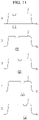
- FIG. 11 is a graph conceptually illustrating changes in intensity of a laser beam passing through an optical unit of a laser crystallization apparatus according to another embodiment.
- the intensity BL of the laser beam B may be reduced in the first bonded surface Sab1 of the first sub-optical unit O1 of the optical unit OP, the second bonded surface Sab2 of the second sub-optical unit O2 of the optical unit OP, the third bonded surface Sab3 of the third sub-optical unit O3 of the optical unit OP, the fourth bonded surface Sab4 of the fourth sub-optical unit O4 of the optical unit OP, and the fifth bonded surface Sab5 of the fifth sub-optical unit O5 of the optical unit OP.
- the first bonded surface Sab1 of the first sub-optical unit O1 of the optical unit OP, the second bonded surface Sab2 of the second sub-optical unit O2 of the optical unit OP, the third bonded surface Sab3 of the third sub-optical unit O3 of the optical unit OP, the fourth bonded surface Sab4 of the fourth sub-optical unit O4 of the optical unit OP, and the fifth bonded surface Sab5 of the fifth sub-optical unit O5 of the optical unit OP are not disposed in one line and are disposed to be offset from each other, the first bonded surface Sab1, the second bonded surface Sab2, the third bonded surface Sab3, the fourth bonded surface Sab4, and the fifth bonded surface Sab5, in which the intensity BL of the laser beam B is changed, do not overlap each other.
- the change of the intensity BL of the laser beam B passing through the optical unit OP is not concentrated at a specific position, therefore a uniform laser beam B may be supplied substantially evenly to the substrate 14 according to the position of the bonded surfaces.
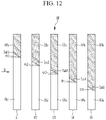
- FIG. 12 is a view illustrating an example of an optical unit of a laser crystallization apparatus according to another embodiment.
- the laser crystallization apparatus includes a plurality of optical units OP1, M, OP2, W1, and W2, and at least one among the plurality of optical units OP1, M, OP2, W1, and W2 of the laser crystallization apparatus may have the structure of the optical unit OP illustrated in FIG. 12 .
- the optical unit OP of the laser crystallization apparatus may include a plurality of sub-optical units O1, O2, O3, O4, and O5 separated from each other.
- the first sub-optical unit O1 of the optical unit OP may include a first portion O1a and a second portion O1b bonded to each other
- the second sub-optical unit O2 of the optical unit OP may include a third portion O2a and a fourth portion O2b bonded to each other
- the third sub-optical unit O3 of the optical unit OP may include a fifth portion O3a and a sixth portion O3b bonded to each other
- the fourth sub-optical unit O4 of the optical unit OP may include a seventh portion O4a and an eighth portion O4b bonded to each other
- the fifth sub-optical unit O5 of the optical unit OP may include a ninth portion O5a and a tenth portion O5b bonded to each other.
- the first portion O1a and the second portion O1b of the first sub-optical unit O1 of the optical unit OP are bonded to each other on a first bonded surface Sab1
- the third portion O2a and the fourth portion O2b of the second sub-optical unit O2 of the optical unit OP are bonded to each other on a second bonded surface Sab2
- the fifth portion O3a and the sixth portion O3b of the third sub-optical unit O3 of the optical unit OP are bonded to each other on a third bonded surface Sab3
- the seventh portion O4a and the eighth portion O4b of the fourth sub-optical unit O4 of the optical unit OP are bonded to each other on a fourth bonded surface Sab4
- the ninth portion O5a and the tenth portion O5b of the fifth sub-optical unit O5 of the optical unit OP are bonded to each other on a fifth bonded surface Sab5.
- the first bonded surface Sab1 of the first sub-optical unit O1 of the optical unit OP, the second bonded surface Sab2 of the second sub-optical unit O2 of the optical unit OP, the third bonded surface Sab3 of the third sub-optical unit O3 of the optical unit OP, the fourth bonded surface Sab4 of the fourth sub-optical unit O4 of the optical unit OP, and the fifth bonded surface Sab5 of the fifth sub-optical unit O5 of the optical unit OP may respectively form a first angle ⁇ 1, a second angle ⁇ 2, a third angle ⁇ 3, a fourth angle ⁇ 4, and a fifth angle ⁇ 5 with the incident direction of the laser beam B incident to the optical unit OP.
- the first angle ⁇ 1, the second angle ⁇ 2, the third angle ⁇ 3, the fourth angle ⁇ 4, and the fifth angle ⁇ 5 may be the same as or different from each other.
- the first bonded surface Sab1 of the first sub-optical unit O1 of the optical unit OP, the second bonded surface Sab2 of the second sub-optical unit O2 of the optical unit OP, the third bonded surface Sab3 of the third sub-optical unit O3 of the optical unit OP, the fourth bonded surface Sab4 of the fourth sub-optical unit O4 of the optical unit OP, and the fifth bonded surface Sab5 of the fifth sub-optical unit O5 of the optical unit OP are not disposed in a line with each other, but may be disposed to be offset from each other in a direction perpendicular to the incident direction of the laser beam B.
- the optical unit of the laser crystallization apparatus incudes five sub-optical units O1, O2, O3, O4, and O5, however it is not limited thereto, and the number of the plurality of sub-optical units may be changed.
- optical units of the laser crystallization apparatus are applicable to all of the optical units of the laser crystallization apparatus according to the present embodiment.
- the laser crystallization apparatuses include a plurality of optical units, and at least one among the plurality of optical units includes a first portion and a second portion bonded to each other, at least one among the plurality of optical units may include a plurality of sub-optical units including the first portion and the second portion bonded to each other, and the plurality of sub-optical units may be bonded to each other or separated from each other.
- the bonded surfaces of each of the plurality of sub-optical units may be disposed to be deviated or offset from each other without being disposed in one line along the direction parallel to the incident direction of the laser beam. Accordingly, it is possible to form the laser crystallization apparatus including the optical unit having a large size without increasing the manufacturing cost of the laser crystallization apparatus and without reducing the uniformity of the laser beam.
Landscapes
- Physics & Mathematics (AREA)
- Optics & Photonics (AREA)
- Engineering & Computer Science (AREA)
- Chemical & Material Sciences (AREA)
- Mechanical Engineering (AREA)
- Plasma & Fusion (AREA)
- General Physics & Mathematics (AREA)
- Crystallography & Structural Chemistry (AREA)
- Organic Chemistry (AREA)
- Nonlinear Science (AREA)
- Materials Engineering (AREA)
- Metallurgy (AREA)
- Manufacturing & Machinery (AREA)
- Chemical Kinetics & Catalysis (AREA)
- General Chemical & Material Sciences (AREA)
- Oil, Petroleum & Natural Gas (AREA)
- Inorganic Chemistry (AREA)
- Laser Beam Processing (AREA)
- Recrystallisation Techniques (AREA)
Abstract
Description
- Embodiments of the invention relate generally to a laser crystallization apparatus.
- A liquid crystal display (LCD) and an organic light emitting diode (OLED) display, which are types of flat panel display devices, can be fabricated to be thin and light, so they are commonly used as a display device for mobile electronic devices, and their application coverage is being extended to large-scale display devices. In particular, as the necessity for a display device requiring high speed operational characteristics emerges, research for such a display device is actively ongoing.
- In order to satisfy the high speed operational characteristics of a display device, a channel region of a thin film transistor (TFT) is formed by using polycrystalline silicon instead of amorphous silicon.
- As a method of forming polycrystalline silicon, an annealing method using a laser has been disclosed.
- Meanwhile, as a glass substrate for forming the display device is becoming larger, it is important to irradiate a laser beam over a wide area.
- The above information disclosed in this Background section is only for understanding of the background of the inventive concepts, and, therefore, it may contain information that does not constitute prior art.
- An embodiment is to provide a laser crystallization apparatus capable of irradiating a laser beam to a large area without increasing a manufacturing cost.
- Additional features of the inventive concepts will be set forth in the description which follows, and in part will be apparent from the description, or may be learned by practice of the inventive concepts.
- A laser crystallization apparatus according to an embodiment includes a light source unit configured to irradiate a laser beam; and an optical unit to which the laser beam is incident, in use, in an incident direction. The optical unit includes a first portion and a second portion bonded to each other to form a bonded surface, and a first width of the first portion and a second width of the second portion are the same as each other at the bonded surface based on a direction parallel to the incident direction of the laser beam (e.g. as measured in a direction parallel to the incident direction of the laser beam).
- Based on a direction perpendicular to the incident direction of the laser beam, a first length of the first portion and a second length of the second portion may be different from each other.
- The first portion and the second portion may be bonded by optical contact bonding or welding.
- The bonded surface may be parallel to the incident direction of the laser beam.
- The bonded surface may be inclined to form a predetermined angle with the incident direction of the laser beam.
- Based on a direction perpendicular to the incident direction of the laser beam, the width of the bonded surface may be about 0.3 % to about 0.6 % of a length of the optical unit.
- The length of the optical unit may be about 2000 mm to about 2500 mm based on the direction perpendicular to the incident direction of the laser beam.
- A laser crystallization apparatus according to another embodiment includes a light source unit configured to irradiate a laser beam; and an optical unit to which the laser beam is incident, in use, in an incident direction and including a plurality of sub-optical units, wherein each of the plurality of sub-optical units includes a first portion and a second portion bonded to each other to form a bonded surface, and the plurality of sub-optical units are sequentially arranged in a direction parallel to the incident direction of the laser beam.
- The plurality of sub-optical units may include a first sub-optical unit and a second sub-optical unit, and a length of the first portion of the first sub-optical unit may be different from a length of the second portion of the second sub-optical unit.
- The bonded surface of the first sub-optical unit and the bonded surface of the second sub-optical unit may be disposed to offset each other in a direction parallel to the incident direction of the laser beam.
- Based on the direction parallel to the incident direction of the laser beam, the first width of the first portion and the second width of the second portion may be the same as each other at the bonded surface.
- The bonded surface of the first sub-optical unit and the bonded surface of the second sub-optical unit may be parallel to the incident direction of the laser beam.
- The bonded surface of the first sub-optical unit and the bonded surface of the second sub-optical unit may be inclined to form a predetermined angle with the incident direction of the laser beam.
- Based on the direction perpendicular to the incident direction of the laser beam, a width of the bonded surface of the first sub-optical unit may be about 0.3 % to about 0.6 % of a length of the first sub-optical unit.
- The length of the first sub-optical unit may be about 2000 mm to about 2500 mm.
- The plurality of sub-optical units may be bonded along the incident direction of the laser beam.
- The plurality of sub-optical units may be separated from each other along the incident direction of the laser beam.
- A laser crystallization apparatus according to an embodiment includes a light source unit configured to irradiate a laser beam and an optical unit to which the laser beam is incident, in use, in an incident direction, the optical unit includes a first portion and a second portion bonded to each other to form a bonded surface, and the bonded surface is inclined to form a predetermined angle with the incident direction of the laser beam.
- According to the laser crystallization apparatus according to the embodiments, the laser beam may be irradiated to a large-sized area without increasing a manufacturing cost.
- The effects of the embodiments are not limited to the above-described effect, and the effects may be variously extended in a range that does not deviate from the scope of the embodiments.
- It is to be understood that both the foregoing general description and the following detailed description are explanatory and are intended to provide further explanation of the invention as claimed.
- At least some of the above and other features of the invention are set out in the claims.
- The accompanying drawings, which are included to provide a further understanding of the invention and are incorporated in and constitute a part of this specification, illustrate embodiments of the invention, and together with the description serve to explain the inventive concepts.
-
FIG. 1 is a schematic perspective view illustrating a laser crystallization apparatus according to an embodiment. -
FIG. 2 is a view illustrating a part of a laser crystallization apparatus ofFIG. 1 . -
FIG. 3 is a layout view illustrating a laser crystallization apparatus according to an embodiment. -
FIG. 4 is a perspective view conceptually illustrating an optical unit of the laser crystallization apparatus ofFIG. 3 . -
FIG. 5 is a view illustrating an example of an optical unit of a laser crystallization apparatus according to another embodiment. -
FIG. 6 is an exploded perspective view of the optical unit ofFIG. 5 . -
FIG. 7 is a graph conceptually illustrating changes in intensity of a laser beam passing through an optical unit of a laser crystallization apparatus according to an embodiment. -
FIG. 8 is a view illustrating an example of an optical unit of a laser crystallization apparatus according to another embodiment. -
FIG. 9 is a view illustrating an example of an optical unit of a laser crystallization apparatus according to another embodiment. -
FIG. 10 is an exploded perspective view of the optical unit ofFIG. 9 . -
FIG. 11 is a graph conceptually illustrating changes in intensity of a laser beam passing through an optical unit of a laser crystallization apparatus according to another embodiment. -
FIG. 12 is a view illustrating an example of an optical unit of a laser crystallization apparatus according to another embodiment. - In the following description, for the purposes of explanation, numerous specific details are set forth in order to provide a thorough understanding of various embodiments or implementations of the invention. As used herein "embodiments" and "implementations" are interchangeable words that are non-limiting examples of devices or methods employing one or more of the inventive concepts disclosed herein. It is apparent, however, that various embodiments may be practiced without these specific details or with one or more equivalent arrangements. In other instances, well-known structures and devices are illustrated in block diagram form in order to avoid unnecessarily obscuring various embodiments. Further, various embodiments may be different, but do not have to be exclusive. For example, specific shapes, configurations, and characteristics of an embodiment may be used or implemented in another embodiment without departing from the inventive concepts.
- Unless otherwise specified, the illustrated embodiments are to be understood as providing features of varying detail of some ways in which the inventive concepts may be implemented in practice. Therefore, unless otherwise specified, the features, components, modules, layers, films, panels, regions, and/or aspects, etc. (hereinafter individually or collectively referred to as "elements"), of the various embodiments may be otherwise combined, separated, interchanged, and/or rearranged without departing from the inventive concepts.
- The use of cross-hatching and/or shading in the accompanying drawings is generally provided to clarify boundaries between adjacent elements. As such, neither the presence nor the absence of cross-hatching or shading conveys or indicates any preference or requirement for particular materials, material properties, dimensions, proportions, commonalities between illustrated elements, and/or any other characteristic, attribute, property, etc., of the elements, unless specified. Further, in the accompanying drawings, the size and relative sizes of elements may be exaggerated for clarity and/or descriptive purposes. When an embodiment may be implemented differently, a specific process order may be performed differently from the described order. For example, two consecutively described processes may be performed substantially at the same time or performed in an order opposite to the described order. Also, like reference numerals denote like elements.
- When an element, such as a layer, is referred to as being "on," "connected to," or "coupled to" another element or layer, it may be directly on, connected to, or coupled to the other element or layer or intervening elements or layers may be present. When, however, an element or layer is referred to as being "directly on," "directly connected to," or "directly coupled to" another element or layer, there are no intervening elements or layers present. To this end, the term "connected" may refer to a physical, electrical, and/or fluid connection, with or without intervening elements. Further, the dx-axis, the dy-axis, and the dz-axis are not limited to three axes of a rectangular coordinate system, such as the x, y, and z - axes, and may be interpreted in a broader sense. For example, the dx-axis, the dy-axis, and the dz-axis may be perpendicular to one another, or may represent different directions that are not perpendicular to one another. As used herein, the term "and/or" includes any and all combinations of one or more of the associated listed items.
- Although the terms "first," "second," etc. may be used herein to describe various types of elements, these elements should not be limited by these terms. These terms are used to distinguish one element from another element. Thus, a first element discussed below could be termed a second element without departing from the teachings of the disclosure.
- Spatially relative terms, such as "beneath," "below," "under," "lower," "above," "upper," "over," "higher," "side" (e.g., as in "sidewall"), and the like, may be used herein for descriptive purposes, and, thereby, to describe one elements relationship to another element(s) as illustrated in the drawings. Spatially relative terms are intended to encompass different orientations of an apparatus in use, operation, and/or manufacture in addition to the orientation depicted in the drawings. For example, if the apparatus in the drawings is turned over, elements described as "below" or "beneath" other elements or features would then be oriented "above" the other elements or features. Thus, the term "below" can encompass both an orientation of above and below. Furthermore, the apparatus may be otherwise oriented (e.g., rotated 90 degrees or at other orientations), and, as such, the spatially relative descriptors used herein should be interpreted accordingly.
- The terminology used herein is for the purpose of describing particular embodiments and is not intended to be limiting. As used herein, the singular forms, "a," "an," and "the" are intended to include the plural forms as well, unless the context clearly indicates otherwise. Moreover, the terms "comprises," "comprising," "includes," and/or "including," when used in this specification, specify the presence of stated features, integers, steps, operations, elements, components, and/or groups thereof, but do not preclude the presence or addition of one or more other features, integers, steps, operations, elements, components, and/or groups thereof. It is also noted that, as used herein, the terms "substantially," "about," and other similar terms, are used as terms of approximation and not as terms of degree, and, as such, are utilized to account for inherent deviations in measured, calculated, and/or provided values that would be recognized by one of ordinary skill in the art.
- Various embodiments are described herein with reference to sectional and/or exploded illustrations that are schematic illustrations of idealized embodiments and/or intermediate structures. As such, variations from the shapes of the illustrations as a result, for example, of manufacturing techniques and/or tolerances, are to be expected. Thus, embodiments disclosed herein should not necessarily be construed as limited to the particular illustrated shapes of regions, but are to include deviations in shapes that result from, for instance, manufacturing. In this manner, regions illustrated in the drawings may be schematic in nature and the shapes of these regions may not reflect actual shapes of regions of a device and, as such, are not necessarily intended to be limiting.
- Unless otherwise defined, all terms (including technical and scientific terms) used herein have the same meaning as commonly understood by one of ordinary skill in the art to which this disclosure is a part. Terms, such as those defined in commonly used dictionaries, should be interpreted as having a meaning that is consistent with their meaning in the context of the relevant art and should not be interpreted in an idealized or overly formal sense, unless expressly so defined herein.
- First, referring to
FIG. 1 , a laser crystallization apparatus according to the present embodiment includes a light source unit LS, a first optical unit OP1, a second optical unit M, a third optical unit OP2, a fourth optical unit W1 and a fifth optical unit W2. - According to a third direction dz, a
substrate 14 including an amorphous siliconthin film 16 is disposed on a transportingstage 18, and alaser beam 20 of a line type generated from the laser crystallization apparatus according to the present embodiment is irradiated to the amorphous siliconthin film 16 in a direction parallel to the third direction dz. Thelaser beam 20 forms a line across the transportingstage 18 from one side to an opposite side such that thelaser beam 20 may be scanned along a length of the amorphous siliconthin film 16 in a scan direction. - In this embodiment, the position of the
laser beam 20 is fixed, and the transportingstage 18 may move in the transporting direction a2. That is, by the movement of the transportingstage 18, thelaser beam 20 scans the amorphous siliconthin film 16 to be irradiated in the scan direction which is in an opposite direction to the transporting direction a2, and the amorphous silicon of the scannedregion 16a may be converted into poly crystalline silicon through a solidification process following melting by thelaser beam 20. - The
laser beam 20 may have a line shape extending in the first direction (dx), and the crystallization operation that changes the amorphous silicon to the polycrystalline silicon may be uniformly done when thelaser beam 20 of uniform intensity is irradiated along the first direction dx and caused to scan along the second direction dy. - The first optical unit OP1 may be a long-axis lens, the second optical unit M may be a mirror, the third optical unit OP2 may be a short-axis lens, and the fourth optical unit W1 and the fifth optical unit W2 may be windows. The long-axis lens and/or the short-axis lens may be a condenser lens or an image formation lens, but embodiments are not limited thereto. The first optical unit OP1, the second optical unit M, the third optical unit OP2, the fourth optical unit W1, and the fifth optical unit W2 are not limited thereto and may be different optical apparatuses.
- The laser beam B supplied from the light source unit LS passes through the first optical unit OP1 and is condensed in a long-axis direction, and passes through the third optical unit OP2 and is diffused in a short-axis direction after the path thereof is converted in the second optical unit M to be supplied as the
laser beam 20 of the line shape through the fourth optical unit W1 and the fifth optical unit W2. As illustrated inFIG. 2 , the laser beam B may include a plurality of collinear beams. - According to the laser crystallization apparatus according to the illustrated embodiment, the laser crystallization apparatus is described to include the first optical unit OP1, the second optical unit M, the third optical unit OP2, the fourth optical unit W1 and the fifth optical unit W2, however embodiments are not limited thereto. A plurality of different optical systems may be further included, and one or more of the first optical unit OP1, the second optical unit M, the third optical unit OP2, the fourth optical unit W1 and the fifth optical unit W2 may be omitted.
- Next, the optical unit of the laser crystallization apparatus according to an embodiment is described in more detail with reference to
FIG. 3 andFIG. 4 .FIG. 3 is a layout view of a laser crystallization apparatus according to an embodiment, andFIG. 4 is a perspective view conceptually illustrating an optical unit of a laser crystallization apparatus ofFIG. 3 . - Referring to
FIG. 3 , the laser crystallization apparatus according to an embodiment includes the first optical unit OP1, the second optical unit M, the third optical unit OP2, the fourth optical unit W1, and the fifth optical unit W2 through which the laser beam B supplied from the light source unit LS passes. - In this embodiment, the first optical unit OP1 includes a first portion OP1a and a second portion OP1b. The first portion OP1a of the first optical unit OP1 and the second portion OP1b of the first optical unit OP1 are bonded to each other to form a bonded surface (which may also be described as a bonded part or bonded portion). The first portion OP1a of the first optical unit OP1 and the second portion OP1b of the first optical unit OP1 may be bonded to each other through optical contact bonding or welding.
- A first length La of the first portion OP1a of the first optical unit OP1 and a second length Lb of the second portion OP1b of the first optical unit OP1 may be different from each other, but embodiments are not limited thereto. The first length La of the first portion OP1a of the first optical unit OP1 and the second length Lb of the second portion OP1b of the first optical unit OP1 may be the same as each other. Here, the first length La and the second length Lb are lengths measured based on a direction perpendicular to the direction in which the laser beam B is incident.
- The sum La+Lb of the first length La of the first portion OP1a of the first optical unit OP1 and the second length Lb of the second portion OP1b of the first optical unit OP1 may be about 2000 mm to 2500 mm.
- The bonded part of the first portion OP1a of the first optical unit OP1 and the second portion OP1b of the first optical unit OP1 may be parallel to the incidence direction of the laser beam B, at the bonded part of the first portion OP1a of the first optical unit OP1 and the second portion OP1b of the first optical unit OP1, and a width of the first portion OP1a of the first optical unit OP1 and a width of the second portion OP1b of the first optical unit OP1, which are measured in a direction parallel to the incident direction of the laser beam B, may be the same. Also, the widths of the first portion OP1a and second portion OP1b may vary as a surface of the first optical unit OP1 curves downward from a center to outward edges thereof.
- Similarly, the second optical unit M includes a first portion Ma and a second portion Mb which are bonded to each other to form a bonded surface (which may also be described as a bonded part or bonded portion), and a first length La of the first portion Ma of the second optical unit M and a second length Lb of the second portion Mb of the second optical unit M may be different, but embodiments are not limited thereto. The first length La of the first portion Ma of the second optical unit M and the second length Lb of the second portion Mb of the second optical unit M may be the same as each other. The sum La+Lb of the first length La of the first portion Ma of the second optical unit M and the second length Lb of the second portion Mb of the second optical unit M may be about 2000 mm to 2500 mm. Here, the first length La and the second length Lb are lengths measured based on a direction perpendicular to the direction in which the laser beam B is incident.
- In addition, the bonded part of the first portion Ma of the second optical unit M and the second portion Mb of the second optical unit M may be parallel to the incident direction of the laser beam B, at the bonded part of the first portion Ma of the second optical unit M and the second portion Mb of the second optical unit M. A width of the first portion Ma of the second optical unit M and the width of the second portion Mb of the second optical unit M, which are measured in the direction parallel to the incident direction of the laser beam B, may be the same.
- Similarly, the third optical unit OP2 includes a first portion OP2a and a second portion OP2b bonded to each other to form a bonded surface (which may also be described as a bonded part or bonded portion), and a first length La of the first portion OP2a of the third optical unit OP2 and a second length Lb of the second portion OP2b of the third optical unit OP2 may be different, but embodiments are not limited thereto. The first length La of the first portion OP2a of the third optical unit OP2 and the second length Lb of the second portion OP2b of the third optical unit OP2 may be the same as each other. The sum La+Lb of the first length La of the first portion OP2a of the third optical unit OP2 and the second length Lb of the second portion OP2b of the third optical unit OP2 may be about 2000 mm to 2500 mm. Here, the first length La and the second length Lb are lengths measured based on a direction perpendicular to the direction in which the laser beam B is incident.
- In addition, the bonded portion of the first portion OP2a of the third optical unit OP2 and the second portion OP2b of the third optical unit OP2 may be parallel to the incident direction of the laser beam B, at the bonded portion of the first portion OP2a of the third optical unit OP2 and the second portion OP2b of the third optical unit OP2, and a width of the first portion OP2a of the third optical unit OP2 and a width of the second portion OP2b of the third optical unit OP2, which are measured in the direction parallel to the incident direction of the laser beam B, may be the same as each other.
- In addition, the fourth optical unit W1 includes a first portion W1a and a second portion W1b bonded to each other to form a bonded surface (which may also be described as a bonded part or bonded portion), and a first length La of the first portion W1a of the fourth optical unit W1 and a second length Lb of the second portion W1b of the fourth optical unit W1 may be different, but embodiments are not limited thereto. The first length La of the first portion W1a of the fourth optical unit W1 and the second length Lb of the second portion W1b of the fourth optical unit W1 may be the same as each other. The sum La+Lb of the first length La of the first portion W1a of the fourth optical unit W1 and the second length Lb of the second portion W1b of the fourth optical unit W1 may be about 2000 mm to 2500 mm. Here, the first length La and the second length Lb are lengths measured based on a direction perpendicular to the direction in which the laser beam B is incident.
- In addition, the bonded portion of the first portion W1a of the fourth optical unit W1 and the second portion W1b of the fourth optical unit W1 may be parallel to the incident direction of the laser beam B, and at the bonded portion of the first portion W1a of the fourth optical unit W1 and the second portion W1b of the fourth optical unit W1, a width of the first portion W1a of the fourth optical unit W1 and a width of the second portion W1b of the fourth optical unit W1, which are measured in the direction parallel to the incident direction of the laser beam B, may be the same as each other.
- Similarly, the fifth optical unit W2 includes a first portion W2a and a second portion W2b bonded to each other to form a bonded surface (which may also be described as a bonded part or bonded portion), and a first length La of the first portion W2a of the fifth optical unit W2 and a second length Lb of the second portion W2b of the fifth optical unit W2 may be different, but embodiments are not limited thereto. The first length La of the first portion W2a of the fifth optical unit W2 and the second length Lb of the second portion W2b of the fifth optical unit W2 may be the same as each other. The sum La+Lb of the first length La of the first portion W2a of the fifth optical unit W2 and the second length Lb of the second portion W2b of the fifth optical unit W2 may be about 2000 mm to 2500 mm. Here, the first length La and the second length Lb are lengths measured based on a direction perpendicular to the direction in which the laser beam B is incident.
- Also, the bonded portion of the first portion W2a of the fifth optical unit W2 and the second portion W2b of the fifth optical unit W2 may be parallel to the incident direction of the laser beam B, and at the bonded portion of the first portion W2a of the fifth optical unit W2 and the second portion W2b of the fifth optical unit W2, a width of the first portion W2a of the fifth optical unit W2 and a width of the second portion W2b of the fifth optical unit W2, which are measured in a direction parallel to the incident direction of the laser beam B, may be the same as each other.
- The first length La of the first portion OP1a of the first optical unit OP1 may be different from or may be the same as the first length La of the first portion Ma of the second optical unit M. In addition, the second length Lb of the second portion OP1b of the first optical unit OP1 may be different from or may be the same as the second length Lb of the second portion Mb of the second optical unit M.
- The first length La of the first portion Ma of the second optical unit M may be different from or may be the same as the first length La of the first portion OP2a of the third optical unit OP2. In addition, the second length Lb of the second portion Mb of the second optical unit M may be different from or may be the same as the second length Lb of the second portion OP2b of the third optical unit OP2.
- The first length La of the first portion OP2a of the third optical unit OP2 may be different from or may be the same as the first length La of the first portion W1a of the fourth optical unit W1. In addition, the second length Lb of the second portion OP2b of the third optical unit OP2 may be different from or may be the same as the second length Lb of the second portion W1b of the fourth optical unit W1.
- The first length La of the first portion W1a of the fourth optical unit W1 may be different from or may be the same as the first length La of the first portion W2a of the fifth optical unit W2.
- In addition, the second length Lb of the second portion W1b of the fourth optical unit W1 may be different from or may be the same as the second length Lb of the second portion W2b of the fifth optical unit W2.
- The first length La of the first portion W2a of the fifth optical unit W2 may be different from or may be the same as the first length La of the first portion OP1a of the first optical unit OP1. In addition, the second length Lb of the second portion W2b of the fifth optical unit W2 may be different from or may be the same as the second length Lb of the second portion OP1b of the first optical unit OP1.
- According to the embodiment of
FIG. 3 , it is described that each of the optical units OP1, M, OP2, W1, and W2 of the laser crystallization apparatus includes the first portion and the second portion bonded to each other, however it is not limited thereto, and at least one of the optical units OP1, M, OP2, W1, and W2 of the laser crystallization apparatus may include the first portion and the second portion bonded to each other. - Now, the structure of the optical units OP1, M, OP2, W1, and W2 of the laser crystallization apparatus according to a third embodiment is described in more detail with reference to
FIG. 4 . - The optical units OP1, M, OP2, W1, and W2 of the laser crystallization apparatus according to the embodiment of
FIG. 3 may have the same structure as the optical unit OP illustrated inFIG. 4 . - Referring to
FIG. 4 , the optical unit OP of the laser crystallization apparatus according to the embodiment includes a first portion Pa and a second portion Pb bonded to each other to form a bonded surface (which may also be described as a bonded part or bonded portion). The first portion Pa and the second portion Pb of the optical unit OP may include or comprise glass. - The first portion Pa and the second portion Pb of the optical unit OP may be bonded to each other at a boundary between the first portion Pa and the second portion Pb through a bonding element such as optical contact bonding or welding. A bonded surface Sab of the first portion Pa and the second portion Pb of the optical unit OP may be parallel to the incident direction of the laser beam B.
- The bonded surface Sab at the boundary between the first portion Pa and the second portion Pb includes a material layer combination that includes a part (e.g. a respective bonded surface) of the first portion Pa adjacent the boundary, the bonding element, and a part (e.g. a respective bonded surface) of the second portion Pb adjacent the boundary. The bonded surface Sab may have a thickness as described herein.
- In the bonded surface Sab of the first portion Pa and the second portion Pb of the optical unit OP, a first width Wa of the first portion Pa and a second width Wb of the second portion Pb measured in a direction parallel to the incident direction of the laser beam B may be the same.
- As a glass substrate for forming a display device becomes larger, the laser crystallization apparatus may irradiate a laser beam over a wide area, and for this purpose, the size of the optical unit of the laser crystallization apparatus may be increased. When forming the optical unit having a large size using a single piece of glass, a manufacturing cost increases.
- The laser crystallization apparatus according to the embodiment includes the optical unit including the first portion and the second portion bonded to each other, and the bonded portions of the first portion and the second portion may be bonded to each other through optical contact bonding or the welding. Accordingly, using bonded surfaces to join a plurality of smaller parts instead of requiring larger monolithic parts, it is possible to more easily diversify a shape and/or size of the optical units so as to form the laser crystallization apparatus including the optical units having large sizes without increasing the manufacturing cost of the laser crystallization apparatus.
- Next, the laser crystallization apparatus according to another embodiment is described with reference to
FIG. 5. FIG. 5 is a view illustrating an example of an optical unit of a laser crystallization apparatus according to an embodiment. - As described herein, the laser crystallization apparatus according to the present embodiment includes a plurality of optical units OP1, M, OP2, W1, and W2, and at least one among a plurality of optical units OP1, M, OP2, W1, and W2 of the laser crystallization apparatus may have a structure of the optical unit OP illustrated in
FIG. 5 . - Referring to
FIG. 5 , the optical unit OP of the laser crystallization apparatus according to the present embodiment may include a plurality of sub-optical units O1, O2, O3, O4, and O5. - The first sub-optical unit O1, the second sub-optical unit O2, the third sub-optical unit O3, the fourth sub-optical unit O4, and the fifth sub-optical unit O5 of the optical unit OP may be connected to each other.
- The first sub-optical unit O1 of the optical unit OP may include a first portion O1a and a second portion O1b bonded to each other, the second sub-optical unit O2 of the optical unit OP may include a third portion O2a and a fourth portion O2b bonded to each other, the third sub-optical unit O3 of the optical unit OP may include a fifth portion O3a and a sixth portion O3b bonded to each other, the fourth sub-optical unit O4 of the optical unit OP may include a seventh portion O4a and an eighth portion O4b bonded to each other, the fifth sub-optical unit O5 of the optical unit OP may include a ninth portion O5a and a tenth portion O5b bonded to each other.
- The first portion O1a and the second portion O1b of the first sub-optical unit O1 of the optical unit OP are bonded to each other to form a first bonded surface Sab1, the third portion O2a and the fourth portion O2b of the second sub-optical unit O2 of the optical unit OP are bonded to each other to form a second bonded surface Sab2, the fifth portion O3a and the sixth portion O3b of the third sub-optical unit O3 of the optical unit OP are bonded to each other to form a third bonded surface Sab3, the seventh portion O4a and the eighth portion O4b of the fourth sub-optical unit O4 of the optical unit OP are bonded to each other to form a fourth bonded surface Sab4, and the ninth portion O5a and the tenth portion O5b of the fifth sub-optical unit O5 of the optical unit OP are bonded to each other to form a fifth bonded surface Sab5.
- The first bonded surface Sab1 of the first sub-optical unit O1 of the optical unit OP, the second bonded surface Sab2 of the second sub-optical unit O2 of the optical unit OP, the third bonded surface Sab3 of the third sub-optical unit O3 of the optical unit OP, the fourth bonded surface Sab4 of the fourth sub-optical unit O4 of the optical unit OP, and the fifth bonded surface Sab5 of the fifth sub-optical unit O5 of the optical unit OP may be parallel to the incident direction of the laser beam B on the optical unit OP. Also, based on the direction parallel to the incident direction of the laser beam B incident to the optical unit OP, the first bonded surface Sab1 of the first sub-optical unit O1 of the optical unit OP, the second bonded surface Sab2 of the second sub-optical unit O2 of the optical unit OP, the third bonded surface Sab3 of the third sub-optical unit O3 of the optical unit OP, the fourth bonded surface Sab4 of the fourth sub-optical unit O4 of the optical unit OP, and the fifth bonded surface Sab5 of the fifth sub-optical unit O5 of the optical unit OP are not disposed in line with each other, but may be disposed to be offset from each other in a direction perpendicular to the incident direction of the laser beam B.
- Now, the sub-optical units of the optical unit of
FIG. 5 are described in more detail with reference toFIG. 6 along withFIG. 5 .FIG. 6 is an exploded perspective view of the optical unit ofFIG. 5 . - Referring to
FIG. 6 along withFIG. 5 , the optical unit OP of the laser crystallization apparatus according to the present embodiment includes a plurality of sub-optical units O1, O2, O3, O4, and O5. - The first sub-optical unit O1 of the optical unit OP includes a first portion O1a and a second portion O1b bonded to each other on the first bonded surface Sab1, and a first length L01 of the first portion O1a of the first sub-optical unit O1 of the optical unit OP and a second length L11 of the second portion O1b of the first sub-optical unit O1 of the optical unit OP may be different from each other or may be the same.
- The first bonded surface Sab1 of the first sub-optical unit O1 of the optical unit OP may be a surface approximately parallel to the incident direction of the laser beam B. Based on the direction parallel to the incident direction of the laser beam B, a first width Wa of the first portion O1a of the first sub-optical unit O1 and a second width Wb of the second portion O1b of the first sub-optical unit O1 may be the same as each other on the first bonded surface Sab1.
- The second sub-optical unit O2 of the optical unit OP includes a third portion O2a and a fourth portion O2b bonded to each other on the second bonded surface Sab2, and a third length L02 of the third portion O2a of the second sub-optical unit O2 of the optical unit OP and a fourth length L12 of the fourth portion O2b of the second sub-optical unit O2 of the optical unit OP may be different from or the same as each other.
- The second bonded surface Sab2 of the second sub-optical unit O2 of the optical unit OP may be a surface approximately parallel to the incident direction of the laser beam B. Based on the direction parallel to the incident direction of the laser beam B, a first width Wa of the third portion O2a of the second sub-optical unit O2 and a second width Wb of the fourth portion O2b of the second sub-optical unit O2 may be the same as each other on the second bonded surface Sab2.
- The third sub-optical unit O3 of the optical unit OP may include a fifth portion O3a and the sixth portion O3b bonded to each other on the third bonded surface Sab3, and a fifth length L03 of the fifth portion O3a of the third sub-optical unit O3 of the optical unit OP and a sixth length L13 of the sixth portion O3b of the third sub-optical unit O3 of the optical unit OP may be different from or the same as each other.
- The third bonded surface Sab3 of the third sub-optical unit O3 of the optical unit OP may be a surface approximately parallel to the incident direction of the laser beam B. Based on the direction parallel to the incident direction of the laser beam B, a first width Wa of the fifth portion O3a of the third sub-optical unit O3 and tahe second width Wb of the sixth portion O3b of the third sub-optical unit O3 may be the same as each other on the third bonded surface Sab3.
- The fourth sub-optical unit O4 of the optical unit OP includes a seventh portion O4a and an eighth portion O4b bonded to each other on the fourth bonded surface Sab4, and a seventh length L04 of the seventh portion O4a of the fourth sub-optical unit O4 of the optical unit OP and an eighth length L14 of the eighth portion O4b of the fourth sub-optical unit O4 of the optical unit OP may be different from or the same as each other.
- The fourth bonded surface Sab4 of the fourth sub-optical unit O4 of the optical unit OP may be a surface approximately parallel to the incident direction of the laser beam B. Based on the direction parallel to the incident direction of the laser beam B, a first width Wa of the seventh portion O4a of the fourth sub-optical unit O4 and a second width Wb of the eighth portion O4b of the fourth sub-optical unit O4 may be the same as each other on the fourth bonded surface Sab4.
- The fifth sub-optical unit O5 of the optical unit OP may include a ninth portion O5a and a tenth portion O5b bonded to each other on the fifth bonded surface Sab5, and a ninth length L05 of the ninth portion O5a of the fifth sub-optical unit O5 of the optical unit OP and a tenth length L15 of the tenth portion O5b of the fifth sub-optical unit O5 of the optical unit OP may be different from or the same as each other.
- The fifth bonded surface Sab5 of the fifth sub-optical unit O5 of the optical unit OP may be a surface approximately parallel to the incident direction of the laser beam B. Based on the direction parallel to the incident direction of the laser beam B, a first width Wa of the ninth portion O5a of the fifth sub-optical unit O5 and a second width Wb of the tenth portion O5b of the fifth sub-optical unit O5 may be the same as each other on the fifth bonded surface Sab5.
- The first length L01 of the first portion O1a of the first sub-optical unit O1 of the optical unit OP, the third length L02 of the third portion O2a of the second sub-optical unit O2 of the optical unit OP, the fifth length L03 of the fifth portion O3a of the third sub-optical unit O3 of the optical unit OP, the seventh length L04 of the seventh portion O4a of the fourth sub-optical unit O4 of the optical unit OP, and the ninth length L05 of the ninth portion O5a of the fifth sub-optical unit O5 of the optical unit OP may be different from each other. Here, the first length L01, the third length L02, the fifth length L03, the seventh length L04, and the ninth length L05 may be lengths measured in the direction perpendicular to the incident direction of the laser beam B.
- Similarly, the second length L11 of the second portion O1b of the first sub-optical unit O1 of the optical unit OP, the fourth length L12 of the fourth portion O2b of the second sub-optical unit O2 of the optical unit OP, the sixth length L13 of the sixth portion O3b of the third sub-optical unit O3 of the optical unit OP, the eighth length L14 of the eighth portion O4b of the fourth sub-optical unit O4 of the optical unit OP, and the tenth length L15 of the tenth portion O5b of the fifth sub-optical unit O5 of the optical unit OP may be different from each other. Here, the second length L11, the fourth length L12, the sixth length L13, the eighth length L14, and the tenth length L15 may be lengths measured in the direction perpendicular to the incident direction of the laser beam B.
- The first portion O1a and the second portion O1b of the first sub-optical unit O1 of the optical unit OP may be bonded to each other through optical contact bonding or welding, the third portion O2a and the fourth portion O2b of the second sub-optical unit O2 of the optical unit OP may be bonded to each other through optical contact bonding or welding, the fifth portion O3a and the sixth portion O3b of the third sub-optical unit O3 of the optical unit OP may be bonded to each other through optical contact bonding or welding, the seventh portion O4a and the eighth portion O4b of the fourth sub-optical unit O4 of the optical unit OP may be bonded to each other through optical contact bonding or welding, and the ninth portion O5a and the tenth portion O5b of the fifth sub-optical unit O5 of the optical unit OP may be bonded to each other through optical contact bonding or welding.
- Also, the first sub-optical unit O1, the second sub-optical unit O2, the third sub-optical unit O3, the fourth sub-optical unit O4, and the fifth sub-optical unit O5 of the optical unit OP may be sequentially disposed along the direction parallel to the incident direction of the laser beam B, and the first sub-optical unit O1, the second sub-optical unit O2, the third sub-optical unit O3, the fourth sub-optical unit O4, and the fifth sub-optical unit O5 of the optical unit OP may be bonded to each other through optical contact bonding or welding.
- Based on the direction parallel to the incident direction of the laser beam B on the optical unit OP, the first bonded surface Sab1 of the first sub-optical unit O1 of the optical unit OP, the second bonded surface Sab2 of the second sub-optical unit O2 of the optical unit OP, the third bonded surface Sab3 of the third sub-optical unit O3 of the optical unit OP, the fourth bonded surface Sab4 of the fourth sub-optical unit O4 of the optical unit OP, and the fifth bonded surface Sab5 of the fifth sub-optical unit O5 of the optical unit OP are not disposed in a line with each other, but may be disposed to be offset from each other in a direction perpendicular to the incident direction of the laser beam B.
- According to the embodiment illustrated in
FIG. 5 andFIG. 6 above, it is described that the optical unit of the laser crystallization apparatus according to the embodiment includes five sub-optical units O1, O2, O3, O4, and O5, however it is not limited thereto, and the number of the plurality of sub-optical units may be changed. - A change in intensity of a laser beam passing through the optical unit of the laser crystallization apparatus according to an embodiment is described with reference to
FIG. 7 along withFIG. 5 andFIG. 6 .FIG. 7 is a graph conceptually illustrating changes in intensity of a laser beam passing through an optical unit of a laser crystallization apparatus according to an embodiment. - Referring to
FIG. 7 along withFIG. 5 andFIG. 6 , while the laser beam B passes through the first sub-optical unit O1, the second sub-optical unit O2, the third sub-optical unit O3, the fourth sub-optical unit O4, and the fifth sub-optical unit O5 of the optical unit OP, the intensity BL of the laser beam B may be reduced on the first bonded surface Sab1 of the first sub-optical unit O1 of the optical unit OP, the second bonded surface Sab2 of the second sub-optical unit O2 of the optical unit OP, the third bonded surface Sab3 of the third sub-optical unit O3 of the optical unit OP, the fourth bonded surface Sab4 of the fourth sub-optical unit O4 of the optical unit OP, and the fifth bonded surface Sab5 of the fifth sub-optical unit O5 of the optical unit OP. - As described herein with reference to
FIG. 5 andFIG. 6 , based on the direction parallel to the incident direction of the laser beam B incident to the optical unit OP of the laser crystallization apparatus according to the embodiment, because the first bonded surface Sab1 of the first sub-optical unit O1 of the optical unit OP, the second bonded surface Sab2 of the second sub-optical unit O2 of the optical unit OP, the third bonded surface Sab3 of the third sub-optical unit O3 of the optical unit OP, the fourth bonded surface Sab4 of the fourth sub-optical unit O4 of the optical unit OP, and the fifth bonded surface Sab5 of the fifth sub-optical unit O5 of the optical unit OP are not disposed in line with each other, but are disposed to be offset from each other, the first bonded surface Sab1, the second bonded surface Sab2, the third bonded surface Sab3, the fourth bonded surface Sab4, and the fifth bonded surface Sab5, in which the intensity BL of the laser beam B is changed, do not overlap each other. - Accordingly, the change of the intensity BL of the laser beam B passing through the optical unit OP is not concentrated at a specific position, and therefore by spacing the bonded surfaces evenly about the width of the laser beam B, the intensity of a uniform laser beam B may be supplied evenly to the
substrate 14 according to the positions of the bonded surfaces. - Next, the laser crystallization apparatus according to another embodiment is described with reference to
FIG. 8. FIG. 8 is a view illustrating one example of an optical unit of a laser crystallization apparatus according to another embodiment. - As described herein, the laser crystallization apparatus according to embodiments includes a plurality of optical units OP1, M, OP2, W1, and W2, and at least one among the plurality of optical units OP1, M, OP2, W1, and W2 of the laser crystallization apparatus may have the structure of the optical unit OP illustrated in
FIG. 8 . - Referring to
FIG. 8 , the optical unit OP of the laser crystallization apparatus according to the present embodiment may include a plurality of sub-optical units O1, O2, O3, O4, and O5 separated from each other. - The first sub-optical unit O1 of the optical unit OP may include a first portion O1a and a second portion O1b bonded to each other, the second sub-optical unit O2 of the optical unit OP may include a third portion O2a and a fourth portion O2b bonded to each other, the third sub-optical unit O3 of the optical unit OP may include a fifth portion O3a and a sixth portion O3b bonded to each other, the fourth sub-optical unit O4 of the optical unit OP may include a seventh portion O4a and an eighth portion O4b bonded to each other, and the fifth sub-optical unit O5 of the optical unit OP may include a ninth portion O5a and a tenth portion O5b bonded to each other.
- The first portion O1a and the second portion O1b of the first sub-optical unit O1 of the optical unit OP are bonded to each other on the first bonded surface Sab1, the third portion O2a and the fourth portion O2b of the second sub-optical unit O2 of the optical unit OP are bonded to each other on the second bonded surface Sab2, the fifth portion O3a and the sixth portion O3b of the third sub-optical unit O3 of the optical unit OP are bonded to each other on the third bonded surface Sab3, the seventh portion O4a and the eighth portion O4b of the fourth sub-optical unit O4 of the optical unit OP are bonded to each other on the fourth bonded surface Sab4, and the ninth portion O5a and the tenth portion O5b of the fifth sub-optical unit O5 of the optical unit OP are bonded to each other on the fifth bonded surface Sab5.
- The first bonded surface Sab1 of the first sub-optical unit O1 of the optical unit OP, the second bonded surface Sab2 of the second sub-optical unit O2 of the optical unit OP, the third bonded surface Sab3 of the third sub-optical unit O3 of the optical unit OP, the fourth bonded surface Sab4 of the fourth sub-optical unit O4 of the optical unit OP, and the fifth bonded surface Sab5 of the fifth sub-optical unit O5 of the optical unit OP may be respectively parallel to the incident direction of the laser beam B incident to the optical unit OP. Also, based on the direction parallel to the incident direction of the laser beam B incident to the optical unit OP, the first bonded surface Sab1 of the first sub-optical unit O1 of the optical unit OP, the second bonded surface Sab2 of the second sub-optical unit O2 of the optical unit OP, the third bonded surface Sab3 of the third sub-optical unit O3 of the optical unit OP, the fourth bonded surface Sab4 of the fourth sub-optical unit O4 of the optical unit OP, and the fifth bonded surface Sab5 of the fifth sub-optical unit O5 of the optical unit OP are not disposed in a line with each other, but may be disposed to be offset from each other in a direction perpendicular to the emission of the laser beam B.
- According to the embodiment illustrated in
FIG. 8 , it is described that the optical unit of the laser crystallization apparatus according to an embodiment includes the five sub-optical units O1, O2, O3, O4, and O5, however it is not limited thereto, and the number of the plurality of sub-optical units may be changed. - Many characteristics of the optical units of the laser crystallization apparatuses according to the embodiments described with reference to
FIG. 1 to FIG. 7 above may be applied to the optical unit of the laser crystallization apparatus according to the present embodiment. - Next, the laser crystallization apparatus according to another embodiment is described with reference to
FIG. 9. FIG. 9 is a view illustrating one example of an optical unit of a laser crystallization apparatus according to another embodiment. - As described herein, the laser crystallization apparatus according to embodiments includes a plurality of optical units OP1, M, OP2, W1, and W2, and at least one among the plurality of optical units OP1, M, OP2, W1, and W2 of the laser crystallization apparatus may have the structure of the optical unit OP illustrated in
FIG. 9 . - Referring to
FIG. 9 , the optical unit OP of the laser crystallization apparatus according to the present embodiment may include a plurality of sub-optical units O1, O2, O3, O4, and O5. - The first sub-optical unit O1, the second sub-optical unit O2, the third sub-optical unit O3, the fourth sub-optical unit O4, and the fifth sub-optical unit O5 may be sequentially disposed according to the direction parallel to the incident direction of the laser beam B of the optical unit OP.
- The first sub-optical unit O1 of the optical unit OP may include a first portion O1a and a second portion O1b bonded to each other, the second sub-optical unit O2 of the optical unit OP may include a third portion O2a and a fourth portion O2b bonded to each other, the third sub-optical unit O3 of the optical unit OP may include a fifth portion O3a and a sixth portion O3b bonded to each other, the fourth sub-optical unit O4 of the optical unit OP may include a seventh portion O4a and an eighth portion O4b bonded to each other, and the fifth sub-optical unit O5 of the optical unit OP may include a ninth portion O5a and a tenth portion O5b bonded to each other.
- The first portion O1a and the second portion O1b of the first sub-optical unit O1 of the optical unit OP are bonded to each other on the first bonded surface Sab1, the third portion O2a and the fourth portion O2b of the second sub-optical unit O2 of the optical unit OP are bonded to each other on the second bonded surface Sab2, the fifth portion O3a and the sixth portion O3b of the third sub-optical unit O3 of the optical unit OP are bonded to each other on the third bonded surface Sab3, the seventh portion O4a and the eighth portion O4b of the fourth sub-optical unit O4 of the optical unit OP are bonded to each other on the fourth bonded surface Sab4, and the ninth portion O5a and the tenth portion O5b of the fifth sub-optical unit O5 of the optical unit OP are bonded to each other on the fifth bonded surface Sab5.
- The bonded surfaces Sab at the boundaries between the respective portions include a material composition including a part of a first portion adjacent the boundary, the bonding element, and a part of a second portion adjacent the boundary extending perpendicular to the incident direction of the laser beam B.
- The first bonded surface Sab1 of the first sub-optical unit O1 of the optical unit OP may form a first angle θ1 with the incident direction of the laser beam B, the second bonded surface Sab2 of the second sub-optical unit O2 of the optical unit OP may form a second angle θ2 with the incident direction of the laser beam B, the third bonded surface Sab3 of the third sub-optical unit O3 of the optical unit OP may form a third angle θ3 with the incident direction of the laser beam B, the fourth bonded surface Sab4 of the fourth sub-optical unit O4 of the optical unit OP may form a fourth angle θ4 with the incident direction of the laser beam B, and the fifth bonded surface Sab5 of the fifth sub-optical unit O5 of the optical unit OP may form a fifth angle θ5 with the incident direction of the laser beam B.
- The first angle θ1, the second angle θ2, the third angle θ3, the fourth angle θ4, and the fifth angle θ5 may be smaller than about 45 degrees, and may be equal to or different from each other.
- Also, based on the direction parallel to the incident direction of the laser beam B incident to the optical unit OP, the first bonded surface Sab1 of the first sub-optical unit O1 of the optical unit OP, the second bonded surface Sab2 of the second sub-optical unit O2 of the optical unit OP, the third bonded surface Sab3 of the third sub-optical unit O3 of the optical unit OP, the fourth bonded surface Sab4 of the fourth sub-optical unit O4 of the optical unit OP, and the fifth bonded surface Sab5 of the fifth sub-optical unit O5 of the optical unit OP are not disposed in a line with each other, but may be disposed to be offset from each other in a direction perpendicular to the incident direction of the laser beam B.
- Next, the sub-optical units of the optical unit of
FIG. 9 are described in detail with reference toFIG. 10 along withFIG. 9 .FIG. 10 is an exploded perspective view of the optical unit ofFIG. 9 . - Referring to
FIG. 10 along withFIG. 9 , the optical unit OP of the laser crystallization apparatus according to the present embodiment includes a plurality of sub-optical units O1, O2, O3, O4, and O5. - The first sub-optical unit O1 of the optical unit OP includes the first portion O1a and the second portion O1b bonded to each other on the first bonded surface Sab1, and a first length L01 of a first surface of the first portion O1a of the first sub-optical unit O1 and a second length L11 of a first surface of the second portion O1b may be different, respectively, from a first length (L01-L) of a second surface opposite to the first surface of the first portion O1a of the first sub-optical unit O1 and a second length (L11+L) of a second surface opposite to the first surface of the second portion O1b of the first sub-optical unit O1.
- In detail, the first length L01-L of the second surface of the first portion O1a of the first sub-optical unit O1 may be shorter by a length difference L than the first length L01 of the first surface of the first portion O1a of the first sub-optical unit O1. The second length L11+L of the second surface of the second portion O1b of the first sub-optical unit O1 may be longer by the length difference L than the second length L11 of the first surface of the second portion O1b of the first sub-optical unit O1. That is, based on the direction perpendicular to the incident direction of the laser beam B, the width of the first bonded surface Sab1 of the first sub-optical unit O1 may be the same as the length difference L.
- The length difference L and the width of the first bonded surface Sab1 may be about 0.3 % to about 0.6 % of an entire length of the first sub-optical unit O1. For example, the entire length of the first sub-optical unit O1 may be about 2200 mm, and the length difference L and the width of the first bonded surface Sab1 may be about 10 mm.
- The width of the first bonded surface Sab1 refers to a combined width including part of the first portion O1a, part of the second portion O1b, and a bonding element area at the boundary of the first portion O1a and the second portion O1b. This composition is representative of the other bonded surfaces discussed herein.
- As described herein, lengths are measured in the direction perpendicular to the incident direction of the laser beam B.
- Also, the first bonded surface Sab1 of the first sub-optical unit O1 of the optical unit OP may form the first angle θ1 with the incident direction of the laser beam B, and based on the direction parallel to the incident direction of the laser beam B, the first width Wa of the first portion O1a of the first sub-optical unit O1 and the second width Wb of the second portion O1b of the first sub-optical unit O1 may be the same as each other on the first bonded surface Sab1.
- Similarly, the second sub-optical unit O2 of the optical unit OP includes the third portion O2a and the fourth portion O2b bonded to each other on the second bonded surface Sab2, and a third length L02 of a first surface of the third portion O2a of the second sub-optical unit O2 and a fourth length L12 of a first surface of the fourth portion O2b of the second sub-optical unit O2 may be different, respectively, from a third length L02-L of a second surface of the third portion O2a of the second sub-optical unit O2 and a fourth length L12+L of a second surface of the fourth portion O2b of the second sub-optical unit O2 by the length difference L. That is, based on the direction perpendicular to the incident direction of the laser beam B, on the second sub-optical unit O2, a width of the second bonded surface Sab2 may be the same as the length difference L.
- The length difference L and the width of the second bonded surface Sab2 may be about 0.3 % to about 0.6 % of an entire length of the second sub-optical unit O2. For example, when the entire length of the second sub-optical unit O2 is about 2200 mm, the length difference L and the width of the second bonded surface Sab2 may be about 10 mm.
- The above-described lengths are the lengths measured in the direction perpendicular to the incident direction of the laser beam B.
- Also, the second bonded surface Sab2 of the second sub-optical unit O2 of the optical unit OP may form the second angle θ2 with the incident direction of the laser beam B, and based on the direction parallel to the incident direction of the laser beam B, a first width Wa of the third portion O2a of the second sub-optical unit O2 and a second width Wb of the fourth portion O2b of the second sub-optical unit O2 may be the same as each other on the second bonded surface Sab2.
- The third sub-optical unit O3 of the optical unit OP includes the fifth portion O3a and the sixth portion O3b bonded to each other on the third bonded surface Sab3, and a fifth length L03 of a first surface of the fifth portion O3a of the third sub-optical unit O3 and a sixth length L13 of a first surface of the sixth portion O3b of the third sub-optical unit O3 may be different, respectively, from a fifth length L03-L of a second surface of the fifth portion O3a of the third sub-optical unit O3 and a sixth length L13+L of a second surface of the sixth portion O3b of the third sub-optical unit O3 by the length difference L. That is, based on the direction perpendicular to the incident direction of the laser beam B, on the third sub-optical unit O3, a width of the third bonded surface Sab3 may be the same as the length difference L.
- The length difference L and the width of the third bonded surface Sab3 may be about 0.3 % to about 0.6 % of the entire length of the third sub-optical unit O3. For example, when the entire length of the third sub-optical unit O3 is about 2200 mm, the length difference L and the width of the third bonded surface Sab3 may be about 10 mm.
- All lengths described above are lengths measured in the direction perpendicular to the direction in which the laser beam B is incident.
- Also, the third bonded surface Sab3 of the third sub-optical unit O3 of the optical unit OP may form the third angle θ3 with the incident direction of the laser beam B, and based on the direction parallel to the incident direction of the laser beam B, a first width Wa of the fifth portion O3a of the third sub-optical unit O3 and a second width Wb of the sixth portion O3b of the third sub-optical unit O3 may be the same as each other on the third bonded surface Sab3.
- The fourth sub-optical unit O4 of the optical unit OP includes the seventh portion O4a and the eighth portion O4b bonded to each other on the fourth bonded surface Sab4, and a seventh length L04 of a first surface of the seventh portion O4a of the fourth sub-optical unit O4 and an eighth length L14 of a first surface of the eighth portion O4b of the fourth sub-optical unit O4 may be different, respectively, from a seventh length L04-L of a second surface seventh portion O4a of the fourth sub-optical unit O4 and an eighth length L14+L of a second surface of the eighth portion O4b of the fourth sub-optical unit O4 by the length difference L. That is, based on the direction perpendicular to the incident direction of the laser beam B, a width of the fourth bonded surface Sab4 may be the same as the length difference L on the fourth sub-optical unit O4.
- The length difference L and the width of the fourth bonded surface Sab4 may be about 0.3 % to about 0.6 % of an entire length of the fourth sub-optical unit O4. For example, when the entire length of the fourth sub-optical unit O4 is about 2200 mm, the length difference L and the width of the fourth bonded surface Sab4 may be about 10 mm.
- All lengths described above are lengths measured in the direction perpendicular to the direction in which the laser beam B is incident.
- Also, the fourth bonded surface Sab4 of the fourth sub-optical unit O4 of the optical unit OP may form the fourth angle θ4 with the incident direction of the laser beam B, and based on the direction parallel to the incident direction of the laser beam B, a first width Wa of the seventh portion O4a of the fourth sub-optical unit O4 and a second width Wb of the eighth portion O4b of the fourth sub-optical unit O4 may be the same as each other on the fourth bonded surface Sab4.
- Similarly, the fifth sub-optical unit O5 of the optical unit OP includes the ninth portion O5a and the tenth portion O5b bonded to each other on the fifth bonded surface Sab5, and a ninth length L05 of a first surface of the ninth portion O5a of the fifth sub-optical unit O5 and a tenth length L15 of a first surface tenth portion O5b of the fifth sub-optical unit O5 may be different, respectively, from a ninth length L05-L of a second surface of the ninth portion O5a of the fifth sub-optical unit O5 and a tenth length L15+L of a second surface of the tenth portion O5b of the fifth sub-optical unit O5 by the length difference L. That is, based on the direction perpendicular to the direction in which the laser beam B is incident, a width of the fifth bonded surface Sab5 may be equal to the length difference L on the fifth sub-optical unit O5.
- The length difference L and the width of the fifth bonded surface Sab5 may be about 0.3 % to about 0.6 % of an entire length of the fifth sub-optical unit O5. For example, when the entire length of the fifth sub-optical unit O5 is about 2200 mm, the length difference L and the width of the fifth bonded surface Sab5 may be about 10 mm.
- All lengths described above are lengths measured in the direction perpendicular to the direction in which the laser beam B is incident.
- The fifth bonded surface Sab5 of the fifth sub-optical unit O5 of the optical unit OP may form the fifth angle θ5 with the incident direction of the laser beam B, and based on the direction parallel to the incident direction of the laser beam B, a first width Wa of the ninth portion O5a of the fifth sub-optical unit O5 and a second width Wb of the tenth portion O5b of the fifth sub-optical unit O5 may be the same as each other on the fifth bonded surface Sab5.
- The first length L01 of the first portion O1a of the first sub-optical unit O1 of the optical unit OP, the third length L02 of the third portion O2a of the second sub-optical unit O2 of the optical unit OP, the fifth length L03 of the fifth portion O3a of the third sub-optical unit O3 of the optical unit OP, the seventh length L04 of the seventh portion O4a of the fourth sub-optical unit O4 of the optical unit OP, and the ninth length L05 of the ninth portion O5a of the fifth sub-optical unit O5 of the optical unit OP may be different from each other. Here, the first length L01, the third length L02, the fifth length L03, the seventh length L04, and the ninth length L05 may be lengths measured in the direction perpendicular to the incident direction of the laser beam B.
- Similarly, the second length L11 of the second portion O1b of the first sub-optical unit O1 of the optical unit OP, the fourth length L12 of the fourth portion O2b of the second sub-optical unit O2 of the optical unit OP, the sixth length L13 of the sixth portion O3b of the third sub-optical unit O3 of the optical unit OP, the eighth length L14 of the eighth portion O4b of the fourth sub-optical unit O4 of the optical unit OP, and the tenth length L15 of the tenth portion O5b of the fifth sub-optical unit O5 of the optical unit OP may be different from each other. Here, the second length L11, the fourth length L12, the sixth length L13, the eighth length L14, and the tenth length L15 may be lengths measured in the direction perpendicular of the incident direction of the laser beam B.
- The first portion O1a and the second portion O1b of the first sub-optical unit O1 of the optical unit OP may be bonded to each other through optical contact bonding or welding, the third portion O2a and the fourth portion O2b of the second sub-optical unit O2 of the optical unit OP may be bonded to each other through optical contact bonding or welding, the fifth portion O3a and the sixth portion O3b of the third sub-optical unit O3 of the optical unit OP may be bonded to each other through optical contact bonding or welding, the seventh portion O4a and the eighth portion O4b of the fourth sub-optical unit O4 of the optical unit OP may be bonded to each other through optical contact bonding or welding, and the ninth portion O5a and the tenth portion O5b of the fifth sub-optical unit O5 of the optical unit OP may be bonded to each other through optical contact bonding or welding.
- Also, the first sub-optical unit O1, the second sub-optical unit O2, the third sub-optical unit O3, the fourth sub-optical unit O4, and the fifth sub-optical unit O5 of the optical unit OP may be sequentially disposed along the direction parallel to the incident direction of the laser beam B, and the first sub-optical unit O1, the second sub-optical unit O2, the third sub-optical unit O3, the fourth sub-optical unit O4, and the fifth sub-optical unit O5 of the optical unit OP may be bonded to each other through optical contact bonding or welding.
- Based on the direction parallel to the incident direction of the laser beam B incident to the optical unit OP, the first bonded surface Sab1 of the first sub-optical unit O1 of the optical unit OP, the second bonded surface Sab2 of the second sub-optical unit O2 of the optical unit OP, the third bonded surface Sab3 of the third sub-optical unit O3 of the optical unit OP, the fourth bonded surface Sab4 of the fourth sub-optical unit O4 of the optical unit OP, and the fifth bonded surface Sab5 of the fifth sub-optical unit O5 of the optical unit OP are not disposed in a line with each other, but may be disposed to be offset from each other in a direction perpendicular to the incident direction of the laser beam B.
- According to the embodiment illustrated in
FIG. 9 andFIG. 10 , it is described that the optical unit of the laser crystallization apparatus according to the embodiment includes five sub-optical units O1, O2, O3, O4, and O5, however it is not limited thereto, and the number of the plurality of sub-optical units may be changed. - Now, a change in intensity of a laser beam passing through the optical unit of the laser crystallization apparatus according to an embodiment is described with reference to
FIG. 11 along withFIG. 9 andFIG. 10 .FIG. 11 is a graph conceptually illustrating changes in intensity of a laser beam passing through an optical unit of a laser crystallization apparatus according to another embodiment. - Referring to
FIG. 11 along withFIG. 9 andFIG. 10 , while the laser beam B passes through the first sub-optical unit O1, the second sub-optical unit O2, the third sub-optical unit O3, the fourth sub-optical unit O4, and the fifth sub-optical unit O5 of the optical unit OP, the intensity BL of the laser beam B may be reduced in the first bonded surface Sab1 of the first sub-optical unit O1 of the optical unit OP, the second bonded surface Sab2 of the second sub-optical unit O2 of the optical unit OP, the third bonded surface Sab3 of the third sub-optical unit O3 of the optical unit OP, the fourth bonded surface Sab4 of the fourth sub-optical unit O4 of the optical unit OP, and the fifth bonded surface Sab5 of the fifth sub-optical unit O5 of the optical unit OP. - As described with reference to
FIG. 9 andFIG. 10 , based on the direction parallel to the incident direction of the laser beam B incident to the optical unit OP of the laser crystallization apparatus according to the embodiment, because the first bonded surface Sab1 of the first sub-optical unit O1 of the optical unit OP, the second bonded surface Sab2 of the second sub-optical unit O2 of the optical unit OP, the third bonded surface Sab3 of the third sub-optical unit O3 of the optical unit OP, the fourth bonded surface Sab4 of the fourth sub-optical unit O4 of the optical unit OP, and the fifth bonded surface Sab5 of the fifth sub-optical unit O5 of the optical unit OP are not disposed in one line and are disposed to be offset from each other, the first bonded surface Sab1, the second bonded surface Sab2, the third bonded surface Sab3, the fourth bonded surface Sab4, and the fifth bonded surface Sab5, in which the intensity BL of the laser beam B is changed, do not overlap each other. - Accordingly, the change of the intensity BL of the laser beam B passing through the optical unit OP is not concentrated at a specific position, therefore a uniform laser beam B may be supplied substantially evenly to the
substrate 14 according to the position of the bonded surfaces. - Next, the laser crystallization apparatus according to another embodiment is described with reference to
FIG. 12. FIG. 12 is a view illustrating an example of an optical unit of a laser crystallization apparatus according to another embodiment. - As described herein, the laser crystallization apparatus according to the present embodiment includes a plurality of optical units OP1, M, OP2, W1, and W2, and at least one among the plurality of optical units OP1, M, OP2, W1, and W2 of the laser crystallization apparatus may have the structure of the optical unit OP illustrated in
FIG. 12 . - Referring to
FIG. 12 , the optical unit OP of the laser crystallization apparatus according to the present embodiment may include a plurality of sub-optical units O1, O2, O3, O4, and O5 separated from each other. - The first sub-optical unit O1 of the optical unit OP may include a first portion O1a and a second portion O1b bonded to each other, the second sub-optical unit O2 of the optical unit OP may include a third portion O2a and a fourth portion O2b bonded to each other, the third sub-optical unit O3 of the optical unit OP may include a fifth portion O3a and a sixth portion O3b bonded to each other, the fourth sub-optical unit O4 of the optical unit OP may include a seventh portion O4a and an eighth portion O4b bonded to each other, and the fifth sub-optical unit O5 of the optical unit OP may include a ninth portion O5a and a tenth portion O5b bonded to each other.
- The first portion O1a and the second portion O1b of the first sub-optical unit O1 of the optical unit OP are bonded to each other on a first bonded surface Sab1, the third portion O2a and the fourth portion O2b of the second sub-optical unit O2 of the optical unit OP are bonded to each other on a second bonded surface Sab2, the fifth portion O3a and the sixth portion O3b of the third sub-optical unit O3 of the optical unit OP are bonded to each other on a third bonded surface Sab3, the seventh portion O4a and the eighth portion O4b of the fourth sub-optical unit O4 of the optical unit OP are bonded to each other on a fourth bonded surface Sab4, and the ninth portion O5a and the tenth portion O5b of the fifth sub-optical unit O5 of the optical unit OP are bonded to each other on a fifth bonded surface Sab5.
- The first bonded surface Sab1 of the first sub-optical unit O1 of the optical unit OP, the second bonded surface Sab2 of the second sub-optical unit O2 of the optical unit OP, the third bonded surface Sab3 of the third sub-optical unit O3 of the optical unit OP, the fourth bonded surface Sab4 of the fourth sub-optical unit O4 of the optical unit OP, and the fifth bonded surface Sab5 of the fifth sub-optical unit O5 of the optical unit OP may respectively form a first angle θ1, a second angle θ2, a third angle θ3, a fourth angle θ4, and a fifth angle θ5 with the incident direction of the laser beam B incident to the optical unit OP. In addition, the first angle θ1, the second angle θ2, the third angle θ3, the fourth angle θ4, and the fifth angle θ5 may be the same as or different from each other.
- Also, based on the direction parallel to the incident direction of the laser beam B incident to the optical unit OP, the first bonded surface Sab1 of the first sub-optical unit O1 of the optical unit OP, the second bonded surface Sab2 of the second sub-optical unit O2 of the optical unit OP, the third bonded surface Sab3 of the third sub-optical unit O3 of the optical unit OP, the fourth bonded surface Sab4 of the fourth sub-optical unit O4 of the optical unit OP, and the fifth bonded surface Sab5 of the fifth sub-optical unit O5 of the optical unit OP are not disposed in a line with each other, but may be disposed to be offset from each other in a direction perpendicular to the incident direction of the laser beam B.
- According to the embodiment illustrated in
FIG. 12 , it is described that the optical unit of the laser crystallization apparatus according to an embodiment incudes five sub-optical units O1, O2, O3, O4, and O5, however it is not limited thereto, and the number of the plurality of sub-optical units may be changed. - Many characteristics of the optical units of the laser crystallization apparatus according to the embodiments described herein are applicable to all of the optical units of the laser crystallization apparatus according to the present embodiment.
- As described herein, the laser crystallization apparatuses according to the embodiments include a plurality of optical units, and at least one among the plurality of optical units includes a first portion and a second portion bonded to each other, at least one among the plurality of optical units may include a plurality of sub-optical units including the first portion and the second portion bonded to each other, and the plurality of sub-optical units may be bonded to each other or separated from each other. In addition, the bonded surfaces of each of the plurality of sub-optical units may be disposed to be deviated or offset from each other without being disposed in one line along the direction parallel to the incident direction of the laser beam. Accordingly, it is possible to form the laser crystallization apparatus including the optical unit having a large size without increasing the manufacturing cost of the laser crystallization apparatus and without reducing the uniformity of the laser beam.
- Although certain embodiments and implementations have been described herein, other embodiments and modifications will be apparent from this description. Accordingly, the inventive concepts are not limited to such embodiments, but rather to the broader scope of the appended claims and various obvious modifications and equivalent arrangements as would be apparent to a person of ordinary skill in the art.
- Further disclosure is provided in the following numbered clauses:
- 1. A laser crystallization apparatus comprising:
- a light source unit configured to irradiate a laser beam; and
- an optical unit to which the laser beam is incident, in use, in an incident direction and including a plurality of sub-optical units,
- wherein each of the plurality of sub-optical units includes a first portion and a second portion bonded to each other to form a bonded surface, and
- wherein the plurality of sub-optical units are sequentially arranged in a direction parallel to the incident direction of the laser beam.
- 2. The laser crystallization apparatus of clause 1, wherein
- the plurality of sub-optical units include a first sub-optical unit and a second sub-optical unit, and
- a length of a first portion of the first sub-optical unit is different from a length of a first portion of the second sub-optical unit.
- 3. The laser crystallization apparatus of clause 2, wherein
the bonded surface of the first sub-optical unit and the bonded surface of the second sub-optical unit are disposed to offset each other in the direction parallel to the incident direction of the laser beam. - 4. The laser crystallization apparatus of any of clauses 2 to 3, wherein
in the direction parallel to the incident direction of the laser beam, a first width of the first portion and a second width of the second portion are the same as each other at the bonded surface. - 5. The laser crystallization apparatus of any of clauses 2 to 4, wherein
the bonded surface of the first sub-optical unit and the bonded surface of the second sub-optical unit are parallel to the incident direction of the laser beam. - 6. The laser crystallization apparatus of any of clauses 2 to 4, wherein
the bonded surface of the first sub-optical unit and the bonded surface of the second sub-optical unit are inclined to form a predetermined angle with the incident direction of the laser beam. - 7. The laser crystallization apparatus of any of clauses 2 to 6, wherein
in a direction perpendicular to the incident direction of the laser beam, a width of the bonded surface of the first sub-optical unit is about 0.3 % to about 0.6 % of a length of the first sub-optical unit. - 8. The laser crystallization apparatus of clause 7, wherein
the length of the first sub-optical unit is about 2000 mm to about 2500 mm. - 9. The laser crystallization apparatus of any of clauses 1 to 8, wherein
the plurality of sub-optical units are bonded together along the incident direction of the laser beam. - 10. The laser crystallization apparatus of any of clauses 1 to 8, wherein
the plurality of sub-optical units are separated from each other along the incident direction of the laser beam. - 11. A laser crystallization apparatus comprising:
- a light source unit configured to irradiate a laser beam; and
- an optical unit to which the laser beam is incident, in use, in an incident direction,
- wherein the optical unit includes a first portion and a second portion bonded to each other to form a bonded surface, and
- the bonded surface is inclined to form a predetermined angle with the incident direction of the laser beam.
Claims (15)
- A laser crystallization apparatus comprising:a light source unit configured to irradiate a laser beam; andan optical unit to which the laser beam is incident, in use, in an incident direction,wherein the optical unit includes a first portion and a second portion bonded to each other to form a bonded surface, andwherein a first width of the first portion and a second width of the second portion are the same as each other at the bonded surface based on a direction parallel to the incident direction of the laser beam.
- The laser crystallization apparatus of claim 1, wherein
in a direction perpendicular to the incident direction of the laser beam, a first length of the first portion and a second length of the second portion are different from each other. - The laser crystallization apparatus of claim 1 or claim 2, wherein
the first portion and the second portion are bonded by optical contact bonding or welding. - The laser crystallization apparatus of any preceding claim, wherein
the bonded surface is parallel to the incident direction of the laser beam. - The laser crystallization apparatus of any of claims 1 to 3, wherein
the bonded surface is inclined to form a predetermined angle with the incident direction of the laser beam. - The laser crystallization apparatus of claim 5, wherein
in a direction perpendicular to the incident direction of the laser beam, a width of the bonded surface is about 0.3 % to about 0.6 % of a length of the optical unit. - The laser crystallization apparatus of any preceding claim, wherein
a length of the optical unit is about 2000 mm to about 2500 mm in a direction perpendicular to the incident direction of the laser beam. - The laser crystallization apparatus of any preceding claim, wherein the optical unit comprises a plurality of sub-optical units,each of the plurality of sub-optical units includes a first portion and a second portion bonded to each other to form a bonded surface, andwherein the plurality of sub-optical units are sequentially arranged in the direction parallel to the incident direction of the laser beam.
- The laser crystallization apparatus of claim 8, whereinthe plurality of sub-optical units include a first sub-optical unit and a second sub-optical unit, anda length of a first portion of the first sub-optical unit is different from a length of a first portion of the second sub-optical unit.
- The laser crystallization apparatus of claim 9, wherein
the bonded surface of the first sub-optical unit and the bonded surface of the second sub-optical unit are disposed to offset each other in the direction parallel to the incident direction of the laser beam. - The laser crystallization apparatus of either of claims 9 or 10, wherein
the bonded surface of the first sub-optical unit and the bonded surface of the second sub-optical unit are parallel to the incident direction of the laser beam. - The laser crystallization apparatus of any of claims 9 to 11, wherein
the bonded surface of the first sub-optical unit and the bonded surface of the second sub-optical unit are inclined to form a predetermined angle with the incident direction of the laser beam. - The laser crystallization apparatus of any of claims 9 to 12, wherein
in a direction perpendicular to the incident direction of the laser beam, a width of the bonded surface of the first sub-optical unit is about 0.3 % to about 0.6 % of a length of the first sub-optical unit, and, optionally, the length of the first sub-optical unit is about 2000 mm to about 2500 mm. - The laser crystallization apparatus of any of claims 8 to 13, wherein
the plurality of sub-optical units are bonded together along the incident direction of the laser beam. - The laser crystallization apparatus of any of claims 8 to 13, wherein
the plurality of sub-optical units are separated from each other along the incident direction of the laser beam.
Applications Claiming Priority (1)
| Application Number | Priority Date | Filing Date | Title |
|---|---|---|---|
| KR1020210000899A KR20220099192A (en) | 2021-01-05 | 2021-01-05 | Laser crystallization apparatus |
Publications (2)
| Publication Number | Publication Date |
|---|---|
| EP4024093A1 true EP4024093A1 (en) | 2022-07-06 |
| EP4024093B1 EP4024093B1 (en) | 2024-11-27 |
Family
ID=79231085
Family Applications (1)
| Application Number | Title | Priority Date | Filing Date |
|---|---|---|---|
| EP22150376.6A Active EP4024093B1 (en) | 2021-01-05 | 2022-01-05 | Laser crystallization apparatus |
Country Status (5)
| Country | Link |
|---|---|
| US (1) | US20220212291A1 (en) |
| EP (1) | EP4024093B1 (en) |
| JP (1) | JP2022105993A (en) |
| KR (1) | KR20220099192A (en) |
| CN (1) | CN114717656A (en) |
Citations (4)
| Publication number | Priority date | Publication date | Assignee | Title |
|---|---|---|---|---|
| JPH08257770A (en) * | 1995-03-20 | 1996-10-08 | Hitachi Ltd | Ablation developing method and apparatus |
| EP1076359A2 (en) * | 1999-08-13 | 2001-02-14 | Semiconductor Energy Laboratory Co., Ltd. | Laser irradiation device |
| JP2013105943A (en) * | 2011-11-15 | 2013-05-30 | Sumitomo Heavy Ind Ltd | Laser irradiation device |
| KR20180003496A (en) * | 2017-12-19 | 2018-01-09 | 삼성디스플레이 주식회사 | Laser crystallization apparatus and laser crystallizatio method using the same |
Family Cites Families (5)
| Publication number | Priority date | Publication date | Assignee | Title |
|---|---|---|---|---|
| US5725626A (en) * | 1986-06-18 | 1998-03-10 | Canon Kabushiki Kaisha | Method for manufacturing an optical element by bonding a plurality of elements |
| US7006549B2 (en) * | 2003-06-11 | 2006-02-28 | Coherent, Inc. | Apparatus for reducing spacing of beams delivered by stacked diode-laser bars |
| TW200741883A (en) * | 2006-04-21 | 2007-11-01 | Zeiss Carl Laser Optics Gmbh | Apparatus for laser annealing of large substrates and method for laser annealing for large substrates |
| JP2008124149A (en) * | 2006-11-09 | 2008-05-29 | Advanced Lcd Technologies Development Center Co Ltd | Optical device, and crystallization equipment |
| KR102548825B1 (en) * | 2018-12-03 | 2023-06-29 | 삼성디스플레이 주식회사 | Laser crystalizing apparatus and method of manufacturing display apparatus |
-
2021
- 2021-01-05 KR KR1020210000899A patent/KR20220099192A/en active Pending
- 2021-10-18 US US17/503,363 patent/US20220212291A1/en active Pending
- 2021-12-28 JP JP2021214695A patent/JP2022105993A/en active Pending
-
2022
- 2022-01-05 CN CN202210003640.2A patent/CN114717656A/en active Pending
- 2022-01-05 EP EP22150376.6A patent/EP4024093B1/en active Active
Patent Citations (4)
| Publication number | Priority date | Publication date | Assignee | Title |
|---|---|---|---|---|
| JPH08257770A (en) * | 1995-03-20 | 1996-10-08 | Hitachi Ltd | Ablation developing method and apparatus |
| EP1076359A2 (en) * | 1999-08-13 | 2001-02-14 | Semiconductor Energy Laboratory Co., Ltd. | Laser irradiation device |
| JP2013105943A (en) * | 2011-11-15 | 2013-05-30 | Sumitomo Heavy Ind Ltd | Laser irradiation device |
| KR20180003496A (en) * | 2017-12-19 | 2018-01-09 | 삼성디스플레이 주식회사 | Laser crystallization apparatus and laser crystallizatio method using the same |
Also Published As
| Publication number | Publication date |
|---|---|
| CN114717656A (en) | 2022-07-08 |
| JP2022105993A (en) | 2022-07-15 |
| EP4024093B1 (en) | 2024-11-27 |
| US20220212291A1 (en) | 2022-07-07 |
| KR20220099192A (en) | 2022-07-13 |
Similar Documents
| Publication | Publication Date | Title |
|---|---|---|
| KR20160061879A (en) | Mask for deposition, manufacturing method for the mask for deposition and manufacturing method for a display apparatus | |
| KR20080113077A (en) | Laser annealing apparatus for large substrates and laser annealing method for large substrates | |
| US9515296B2 (en) | Deposition device including laser mask and deposition method using the same | |
| US8953138B2 (en) | Flat panel display and method of fabricating the same | |
| KR100570979B1 (en) | Optical system having an image direction controller and a laser irradiation device equipped with the optical system | |
| JP5451625B2 (en) | Mother board and manufacturing method thereof | |
| CN100511580C (en) | Laser crystallization apparatus | |
| KR100712215B1 (en) | Laser thermal transfer mask and laser thermal transfer method using the same | |
| EP4024093B1 (en) | Laser crystallization apparatus | |
| US7474679B2 (en) | Laser apparatus and manufacturing method of thin film transistor using the same | |
| US9005998B2 (en) | Laser annealing apparatus and method, and display apparatus manufactured by this method | |
| KR20140070725A (en) | Laser irradiation device and fabrication method for organic light emitting diodes using the same | |
| US20230116956A1 (en) | Manufacturing method for mask | |
| US9293332B2 (en) | Selective crystallization method and laser crystallization apparatus used in the selective crystallization method | |
| KR102729423B1 (en) | Array substrate, display panel having the same and method of manufacturing the same | |
| JP2008132500A (en) | Laser processing apparatus, laser processing method, substrate manufacturing method, and electro-optical device manufacturing method | |
| JP2010089142A (en) | Apparatus and method of processing workpiece by laser | |
| US11597995B2 (en) | Method of manufacturing mask and method of manufacturing display device | |
| US20220173134A1 (en) | Laser apparatus and manufacturing method of display apparatus using the same | |
| US20220120938A1 (en) | Laser crystallization apparatus and laser crystallization method using the same | |
| CN111435638B (en) | Laser crystallization device | |
| US8513065B2 (en) | Method for manufacturing display device | |
| US10050067B2 (en) | Laser crystallization apparatus and method of driving the same | |
| US20230119285A1 (en) | Crystallization method of amorphous silicon | |
| EP4024122A1 (en) | Laser crystallization apparatus |
Legal Events
| Date | Code | Title | Description |
|---|---|---|---|
| PUAI | Public reference made under article 153(3) epc to a published international application that has entered the european phase |
Free format text: ORIGINAL CODE: 0009012 |
|
| STAA | Information on the status of an ep patent application or granted ep patent |
Free format text: STATUS: THE APPLICATION HAS BEEN PUBLISHED |
|
| AK | Designated contracting states |
Kind code of ref document: A1 Designated state(s): AL AT BE BG CH CY CZ DE DK EE ES FI FR GB GR HR HU IE IS IT LI LT LU LV MC MK MT NL NO PL PT RO RS SE SI SK SM TR |
|
| STAA | Information on the status of an ep patent application or granted ep patent |
Free format text: STATUS: REQUEST FOR EXAMINATION WAS MADE |
|
| 17P | Request for examination filed |
Effective date: 20230104 |
|
| RBV | Designated contracting states (corrected) |
Designated state(s): AL AT BE BG CH CY CZ DE DK EE ES FI FR GB GR HR HU IE IS IT LI LT LU LV MC MK MT NL NO PL PT RO RS SE SI SK SM TR |
|
| P01 | Opt-out of the competence of the unified patent court (upc) registered |
Effective date: 20230516 |
|
| GRAP | Despatch of communication of intention to grant a patent |
Free format text: ORIGINAL CODE: EPIDOSNIGR1 |
|
| STAA | Information on the status of an ep patent application or granted ep patent |
Free format text: STATUS: GRANT OF PATENT IS INTENDED |
|
| RIC1 | Information provided on ipc code assigned before grant |
Ipc: G02B 19/00 20060101ALI20240521BHEP Ipc: G02B 7/02 20210101ALI20240521BHEP Ipc: B23K 26/064 20140101ALI20240521BHEP Ipc: G02B 3/06 20060101AFI20240521BHEP |
|
| INTG | Intention to grant announced |
Effective date: 20240625 |
|
| GRAS | Grant fee paid |
Free format text: ORIGINAL CODE: EPIDOSNIGR3 |
|
| GRAA | (expected) grant |
Free format text: ORIGINAL CODE: 0009210 |
|
| STAA | Information on the status of an ep patent application or granted ep patent |
Free format text: STATUS: THE PATENT HAS BEEN GRANTED |
|
| AK | Designated contracting states |
Kind code of ref document: B1 Designated state(s): AL AT BE BG CH CY CZ DE DK EE ES FI FR GB GR HR HU IE IS IT LI LT LU LV MC MK MT NL NO PL PT RO RS SE SI SK SM TR |
|
| REG | Reference to a national code |
Ref country code: GB Ref legal event code: FG4D |
|
| REG | Reference to a national code |
Ref country code: CH Ref legal event code: EP |
|
| REG | Reference to a national code |
Ref country code: IE Ref legal event code: FG4D |
|
| REG | Reference to a national code |
Ref country code: DE Ref legal event code: R096 Ref document number: 602022008016 Country of ref document: DE |
|
| REG | Reference to a national code |
Ref country code: LT Ref legal event code: MG9D |
|
| REG | Reference to a national code |
Ref country code: NL Ref legal event code: MP Effective date: 20241127 |
|
| PG25 | Lapsed in a contracting state [announced via postgrant information from national office to epo] |
Ref country code: IS Free format text: LAPSE BECAUSE OF FAILURE TO SUBMIT A TRANSLATION OF THE DESCRIPTION OR TO PAY THE FEE WITHIN THE PRESCRIBED TIME-LIMIT Effective date: 20250327 Ref country code: PT Free format text: LAPSE BECAUSE OF FAILURE TO SUBMIT A TRANSLATION OF THE DESCRIPTION OR TO PAY THE FEE WITHIN THE PRESCRIBED TIME-LIMIT Effective date: 20250327 Ref country code: HR Free format text: LAPSE BECAUSE OF FAILURE TO SUBMIT A TRANSLATION OF THE DESCRIPTION OR TO PAY THE FEE WITHIN THE PRESCRIBED TIME-LIMIT Effective date: 20241127 |
|
| PG25 | Lapsed in a contracting state [announced via postgrant information from national office to epo] |
Ref country code: FI Free format text: LAPSE BECAUSE OF FAILURE TO SUBMIT A TRANSLATION OF THE DESCRIPTION OR TO PAY THE FEE WITHIN THE PRESCRIBED TIME-LIMIT Effective date: 20241127 Ref country code: NL Free format text: LAPSE BECAUSE OF FAILURE TO SUBMIT A TRANSLATION OF THE DESCRIPTION OR TO PAY THE FEE WITHIN THE PRESCRIBED TIME-LIMIT Effective date: 20241127 |
|
| REG | Reference to a national code |
Ref country code: AT Ref legal event code: MK05 Ref document number: 1746206 Country of ref document: AT Kind code of ref document: T Effective date: 20241127 |
|
| PG25 | Lapsed in a contracting state [announced via postgrant information from national office to epo] |
Ref country code: BG Free format text: LAPSE BECAUSE OF FAILURE TO SUBMIT A TRANSLATION OF THE DESCRIPTION OR TO PAY THE FEE WITHIN THE PRESCRIBED TIME-LIMIT Effective date: 20241127 |
|
| PG25 | Lapsed in a contracting state [announced via postgrant information from national office to epo] |
Ref country code: ES Free format text: LAPSE BECAUSE OF FAILURE TO SUBMIT A TRANSLATION OF THE DESCRIPTION OR TO PAY THE FEE WITHIN THE PRESCRIBED TIME-LIMIT Effective date: 20241127 |
|
| PG25 | Lapsed in a contracting state [announced via postgrant information from national office to epo] |
Ref country code: NO Free format text: LAPSE BECAUSE OF FAILURE TO SUBMIT A TRANSLATION OF THE DESCRIPTION OR TO PAY THE FEE WITHIN THE PRESCRIBED TIME-LIMIT Effective date: 20250227 |
|
| PG25 | Lapsed in a contracting state [announced via postgrant information from national office to epo] |
Ref country code: GR Free format text: LAPSE BECAUSE OF FAILURE TO SUBMIT A TRANSLATION OF THE DESCRIPTION OR TO PAY THE FEE WITHIN THE PRESCRIBED TIME-LIMIT Effective date: 20250228 Ref country code: AT Free format text: LAPSE BECAUSE OF FAILURE TO SUBMIT A TRANSLATION OF THE DESCRIPTION OR TO PAY THE FEE WITHIN THE PRESCRIBED TIME-LIMIT Effective date: 20241127 Ref country code: LV Free format text: LAPSE BECAUSE OF FAILURE TO SUBMIT A TRANSLATION OF THE DESCRIPTION OR TO PAY THE FEE WITHIN THE PRESCRIBED TIME-LIMIT Effective date: 20241127 |
|
| PG25 | Lapsed in a contracting state [announced via postgrant information from national office to epo] |
Ref country code: PL Free format text: LAPSE BECAUSE OF FAILURE TO SUBMIT A TRANSLATION OF THE DESCRIPTION OR TO PAY THE FEE WITHIN THE PRESCRIBED TIME-LIMIT Effective date: 20241127 |
|
| PG25 | Lapsed in a contracting state [announced via postgrant information from national office to epo] |
Ref country code: RS Free format text: LAPSE BECAUSE OF FAILURE TO SUBMIT A TRANSLATION OF THE DESCRIPTION OR TO PAY THE FEE WITHIN THE PRESCRIBED TIME-LIMIT Effective date: 20250227 |
|
| PG25 | Lapsed in a contracting state [announced via postgrant information from national office to epo] |
Ref country code: SM Free format text: LAPSE BECAUSE OF FAILURE TO SUBMIT A TRANSLATION OF THE DESCRIPTION OR TO PAY THE FEE WITHIN THE PRESCRIBED TIME-LIMIT Effective date: 20241127 |
|
| PG25 | Lapsed in a contracting state [announced via postgrant information from national office to epo] |
Ref country code: DK Free format text: LAPSE BECAUSE OF FAILURE TO SUBMIT A TRANSLATION OF THE DESCRIPTION OR TO PAY THE FEE WITHIN THE PRESCRIBED TIME-LIMIT Effective date: 20241127 |
|
| PG25 | Lapsed in a contracting state [announced via postgrant information from national office to epo] |
Ref country code: EE Free format text: LAPSE BECAUSE OF FAILURE TO SUBMIT A TRANSLATION OF THE DESCRIPTION OR TO PAY THE FEE WITHIN THE PRESCRIBED TIME-LIMIT Effective date: 20241127 |
|
| PG25 | Lapsed in a contracting state [announced via postgrant information from national office to epo] |
Ref country code: RO Free format text: LAPSE BECAUSE OF FAILURE TO SUBMIT A TRANSLATION OF THE DESCRIPTION OR TO PAY THE FEE WITHIN THE PRESCRIBED TIME-LIMIT Effective date: 20241127 |
|
| PG25 | Lapsed in a contracting state [announced via postgrant information from national office to epo] |
Ref country code: SK Free format text: LAPSE BECAUSE OF FAILURE TO SUBMIT A TRANSLATION OF THE DESCRIPTION OR TO PAY THE FEE WITHIN THE PRESCRIBED TIME-LIMIT Effective date: 20241127 |
|
| PG25 | Lapsed in a contracting state [announced via postgrant information from national office to epo] |
Ref country code: CZ Free format text: LAPSE BECAUSE OF FAILURE TO SUBMIT A TRANSLATION OF THE DESCRIPTION OR TO PAY THE FEE WITHIN THE PRESCRIBED TIME-LIMIT Effective date: 20241127 |
|
| PG25 | Lapsed in a contracting state [announced via postgrant information from national office to epo] |
Ref country code: IT Free format text: LAPSE BECAUSE OF FAILURE TO SUBMIT A TRANSLATION OF THE DESCRIPTION OR TO PAY THE FEE WITHIN THE PRESCRIBED TIME-LIMIT Effective date: 20241127 |
|
| REG | Reference to a national code |
Ref country code: DE Ref legal event code: R097 Ref document number: 602022008016 Country of ref document: DE |
|
| REG | Reference to a national code |
Ref country code: CH Ref legal event code: PL |
|
| PG25 | Lapsed in a contracting state [announced via postgrant information from national office to epo] |
Ref country code: SE Free format text: LAPSE BECAUSE OF FAILURE TO SUBMIT A TRANSLATION OF THE DESCRIPTION OR TO PAY THE FEE WITHIN THE PRESCRIBED TIME-LIMIT Effective date: 20241127 |
|
| PG25 | Lapsed in a contracting state [announced via postgrant information from national office to epo] |
Ref country code: MC Free format text: LAPSE BECAUSE OF FAILURE TO SUBMIT A TRANSLATION OF THE DESCRIPTION OR TO PAY THE FEE WITHIN THE PRESCRIBED TIME-LIMIT Effective date: 20241127 Ref country code: LU Free format text: LAPSE BECAUSE OF NON-PAYMENT OF DUE FEES Effective date: 20250105 |
|
| PLBE | No opposition filed within time limit |
Free format text: ORIGINAL CODE: 0009261 |
|
| STAA | Information on the status of an ep patent application or granted ep patent |
Free format text: STATUS: NO OPPOSITION FILED WITHIN TIME LIMIT |
|
| PG25 | Lapsed in a contracting state [announced via postgrant information from national office to epo] |
Ref country code: BE Free format text: LAPSE BECAUSE OF NON-PAYMENT OF DUE FEES Effective date: 20250131 |
|
| PG25 | Lapsed in a contracting state [announced via postgrant information from national office to epo] |
Ref country code: CH Free format text: LAPSE BECAUSE OF NON-PAYMENT OF DUE FEES Effective date: 20250131 |
|
| REG | Reference to a national code |
Ref country code: BE Ref legal event code: MM Effective date: 20250131 |
|
| 26N | No opposition filed |
Effective date: 20250828 |
|
| PGFP | Annual fee paid to national office [announced via postgrant information from national office to epo] |
Ref country code: GB Payment date: 20251222 Year of fee payment: 5 |
|
| PGFP | Annual fee paid to national office [announced via postgrant information from national office to epo] |
Ref country code: FR Payment date: 20251223 Year of fee payment: 5 |
|
| PG25 | Lapsed in a contracting state [announced via postgrant information from national office to epo] |
Ref country code: IE Free format text: LAPSE BECAUSE OF NON-PAYMENT OF DUE FEES Effective date: 20250105 |
|
| PGFP | Annual fee paid to national office [announced via postgrant information from national office to epo] |
Ref country code: DE Payment date: 20251222 Year of fee payment: 5 |