EP4023973A1 - Fascia and divider wall for a machine compartment - Google Patents
Fascia and divider wall for a machine compartment Download PDFInfo
- Publication number
- EP4023973A1 EP4023973A1 EP21217205.0A EP21217205A EP4023973A1 EP 4023973 A1 EP4023973 A1 EP 4023973A1 EP 21217205 A EP21217205 A EP 21217205A EP 4023973 A1 EP4023973 A1 EP 4023973A1
- Authority
- EP
- European Patent Office
- Prior art keywords
- air zone
- fascia
- machine compartment
- divider wall
- operably coupled
- Prior art date
- Legal status (The legal status is an assumption and is not a legal conclusion. Google has not performed a legal analysis and makes no representation as to the accuracy of the status listed.)
- Pending
Links
- 210000003195 fascia Anatomy 0.000 title claims description 59
- 230000014759 maintenance of location Effects 0.000 claims description 9
- 238000000034 method Methods 0.000 description 11
- 239000000463 material Substances 0.000 description 9
- 238000005057 refrigeration Methods 0.000 description 6
- 238000010168 coupling process Methods 0.000 description 4
- 239000012774 insulation material Substances 0.000 description 4
- 238000001816 cooling Methods 0.000 description 3
- 230000008878 coupling Effects 0.000 description 3
- 238000005859 coupling reaction Methods 0.000 description 3
- 239000002184 metal Substances 0.000 description 3
- 229910052751 metal Inorganic materials 0.000 description 3
- 230000004888 barrier function Effects 0.000 description 2
- 230000008901 benefit Effects 0.000 description 2
- 230000033228 biological regulation Effects 0.000 description 2
- 238000009429 electrical wiring Methods 0.000 description 2
- 239000007788 liquid Substances 0.000 description 2
- 230000035515 penetration Effects 0.000 description 2
- OKTJSMMVPCPJKN-UHFFFAOYSA-N Carbon Chemical compound [C] OKTJSMMVPCPJKN-UHFFFAOYSA-N 0.000 description 1
- 229910052799 carbon Inorganic materials 0.000 description 1
- 238000010276 construction Methods 0.000 description 1
- 230000000694 effects Effects 0.000 description 1
- 239000007789 gas Substances 0.000 description 1
- 230000003116 impacting effect Effects 0.000 description 1
- 238000012423 maintenance Methods 0.000 description 1
- 229910001092 metal group alloy Inorganic materials 0.000 description 1
- 239000007769 metal material Substances 0.000 description 1
- 150000002739 metals Chemical class 0.000 description 1
- 230000002093 peripheral effect Effects 0.000 description 1
- 229920000642 polymer Polymers 0.000 description 1
- 229920001296 polysiloxane Polymers 0.000 description 1
- 239000000843 powder Substances 0.000 description 1
- 230000000717 retained effect Effects 0.000 description 1
- 239000007787 solid Substances 0.000 description 1
- XLYOFNOQVPJJNP-UHFFFAOYSA-N water Substances O XLYOFNOQVPJJNP-UHFFFAOYSA-N 0.000 description 1
- 238000003466 welding Methods 0.000 description 1
Images




Classifications
-
- F—MECHANICAL ENGINEERING; LIGHTING; HEATING; WEAPONS; BLASTING
- F25—REFRIGERATION OR COOLING; COMBINED HEATING AND REFRIGERATION SYSTEMS; HEAT PUMP SYSTEMS; MANUFACTURE OR STORAGE OF ICE; LIQUEFACTION SOLIDIFICATION OF GASES
- F25D—REFRIGERATORS; COLD ROOMS; ICE-BOXES; COOLING OR FREEZING APPARATUS NOT OTHERWISE PROVIDED FOR
- F25D11/00—Self-contained movable devices, e.g. domestic refrigerators
-
- F—MECHANICAL ENGINEERING; LIGHTING; HEATING; WEAPONS; BLASTING
- F25—REFRIGERATION OR COOLING; COMBINED HEATING AND REFRIGERATION SYSTEMS; HEAT PUMP SYSTEMS; MANUFACTURE OR STORAGE OF ICE; LIQUEFACTION SOLIDIFICATION OF GASES
- F25D—REFRIGERATORS; COLD ROOMS; ICE-BOXES; COOLING OR FREEZING APPARATUS NOT OTHERWISE PROVIDED FOR
- F25D17/00—Arrangements for circulating cooling fluids; Arrangements for circulating gas, e.g. air, within refrigerated spaces
- F25D17/04—Arrangements for circulating cooling fluids; Arrangements for circulating gas, e.g. air, within refrigerated spaces for circulating air, e.g. by convection
- F25D17/06—Arrangements for circulating cooling fluids; Arrangements for circulating gas, e.g. air, within refrigerated spaces for circulating air, e.g. by convection by forced circulation
-
- F—MECHANICAL ENGINEERING; LIGHTING; HEATING; WEAPONS; BLASTING
- F25—REFRIGERATION OR COOLING; COMBINED HEATING AND REFRIGERATION SYSTEMS; HEAT PUMP SYSTEMS; MANUFACTURE OR STORAGE OF ICE; LIQUEFACTION SOLIDIFICATION OF GASES
- F25D—REFRIGERATORS; COLD ROOMS; ICE-BOXES; COOLING OR FREEZING APPARATUS NOT OTHERWISE PROVIDED FOR
- F25D23/00—General constructional features
- F25D23/003—General constructional features for cooling refrigerating machinery
-
- F—MECHANICAL ENGINEERING; LIGHTING; HEATING; WEAPONS; BLASTING
- F25—REFRIGERATION OR COOLING; COMBINED HEATING AND REFRIGERATION SYSTEMS; HEAT PUMP SYSTEMS; MANUFACTURE OR STORAGE OF ICE; LIQUEFACTION SOLIDIFICATION OF GASES
- F25D—REFRIGERATORS; COLD ROOMS; ICE-BOXES; COOLING OR FREEZING APPARATUS NOT OTHERWISE PROVIDED FOR
- F25D23/00—General constructional features
- F25D23/006—General constructional features for mounting refrigerating machinery components
-
- F—MECHANICAL ENGINEERING; LIGHTING; HEATING; WEAPONS; BLASTING
- F25—REFRIGERATION OR COOLING; COMBINED HEATING AND REFRIGERATION SYSTEMS; HEAT PUMP SYSTEMS; MANUFACTURE OR STORAGE OF ICE; LIQUEFACTION SOLIDIFICATION OF GASES
- F25D—REFRIGERATORS; COLD ROOMS; ICE-BOXES; COOLING OR FREEZING APPARATUS NOT OTHERWISE PROVIDED FOR
- F25D23/00—General constructional features
- F25D23/06—Walls
- F25D23/062—Walls defining a cabinet
-
- F—MECHANICAL ENGINEERING; LIGHTING; HEATING; WEAPONS; BLASTING
- F25—REFRIGERATION OR COOLING; COMBINED HEATING AND REFRIGERATION SYSTEMS; HEAT PUMP SYSTEMS; MANUFACTURE OR STORAGE OF ICE; LIQUEFACTION SOLIDIFICATION OF GASES
- F25D—REFRIGERATORS; COLD ROOMS; ICE-BOXES; COOLING OR FREEZING APPARATUS NOT OTHERWISE PROVIDED FOR
- F25D23/00—General constructional features
- F25D23/06—Walls
- F25D23/065—Details
-
- A—HUMAN NECESSITIES
- A47—FURNITURE; DOMESTIC ARTICLES OR APPLIANCES; COFFEE MILLS; SPICE MILLS; SUCTION CLEANERS IN GENERAL
- A47B—TABLES; DESKS; OFFICE FURNITURE; CABINETS; DRAWERS; GENERAL DETAILS OF FURNITURE
- A47B96/00—Details of cabinets, racks or shelf units not covered by a single one of groups A47B43/00 - A47B95/00; General details of furniture
- A47B96/04—Partition walls
-
- F—MECHANICAL ENGINEERING; LIGHTING; HEATING; WEAPONS; BLASTING
- F25—REFRIGERATION OR COOLING; COMBINED HEATING AND REFRIGERATION SYSTEMS; HEAT PUMP SYSTEMS; MANUFACTURE OR STORAGE OF ICE; LIQUEFACTION SOLIDIFICATION OF GASES
- F25D—REFRIGERATORS; COLD ROOMS; ICE-BOXES; COOLING OR FREEZING APPARATUS NOT OTHERWISE PROVIDED FOR
- F25D2317/00—Details or arrangements for circulating cooling fluids; Details or arrangements for circulating gas, e.g. air, within refrigerated spaces, not provided for in other groups of this subclass
- F25D2317/06—Details or arrangements for circulating cooling fluids; Details or arrangements for circulating gas, e.g. air, within refrigerated spaces, not provided for in other groups of this subclass with forced air circulation
- F25D2317/068—Details or arrangements for circulating cooling fluids; Details or arrangements for circulating gas, e.g. air, within refrigerated spaces, not provided for in other groups of this subclass with forced air circulation characterised by the fans
-
- F—MECHANICAL ENGINEERING; LIGHTING; HEATING; WEAPONS; BLASTING
- F25—REFRIGERATION OR COOLING; COMBINED HEATING AND REFRIGERATION SYSTEMS; HEAT PUMP SYSTEMS; MANUFACTURE OR STORAGE OF ICE; LIQUEFACTION SOLIDIFICATION OF GASES
- F25D—REFRIGERATORS; COLD ROOMS; ICE-BOXES; COOLING OR FREEZING APPARATUS NOT OTHERWISE PROVIDED FOR
- F25D2323/00—General constructional features not provided for in other groups of this subclass
- F25D2323/002—Details for cooling refrigerating machinery
-
- F—MECHANICAL ENGINEERING; LIGHTING; HEATING; WEAPONS; BLASTING
- F25—REFRIGERATION OR COOLING; COMBINED HEATING AND REFRIGERATION SYSTEMS; HEAT PUMP SYSTEMS; MANUFACTURE OR STORAGE OF ICE; LIQUEFACTION SOLIDIFICATION OF GASES
- F25D—REFRIGERATORS; COLD ROOMS; ICE-BOXES; COOLING OR FREEZING APPARATUS NOT OTHERWISE PROVIDED FOR
- F25D2323/00—General constructional features not provided for in other groups of this subclass
- F25D2323/002—Details for cooling refrigerating machinery
- F25D2323/0023—Control of the air flow cooling refrigerating machinery
-
- F—MECHANICAL ENGINEERING; LIGHTING; HEATING; WEAPONS; BLASTING
- F25—REFRIGERATION OR COOLING; COMBINED HEATING AND REFRIGERATION SYSTEMS; HEAT PUMP SYSTEMS; MANUFACTURE OR STORAGE OF ICE; LIQUEFACTION SOLIDIFICATION OF GASES
- F25D—REFRIGERATORS; COLD ROOMS; ICE-BOXES; COOLING OR FREEZING APPARATUS NOT OTHERWISE PROVIDED FOR
- F25D2323/00—General constructional features not provided for in other groups of this subclass
- F25D2323/002—Details for cooling refrigerating machinery
- F25D2323/0028—Details for cooling refrigerating machinery characterised by the fans
Definitions
- the present disclosure generally relates to a machine compartment for an appliance, and more specifically, to a fascia and a divider wall for a machine compartment.
- an appliance includes a base.
- a wrapper is operably coupled to the base.
- a machine compartment is defined by the base and the wrapper.
- a divider wall is disposed within the machine compartment.
- the divider wall includes a wall body and a gasket that is operably coupled to the wrapper and defines a warm air zone and a cool air zone of the machine compartment.
- a fascia is operably coupled to the wrapper that is proximate to the machine compartment.
- the fascia includes an upper portion that defines a plurality of slots, a first side flange that is operably coupled to the upper portion, a second side flange that is operably coupled to an opposing end of the upper portion, and a central flange that is disposed between the first and second side flanges and operably coupled to the base.
- a cabinet for an appliance includes a base.
- a rear wall is operably coupled to the base.
- a machine compartment is defined between the rear wall and the base.
- a fascia is operably coupled to the rear wall and is proximate to the machine compartment.
- the fascia includes first and second side flanges and an upper portion that cooperate to define at least one aperture.
- a divider wall is disposed within the machine compartment and is operably coupled to the rear wall.
- a machine compartment assembly for an appliance cabinet includes a fascia that is configured to engage said appliance cabinet.
- the fascia includes an upper portion that defines a plurality of slots along a length of the upper portion.
- the fascia also includes a first side flange that is operably coupled to the upper portion and a second side flange that is operably coupled to the upper portion.
- the first side flange and the second side flange each define a slit.
- a divider wall is proximate to the fascia.
- the divider wall includes a wall body that has an outer edge and defines a warm air zone and a cool air zone.
- the divider wall also includes a gasket is operably coupled to the outer edge of the wall body.
- the present illustrated embodiments reside primarily in combinations of method steps and apparatus components related to a fascia and divider wall for a machine compartment. Accordingly, the apparatus components and method steps have been represented, where appropriate, by conventional symbols in the drawings, showing only those specific details that are pertinent to understanding the embodiments of the present disclosure so as not to obscure the disclosure with details that will be readily apparent to those of ordinary skill in the art having the benefit of the description herein. Further, like numerals in the description and drawings represent like elements.
- the terms “upper,” “lower,” “right,” “left,” “rear,” “front,” “vertical,” “horizontal,” and derivatives thereof shall relate to the disclosure as oriented in FIG. 1 .
- the term “front” shall refer to the surface of the element closer to an intended viewer, and the term “rear” shall refer to the surface of the element further from the intended viewer.
- the disclosure may assume various alternative orientations, except where expressly specified to the contrary.
- the specific devices and processes illustrated in the attached drawings, and described in the following specification are simply exemplary embodiments of the inventive concepts defined in the appended claims. Hence, specific dimensions and other physical characteristics relating to the embodiments disclosed herein are not to be considered as limiting, unless the claims expressly state otherwise.
- reference numeral 10 generally designates an appliance that includes a base 12 and a wrapper 14 operably coupled to the base 12.
- a machine compartment 16 is defined by the base 12 and the wrapper 14, and a divider wall 18 is disposed within the machine compartment 16.
- the divider wall 18 includes a wall body 20 and a gasket 22 that is operably coupled to the wrapper 14.
- the divider wall 18 defines a warm air zone 24 and a cool air zone 26 of the machine compartment 16.
- a fascia 28 is operably coupled to the wrapper 14 proximate to the machine compartment 16.
- the fascia 28 includes an upper portion 30 that defines a plurality of slots 32.
- a first side flange 34 is operably coupled to the upper portion 30, and a second side flange 36 is operably coupled to an opposing end of the upper portion 30.
- a central flange 38 is disposed between the first and second side flanges 34, 36 and is operably coupled to the base 12.
- the appliance 10 is illustrated as a refrigerating appliance, but it is also contemplated that the fascia 28 described herein may be used with a variety of appliances.
- the appliance 10 illustrated is a built-in appliance, such that a rear wall 50 and sidewalls 52 of the wrapper 14 may be generally exposed. It is generally contemplated that the rear wall 50 may be operably coupled to the base 12, described further below.
- the appliance 10 includes first and second doors 54, 56 operably coupled to a body 58 of the appliance 10.
- the term body 58 may include similar features as the wrapper 14.
- the body 58 may be formed from a metallic material, a plastic material, or other materials typically used to form a cabinet 60 of the appliance 10.
- the cabinet 60 is generally formed from the wrapper 14 and a liner 62 to which the wrapper 14 is coupled.
- the cabinet 60 is typically defined as an insulated structure 64 by the liner 62 and the wrapper 14. It is generally contemplated that the wrapper 14 and the liner 62 may be formed from metals, polymers, metal alloys, combinations thereof, and other substantially rigid materials that can be used for vacuum insulated structures within appliances.
- the liner 62 and the wrapper 14 are typically coupled to a trim breaker 66 to form the insulated structure 64.
- the liner 62 and the wrapper 14 also define an insulating cavity 68 therebetween in which one or more insulation materials 70 may be disposed.
- the insulation materials 70 may be a glass-type material, a carbon-based powder, silicone oxide-based materials, insulating gases, and other standard insulation materials 70 known in the art.
- the insulation materials 70 substantially fill the insulating cavity 68 to form a substantially continuous layer between the liner 62 and the wrapper 14.
- the insulating cavity 68 is evacuated by a vacuum to further define the insulated structure 64 as a vacuum insulated structure.
- holes 72 are defined by the wrapper 14 and the liner 62 to provide a passage for electrical wiring and other typical appliance lines.
- the wrapper 14 is described in detail; however, the liner 62 can be similarly constructed insofar as the liner 62 and the wrapper 14 generally have a similar shape to form the insulated structure 64.
- the wrapper 14 has top and bottom surfaces 74, 76, a rear planar surface 78, and a curved surface 80 as well as the sidewalls 52 mentioned above.
- the bottom surface 76 of the wrapper 14 is operably coupled to the base 12.
- the curved surface 80 of the wrapper 14 and the base 12 at least partially define the machine compartment 16. Stated differently, machine components 82 can be positioned on the base 12 within the machine compartment 16 beneath the rear planar surface 78 and proximate to the curved surface 80 of the wrapper 14.
- the wrapper 14 is positioned on and coupled to the base 12, which structurally supports the appliance 10.
- the base 12 may be formed from metal, plastic, or other materials known to provide structural, base support for the appliance 10.
- the base 12 may be a single piece of material extending across the bottom surface 76 of the wrapper 14. Additionally or alternatively, the base 12 may include base rails 90 positioned proximate to the sidewalls 52 of the appliance cabinet 60 and coupled to the bottom surface 76 of the wrapper 14. In either construction, the base 12 at least partially extends beyond the curved surface 80 of the wrapper 14 to lie substantially perpendicular with the rear planar surface 78 of the wrapper 14.
- the base rails 90 include a first rail 90a and a second rail 90b, which may be collectively referred to as the base rails 90.
- a support plate 92 configured to support the machine components 82 within the machine compartment 16 can be positioned over and coupled to the base rails 90 to define a gap 94 therebetween.
- the gap 94 may provide passage for the electrical wiring and/or appliance lines 96.
- appliance lines 96 configured to direct water are connected to the appliance 10 and may pass through the gap 94 defined by the base rails 90 and the support plate 92.
- the machine compartment 16 includes the divider wall 18 in addition to the machine components 82.
- the machine components 82 of the machine compartment 16 include, but are not limited to a compressor 100, a fan 102, and a condenser 104.
- the fan 102 is generally disposed between the compressor 100 and the condenser 104, and the fan 102 is operably coupled to the condenser 104 to direct an airflow 106 from a condenser side 108 of the machine compartment 16 to a compressor side 110 of the machine compartment 16.
- the divider wall 18 separates the condenser side 108 and the compressor side 110 of the machine compartment 16 to define the cool air zone 26 and the warm air zone 24, respectively.
- the divider wall 18 minimizes recirculation of the airflow 106 between the warm air zone 24 and the cool air zone 26, as described below.
- the compressor 100 operates to compress a thermal exchange media, which is ultimately cooled and condensed by the condenser 104. This thermal regulation process is described in further detail below.
- the compressor 100 generates and releases energy in the form of heat during operation, which ultimately defines the warm air zone 24 of the machine compartment 16.
- the condenser 104 releases a cool draft into the machine compartment 16 to define the cool air zone 26.
- the condenser 104 remains separated from the compressor 100 via the divider wall 18 to minimize the heat from the compressor 100 impacting the operation of the condenser 104.
- the condenser may be exposed to the heat radiating from the compressor.
- the more heat that the condenser is exposed to the less efficient the condenser may be at cooling the system.
- This inefficiency in a conventional system may lead to the compressor ultimately working more to compensate for the heated condenser.
- the divider wall 18 is disposed around the fan 102 and is operably coupled to the fan 102.
- the divider wall 18 includes the wall body 20 and the gasket 22.
- the gasket 22 is generally disposed around an outer edge 112 of the wall body 20 and is operably coupled to the curved surface 80 of the wrapper 14.
- the gasket 22 may be formed from a generally compressive material and is generally configured to absorb movement or other engagement between the wrapper 14 and the divider wall 18. It is also contemplated that the gasket 22 can include a first gasket 114 and a second gasket 116.
- the first gasket 114 extends along the wall body 20 proximate to the curved surface 80 of the wrapper 14, and the second gasket 116 extends along a side of the fan 102 proximate to the central flange 38.
- the second gasket 116 extends along a side of the fan 102 between the fan 102 and the central flange 38. In such configuration, the second gasket 116 generally minimizes contact between the central flange 38 of the fascia 28, and the first gasket 114 minimizes contact between the wall body 20 and the wrapper 14.
- the wall body 20 extends around an outer wall 118 of the fan 102 to define a barrier between the warm air zone 24 and the cool air zone 26. It is generally contemplated that the wall body 20 can be formed from a metal, a plastic, or any other generally rigid material that resists airflow penetration. A portion of the wall body 20 may extend into the cool air zone 26 and is coupled to the outer wall 118 of the fan 102.
- the fan 102 includes retention clips 120 that couple the wall body 20 to the fan 102. Additionally or alternatively, the outer wall 118 of the fan 102 may include a peripheral flange that can define a groove in which the wall body 20 can be disposed. It is also contemplated that the wall body 20 may be welded, fastened, or otherwise coupled to the fan 102. In any one of these configurations, the addition of the wall body 20 minimizes the mixing of the airflow 106 between the warm air zone 24 and the cool air zone 26 of the machine compartment 16.
- the outer wall 118 of the fan 102 defines a space 122 in which the condenser 104 is positioned.
- the wall body 20 of the divider wall 18 may be positioned proximate to the condenser 104 within the cool air zone 26 to further minimize mixing of the warm air zone 24 and the cool air zone 26.
- the condenser 104 and the fan 102 may be operably coupled to a container 124, which is operably coupled to the support plate 92 of the base 12.
- the container 124 also includes retention clips 126 similar to the retention clips 120 of the fan 102, and the wall body 20 is also operably coupled to the retention clips 126 of the container 124. It is also contemplated that the wall body may be spot welded, welded, or coupled to the fan 102 and the container 124 by coupling methods other than the retention clips 120, 126.
- An extension wall 128 of the wall body 20 extends along a side of the condenser 104 and is coupled to one of the retention clips 120 of the fan 102.
- the extension wall 128 includes a curved end 130 that extends beneath the condenser 104. It is generally contemplated that the extension wall 128, in particular the curved end 130, helps to channel the cool draft from the condenser 104 within the cool air zone 26.
- the extension wall 128 also forms a barrier between any potential warm air from the warm air zone 24 and the condenser 104.
- the fan 102 is configured to direct the airflow 106 away from the condenser 104 and toward the compressor 100, which both minimizes the mixing of warm air from the warm air zone 24 with the cool air zone 26 and at least partially cools the compressor 100 to maintain the overall efficiency of the system.
- the fascia 28 includes the upper portion 30 that defines the plurality of slots 32 along a length L 1 of the upper portion 30.
- the first side flange 34 and the central flange 38 cooperate to define a first aperture 140 of the fascia 28, and the second side flange 36 and the central flange 38 cooperate to define a second aperture 142 of the fascia 28.
- the plurality of slots 32 are defined above the first aperture 140 and above the second aperture 142, such that the upper portion 30 remains solid proximate to the central flange 38, described further below.
- the first and second apertures 140, 142 generally provide access to the machine compartment 16.
- the warm air zone 24 is partially defined by the first side flange 34 and the central flange 38.
- the cool air zone 26 is partially defined by the second side flange 36 and the central flange 38.
- the first and second side flanges 34, 36 each define a slit 144 along a length L 2 of each of the first and second side flanges 34, 36.
- the slit 144 defined by the first side flange 34 is configured to direct the airflow 106 within the machine compartment 16 from inside the machine compartment 16 to an area exterior to the machine compartment 16.
- the plurality of slots 32 defined along the upper portion 30 of the fascia 28 are configured to direct the airflow 106 into and out of the machine compartment 16 to at least partially regulate the warm air zone 24 and the cool air zone 26.
- the airflow 106 may be directed into the slots 32 proximate to the cool air zone 26 and directed out of the slots 32 proximate to the warm air zone 24.
- the airflow 106 may be directed out of all of the plurality of slots 32 defined by the upper portion 30 of the fascia 28 to regulate the warm air zone 24 and the cool air zone 26.
- the first and second side flanges 34, 36 each also include an attachment portion 146 proximate to the slits 144.
- the attachment portion 146 is configured to couple the fascia 28 to a side panel 148 of the appliance 10.
- the side panel 148 is coupled to the base 12, and the attachment portion 146 is coupled to a flange 150 of the side panel 148.
- each of the first and second side flanges 34, 36 and the central flange 38 are coupled to the base 12 via coupling features 152, such as screws.
- the coupling features 152 may also include, but are not limited to, rivets, nuts and bolts, and other coupling features 152 generally known in the art.
- the fascia 28 may be coupled to the wrapper 14 via spot welding or other attachment methods.
- the fascia 28 also includes at least one extension 154 that upwardly extends from the upper portion 30 of the fascia 28 and is configured to operably couple the fascia 28 to the wrapper 14.
- the fascia 28 may be configured, as described above, with the first and second side flanges 34, 36 and the central flange 38. In such a configuration, the fascia 28 defines the first and second apertures 140, 142 to provide access into the machine compartment 16. In an alternate configuration, the fascia 28 defines a single aperture 140a, such that the fascia 28 is free from the central flange 38. This alternate configuration of the fascia 28 may provide maximized access to the machine compartment 16. It is generally contemplated that, in either configuration, the upper portion 30 of the fascia 28 conceals appliance lines 96 that extend toward the machine compartment 16 while maximizing the airflow 106 into and out of the machine compartment 16.
- the compressor 100 is operably coupled to the condenser 104, which condenses a thermal exchange media from a gaseous state into a liquid state.
- the cool air zone 26 is defined as the condenser side 108 of the machine compartment 16 as the condenser 104 is configured to cool the thermal exchange media in the gaseous state from the compressor 100 into the liquid state.
- the condenser 104 typically releases a cool draft as compared to the compressor 100.
- the cooled thermal exchange media is utilized to cool the appliance 10.
- the compressor 100 and the condenser 104 are separated from one another by the divider wall 18 in order to maximize the efficiency of the refrigeration system, as mentioned above.
- the divider wall 18 blocks the heat released by the compressor 100 from acting upon the condenser 104.
- the fan 102 is configured to direct the airflow 106 from the condenser side 108 to the compressor side 110.
- the fan 102 maintains the cool air zone 26 by redirecting the airflow 106, which maximizes the overall efficiency of the refrigeration system.
- the combination of the fan 102 and the divider wall 18 maximizes the efficiency of at least the compressor 100 by keeping warm air within the warm air zone 24 separate from the condenser 104 in the cool air zone 26.
- the divider wall 18 is disposed around the fan 102 to at least partially seal off the warm air zone 24 of the machine compartment 16 from the cool air zone 26.
- the fan 102 is directed toward the warm air zone 24 of the machine compartment 16 to prevent a warm airflow path 156 that may radiate from the compressor 100. Instead, the warm airflow path 156 may be expelled from the warm air zone 24 through the first aperture 140, the slit 144 defined by the first side flange 34, and the plurality of slots 32 defined by the fascia 28.
- the suction generated by the fan 102 maintains the cool air zone 26 and minimizes potential penetration of the warm airflow path 156 from the warm air zone 24.
- the second aperture 142 is illustrated as being smaller than the first aperture 140, such that more of a cool airflow 158 within the cool air zone 26 is retained and can be directed toward the warm air zone 24.
- the maintenance of the cool air zone 26 minimizes the work of the compressor 100 to operate the refrigeration system.
- the cooling of the warm air zone 24 with the cool airflow 158 via the fan 102 helps to maintain the overall regulation and operation of the compressor 100 within the warm air zone 24.
- the divider wall 18 and the fascia 28 help to regulate the refrigeration system. Specifically, the divider wall 18 minimizes potential mixing between the warm air zone 24 and the cool air zone 26, which maximizes the efficiency of the refrigeration system. Retaining the warm air within the warm air zone 24 minimizes the likelihood that the compressor 100 will work harder to cool the condenser 104 to maintain the temperature of the overall system. Further, the fascia 28 advantageously provides an outlet for the airflow 106 while covering the appliance lines 96 that may otherwise be exposed. Thus, the fascia 28 provides coverage of the appliance lines 96 to minimize the user contacting the appliance lines 96 while allowing the airflow 106 to efficiently circulate within, into, and out of the machine compartment 16.
- an appliance includes a base.
- a wrapper is operably coupled to the base.
- a machine compartment is defined by the base and the wrapper.
- a divider wall is disposed within the machine compartment.
- the divider wall includes a wall body and a gasket that is operably coupled to the wrapper and defines a warm air zone and a cool air zone of the machine compartment.
- a fascia is operably coupled to the wrapper that is proximate to the machine compartment.
- the fascia includes an upper portion that defines a plurality of slots, a first side flange that is operably coupled to the upper portion, a second side flange that is operably coupled to an opposing end of the upper portion, and a central flange that is disposed between the first and second side flanges and operably coupled to the base.
- a first side flange and a central flange cooperate to define a first aperture
- a second side flange and the central flange cooperate to define a second aperture.
- the first and second apertures provide access to a machine compartment.
- a warm air zone is partially defined by a first side flange and a central flange.
- a cool air zone is partially defined by a second side flange and the central flange.
- a fan is disposed within a machine compartment that is proximate to a divider wall.
- the divider wall is coupled to and surrounds the fan to separate a warm air zone and a cool air zone.
- first and second side flanges each define a slit that is configured to direct an airflow path exterior to a machine compartment and within the machine compartment.
- a plurality of slots are defined along an upper portion of a fascia to direct an airflow path into and out of a machine compartment to at least partially regulate a warm air zone and a cool air zone.
- a gasket of a divider wall is operably coupled to a wrapper and a central flange around a wall body.
- a cabinet for an appliance includes a base.
- a rear wall is operably coupled to the base.
- a machine compartment is defined between the rear wall and the base.
- a fascia is operably coupled to the rear wall and is proximate to the machine compartment.
- the fascia includes first and second side flanges and an upper portion that cooperate to define at least one aperture.
- a divider wall is disposed within the machine compartment and is operably coupled to the rear wall.
- a divider wall includes a wall body and a gasket that are operably coupled to a rear wall and a fascia.
- a fascia includes a central flange. At least one aperture includes a first aperture and a second aperture.
- a first side flange and a central flange cooperate to define a first aperture.
- a second side flange and the central flange cooperate to define a second aperture.
- a divider wall defines a warm air zone and a cool air zone within a machine compartment.
- the divider wall minimizes recirculation of airflow between the warm air zone and the cool air zone.
- an upper portion of a fascia define a plurality of slots along a length of the upper portion.
- a plurality of slots are configured to maintain a warm air zone and a cool air zone.
- a cabinet further includes a fan that is disposed within a machine compartment and is operably coupled to a base.
- a divider wall is disposed around the fan to define a warm air zone and a cool air zone of the machine compartment.
- a machine compartment assembly for an appliance cabinet includes a fascia that is configured to engage said appliance cabinet.
- the fascia includes an upper portion that defines a plurality of slots along a length of the upper portion.
- the fascia also includes a first side flange that is operably coupled to the upper portion and a second side flange that is operably coupled to the upper portion.
- the first side flange and the second side flange each define a slit.
- a divider wall is proximate to the fascia.
- the divider wall includes a wall body that has an outer edge and defines a warm air zone and a cool air zone.
- the divider wall also includes a gasket is operably coupled to the outer edge of the wall body.
- a fascia directs an airflow path relative to regulate a warm air zone and a cool air zone of a machine compartment.
- an airflow path is directed via a plurality of slots.
- the machine compartment assembly further includes a fan that is operably coupled to a divider wall and further defines a warm air zone and a cool air zone.
- a fascia includes a central flange that is operably coupled to a divider wall.
- a divider wall includes a gasket that is operably coupled to a central flange.
Landscapes
- Engineering & Computer Science (AREA)
- Chemical & Material Sciences (AREA)
- Combustion & Propulsion (AREA)
- Physics & Mathematics (AREA)
- Mechanical Engineering (AREA)
- Thermal Sciences (AREA)
- General Engineering & Computer Science (AREA)
- Structures Of Non-Positive Displacement Pumps (AREA)
- Cooling Or The Like Of Electrical Apparatus (AREA)
Abstract
Description
- The present disclosure generally relates to a machine compartment for an appliance, and more specifically, to a fascia and a divider wall for a machine compartment.
- According to one aspect of the present disclosure, an appliance includes a base. A wrapper is operably coupled to the base. A machine compartment is defined by the base and the wrapper. A divider wall is disposed within the machine compartment. The divider wall includes a wall body and a gasket that is operably coupled to the wrapper and defines a warm air zone and a cool air zone of the machine compartment. A fascia is operably coupled to the wrapper that is proximate to the machine compartment. The fascia includes an upper portion that defines a plurality of slots, a first side flange that is operably coupled to the upper portion, a second side flange that is operably coupled to an opposing end of the upper portion, and a central flange that is disposed between the first and second side flanges and operably coupled to the base.
- According to another aspect of the present disclosure, a cabinet for an appliance includes a base. A rear wall is operably coupled to the base. A machine compartment is defined between the rear wall and the base. A fascia is operably coupled to the rear wall and is proximate to the machine compartment. The fascia includes first and second side flanges and an upper portion that cooperate to define at least one aperture. A divider wall is disposed within the machine compartment and is operably coupled to the rear wall.
- According to yet another aspect of the present disclosure, a machine compartment assembly for an appliance cabinet includes a fascia that is configured to engage said appliance cabinet. The fascia includes an upper portion that defines a plurality of slots along a length of the upper portion. The fascia also includes a first side flange that is operably coupled to the upper portion and a second side flange that is operably coupled to the upper portion. The first side flange and the second side flange each define a slit. A divider wall is proximate to the fascia. The divider wall includes a wall body that has an outer edge and defines a warm air zone and a cool air zone. The divider wall also includes a gasket is operably coupled to the outer edge of the wall body.
- These and other features, advantages, and objects of the present disclosure will be further understood and appreciated by those skilled in the art by reference to the following specification, claims, and appended drawings.
- In the drawings:
-
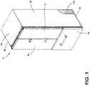
FIG. 1 is a front top perspective view of an appliance of the present disclosure; -
FIG. 2 is a rear top perspective view of a cabinet of an appliance of the present disclosure; -
FIG. 3 is an enlarged partial perspective view of a machine compartment of the present disclosure with a fascia; -
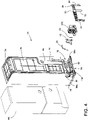
FIG. 4 is an exploded rear perspective view of an appliance with a machine compartment of the present disclosure with a fascia and a divider wall; -
FIG. 5 is a partial enlarged rear perspective view of a machine compartment of the present disclosure -
FIG. 6 is a side perspective view of a divider wall of the present disclosure operably coupled to a fan; -
FIG. 7 is an exploded view of the divider wall and the fan ofFIG. 6 ; -
FIG. 8 is a side elevational view of a fascia of the present disclosure with a central flange; -
FIG. 9 is a partial side elevational view of a machine compartment with a fascia of the present disclosure; and -
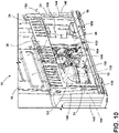
FIG. 10 is a partial side perspective view of a machine compartment of the present disclosure with an airflow path illustrated in solid lines. - The components in the figures are not necessarily to scale, emphasis instead being placed upon illustrating the principles described herein.
- The present illustrated embodiments reside primarily in combinations of method steps and apparatus components related to a fascia and divider wall for a machine compartment. Accordingly, the apparatus components and method steps have been represented, where appropriate, by conventional symbols in the drawings, showing only those specific details that are pertinent to understanding the embodiments of the present disclosure so as not to obscure the disclosure with details that will be readily apparent to those of ordinary skill in the art having the benefit of the description herein. Further, like numerals in the description and drawings represent like elements.
- For purposes of description herein, the terms "upper," "lower," "right," "left," "rear," "front," "vertical," "horizontal," and derivatives thereof shall relate to the disclosure as oriented in
FIG. 1 . Unless stated otherwise, the term "front" shall refer to the surface of the element closer to an intended viewer, and the term "rear" shall refer to the surface of the element further from the intended viewer. However, it is to be understood that the disclosure may assume various alternative orientations, except where expressly specified to the contrary. It is also to be understood that the specific devices and processes illustrated in the attached drawings, and described in the following specification are simply exemplary embodiments of the inventive concepts defined in the appended claims. Hence, specific dimensions and other physical characteristics relating to the embodiments disclosed herein are not to be considered as limiting, unless the claims expressly state otherwise. - The terms "including," "comprises," "comprising," or any other variation thereof, are intended to cover a non-exclusive inclusion, such that a process, method, article, or apparatus that comprises a list of elements does not include only those elements but may include other elements not expressly listed or inherent to such process, method, article, or apparatus. An element proceeded by "comprises a . . . " does not, without more constraints, preclude the existence of additional identical elements in the process, method, article, or apparatus that comprises the element.
- Referring to
FIGS. 1-10 ,reference numeral 10 generally designates an appliance that includes abase 12 and awrapper 14 operably coupled to thebase 12. Amachine compartment 16 is defined by thebase 12 and thewrapper 14, and adivider wall 18 is disposed within themachine compartment 16. Thedivider wall 18 includes awall body 20 and agasket 22 that is operably coupled to thewrapper 14. Thedivider wall 18 defines awarm air zone 24 and acool air zone 26 of themachine compartment 16. Afascia 28 is operably coupled to thewrapper 14 proximate to themachine compartment 16. Thefascia 28 includes anupper portion 30 that defines a plurality ofslots 32. Afirst side flange 34 is operably coupled to theupper portion 30, and asecond side flange 36 is operably coupled to an opposing end of theupper portion 30. Acentral flange 38 is disposed between the first andsecond side flanges base 12. - Referring to
FIGS. 1-4 , theappliance 10 is illustrated as a refrigerating appliance, but it is also contemplated that thefascia 28 described herein may be used with a variety of appliances. Theappliance 10 illustrated is a built-in appliance, such that arear wall 50 andsidewalls 52 of thewrapper 14 may be generally exposed. It is generally contemplated that therear wall 50 may be operably coupled to thebase 12, described further below. Theappliance 10 includes first andsecond doors body 58 of theappliance 10. As described herein, theterm body 58 may include similar features as thewrapper 14. For example, it is generally contemplated that thebody 58 may be formed from a metallic material, a plastic material, or other materials typically used to form acabinet 60 of theappliance 10. - The
cabinet 60 is generally formed from thewrapper 14 and aliner 62 to which thewrapper 14 is coupled. Thecabinet 60 is typically defined as aninsulated structure 64 by theliner 62 and thewrapper 14. It is generally contemplated that thewrapper 14 and theliner 62 may be formed from metals, polymers, metal alloys, combinations thereof, and other substantially rigid materials that can be used for vacuum insulated structures within appliances. Theliner 62 and thewrapper 14 are typically coupled to atrim breaker 66 to form theinsulated structure 64. Theliner 62 and thewrapper 14 also define an insulatingcavity 68 therebetween in which one ormore insulation materials 70 may be disposed. It is generally contemplated that theinsulation materials 70 may be a glass-type material, a carbon-based powder, silicone oxide-based materials, insulating gases, and otherstandard insulation materials 70 known in the art. Theinsulation materials 70 substantially fill the insulatingcavity 68 to form a substantially continuous layer between theliner 62 and thewrapper 14. The insulatingcavity 68 is evacuated by a vacuum to further define theinsulated structure 64 as a vacuum insulated structure. - With further reference to
FIGS. 1-4 , holes 72 are defined by thewrapper 14 and theliner 62 to provide a passage for electrical wiring and other typical appliance lines. For purposes of this disclosure, thewrapper 14 is described in detail; however, theliner 62 can be similarly constructed insofar as theliner 62 and thewrapper 14 generally have a similar shape to form theinsulated structure 64. Thewrapper 14 has top andbottom surfaces planar surface 78, and acurved surface 80 as well as thesidewalls 52 mentioned above. Thebottom surface 76 of thewrapper 14 is operably coupled to thebase 12. Thecurved surface 80 of thewrapper 14 and the base 12 at least partially define themachine compartment 16. Stated differently,machine components 82 can be positioned on thebase 12 within themachine compartment 16 beneath the rearplanar surface 78 and proximate to thecurved surface 80 of thewrapper 14. - The
wrapper 14 is positioned on and coupled to thebase 12, which structurally supports theappliance 10. The base 12 may be formed from metal, plastic, or other materials known to provide structural, base support for theappliance 10. The base 12 may be a single piece of material extending across thebottom surface 76 of thewrapper 14. Additionally or alternatively, thebase 12 may include base rails 90 positioned proximate to thesidewalls 52 of theappliance cabinet 60 and coupled to thebottom surface 76 of thewrapper 14. In either construction, the base 12 at least partially extends beyond thecurved surface 80 of thewrapper 14 to lie substantially perpendicular with the rearplanar surface 78 of thewrapper 14. - Referring now to
FIGS. 4-7 , the base rails 90 include afirst rail 90a and asecond rail 90b, which may be collectively referred to as the base rails 90. Asupport plate 92 configured to support themachine components 82 within themachine compartment 16 can be positioned over and coupled to the base rails 90 to define agap 94 therebetween. Thegap 94 may provide passage for the electrical wiring and/or appliance lines 96. For example, when theappliance 10 is a refrigerator and/or freezer,appliance lines 96 configured to direct water are connected to theappliance 10 and may pass through thegap 94 defined by the base rails 90 and thesupport plate 92. - As mentioned above, the
machine compartment 16 includes thedivider wall 18 in addition to themachine components 82. Themachine components 82 of themachine compartment 16 include, but are not limited to acompressor 100, afan 102, and acondenser 104. Thefan 102 is generally disposed between thecompressor 100 and thecondenser 104, and thefan 102 is operably coupled to thecondenser 104 to direct anairflow 106 from acondenser side 108 of themachine compartment 16 to acompressor side 110 of themachine compartment 16. It is generally contemplated that thedivider wall 18 separates thecondenser side 108 and thecompressor side 110 of themachine compartment 16 to define thecool air zone 26 and thewarm air zone 24, respectively. Thedivider wall 18 minimizes recirculation of theairflow 106 between thewarm air zone 24 and thecool air zone 26, as described below. - The
compressor 100 operates to compress a thermal exchange media, which is ultimately cooled and condensed by thecondenser 104. This thermal regulation process is described in further detail below. Thecompressor 100 generates and releases energy in the form of heat during operation, which ultimately defines thewarm air zone 24 of themachine compartment 16. Thecondenser 104 releases a cool draft into themachine compartment 16 to define thecool air zone 26. Thecondenser 104 remains separated from thecompressor 100 via thedivider wall 18 to minimize the heat from thecompressor 100 impacting the operation of thecondenser 104. - For example, in conventional machine compartments the condenser may be exposed to the heat radiating from the compressor. The more heat that the condenser is exposed to, the less efficient the condenser may be at cooling the system. This inefficiency in a conventional system may lead to the compressor ultimately working more to compensate for the heated condenser. Thus, it is advantageous separate and segregate the compressor and the condenser to maintain an efficient system.
- With further reference to
FIGS. 4-7 , thedivider wall 18 is disposed around thefan 102 and is operably coupled to thefan 102. As mentioned above, thedivider wall 18 includes thewall body 20 and thegasket 22. Thegasket 22 is generally disposed around anouter edge 112 of thewall body 20 and is operably coupled to thecurved surface 80 of thewrapper 14. Thegasket 22 may be formed from a generally compressive material and is generally configured to absorb movement or other engagement between thewrapper 14 and thedivider wall 18. It is also contemplated that thegasket 22 can include afirst gasket 114 and asecond gasket 116. Thefirst gasket 114 extends along thewall body 20 proximate to thecurved surface 80 of thewrapper 14, and thesecond gasket 116 extends along a side of thefan 102 proximate to thecentral flange 38. For example, thesecond gasket 116 extends along a side of thefan 102 between thefan 102 and thecentral flange 38. In such configuration, thesecond gasket 116 generally minimizes contact between thecentral flange 38 of thefascia 28, and thefirst gasket 114 minimizes contact between thewall body 20 and thewrapper 14. - The
wall body 20 extends around anouter wall 118 of thefan 102 to define a barrier between thewarm air zone 24 and thecool air zone 26. It is generally contemplated that thewall body 20 can be formed from a metal, a plastic, or any other generally rigid material that resists airflow penetration. A portion of thewall body 20 may extend into thecool air zone 26 and is coupled to theouter wall 118 of thefan 102. Thefan 102 includes retention clips 120 that couple thewall body 20 to thefan 102. Additionally or alternatively, theouter wall 118 of thefan 102 may include a peripheral flange that can define a groove in which thewall body 20 can be disposed. It is also contemplated that thewall body 20 may be welded, fastened, or otherwise coupled to thefan 102. In any one of these configurations, the addition of thewall body 20 minimizes the mixing of theairflow 106 between thewarm air zone 24 and thecool air zone 26 of themachine compartment 16. - With further reference to
FIGS. 4-7 , theouter wall 118 of thefan 102 defines aspace 122 in which thecondenser 104 is positioned. Thewall body 20 of thedivider wall 18 may be positioned proximate to thecondenser 104 within thecool air zone 26 to further minimize mixing of thewarm air zone 24 and thecool air zone 26. Thecondenser 104 and thefan 102 may be operably coupled to acontainer 124, which is operably coupled to thesupport plate 92 of thebase 12. Thecontainer 124 also includes retention clips 126 similar to the retention clips 120 of thefan 102, and thewall body 20 is also operably coupled to the retention clips 126 of thecontainer 124. It is also contemplated that the wall body may be spot welded, welded, or coupled to thefan 102 and thecontainer 124 by coupling methods other than the retention clips 120, 126. - An
extension wall 128 of thewall body 20 extends along a side of thecondenser 104 and is coupled to one of the retention clips 120 of thefan 102. Theextension wall 128 includes acurved end 130 that extends beneath thecondenser 104. It is generally contemplated that theextension wall 128, in particular thecurved end 130, helps to channel the cool draft from thecondenser 104 within thecool air zone 26. Theextension wall 128 also forms a barrier between any potential warm air from thewarm air zone 24 and thecondenser 104. As will be described further below, thefan 102 is configured to direct theairflow 106 away from thecondenser 104 and toward thecompressor 100, which both minimizes the mixing of warm air from thewarm air zone 24 with thecool air zone 26 and at least partially cools thecompressor 100 to maintain the overall efficiency of the system. - Referring now to
FIGS. 8-10 and as mentioned above, thefascia 28 includes theupper portion 30 that defines the plurality ofslots 32 along a length L1 of theupper portion 30. Thefirst side flange 34 and thecentral flange 38 cooperate to define afirst aperture 140 of thefascia 28, and thesecond side flange 36 and thecentral flange 38 cooperate to define asecond aperture 142 of thefascia 28. As illustrated inFIG. 8 , the plurality ofslots 32 are defined above thefirst aperture 140 and above thesecond aperture 142, such that theupper portion 30 remains solid proximate to thecentral flange 38, described further below. The first andsecond apertures machine compartment 16. Thewarm air zone 24 is partially defined by thefirst side flange 34 and thecentral flange 38. Thecool air zone 26 is partially defined by thesecond side flange 36 and thecentral flange 38. The first andsecond side flanges slit 144 along a length L2 of each of the first andsecond side flanges - It is generally contemplated that the
slit 144 defined by thefirst side flange 34 is configured to direct theairflow 106 within themachine compartment 16 from inside themachine compartment 16 to an area exterior to themachine compartment 16. It is also contemplated that the plurality ofslots 32 defined along theupper portion 30 of thefascia 28 are configured to direct theairflow 106 into and out of themachine compartment 16 to at least partially regulate thewarm air zone 24 and thecool air zone 26. By way of example, not limitation, theairflow 106 may be directed into theslots 32 proximate to thecool air zone 26 and directed out of theslots 32 proximate to thewarm air zone 24. Additionally or alternatively, theairflow 106 may be directed out of all of the plurality ofslots 32 defined by theupper portion 30 of thefascia 28 to regulate thewarm air zone 24 and thecool air zone 26. - With further reference to
FIGS. 8-10 , the first andsecond side flanges attachment portion 146 proximate to theslits 144. Theattachment portion 146 is configured to couple thefascia 28 to aside panel 148 of theappliance 10. Theside panel 148 is coupled to thebase 12, and theattachment portion 146 is coupled to aflange 150 of theside panel 148. It is also contemplated that each of the first andsecond side flanges central flange 38 are coupled to thebase 12 via coupling features 152, such as screws. The coupling features 152 may also include, but are not limited to, rivets, nuts and bolts, and other coupling features 152 generally known in the art. It is also contemplated that thefascia 28 may be coupled to thewrapper 14 via spot welding or other attachment methods. For example, thefascia 28 also includes at least oneextension 154 that upwardly extends from theupper portion 30 of thefascia 28 and is configured to operably couple thefascia 28 to thewrapper 14. - The
fascia 28 may be configured, as described above, with the first andsecond side flanges central flange 38. In such a configuration, thefascia 28 defines the first andsecond apertures machine compartment 16. In an alternate configuration, thefascia 28 defines asingle aperture 140a, such that thefascia 28 is free from thecentral flange 38. This alternate configuration of thefascia 28 may provide maximized access to themachine compartment 16. It is generally contemplated that, in either configuration, theupper portion 30 of thefascia 28 concealsappliance lines 96 that extend toward themachine compartment 16 while maximizing theairflow 106 into and out of themachine compartment 16. - With further reference to
FIGS. 8-10 , thecompressor 100 is operably coupled to thecondenser 104, which condenses a thermal exchange media from a gaseous state into a liquid state. This, at least partially, defines the cooling effect of the refrigeration system. As mentioned above, thecool air zone 26 is defined as thecondenser side 108 of themachine compartment 16 as thecondenser 104 is configured to cool the thermal exchange media in the gaseous state from thecompressor 100 into the liquid state. Thecondenser 104 typically releases a cool draft as compared to thecompressor 100. The cooled thermal exchange media is utilized to cool theappliance 10. Thecompressor 100 and thecondenser 104 are separated from one another by thedivider wall 18 in order to maximize the efficiency of the refrigeration system, as mentioned above. Thedivider wall 18 blocks the heat released by thecompressor 100 from acting upon thecondenser 104. - In addition, the
fan 102 is configured to direct theairflow 106 from thecondenser side 108 to thecompressor side 110. Thefan 102 maintains thecool air zone 26 by redirecting theairflow 106, which maximizes the overall efficiency of the refrigeration system. The combination of thefan 102 and thedivider wall 18 maximizes the efficiency of at least thecompressor 100 by keeping warm air within thewarm air zone 24 separate from thecondenser 104 in thecool air zone 26. Thedivider wall 18 is disposed around thefan 102 to at least partially seal off thewarm air zone 24 of themachine compartment 16 from thecool air zone 26. As mentioned above, thefan 102 is directed toward thewarm air zone 24 of themachine compartment 16 to prevent awarm airflow path 156 that may radiate from thecompressor 100. Instead, thewarm airflow path 156 may be expelled from thewarm air zone 24 through thefirst aperture 140, theslit 144 defined by thefirst side flange 34, and the plurality ofslots 32 defined by thefascia 28. - The suction generated by the
fan 102 maintains thecool air zone 26 and minimizes potential penetration of thewarm airflow path 156 from thewarm air zone 24. Thesecond aperture 142 is illustrated as being smaller than thefirst aperture 140, such that more of acool airflow 158 within thecool air zone 26 is retained and can be directed toward thewarm air zone 24. The maintenance of thecool air zone 26 minimizes the work of thecompressor 100 to operate the refrigeration system. Moreover, the cooling of thewarm air zone 24 with thecool airflow 158 via thefan 102 helps to maintain the overall regulation and operation of thecompressor 100 within thewarm air zone 24. - Referring again to
FIGS. 1-10 , thedivider wall 18 and thefascia 28 help to regulate the refrigeration system. Specifically, thedivider wall 18 minimizes potential mixing between thewarm air zone 24 and thecool air zone 26, which maximizes the efficiency of the refrigeration system. Retaining the warm air within thewarm air zone 24 minimizes the likelihood that thecompressor 100 will work harder to cool thecondenser 104 to maintain the temperature of the overall system. Further, thefascia 28 advantageously provides an outlet for theairflow 106 while covering theappliance lines 96 that may otherwise be exposed. Thus, thefascia 28 provides coverage of theappliance lines 96 to minimize the user contacting theappliance lines 96 while allowing theairflow 106 to efficiently circulate within, into, and out of themachine compartment 16. - The invention disclosed herein is further summarized in the following paragraphs and is further characterized by combinations of any and all of the various aspects described therein.
- According to one aspect of the present disclosure, an appliance includes a base. A wrapper is operably coupled to the base. A machine compartment is defined by the base and the wrapper. A divider wall is disposed within the machine compartment. The divider wall includes a wall body and a gasket that is operably coupled to the wrapper and defines a warm air zone and a cool air zone of the machine compartment. A fascia is operably coupled to the wrapper that is proximate to the machine compartment. The fascia includes an upper portion that defines a plurality of slots, a first side flange that is operably coupled to the upper portion, a second side flange that is operably coupled to an opposing end of the upper portion, and a central flange that is disposed between the first and second side flanges and operably coupled to the base.
- According to another aspect, a first side flange and a central flange cooperate to define a first aperture, and a second side flange and the central flange cooperate to define a second aperture. The first and second apertures provide access to a machine compartment.
- According to another aspect, a warm air zone is partially defined by a first side flange and a central flange. A cool air zone is partially defined by a second side flange and the central flange.
- According to another aspect, a fan is disposed within a machine compartment that is proximate to a divider wall. The divider wall is coupled to and surrounds the fan to separate a warm air zone and a cool air zone.
- According to another aspect, first and second side flanges each define a slit that is configured to direct an airflow path exterior to a machine compartment and within the machine compartment.
- According to another aspect, a plurality of slots are defined along an upper portion of a fascia to direct an airflow path into and out of a machine compartment to at least partially regulate a warm air zone and a cool air zone.
- According to another aspect, a gasket of a divider wall is operably coupled to a wrapper and a central flange around a wall body.
- According to another aspect of the present disclosure, a cabinet for an appliance includes a base. A rear wall is operably coupled to the base. A machine compartment is defined between the rear wall and the base. A fascia is operably coupled to the rear wall and is proximate to the machine compartment. The fascia includes first and second side flanges and an upper portion that cooperate to define at least one aperture. A divider wall is disposed within the machine compartment and is operably coupled to the rear wall.
- According to another aspect, a divider wall includes a wall body and a gasket that are operably coupled to a rear wall and a fascia.
- According to another aspect, a fascia includes a central flange. At least one aperture includes a first aperture and a second aperture.
- According to another aspect, a first side flange and a central flange cooperate to define a first aperture. A second side flange and the central flange cooperate to define a second aperture.
- According to another aspect, a divider wall defines a warm air zone and a cool air zone within a machine compartment. The divider wall minimizes recirculation of airflow between the warm air zone and the cool air zone.
- According to another aspect, an upper portion of a fascia define a plurality of slots along a length of the upper portion. A plurality of slots are configured to maintain a warm air zone and a cool air zone.
- According to another aspect, a cabinet further includes a fan that is disposed within a machine compartment and is operably coupled to a base. A divider wall is disposed around the fan to define a warm air zone and a cool air zone of the machine compartment.
- According to yet another aspect of the present disclosure, a machine compartment assembly for an appliance cabinet includes a fascia that is configured to engage said appliance cabinet. The fascia includes an upper portion that defines a plurality of slots along a length of the upper portion. The fascia also includes a first side flange that is operably coupled to the upper portion and a second side flange that is operably coupled to the upper portion. The first side flange and the second side flange each define a slit. A divider wall is proximate to the fascia. The divider wall includes a wall body that has an outer edge and defines a warm air zone and a cool air zone. The divider wall also includes a gasket is operably coupled to the outer edge of the wall body.
- According to another aspect, a fascia directs an airflow path relative to regulate a warm air zone and a cool air zone of a machine compartment.
- According to another aspect, an airflow path is directed via a plurality of slots.
- According to another aspect, the machine compartment assembly further includes a fan that is operably coupled to a divider wall and further defines a warm air zone and a cool air zone.
- According to another aspect, a fascia includes a central flange that is operably coupled to a divider wall.
- According to another aspect, a divider wall includes a gasket that is operably coupled to a central flange.
Claims (15)
- A refrigerator appliance (10) comprising a cabinet (60), said cabinet (60) comprising:a base (12);a wrapper (14) operably coupled to the base (12); anda machine compartment (16) defined between the wrapper (14) and the base (12),wherein:a fascia (28) is operably coupled to the wrapper (14) proximate to the machine compartment (16), the fascia (28) including first and second side flanges (34, 36) and an upper portion (30) that cooperate to define at least one aperture (140, 142);and wherein:a divider wall (18) is disposed within the machine compartment (16) and operably coupled to the wrapper (14), the divider wall (18) including a wall body (20);a gasket (22) is disposed around the wall body (20) of the divider wall (18); anda fan (102) is disposed within the machine compartment (16) proximate the divider wall (18), the fan (102) including retention clips (120) that couple the wall body (20) of the divider wall (18) to the fan (102).
- The refrigerator appliance (10) of claim 1, wherein the fascia (28) includes a central flange (38).
- The refrigerator appliance (10) of either of claims 1 and 2, wherein the at least one aperture (140, 142) includes a first aperture (140) and a second aperture (142).
- The refrigerator appliance (10) of claim 3, wherein the first and second apertures (140, 142) provide access to the machine compartment (16).
- The refrigerator appliance (10) of any one of claims 2-4, wherein the gasket (22) includes a first gasket (114) extending along the wall body (20) and a second gasket (116) operably coupled to the central flange (38).
- The refrigerator appliance (10) of any one of claims 3-5, wherein the first side flange (34) and the central flange (38) cooperate to define the first aperture (140), and wherein the second side flange (36) and the central flange (38) cooperate to define the second aperture (142).
- The refrigerator appliance (10) of any one of claims 2-6, wherein the divider wall (18) defines a warm air zone (24) and a cool air zone (26) within the machine compartment (16), and wherein the divider wall (18) minimizes recirculation of airflow (106) between the warm air zone (24) and the cool air zone (26).
- The refrigerator appliance (10) of claim 7, wherein the warm air zone (24) is partially defined by the first side flange (34) and the central flange (38).
- The refrigerator appliance (10) of claim 8, wherein the cool air zone (26) is partially defined by the second side flange (36) and the central flange (38).
- The refrigerator appliance (10) of any one of claims 7-9, wherein an upper portion (30) of the fascia (28) defines a plurality of slots (32) along a length of the upper portion (30), and wherein the plurality of slots (32) are configured to maintain the warm air zone (24) and the cool air zone (26).
- The refrigerator appliance (10) of any one of claims 7-10, wherein the fascia (28) directs an airflow path (156) to regulate the warm air zone (24) and the cool air zone (26) of the machine compartment (16).
- The refrigerator appliance (10) of claim 11, wherein the plurality of slots (32) defined along the upper portion (30) of the fascia (28) direct the airflow path (156) into and out of the machine compartment (16) to at least partially regulate the warm air zone (24) and the cool air zone (26).
- The refrigerator appliance (10) of either of claims 11 and 12, wherein the first and second side flanges (34, 36) each define a slit (144) configured to direct the airflow path (156) exterior to the machine compartment (16) and within the machine compartment (16).
- The refrigerator appliance (10) of any one of claims 1-13, further comprising:
a container (124) including retention clips (126), wherein the fan (102) is operably coupled to the container (124) via the retention clips (126). - The refrigerator appliance (10) of any one of claims 7-14, wherein the divider wall (18) is coupled to and surrounds the fan (102) to separate the warm air zone (24) and the cool air zone (26).
Applications Claiming Priority (1)
| Application Number | Priority Date | Filing Date | Title |
|---|---|---|---|
| US17/139,091 US11719486B2 (en) | 2020-12-31 | 2020-12-31 | Fascia and divider wall for a machine compartment |
Publications (1)
| Publication Number | Publication Date |
|---|---|
| EP4023973A1 true EP4023973A1 (en) | 2022-07-06 |
Family
ID=79021893
Family Applications (1)
| Application Number | Title | Priority Date | Filing Date |
|---|---|---|---|
| EP21217205.0A Pending EP4023973A1 (en) | 2020-12-31 | 2021-12-22 | Fascia and divider wall for a machine compartment |
Country Status (3)
| Country | Link |
|---|---|
| US (1) | US11719486B2 (en) |
| EP (1) | EP4023973A1 (en) |
| CN (1) | CN114688791A (en) |
Cited By (1)
| Publication number | Priority date | Publication date | Assignee | Title |
|---|---|---|---|---|
| EP4563922A1 (en) * | 2023-11-30 | 2025-06-04 | Whirlpool Corporation | Refrigerator with a vacuum-insulated structure supported by a structural support with a baseplate welded to the vacuum-insulated structure |
Families Citing this family (3)
| Publication number | Priority date | Publication date | Assignee | Title |
|---|---|---|---|---|
| DE102022202214A1 (en) * | 2022-03-04 | 2023-09-07 | BSH Hausgeräte GmbH | Refrigeration device, heat exchanger assembly for a refrigeration device, method for installing a fan in a housing and method for manufacturing a heat exchanger assembly |
| KR20240001590A (en) * | 2022-06-27 | 2024-01-03 | 엘지전자 주식회사 | Refrigerator |
| DE102022213434B3 (en) | 2022-12-12 | 2024-03-28 | BSH Hausgeräte GmbH | Refrigeration device |
Citations (4)
| Publication number | Priority date | Publication date | Assignee | Title |
|---|---|---|---|---|
| KR20070102190A (en) * | 2006-04-14 | 2007-10-18 | 주식회사 대우일렉트로닉스 | Refrigerator heatsink |
| US20160116204A1 (en) * | 2014-10-22 | 2016-04-28 | General Electric Company | Fan with integrated plenum |
| EP3647695A1 (en) * | 2018-11-01 | 2020-05-06 | LG Electronics Inc. | Refrigerator |
| WO2020173359A1 (en) * | 2019-02-26 | 2020-09-03 | 青岛海尔电冰箱有限公司 | Refrigerator with partition |
Family Cites Families (14)
| Publication number | Priority date | Publication date | Assignee | Title |
|---|---|---|---|---|
| KR20000033333A (en) | 1998-11-23 | 2000-06-15 | 구자홍 | Fixed structure of fan guide of machinery room in refrigerator |
| KR100675685B1 (en) | 2000-01-11 | 2007-02-01 | 주식회사 엘지이아이 | Machine room cover coupling structure of the refrigerator |
| KR100557099B1 (en) | 2003-12-09 | 2006-03-03 | 엘지전자 주식회사 | Heat Sink of Built-in Refrigerator |
| EP1559975A3 (en) | 2004-01-28 | 2006-04-19 | Lg Electronics Inc. | Refrigerator having cross flow fan |
| KR20060081806A (en) * | 2005-01-10 | 2006-07-13 | 삼성전자주식회사 | Refrigerator |
| KR100759047B1 (en) * | 2006-07-03 | 2007-09-14 | 주식회사 대우일렉트로닉스 | Heat dissipation and defrost water evaporation system in refrigerator machine room and control method |
| KR20090032733A (en) | 2007-09-28 | 2009-04-01 | 엘지전자 주식회사 | Radiator of refrigerator |
| WO2009141129A1 (en) * | 2008-05-23 | 2009-11-26 | Aktiebolaget Electrolux | Cold appliance |
| CN203454548U (en) * | 2013-08-13 | 2014-02-26 | 浙江海利士电器有限公司 | Refrigerator sealing plate |
| KR102168586B1 (en) | 2013-11-29 | 2020-10-22 | 삼성전자주식회사 | Refrigerator |
| KR102257475B1 (en) * | 2014-09-05 | 2021-05-31 | 삼성전자주식회사 | Refrigerator |
| JP2020070953A (en) | 2018-10-30 | 2020-05-07 | 日本電産株式会社 | Cooling system |
| CN109539656B (en) * | 2018-11-12 | 2021-02-26 | 合肥美的电冰箱有限公司 | Refrigerator with a door |
| CN111609615A (en) | 2019-02-26 | 2020-09-01 | 青岛海尔电冰箱有限公司 | Large volume refrigerator |
-
2020
- 2020-12-31 US US17/139,091 patent/US11719486B2/en active Active
-
2021
- 2021-12-22 EP EP21217205.0A patent/EP4023973A1/en active Pending
- 2021-12-31 CN CN202111667678.1A patent/CN114688791A/en active Pending
Patent Citations (4)
| Publication number | Priority date | Publication date | Assignee | Title |
|---|---|---|---|---|
| KR20070102190A (en) * | 2006-04-14 | 2007-10-18 | 주식회사 대우일렉트로닉스 | Refrigerator heatsink |
| US20160116204A1 (en) * | 2014-10-22 | 2016-04-28 | General Electric Company | Fan with integrated plenum |
| EP3647695A1 (en) * | 2018-11-01 | 2020-05-06 | LG Electronics Inc. | Refrigerator |
| WO2020173359A1 (en) * | 2019-02-26 | 2020-09-03 | 青岛海尔电冰箱有限公司 | Refrigerator with partition |
Cited By (1)
| Publication number | Priority date | Publication date | Assignee | Title |
|---|---|---|---|---|
| EP4563922A1 (en) * | 2023-11-30 | 2025-06-04 | Whirlpool Corporation | Refrigerator with a vacuum-insulated structure supported by a structural support with a baseplate welded to the vacuum-insulated structure |
Also Published As
| Publication number | Publication date |
|---|---|
| US11719486B2 (en) | 2023-08-08 |
| CN114688791A (en) | 2022-07-01 |
| US20220205705A1 (en) | 2022-06-30 |
Similar Documents
| Publication | Publication Date | Title |
|---|---|---|
| US11719486B2 (en) | Fascia and divider wall for a machine compartment | |
| EP3647695A1 (en) | Refrigerator | |
| EP3845840B1 (en) | Side access panel for an appliance | |
| US8079231B2 (en) | Housing for a refrigerator | |
| US20220042736A1 (en) | Refrigerated compartment air distribution assembly | |
| JP3408101B2 (en) | refrigerator | |
| JP2006138609A (en) | refrigerator | |
| JP2001174125A (en) | refrigerator | |
| US7216493B2 (en) | Refrigerator methods and apparatus | |
| JP2021173448A (en) | refrigerator | |
| JPH10205995A (en) | Refrigerator | |
| JPH10205989A (en) | Refrigerator | |
| EP3943844B1 (en) | Refrigerator | |
| JP2023070202A (en) | refrigerator | |
| JP2005180720A (en) | refrigerator | |
| CN115218586A (en) | Heat insulation box and heat insulation door | |
| JP4141428B2 (en) | Cooling storage | |
| JP2012002483A (en) | Refrigerator-freezer | |
| JPH1144478A (en) | refrigerator | |
| CN221992166U (en) | Refrigerator with a refrigerator body | |
| CN221924126U (en) | refrigerator | |
| JP5922541B2 (en) | Refrigerator | |
| JP7764022B2 (en) | refrigerator | |
| JP2011080693A (en) | Refrigerator | |
| KR100441011B1 (en) | Refregerator |
Legal Events
| Date | Code | Title | Description |
|---|---|---|---|
| PUAI | Public reference made under article 153(3) epc to a published international application that has entered the european phase |
Free format text: ORIGINAL CODE: 0009012 |
|
| STAA | Information on the status of an ep patent application or granted ep patent |
Free format text: STATUS: THE APPLICATION HAS BEEN PUBLISHED |
|
| AK | Designated contracting states |
Kind code of ref document: A1 Designated state(s): AL AT BE BG CH CY CZ DE DK EE ES FI FR GB GR HR HU IE IS IT LI LT LU LV MC MK MT NL NO PL PT RO RS SE SI SK SM TR |
|
| STAA | Information on the status of an ep patent application or granted ep patent |
Free format text: STATUS: REQUEST FOR EXAMINATION WAS MADE |
|
| 17P | Request for examination filed |
Effective date: 20230104 |
|
| RBV | Designated contracting states (corrected) |
Designated state(s): AL AT BE BG CH CY CZ DE DK EE ES FI FR GB GR HR HU IE IS IT LI LT LU LV MC MK MT NL NO PL PT RO RS SE SI SK SM TR |
|
| RAP3 | Party data changed (applicant data changed or rights of an application transferred) |
Owner name: WHIRLPOOL CORPORATION |
|
| STAA | Information on the status of an ep patent application or granted ep patent |
Free format text: STATUS: EXAMINATION IS IN PROGRESS |
|
| 17Q | First examination report despatched |
Effective date: 20240513 |
|
| P01 | Opt-out of the competence of the unified patent court (upc) registered |
Free format text: CASE NUMBER: APP_49085/2024 Effective date: 20240828 |