EP4023928B1 - Verfahren zur minimierung des leistungsbedarfs für eine wasserstofftankstelle - Google Patents
Verfahren zur minimierung des leistungsbedarfs für eine wasserstofftankstelle Download PDFInfo
- Publication number
- EP4023928B1 EP4023928B1 EP21156634.4A EP21156634A EP4023928B1 EP 4023928 B1 EP4023928 B1 EP 4023928B1 EP 21156634 A EP21156634 A EP 21156634A EP 4023928 B1 EP4023928 B1 EP 4023928B1
- Authority
- EP
- European Patent Office
- Prior art keywords
- pressure
- fill
- station
- pump
- power demand
- Prior art date
- Legal status (The legal status is an assumption and is not a legal conclusion. Google has not performed a legal analysis and makes no representation as to the accuracy of the status listed.)
- Active
Links
Images


Classifications
-
- F—MECHANICAL ENGINEERING; LIGHTING; HEATING; WEAPONS; BLASTING
- F17—STORING OR DISTRIBUTING GASES OR LIQUIDS
- F17C—VESSELS FOR CONTAINING OR STORING COMPRESSED, LIQUEFIED OR SOLIDIFIED GASES; FIXED-CAPACITY GAS-HOLDERS; FILLING VESSELS WITH, OR DISCHARGING FROM VESSELS, COMPRESSED, LIQUEFIED, OR SOLIDIFIED GASES
- F17C5/00—Methods or apparatus for filling containers with liquefied, solidified, or compressed gases under pressures
- F17C5/02—Methods or apparatus for filling containers with liquefied, solidified, or compressed gases under pressures for filling with liquefied gases
- F17C5/04—Methods or apparatus for filling containers with liquefied, solidified, or compressed gases under pressures for filling with liquefied gases requiring the use of refrigeration, e.g. filling with helium or hydrogen
-
- F—MECHANICAL ENGINEERING; LIGHTING; HEATING; WEAPONS; BLASTING
- F17—STORING OR DISTRIBUTING GASES OR LIQUIDS
- F17C—VESSELS FOR CONTAINING OR STORING COMPRESSED, LIQUEFIED OR SOLIDIFIED GASES; FIXED-CAPACITY GAS-HOLDERS; FILLING VESSELS WITH, OR DISCHARGING FROM VESSELS, COMPRESSED, LIQUEFIED, OR SOLIDIFIED GASES
- F17C5/00—Methods or apparatus for filling containers with liquefied, solidified, or compressed gases under pressures
- F17C5/002—Automated filling apparatus
- F17C5/007—Automated filling apparatus for individual gas tanks or containers, e.g. in vehicles
-
- F—MECHANICAL ENGINEERING; LIGHTING; HEATING; WEAPONS; BLASTING
- F17—STORING OR DISTRIBUTING GASES OR LIQUIDS
- F17C—VESSELS FOR CONTAINING OR STORING COMPRESSED, LIQUEFIED OR SOLIDIFIED GASES; FIXED-CAPACITY GAS-HOLDERS; FILLING VESSELS WITH, OR DISCHARGING FROM VESSELS, COMPRESSED, LIQUEFIED, OR SOLIDIFIED GASES
- F17C13/00—Details of vessels or of the filling or discharging of vessels
-
- F—MECHANICAL ENGINEERING; LIGHTING; HEATING; WEAPONS; BLASTING
- F17—STORING OR DISTRIBUTING GASES OR LIQUIDS
- F17C—VESSELS FOR CONTAINING OR STORING COMPRESSED, LIQUEFIED OR SOLIDIFIED GASES; FIXED-CAPACITY GAS-HOLDERS; FILLING VESSELS WITH, OR DISCHARGING FROM VESSELS, COMPRESSED, LIQUEFIED, OR SOLIDIFIED GASES
- F17C5/00—Methods or apparatus for filling containers with liquefied, solidified, or compressed gases under pressures
- F17C5/06—Methods or apparatus for filling containers with liquefied, solidified, or compressed gases under pressures for filling with compressed gases
-
- F—MECHANICAL ENGINEERING; LIGHTING; HEATING; WEAPONS; BLASTING
- F17—STORING OR DISTRIBUTING GASES OR LIQUIDS
- F17C—VESSELS FOR CONTAINING OR STORING COMPRESSED, LIQUEFIED OR SOLIDIFIED GASES; FIXED-CAPACITY GAS-HOLDERS; FILLING VESSELS WITH, OR DISCHARGING FROM VESSELS, COMPRESSED, LIQUEFIED, OR SOLIDIFIED GASES
- F17C7/00—Methods or apparatus for discharging liquefied, solidified, or compressed gases from pressure vessels, not covered by another subclass
- F17C7/02—Discharging liquefied gases
- F17C7/04—Discharging liquefied gases with change of state, e.g. vaporisation
-
- F—MECHANICAL ENGINEERING; LIGHTING; HEATING; WEAPONS; BLASTING
- F17—STORING OR DISTRIBUTING GASES OR LIQUIDS
- F17C—VESSELS FOR CONTAINING OR STORING COMPRESSED, LIQUEFIED OR SOLIDIFIED GASES; FIXED-CAPACITY GAS-HOLDERS; FILLING VESSELS WITH, OR DISCHARGING FROM VESSELS, COMPRESSED, LIQUEFIED, OR SOLIDIFIED GASES
- F17C2203/00—Vessel construction, in particular walls or details thereof
- F17C2203/03—Thermal insulations
-
- F—MECHANICAL ENGINEERING; LIGHTING; HEATING; WEAPONS; BLASTING
- F17—STORING OR DISTRIBUTING GASES OR LIQUIDS
- F17C—VESSELS FOR CONTAINING OR STORING COMPRESSED, LIQUEFIED OR SOLIDIFIED GASES; FIXED-CAPACITY GAS-HOLDERS; FILLING VESSELS WITH, OR DISCHARGING FROM VESSELS, COMPRESSED, LIQUEFIED, OR SOLIDIFIED GASES
- F17C2221/00—Handled fluid, in particular type of fluid
- F17C2221/01—Pure fluids
- F17C2221/012—Hydrogen
-
- F—MECHANICAL ENGINEERING; LIGHTING; HEATING; WEAPONS; BLASTING
- F17—STORING OR DISTRIBUTING GASES OR LIQUIDS
- F17C—VESSELS FOR CONTAINING OR STORING COMPRESSED, LIQUEFIED OR SOLIDIFIED GASES; FIXED-CAPACITY GAS-HOLDERS; FILLING VESSELS WITH, OR DISCHARGING FROM VESSELS, COMPRESSED, LIQUEFIED, OR SOLIDIFIED GASES
- F17C2223/00—Handled fluid before transfer, i.e. state of fluid when stored in the vessel or before transfer from the vessel
- F17C2223/01—Handled fluid before transfer, i.e. state of fluid when stored in the vessel or before transfer from the vessel characterised by the phase
- F17C2223/0107—Single phase
- F17C2223/013—Single phase liquid
-
- F—MECHANICAL ENGINEERING; LIGHTING; HEATING; WEAPONS; BLASTING
- F17—STORING OR DISTRIBUTING GASES OR LIQUIDS
- F17C—VESSELS FOR CONTAINING OR STORING COMPRESSED, LIQUEFIED OR SOLIDIFIED GASES; FIXED-CAPACITY GAS-HOLDERS; FILLING VESSELS WITH, OR DISCHARGING FROM VESSELS, COMPRESSED, LIQUEFIED, OR SOLIDIFIED GASES
- F17C2223/00—Handled fluid before transfer, i.e. state of fluid when stored in the vessel or before transfer from the vessel
- F17C2223/01—Handled fluid before transfer, i.e. state of fluid when stored in the vessel or before transfer from the vessel characterised by the phase
- F17C2223/0146—Two-phase
- F17C2223/0153—Liquefied gas, e.g. LPG, GPL
- F17C2223/0161—Liquefied gas, e.g. LPG, GPL cryogenic, e.g. LNG, GNL, PLNG
-
- F—MECHANICAL ENGINEERING; LIGHTING; HEATING; WEAPONS; BLASTING
- F17—STORING OR DISTRIBUTING GASES OR LIQUIDS
- F17C—VESSELS FOR CONTAINING OR STORING COMPRESSED, LIQUEFIED OR SOLIDIFIED GASES; FIXED-CAPACITY GAS-HOLDERS; FILLING VESSELS WITH, OR DISCHARGING FROM VESSELS, COMPRESSED, LIQUEFIED, OR SOLIDIFIED GASES
- F17C2225/00—Handled fluid after transfer, i.e. state of fluid after transfer from the vessel
- F17C2225/01—Handled fluid after transfer, i.e. state of fluid after transfer from the vessel characterised by the phase
- F17C2225/0107—Single phase
- F17C2225/0123—Single phase gaseous, e.g. CNG, GNC
-
- F—MECHANICAL ENGINEERING; LIGHTING; HEATING; WEAPONS; BLASTING
- F17—STORING OR DISTRIBUTING GASES OR LIQUIDS
- F17C—VESSELS FOR CONTAINING OR STORING COMPRESSED, LIQUEFIED OR SOLIDIFIED GASES; FIXED-CAPACITY GAS-HOLDERS; FILLING VESSELS WITH, OR DISCHARGING FROM VESSELS, COMPRESSED, LIQUEFIED, OR SOLIDIFIED GASES
- F17C2225/00—Handled fluid after transfer, i.e. state of fluid after transfer from the vessel
- F17C2225/03—Handled fluid after transfer, i.e. state of fluid after transfer from the vessel characterised by the pressure level
-
- F—MECHANICAL ENGINEERING; LIGHTING; HEATING; WEAPONS; BLASTING
- F17—STORING OR DISTRIBUTING GASES OR LIQUIDS
- F17C—VESSELS FOR CONTAINING OR STORING COMPRESSED, LIQUEFIED OR SOLIDIFIED GASES; FIXED-CAPACITY GAS-HOLDERS; FILLING VESSELS WITH, OR DISCHARGING FROM VESSELS, COMPRESSED, LIQUEFIED, OR SOLIDIFIED GASES
- F17C2227/00—Transfer of fluids, i.e. method or means for transferring the fluid; Heat exchange with the fluid
- F17C2227/01—Propulsion of the fluid
- F17C2227/0128—Propulsion of the fluid with pumps or compressors
- F17C2227/0135—Pumps
-
- F—MECHANICAL ENGINEERING; LIGHTING; HEATING; WEAPONS; BLASTING
- F17—STORING OR DISTRIBUTING GASES OR LIQUIDS
- F17C—VESSELS FOR CONTAINING OR STORING COMPRESSED, LIQUEFIED OR SOLIDIFIED GASES; FIXED-CAPACITY GAS-HOLDERS; FILLING VESSELS WITH, OR DISCHARGING FROM VESSELS, COMPRESSED, LIQUEFIED, OR SOLIDIFIED GASES
- F17C2227/00—Transfer of fluids, i.e. method or means for transferring the fluid; Heat exchange with the fluid
- F17C2227/01—Propulsion of the fluid
- F17C2227/0128—Propulsion of the fluid with pumps or compressors
- F17C2227/0135—Pumps
- F17C2227/0142—Pumps with specified pump type, e.g. piston or impulsive type
-
- F—MECHANICAL ENGINEERING; LIGHTING; HEATING; WEAPONS; BLASTING
- F17—STORING OR DISTRIBUTING GASES OR LIQUIDS
- F17C—VESSELS FOR CONTAINING OR STORING COMPRESSED, LIQUEFIED OR SOLIDIFIED GASES; FIXED-CAPACITY GAS-HOLDERS; FILLING VESSELS WITH, OR DISCHARGING FROM VESSELS, COMPRESSED, LIQUEFIED, OR SOLIDIFIED GASES
- F17C2227/00—Transfer of fluids, i.e. method or means for transferring the fluid; Heat exchange with the fluid
- F17C2227/03—Heat exchange with the fluid
-
- F—MECHANICAL ENGINEERING; LIGHTING; HEATING; WEAPONS; BLASTING
- F17—STORING OR DISTRIBUTING GASES OR LIQUIDS
- F17C—VESSELS FOR CONTAINING OR STORING COMPRESSED, LIQUEFIED OR SOLIDIFIED GASES; FIXED-CAPACITY GAS-HOLDERS; FILLING VESSELS WITH, OR DISCHARGING FROM VESSELS, COMPRESSED, LIQUEFIED, OR SOLIDIFIED GASES
- F17C2227/00—Transfer of fluids, i.e. method or means for transferring the fluid; Heat exchange with the fluid
- F17C2227/03—Heat exchange with the fluid
- F17C2227/0302—Heat exchange with the fluid by heating
-
- F—MECHANICAL ENGINEERING; LIGHTING; HEATING; WEAPONS; BLASTING
- F17—STORING OR DISTRIBUTING GASES OR LIQUIDS
- F17C—VESSELS FOR CONTAINING OR STORING COMPRESSED, LIQUEFIED OR SOLIDIFIED GASES; FIXED-CAPACITY GAS-HOLDERS; FILLING VESSELS WITH, OR DISCHARGING FROM VESSELS, COMPRESSED, LIQUEFIED, OR SOLIDIFIED GASES
- F17C2250/00—Accessories; Control means; Indicating, measuring or monitoring of parameters
- F17C2250/03—Control means
-
- F—MECHANICAL ENGINEERING; LIGHTING; HEATING; WEAPONS; BLASTING
- F17—STORING OR DISTRIBUTING GASES OR LIQUIDS
- F17C—VESSELS FOR CONTAINING OR STORING COMPRESSED, LIQUEFIED OR SOLIDIFIED GASES; FIXED-CAPACITY GAS-HOLDERS; FILLING VESSELS WITH, OR DISCHARGING FROM VESSELS, COMPRESSED, LIQUEFIED, OR SOLIDIFIED GASES
- F17C2250/00—Accessories; Control means; Indicating, measuring or monitoring of parameters
- F17C2250/03—Control means
- F17C2250/032—Control means using computers
-
- F—MECHANICAL ENGINEERING; LIGHTING; HEATING; WEAPONS; BLASTING
- F17—STORING OR DISTRIBUTING GASES OR LIQUIDS
- F17C—VESSELS FOR CONTAINING OR STORING COMPRESSED, LIQUEFIED OR SOLIDIFIED GASES; FIXED-CAPACITY GAS-HOLDERS; FILLING VESSELS WITH, OR DISCHARGING FROM VESSELS, COMPRESSED, LIQUEFIED, OR SOLIDIFIED GASES
- F17C2250/00—Accessories; Control means; Indicating, measuring or monitoring of parameters
- F17C2250/04—Indicating or measuring of parameters as input values
- F17C2250/0404—Parameters indicated or measured
- F17C2250/043—Pressure
-
- F—MECHANICAL ENGINEERING; LIGHTING; HEATING; WEAPONS; BLASTING
- F17—STORING OR DISTRIBUTING GASES OR LIQUIDS
- F17C—VESSELS FOR CONTAINING OR STORING COMPRESSED, LIQUEFIED OR SOLIDIFIED GASES; FIXED-CAPACITY GAS-HOLDERS; FILLING VESSELS WITH, OR DISCHARGING FROM VESSELS, COMPRESSED, LIQUEFIED, OR SOLIDIFIED GASES
- F17C2250/00—Accessories; Control means; Indicating, measuring or monitoring of parameters
- F17C2250/04—Indicating or measuring of parameters as input values
- F17C2250/0404—Parameters indicated or measured
- F17C2250/0439—Temperature
-
- F—MECHANICAL ENGINEERING; LIGHTING; HEATING; WEAPONS; BLASTING
- F17—STORING OR DISTRIBUTING GASES OR LIQUIDS
- F17C—VESSELS FOR CONTAINING OR STORING COMPRESSED, LIQUEFIED OR SOLIDIFIED GASES; FIXED-CAPACITY GAS-HOLDERS; FILLING VESSELS WITH, OR DISCHARGING FROM VESSELS, COMPRESSED, LIQUEFIED, OR SOLIDIFIED GASES
- F17C2250/00—Accessories; Control means; Indicating, measuring or monitoring of parameters
- F17C2250/04—Indicating or measuring of parameters as input values
- F17C2250/0404—Parameters indicated or measured
- F17C2250/0443—Flow or movement of content
-
- F—MECHANICAL ENGINEERING; LIGHTING; HEATING; WEAPONS; BLASTING
- F17—STORING OR DISTRIBUTING GASES OR LIQUIDS
- F17C—VESSELS FOR CONTAINING OR STORING COMPRESSED, LIQUEFIED OR SOLIDIFIED GASES; FIXED-CAPACITY GAS-HOLDERS; FILLING VESSELS WITH, OR DISCHARGING FROM VESSELS, COMPRESSED, LIQUEFIED, OR SOLIDIFIED GASES
- F17C2250/00—Accessories; Control means; Indicating, measuring or monitoring of parameters
- F17C2250/06—Controlling or regulating of parameters as output values
- F17C2250/0605—Parameters
- F17C2250/0626—Pressure
-
- F—MECHANICAL ENGINEERING; LIGHTING; HEATING; WEAPONS; BLASTING
- F17—STORING OR DISTRIBUTING GASES OR LIQUIDS
- F17C—VESSELS FOR CONTAINING OR STORING COMPRESSED, LIQUEFIED OR SOLIDIFIED GASES; FIXED-CAPACITY GAS-HOLDERS; FILLING VESSELS WITH, OR DISCHARGING FROM VESSELS, COMPRESSED, LIQUEFIED, OR SOLIDIFIED GASES
- F17C2250/00—Accessories; Control means; Indicating, measuring or monitoring of parameters
- F17C2250/06—Controlling or regulating of parameters as output values
- F17C2250/0605—Parameters
- F17C2250/0631—Temperature
-
- F—MECHANICAL ENGINEERING; LIGHTING; HEATING; WEAPONS; BLASTING
- F17—STORING OR DISTRIBUTING GASES OR LIQUIDS
- F17C—VESSELS FOR CONTAINING OR STORING COMPRESSED, LIQUEFIED OR SOLIDIFIED GASES; FIXED-CAPACITY GAS-HOLDERS; FILLING VESSELS WITH, OR DISCHARGING FROM VESSELS, COMPRESSED, LIQUEFIED, OR SOLIDIFIED GASES
- F17C2250/00—Accessories; Control means; Indicating, measuring or monitoring of parameters
- F17C2250/06—Controlling or regulating of parameters as output values
- F17C2250/0605—Parameters
- F17C2250/0636—Flow or movement of content
-
- F—MECHANICAL ENGINEERING; LIGHTING; HEATING; WEAPONS; BLASTING
- F17—STORING OR DISTRIBUTING GASES OR LIQUIDS
- F17C—VESSELS FOR CONTAINING OR STORING COMPRESSED, LIQUEFIED OR SOLIDIFIED GASES; FIXED-CAPACITY GAS-HOLDERS; FILLING VESSELS WITH, OR DISCHARGING FROM VESSELS, COMPRESSED, LIQUEFIED, OR SOLIDIFIED GASES
- F17C2250/00—Accessories; Control means; Indicating, measuring or monitoring of parameters
- F17C2250/06—Controlling or regulating of parameters as output values
- F17C2250/0689—Methods for controlling or regulating
- F17C2250/0694—Methods for controlling or regulating with calculations
-
- F—MECHANICAL ENGINEERING; LIGHTING; HEATING; WEAPONS; BLASTING
- F17—STORING OR DISTRIBUTING GASES OR LIQUIDS
- F17C—VESSELS FOR CONTAINING OR STORING COMPRESSED, LIQUEFIED OR SOLIDIFIED GASES; FIXED-CAPACITY GAS-HOLDERS; FILLING VESSELS WITH, OR DISCHARGING FROM VESSELS, COMPRESSED, LIQUEFIED, OR SOLIDIFIED GASES
- F17C2265/00—Effects achieved by gas storage or gas handling
- F17C2265/06—Fluid distribution
- F17C2265/065—Fluid distribution for refuelling vehicle fuel tanks
-
- F—MECHANICAL ENGINEERING; LIGHTING; HEATING; WEAPONS; BLASTING
- F17—STORING OR DISTRIBUTING GASES OR LIQUIDS
- F17C—VESSELS FOR CONTAINING OR STORING COMPRESSED, LIQUEFIED OR SOLIDIFIED GASES; FIXED-CAPACITY GAS-HOLDERS; FILLING VESSELS WITH, OR DISCHARGING FROM VESSELS, COMPRESSED, LIQUEFIED, OR SOLIDIFIED GASES
- F17C2270/00—Applications
- F17C2270/01—Applications for fluid transport or storage
- F17C2270/0134—Applications for fluid transport or storage placed above the ground
- F17C2270/0139—Fuel stations
-
- F—MECHANICAL ENGINEERING; LIGHTING; HEATING; WEAPONS; BLASTING
- F17—STORING OR DISTRIBUTING GASES OR LIQUIDS
- F17C—VESSELS FOR CONTAINING OR STORING COMPRESSED, LIQUEFIED OR SOLIDIFIED GASES; FIXED-CAPACITY GAS-HOLDERS; FILLING VESSELS WITH, OR DISCHARGING FROM VESSELS, COMPRESSED, LIQUEFIED, OR SOLIDIFIED GASES
- F17C2270/00—Applications
- F17C2270/01—Applications for fluid transport or storage
- F17C2270/0165—Applications for fluid transport or storage on the road
- F17C2270/0168—Applications for fluid transport or storage on the road by vehicles
-
- F—MECHANICAL ENGINEERING; LIGHTING; HEATING; WEAPONS; BLASTING
- F17—STORING OR DISTRIBUTING GASES OR LIQUIDS
- F17C—VESSELS FOR CONTAINING OR STORING COMPRESSED, LIQUEFIED OR SOLIDIFIED GASES; FIXED-CAPACITY GAS-HOLDERS; FILLING VESSELS WITH, OR DISCHARGING FROM VESSELS, COMPRESSED, LIQUEFIED, OR SOLIDIFIED GASES
- F17C2270/00—Applications
- F17C2270/01—Applications for fluid transport or storage
- F17C2270/0165—Applications for fluid transport or storage on the road
- F17C2270/0168—Applications for fluid transport or storage on the road by vehicles
- F17C2270/0171—Trucks
-
- F—MECHANICAL ENGINEERING; LIGHTING; HEATING; WEAPONS; BLASTING
- F17—STORING OR DISTRIBUTING GASES OR LIQUIDS
- F17C—VESSELS FOR CONTAINING OR STORING COMPRESSED, LIQUEFIED OR SOLIDIFIED GASES; FIXED-CAPACITY GAS-HOLDERS; FILLING VESSELS WITH, OR DISCHARGING FROM VESSELS, COMPRESSED, LIQUEFIED, OR SOLIDIFIED GASES
- F17C2270/00—Applications
- F17C2270/01—Applications for fluid transport or storage
- F17C2270/0165—Applications for fluid transport or storage on the road
- F17C2270/0168—Applications for fluid transport or storage on the road by vehicles
- F17C2270/0176—Buses
-
- F—MECHANICAL ENGINEERING; LIGHTING; HEATING; WEAPONS; BLASTING
- F17—STORING OR DISTRIBUTING GASES OR LIQUIDS
- F17C—VESSELS FOR CONTAINING OR STORING COMPRESSED, LIQUEFIED OR SOLIDIFIED GASES; FIXED-CAPACITY GAS-HOLDERS; FILLING VESSELS WITH, OR DISCHARGING FROM VESSELS, COMPRESSED, LIQUEFIED, OR SOLIDIFIED GASES
- F17C2270/00—Applications
- F17C2270/01—Applications for fluid transport or storage
- F17C2270/0165—Applications for fluid transport or storage on the road
- F17C2270/0168—Applications for fluid transport or storage on the road by vehicles
- F17C2270/0178—Cars
-
- F—MECHANICAL ENGINEERING; LIGHTING; HEATING; WEAPONS; BLASTING
- F17—STORING OR DISTRIBUTING GASES OR LIQUIDS
- F17C—VESSELS FOR CONTAINING OR STORING COMPRESSED, LIQUEFIED OR SOLIDIFIED GASES; FIXED-CAPACITY GAS-HOLDERS; FILLING VESSELS WITH, OR DISCHARGING FROM VESSELS, COMPRESSED, LIQUEFIED, OR SOLIDIFIED GASES
- F17C2270/00—Applications
- F17C2270/01—Applications for fluid transport or storage
- F17C2270/0165—Applications for fluid transport or storage on the road
- F17C2270/0184—Fuel cells
Definitions
- the disclosure relates to methods and systems for fuel transfer and pressurized gas dispensing generally. More particularly, the disclosed subject matter relates to a system or a hydrogen fueling station and a method for fueling or refueling gaseous hydrogen to vehicles, tanks, or devices.
- FCV fuel cell vehicles
- JP2012167767A discloses a fuel hydrogen gas supply method, which includes the steps of: pressurizing liquid hydrogen introduced from a liquid hydrogen storage container; introducing the pressurized liquid hydrogen into a heat exchanger to vaporize the liquid hydrogen; and filling the on-vehicle hydrogen filling tank with the hydrogen gas introduced from the heat exchanger through a filling nozzle.
- the present disclosure provides a direct-fill (or direct) fueling station or system, a method of designing or operating a direct-fill fueling station, and a method of refueling a vehicle.
- such a direct-fill fueling station comprises an insulated tank configured to store a liquefied fuel comprising a liquid phase and a gaseous phase therein, and a pump configured to pump out the liquefied fuel from the insulated tank.
- the station further includes at least a heat exchanger connected with the pump, and a dispensing unit.
- the dispensing unit includes a flow meter, a flow control device, and at least one sensor for testing pressure and/or temperature, which are connected with the heat exchanger.
- the pump is configured to provide a portion of the liquefied fuel.
- the at least one heat exchanger converts the portion of the liquefied fuel into a gaseous fuel (a compressed gas) at a desired pressure and temperature.
- the dispensing unit is configured to dispense the gaseous fuel into an onboard fuel tank in a vehicle.
- the heat exchanger is configured to vaporize the liquefied fuel from the pump before it is dispensed to the vehicle storage tank as a compressed gas.
- the station further includes a control unit comprising one or more processors and at least one tangible, non-transitory machine readable medium encoded with one or more programs to be executed by the one or more processors.
- the control unit is configured to coordinate with the pump, the flow meter, the flow control device, and the at least one sensor so as to control a method of fueling the vehicle.
- the electrical power demand of the station is less than that determined by the product of a rated volumetric flow rate of the pump and a rated pumping pressure adequate for a fill pressure of the vehicle.
- the pump has a total electrical power demand being at least 90% of the electrical power demand of the station during operation.
- the pump may be a reciprocating pump.
- the liquefied fuel comprises liquid hydrogen, and is liquid hydrogen in some embodiments.
- the electrical power demand is at least 25% less than the product of the rated volumetric flow rate of the pump and the rated pumping pressure adequate for the fill pressure of the vehicle.
- control unit is configured to set a pressure ramp profile or a mass flow rate profile of the gasous fuel added to the onboard fuel tank so as to control the electrical power demand of the station.
- the control unit can also be configured to output the pressure ramp profile or the mass flow rate profile for fueling a vehicle, and status information including the state of charge (SOC) during a fill process.
- SOC state of charge
- control unit is configured to control the electrical power demand of the station by increasing the flow rate of the liquefied fuel delivered by the pump (which determines the flow rate of the gaseous fuel dispensed to the onboard fuel tank) at a beginning of a fill process at a low pressure, then reducing the flow rate near an end of the fill process at a high pressure.
- the instantaneous power requirement is substantially constant during the fill process.
- the present disclosure also provides a method of sizing and/or operating a direct-fill fueling station.
- the method of sizing can be used at the design stage in some embodiments. Such a method comprises steps as described herein.
- a liquefied fuel comprising a liquid phase and a gaseous phase is provided in an insulated tank in a direct-fill fueling station.
- the direct-fill station further comprises a pump, at least one heat exchanger connected with the pump, and a dispensing unit including a flow meter, a flow control device, and at least one sensor for testing pressure and/or temperature, which are connected with the heat exchanger.
- Such a method further comprises steps of coupling a vehicle having an onboard fuel tank with the flow control device and the at least one sensor, converting the portion of the liquefied fuel from the pump to a gaseous fuel in the at least one heat exchanger, and adding the gaseous fuel to the onboard fuel tank in the vehicle using the dispensing unit.
- the heat exchanger converts the liquefied fuel from the pump into the gaseous fuel.
- the method further comprises a step of determining and/or controlling an electrical power demand of the station using a control unit.
- the control unit comprises one or more processors and at least one tangible, non-transitory machine readable medium encoded with one or more programs to be executed by the one or more processors, to coordinate with the pump, the flow meter, the flow control device, and the at least one sensor.
- the electrical power demand of the station is less than that determined by the product of a rated volumetric flow rate of the pump and a rated pumping pressure adequate for a fill pressure of the vehicle.
- the total electrical power demand of the pump is at least 90% of the electrical power demand of the station during a filling cycle.
- the pump is a reciprocating pump.
- the liquefied fuel comprises or is liquid hydrogen.
- the electrical power demand is at least 25% less than the product of the rated volumetric flow 5 rate of the pump and the rated pumping pressure adequate for the fill pressure of the vehicle.
- the electrical power demand of the station is determined and controlled by setting up a pressure ramp profile or a mass flow rate profile of the gaseous fuel added to the onboard fuel tank.
- the electrical power demand of the station is determined and controlled by increasing the flow rate of the gaseous fuel added to the onboard tank (i.e. also the liquefied fuel from the pump) at a beginning of a fill process at a low pressure, then reducing the flow rate near an end of the fill process at a high pressure.
- the instantaneous power requirement is substantially constant during the fill process.
- the step of determining and controlling the electrical power demand of the station using the control unit comprises the following steps:
- the step of determining and controlling the electrical power demand of the station using the control unit further comprises adjusting the pressure ramp profile so that the electrical power demand of the station is substantially constant during the fill process, while the target fill time and target SOC are achieved.
- a peak electrical power demand of the station is determined as a rated power requirement through simulation at a stage of designing a station.
- the method further comprises outputting the pressure ramp profile or the mass flow rate profile of the gaseous fuel on which a vehicle is refueled.
- control unit or a computer implemented system as described herein.
- the control unit or system comprises at least one tangible, non-transitory machine readable medium encoded with one or more programs for performing the methods disclosed herein.
- the control unit is used in a direct-fill fueling station for refueling a vehicle with gaseous fuel such as hydrogen.
- the station or system provided herein can be a high-flow direct fill system with large capacity stations for fueling gaseous fuel such as hydrogen, with minimal and stable electrical power demand. It can be used for fueling or refueling a vehicle efficiently and fast.
- gaseous fuel such as hydrogen
- FIGS. 6 and 8 the numeral values of instantaneous motor power demand are shown in the right y-axis.
- FIGS. 7 and 9 the numeral values of the state of charge are shown in the left y-axis in percentage up to 100.
- the term "substantially constant” or “substantially the same” used herein will be understood to encompass a parameter with a fluctuation in a suitable range, for example, with ⁇ 10% or ⁇ 15% fluctuation of the parameter. In some embodiments, the range of fluctuation is within ⁇ 10%.
- references to "direct-fill” (or “direct”) made herein will be understood to refer to a continuous operation of a fueling or refueling process from a storage tank at a fueling station to a storage tank in a vehicle.
- liquid hydrogen can be taken from a storage tank, vaporized, and directly dispensed into a receiving tank in a vehicle. Gaseous hydrogen from the liquid state continuously flows into the receiving tank. Hydrogen is stored in the form of compressed gas in the receiving tank in a vehicle.
- direct-fill and “direct” are used interchangeably with respect to a fueling or refueling process.
- there is an intermediate cascade storage step where compressed gaseous hydrogen is stored after vaporization, but before dispensed into a receiving tank of a vehicle.
- a liquefied fuel such as hydrogen is stored in a storage tank, and pumped out using a pump in liquid form.
- the liquefied fuel is vaporized to become a gaseous fuel in a heat exchanger.
- the fuel between the pump and the heat exchanger may be in a supercritical state.
- the gaseous fuel is dispensed into a receiving tank in a vehicle.
- references to “fill pressure” made herein will be understood to refer to the pressure inside the vehicle storage tank (i.e. an onboard fuel tank), and references to “pumping pressure” made herein refers to the discharge pressure of the pump for fuel such as hydrogen.
- the difference between pumping pressure and fill pressure is the pressure drop across the piping and additional equipment such as heat exchangers and flow regulator in the dispensing system. Nozzle pressure is essentially equal to the fill pressure with only minor pressure losses downstream the regulator. Sometimes with zero or negligible pressure drop, the fill pressure and pumping pressure are approximately the same.
- state of charge SOC
- SOC state of charge
- fueling and “refueling” are used interchangeably.
- power demand and “power requirement” are used interchangeably.
- the present disclosure provides a direct-fill fueling station or system, a method of designing or operating a direct-fill fueling station, and a method of refueling a vehicle.
- the present disclosure also provides the control unit or system and the related programs as described herein.
- FIGS 1-2 like items are indicated by like reference numerals, and for brevity, descriptions of the structure, provided above with reference to the preceding figures, are not repeated.
- the methods described in FIGS. 3-4 are described with reference to the exemplary structure described in FIGS. 1-2 .
- a high-flow direct fill system is needed for large capacity stations for fueling hydrogen.
- Direct-fill capability can greatly reduce or eliminate the need for cascade storage by enabling continuous flow of hydrogen from the station storage tank to the vehicle storage tanks.
- Refueling stations capable of dispensing hydrogen to vehicles comprise equipment that draw electrical loads during operation. The electrical power requirement depends on the station design, with the electrical connection for the fueling dispensing system sized in a manner to accommodate peak electrical power. In hydrogen stations with direct-fill technology the energy requirement is determined by the product of the volumetric flow rate and the fill pressure.
- the peak power demand for such a high-flow direct fill system is or is proportional to the product of volumetric flow rate and the fill pressure.
- the power demand is or is proportional to the product of volumetric flow rate (Q) and the fill pressure (p). This fill pressure (p) is the pump pressure when there is no pressure drop.
- Direct-full technologies for refueling station offer the ability to achieve high flow.
- a reciprocating liquid hydrogen pump with high flow which is used in some embodiments, can provide the required high-flow direct fill.
- the peak power demand is the product of rated volumetric flow rate and the maximum pumping pressure, which can be hundreds of kilowatts, thus presents challenges in obtaining power supply.
- the power demand for a high-flow direct fill system can be as high as hundreds of kilowatts, thus presents challenges in obtaining a suitable power supply.
- the present disclosure provides a station or system and a method to tailoring the peak power demand while meeting the flow, pressure and fill time requirements in such high-flow direct fill system for refueling with stored liquid hydrogen.
- the present disclosure provides a method of operating direct-fill refueling stations, wherein the peak energy requirement (power demand) is less than the product of the volumetric flow rate and the fill pressure, or is less than that calculated value using Equation (I) based on the product of the volumetric flow rate and the fill pressure.
- a method to operate the refueling a vehicle in a direct-fill fueling station or system and such a fueling station or system are provided.
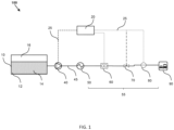
- the direct-fill fueling station 100 comprises an insulated tank 10, a control unit or system 20, a pump 40, at least one heat exchanger 50, a flow meter 60, a flow control device 70, and at least one sensor 80 for testing pressure and/or temperature.
- the flow meter 60, the flow control device 70, the at least one sensor 80, and optionally the heat exchanger 50 can be referred as a dispensing unit 55.
- the flow control device 70 and at least one sensor 80 can be a part of a nozzle configured into or in contact with an onboard tank of a vehicle 90.
- the insulated tank 10 is configured to store a liquefied fuel 12 comprising a liquid phase 14 and a gaseous phase 16 therein.
- the pump 40 is configured to pump out the liquefied fuel 12 from the insulated tank.
- the at least a heat exchanger 50 is fluidly coupled or connected with the pump 40.
- the flow meter 60, a flow control device 70, and at least one sensor 80 for testing pressure and/or temperature are fluidly coupled or connected with each other and with the heat exchanger 50.
- the components fluidly coupled or connected together through pipes 45.
- the pump 40 is configured to provide a portion of the liquefied fuel 12.
- the at least one heat exchanger 50 converts the portion of the liquefied fuel 12 into a gaseous fuel (a compressed gas) at a desired pressure and temperature.
- the dispensing unit 55 is configured to dispense the gaseous fuel into an onboard fuel tank (or called a vehicle storage vessel) in a vehicle 90.
- the heat exchanger 50 is configured to vaporize the liquefied fuel 12 from the pump 40 before it is dispensed to the vehicle storage tank as a compressed gas.
- the flow control device 70 and the at least one sensor 80 may be combined into a single nozzle.
- the station may include other apparatus such as a compressor (not shown).
- the exemplary station 100 further includes a control unit 20, which comprises one or more processors and at least one tangible, non-transitory machine readable medium encoded with one or more programs to be executed by the one or more processors as described below in FIG. 2 .
- the control unit 20 may be connected with the pump 40, the flow meter 60, the flow control device 70, and the at least one sensor 80 through electrical connection or wireless connection 25.
- the connection 25 in dotted lines is understood as wireless or electrical connections.
- the control unit 20 is configured to coordinate with the pump 40, the flow meter 60, the flow control device 70, and the at least one sensor 80 so as to control a method of fueling the vehicle 90.
- the control unit 20 may be electronically connected with other components, and such electronic connections may be through wire connection, wireless connection, and may include cloud based connection.
- the control unit 20 and other component can be also connected to an industrial control such as a programmable logic controller (PLC), which is supervised by a supervisory control and data acquisition (SCADA) computer with a human-machine interface (HMI).
- PLC programmable logic controller
- SCADA supervisory control and data acquisition
- HMI human-machine interface
- the electrical power demand of the exemplary station 100 is less than that determined by the product of a rated volumetric flow rate of the pump 40 and a rated pumping pressure adequate for a fill pressure of the vehicle.
- the pump 40 has a total electrical power demand being at least 90% of the electrical power demand of the station 10 during operation.
- the liquefied fuel is liquid hydrogen, and gaseous hydrogen is added into the tank of the vehicle 90 in some embodiments.
- the pump 40 may be any suitable pump, for example, a reciprocating pump, which is for a direct fill system.
- a reciprocating pump is a class of positive-displacement pumps. Examples of a reciprocating pump include, but are not limited to, a piston pump, a plunger pump, and a diaphragm pump.
- the station or system uses a peak electrical load less than the product of the maximum fill rate and maximum pumping pressure. It is not obvious how such large peak power demand can be reduced while meeting the fueling flow, pressure and fill time requirements.
- the enabling feature to overcome this limitation is the variable operation during the fill procedure.
- a reciprocating pump is operated at variable piston speeds and pumping pressure to meet constraints around the overall or average fill rate and final fill pressure, while simultaneously requiring peak electrical loads less than the product of the maximum instantaneous fill rate during the cycle and the maximum pumping pressure.
- the electrical power demand is at least 25% less than the product of the rated volumetric flow rate of the pump 40 and the rated pumping pressure adequate for the fill pressure of the vehicle.
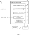
- Such a control unit 20 includes one or more processors 22, and at least one tangible, non-transitory machine readable medium encoded with one or more programs 34, to be executed by the one or more processors, to perform the functions or the method as described above.
- the processor(s) 22 may include a power demand control 24, which includes a parameter input module 26, models and simulator 28, a parameter output and control module 30, and information and instruction module 32.
- the parameter input and output modules 26 and 30 coordinate with the pump 40, the flow meter 60, the flow control device 70, and the at least one sensor 80.
- the models and simulator 28 is configured to perform a simulation based on the input parameters to provide information and instruction to the information and instruction module 32.
- the processors 22 may be connected with one or more displays 36 for displaying the information and instructions from module 32 and to an operator.
- control unit 20 is configured to set a pressure ramp profile or a mass flow rate profile of the gaseous fuel added to the onboard fuel tank so as to control the electrical power demand of the station 10.
- the control unit 20 can also be configured to output the pressure ramp profile or the mass flow rate profile for fueling a vehicle, and status information including the state of charge (SOC) during a fill process.
- SOC state of charge
- control unit 20 is configured to control the electrical power demand of the station by increasing the flow rate of the gaseous fuel at a beginning of a fill process at a low pressure, then reducing the flow rate near an end of the fill process at a high pressure.
- the instantaneous power requirement is substantially constant during the fill process in some embodiments.
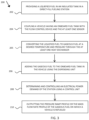
- an exemplary method 200 is used sizing and/or operating a direct-fill fueling station 100.
- the method of sizing can be used at the design stage in some embodiments.
- Such a method 200 comprises steps as described herein.
- a liquefied fuel 12 comprising a liquid phase and a gaseous phase is provided in an insulated tank 10 in a direct-fill fueling station 100.
- the direct-fill station 100 further comprises a pump 40, at least one heat exchanger 50, a flow meter 60, a flow control device 70, and at least one sensor 80 for testing pressure and/or temperature.
- a vehicle 90 having an onboard fuel tank is coupled with the flow control device 70 and the at least one sensor 80.
- the portion of the liquefied fuel 12 from the pump 40 is converted into a gaseous fuel (a compressed gas) at a desired pressure and temperature using at least one heat exchanger 50.
- the gaseous fuel 12 is added to the onboard fuel tank in the vehicle 90 the dispensing unit pump 55.
- an electrical power demand of the station is determined and/or controlled using a control unit 20.
- the control unit 20 comprises one or more processors 20 and at least one tangible, non-transitory machine readable medium encoded with one or more programs 34 to be executed by the one or more processors 20.
- the control unit 20 coordinates with the pump 40, the flow meter 60, the flow control device 70, and the at least one sensor 80.
- the electrical power demand of the station 100 is less than that determined by the product of a rated volumetric flow rate of the pump 40 and a rated pumping pressure adequate for a fill pressure of the vehicle 90.
- the electrical power demand of the station 100 is determined and controlled by setting up a pressure ramp profile or a mass flow rate profile (or volumetric flow rate) of the gaseous fuel added to the onboard fuel tank.
- the volumetric flow rate of the liquefied fuel 12 though the pump 40 can be calculated from the mass flow rate of the gaseous fuel though the mass balance.
- the electrical power demand of the station is determined and controlled by increasing the flow rate of the gaseous fuel into the vehicle tank (i.e. also the flow rate of the liquefied fuel from the pump) at a beginning of a fill process at a low pressure, then reducing the flow rate near an end of the fill process at a high pressure.
- the instantaneous power requirement is substantially constant during the fill process.
- the flow rate can be increased by increasing average pressure ramp rate (APRR) in some embodiments.
- APRR average pressure ramp rate
- the pressure profile can be adjusted with a liner increase (see Example 1).
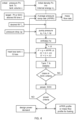
- the step 208 of determining and controlling the electrical power demand of the station using the control unit comprises the following steps (as also illustrated in Example 1):
- the pressure ramp profile (or flow rate profile) of the gaseous fuel is adjusted by going back to step (c) so that the electrical power demand of the station is substantially constant during the fill process, while the target fill time and target SOC are achieved.
- the power demand W for the pump (in kW) is calculated based on is the volumetric flow rate Q (in m 3 /hr) of the liquefied fuel, the difference ⁇ P between the inlet pressure and the pump pressure, and the pump efficiency ⁇ (%), which can be fixed (e.g., 70%, 80%, 90%, or 100%).
- the volumetric flow rate Q of the liquefied fuel 12 though the pump 40 can be calculated from the mass flow rate of the gaseous fuel though the mass balance.
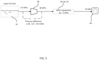
- the pump pressure needed is also provided based on the needs. For example, for the illustration purpose only, FIG. 5 shows one example.
- the inlet pressure of the liquefied fuel 12 before the pump 40 is very low, for example, 0.5MPa illustrated in FIG. 5 .
- the fill pressure of the onboard tank of the vehicle 90 may be 35 MPa (i.e. 350 bar) based on the requirement. Between the pump 40 and the vehicle 90, there might be a pressure drop, for example, 5 MPa as illustrated in FIG. 5 . Such a pressure drop may be caused by other components such as heat exchanger 50, flow meter 60 and flow control device 70. When the pressure drop is zero or negligible, the pump pressure and fill pressure are the same. Based on the pump pressure and the inlet pressure, the pressure difference needed in Equation (I) can be calculated. Therefore, the power demand at each time interval can be calculated.
- the method including the steps above can be used at a stage of designing a station 100.
- a peak electrical power demand (or requirement) of the station is determined as a rated power requirement through simulation.
- a curve of power demand including the peak power demand as the rated power requirement can be output from the exemplary control unit 200 in FIG. 2 .
- the rated power requirement is the maximum of the instantaneous power demand during the simulated fill, which is less than the product of the maximum flow and the maximum discharge pressure of the pump.
- the rated electrical power requirement is less than the product of the rated volumetric flow rate of the pump and the rated pumping pressure adequate for the vehicle fill pressure.
- the method 200 further comprises outputting the pressure ramp profile or the mass or volumetric flow rate profile of the gaseous fuel on which a vehicle is refueled.
- a profile can be selected by the control unit or by an operator for fueling a vehicle.
- the total electrical power demand of the pump 40 is at least 90% of the electrical power demand of the station during a filling cycle.
- the pump is a reciprocating pump.
- the liquefied fuel comprises or is liquid hydrogen, and gaseous hydrogen is added into a vehicle.
- the electrical power demand is at least 25% less than the product of the rated volumetric flow rate of the pump 40 and the rated pumping pressure adequate for the fill pressure of the vehicle 90.
- the reciprocating pump is operated in a manner that delivers H 2 at a non-constant mass flow rate during the filling cycle.
- the peak mass flow rate from the pump exceeds the rated maximum mass flow rate of the pump during at least part of the filling cycle.
- the average flow rate during the first part of the fill cycle (by time) is higher than average fill rate for the entire cycle.
- a simulation of the entire fueling cycle under different possible scenarios in the present disclosure shows that peak flow and peak pressure never coincide. They not only occur at different times during the fill cycle, but also trend in opposite directions. When peak flow is required, the pressure against which the hydrogen pump operates is low, and vice versa.
- piston seal wear in the reciprocating liquid hydrogen pump is proportional to pump discharge pressure and piston velocity.
- the piston velocity can be increased beyond design level while maintaining equal or better seal wear, thus increasing pump flow at low pressure to allow lower flow rate at high pressure for a lower peak power demand without sacrificing seal life.
- both the power demand and the piston seal wear are controlled by adjusting and the pump pressure and flow rate.
- the two-fold considerations are combined to provide a method to reduce the peak power demand while meeting fueling requirements.
- the instantaneous electrical load needed to operate the reciprocating pump during the filling cycle is the product of the instantaneous flow rate and the instantons pumping pressure.
- the instantaneous electrical load or the maximum power needed is less than the product of the overall or average design flow rate and design pumping pressure. This means the peak electrical load is less than said product, and that the electrical supply and electrical drive equipment to the refueling system can be sized at a smaller level than practiced in the existing technologies.
- the present disclosure also provides the control unit or a computer implemented system 20 as described herein.
- the control unit or system 20 comprises at least one tangible, non-transitory machine readable medium encoded with one or more programs 34 for performing the methods disclosed herein.
- the control unit 20 is used in a direct-fill fueling station for refueling a vehicle with fuel such as hydrogen.
- the beneficial result of the invention is that the peak electrical load required by the system during a fill cycle is less than the electrical load indicated by the product of the average fill rate and pumping pressure. This reduces the size of the electrical load that must be provided to the station to allow operation as well as peak electrical demand charges.
- the peak flow rate and peak pressure do not coincide during a filling cycle.
- the pump is operated in such a way that that the flow rate is higher earlier in the filling cycle.
- the peak electrical load for the pump (and the overall system) is reduced at levels below the theoretical estimate provided by the product of the average fill rate and fill pressure.
- the station or system provided herein can be a high-flow direct fill system with large capacity stations for fueling fuel such as hydrogen, with minimal and stable electrical power demand. It can be used for fueling or refueling a vehicle efficiently and fast.
- a direct-fill system including a reciprocating pump as described above was used for refueling hydrogen for vehicles.
- references to a pressure value with a unit such as bar, bar(g) and barg are understood as gauge pressure, which is a pressure in bars above ambient or atmospheric pressure. Pump rated flow is equivalent to design pump flow.
- REFPROP Reference Fluid Thermodynamic and Transport Properties
- Compression equipment capacity was determined using the maximum rated flow of the pump and the maximum pressure that the pump experiences following a general procedure.
- a calculation was performed for a refueling station with direct fill option using a reciprocating pump operating at a pump design flow ( ⁇ ) of 240 kg/hr and a maximum pumping pressure (p) of 400 bar (40 MPa).
- a system pressure drop of 50 bar (5 MPa) was assumed above the final fill pressure of the vehicle storage tank for a vehicle of 350 bar (35 MPa) nominal fill pressure (also known as H35).
- fuel cell electrical vehicles may have a range of storage sizes and they may come to the refueling station at different states of charge (SOC), which are defined as the ratio of actual density in the vehicle storage tank to that at 350 bar (35 MPa) and 15 °C.
- SOC states of charge
- Example 1 it was assumed that the capacity of the largest vehicle storage tank to be filled is 1200 liters, the tank is filled nominally to 350 bar, and the vehicle comes to the station at 5 bar (0.5 MPa) in its storage tank (SOC at ⁇ 2%). The desired final SOC is 95%, which allows 26.7 kg of hydrogen to be added. The desired fill time is set to 6.7 minutes to be consistent with the Comparative Example.
- ⁇ pM / RT
- R the universal gas constant
- M the molecular weight.
- ideal gas equation of state is inappropriate, and the equation of state explicit in Helmholtz energy, the modified Benedict-Webb-Rubin equation of state, or the extend corresponding states as implemented in the REFPROP thermodynamic database package is used.
- V known tank size
- V initial tank mass
- u internal energy
- An average pressure ramp rate (APRR) rate is defined based on initial vehicle storage tank pressure, target fill pressure, and fill time. The initial vehicle storage tank pressure used was 5 bar (0.5 MPa), and the fill time used was 6.7 minutes in Example 1.
- a desired fill temperature at the nozzle (T n ) is set to be a suitable temperature, for example, -40 °C in Example 1.
- the modeling or calculation is then advanced to the next time step ⁇ t .
- the pressure at the vehicle storage tank (p) is p+APRR* ⁇ t .
- a mass change ⁇ m is estimated so that now the mass in the vehicle storage tank (m) is m+ ⁇ m.
- the internal energy of the vehicle storage tank (u) is u+hz*[1+(u/hz-1)*Qloss], where Qloss is a heat loss factor.
- Qloss is set to 0
- the fueling process is adiabatic.
- Qloss is set to 1.0
- the heat loss is not necessarily a linear function of this factor.
- Qloss is set to 90% to match the observation that H35 filling with no precooling would not exceed 85 °C in the vehicle storage tank.
- the gaseous hydrogen fuel is dispensed in a compressed gas. Sometimes the vehicle storage tank experiences heating because of the compression. In some embodiments, precooling of the gaseous fuel may be used.
- the vehicle storage tank temperature and density are calculated based on the updated pressure and internal energy.
- the mass in the vehicle storage tank is calculated based on the calculated density and tank volume.
- the mass change ⁇ m is iterated until this calculated mass matches that of step 7.
- the time is advanced by ⁇ t and repeat steps 7 through 10 until SOC and fill time targets are achieved.
- the final pressure in the vehicle storage tank is 361 bar, and the temperature is 43.7 °C (with fuel precooled to -40 °C).
- the vehicle tank pressure, temperature, and instantaneous motor power demand are shown in FIG. 6 .
- the peak power demand occurs at the end of the fill when the pump is pushing against the maximum resistance.
- Vehicle tank pressure, total mass, and SOC at different filling time intervals are shown in FIG. 7 . It is clear that peak mass flow occurs at the beginning of the fill when the vehicle tank pressure is the lowest, while mass flow is the lowest when the vehicle tank pressure is the highest at the end of the fill.
- Example 1 when an empty tank is filled by controlling a linear increase in the pump pressure, the peak mass flow and the peak pressure do not coincide. This is desired that the use of a reciprocating pump provides such results.
- Example 2 The same calculation procedure in Example 1 was repeated for a vehicle initial pressure of 50 bar (initial SOC 17%), holding all other parameters the same as above.
- the final vehicle storage tank pressure is 354 bar
- the maximum temperature is 38.2 °C
- the peak motor power demand is 79.3 kW. 22.5 kg of hydrogen was filled.
- Example 1 The calculation procedure in Example 1 was repeated with the same parameters of Example 1 except making the fill time as 5 minutes. The same calculation procedure results in peak motor power demand 123.8 kW. Peak mass flow is now 406 kg/hr, much higher than the pump rating.
- Example 2 Using the same calculation procedure and all parameters the same as those in Example 1 except the fuel temperature 25 °C, the calculation was performed. The calculation results in peak motor power demand 98.2 kW. The final vehicle storage tank pressure is 394 bar (39.4 MPa), and the temperature is 71.3 °C.
- Example 5 Faster flow during initial part of the fill.
- the mass flow rate is increased for the first period of time (e.g., ⁇ minutes) of the fill by increasing the pressure ramp rate.
- the maximum ramp rate multiplier is set to be ⁇ .
- the first period of time ( ⁇ ) is 3 minutes
- the maximum ramp rate multiplier ( ⁇ ) is set to be 2
- the peak motor power demand becomes 76.1 kW.
- the final vehicle tank pressure is 361 bar, and the temperature is 43.5 °C.
- the peak mass flow rate is now 493 kg/hr.
- the vehicle tank pressure, temperature, and instantaneous motor power demand are shown in FIG. 8 .
- Vehicle tank pressure, total mass, and SOC at different filling time intervals are shown in FIG. 9 .
- the maximum ramp rate multipler cannot be increased much further as it produces a local maximum in the power curve. That value is now 66.9 kW.
- Fast initial flow for the initial part of fill results in lower motor power demand.
- More nuanced control algorithms can be devised to flatten the power curve and reduce the peak power demand further.
- the peak mass flow and the peak pressure do not coincide.
- Fast initial fill reduces mass flow and power at high pressure.
- the first period of time can be pre-determined before calculation. Repeated calculation can be done by selecting different first period of time. The optimal first period of time can be then determined.
- the method of Example 5 is preferred in some embodiments.
- the motor power demand in the examples is lower than that of the Comparative Example, and does not get to the high level as determined in existing technologies. Furthermore, increasing fueling rates at the beginning of the fill when vehicle storage tank pressure is low reduces the peak motor power demand.
- the method using a control strategy as illustrated in Example 4 further reduces the power demand by 18%, relative to Example 1.
- the methods and system described herein may be at least partially embodied in the form of computer-implemented processes and apparatus for practicing those processes.
- the disclosed methods may also be at least partially embodied in the form of tangible, non-transient machine readable storage media encoded with computer program code.
- the media may include, for example, RAMs, ROMs, CD-ROMs, DVD-ROMs, BD-ROMs, hard disk drives, flash memories, or any other non-transient machine-readable storage medium, or any combination of these mediums, wherein, when the computer program code is loaded into and executed by a computer, the computer becomes an apparatus for practicing the method.
- the methods may also be at least partially embodied in the form of a computer into which computer program code is loaded and/or executed, such that, the computer becomes an apparatus for practicing the methods.
- the computer program code segments configure the processor to create specific logic circuits.
- the methods may alternatively be at least partially embodied in a digital signal processor formed of application specific integrated circuits for performing the methods.
- the computer or the control unit may be operated remotely using a cloud based system.
Landscapes
- Engineering & Computer Science (AREA)
- Mechanical Engineering (AREA)
- General Engineering & Computer Science (AREA)
- Physics & Mathematics (AREA)
- Thermal Sciences (AREA)
- Filling Or Discharging Of Gas Storage Vessels (AREA)
Claims (14)
- Eine Direktbetankungsstation (100) umfassend:einen isolierten Behälter (10), der eingerichtet ist, darin einen verflüssigten Kraftstoff, der eine flüssige Phase und eine gasförmige Phase enthält, zu speichern;eine Pumpe (40), die eingerichtet ist, einen Teil des verflüssigten Kraftstoffs aus dem isolierten Behälter (10) herauszupumpen;mindestens einen Wärmetauscher (50), der mit der Pumpe (40) verbunden ist und eingerichtet ist, den Anteil des verflüssigten Kraftstoffs in einen gasförmigen Kraftstoff umzusetzen;eine Abgabeeinheit (55), die einen Durchflussmesser (60), eine Durchflusssteuervorrichtung (70) und mindestens einen Sensor (80) zum Prüfen von Druck und Temperatur, die mit dem Wärmetauscher (50) verbunden sind, umfasst, wobei die Abgabeeinheit (55) eingerichtet ist, den gasförmigen Kraftstoff in einen Bordkraftstoffbehälter in einem Fahrzeug hinzuzufügen; undeine Steuereinheit (20), die einen oder mehrere Prozessoren (22) umfasst und mindestens ein materielles, nichtflüchtiges, maschinenlesbares Medium umfasst, das mit einem oder mehreren Programmen codiert ist, die durch den einen oder die mehreren Prozessoren ausgeführt werden sollen, um mit der Pumpe (40), dem Durchflussmesser (60), der Durchflusssteuervorrichtung (70) und dem mindestens einen Sensor (80) zu koordinieren, um ein Verfahren zum Betanken des Fahrzeugs zu steuern, wobei eine elektrische Leistungsaufnahme der Station (100) kleiner als diejenige ist, die durch das Produkt einer volumetrischen Nenndurchflussmenge der Pumpe (40) und eines Nennpumpendrucks, der für einen Fülldruck des Fahrzeugs angemessen ist, bestimmt ist, wobei die Steuereinheit (20) eingerichtet ist, die elektrische Leistungsaufnahme der Station zu bestimmen und zu steuern durch:Eingeben des Ausgangsbehälterdrucks, der Ausgangsbehältertemperatur, des Volumens des isolierten Behälters (10), einer gewünschten Füllzeit, eines Solldrucks oder eines Sollladezustands (Soll-SOC);Berechnen der Ausgangsdichte, der Gesamtmasse und der inneren Energie des verflüssigten Kraftstoffs im Bordkraftstoffbehälter;Einstellen eines Druckanstiegsprofils des gasförmigen Kraftstoffs, der zum Bordkraftstoffbehälter hinzugefügt wird, um die angestrebte Füllzeit zu erzielen;Einstellen einer gewünschten Fülltemperatur an einer Düse;Einstellen des Pumpenauslassdrucks ausreichend hoch, um einen Systemdruckverlust vom Pumpenausfluss zur Düse zu überwinden, um einen gewünschten Düsendruck zu erzielen;Berechnen der Enthalpie des gasförmigen Kraftstoffs auf der Grundlage der gewünschten Fülltemperatur an der Düse und des Pumpenauslassdrucks;Verstreichenlassen eines Zeitintervalls;Anwenden eines Masse/Energie-Ausgleichs auf den Bordkraftstoffbehälter, nachdem das Zeitintervall verstrichen ist, wahlweise unter Berücksichtigung eines Wärmeverlusts;Bestimmen einer hinzugefügten Masse des gasförmigen Kraftstoffs, der in den Bordkraftstoffbehälter hinzugefügt worden ist; undAuswerten der momentanen elektrischen Leistungsaufnahme und des Ladezustands (SOC) und Wiederholen des Schritts des Verstreichenlassens eines Zeitintervalls, falls notwendig, um den Soll-SOC zu erreichen.
- Die Direktbetankungsstation nach Anspruch 1, wobei die elektrische Leistungsaufnahme mindestens um 25 % kleiner ist als das Produkt der volumetrischen Nenndurchflussmenge der Pumpe (40) und des Nennpumpendrucks, der für den Fülldruck des Fahrzeugs angemessen ist.
- Die Direktbetankungsstation nach Anspruch 1, wobei die Steuereinheit (20) eingerichtet ist, ein Massendurchflussmengenprofil des gasförmigen Kraftstoffs, der zum Bordkraftstoffbehälter hinzugefügt wird, einzustellen, um die elektrische Leistungsaufnahme der Station zu steuern.
- Die Direktbetankungsstation nach Anspruch 3, wobei die Steuereinheit (20) konfiguriert ist, das Druckanstiegsprofil oder das Massendurchflussmengenprofil zum Betanken eines Fahrzeugs und Zustandsinformationen, die den Ladezustand (SOC) enthalten, während eines Füllvorgangs auszugeben.
- Die Direktbetankungsstation nach Anspruch 3, wobei die Steuereinheit (20) eingreichtet ist, die elektrische Leistungsaufnahme der Station zu steuern, indem die Durchflussmenge des gasförmigen Kraftstoffs zu Beginn eines Füllvorgangs bei einem niedrigen Druck erhöht wird und anschließend die Durchflussmenge in der Nähe des Endes des Füllvorgangs bei einem hohen Druck verringert wird.
- Die Direktbetankungsstation nach Anspruch 5, wobei ein momentaner Leistungsbedarf während des Füllvorgangs im Wesentlichen konstant ist.
- Ein Verfahren zum Bemessen und Betreiben einer Direktbetankungsstation (100), das die folgenden Schritte umfasst:Bereitstellen eines Anteils eines verflüssigten Kraftstoffs, der eine flüssige Phase und eine gasförmige Phase enthält, der in einem isolierten Behälter (10) in einer Direktbetankungsstation (100) gespeichert ist, wobei die Direktstation (100) ferner eine Pumpe (40), mindestens einen Wärmetauscher (50), der mit der Pumpe (40) verbunden ist, und eine Abgabeeinheit (55), die einen Durchflussmesser (60), eine Durchflusssteuervorrichtung (70) und mindestens einen Sensor (80) zum Prüfen von Druck und Temperatur, die mit dem Wärmetauscher (50) verbunden sind, enthält, umfasst;Koppeln eines Fahrzeugs, das einen Bordkraftstoffbehälter aufweist, mit der Durchflusssteuervorrichtung (70) und dem mindestens einen Sensor (80);Umsetzen des Anteils des verflüssigten Kraftstoffs in einen gasförmigen Kraftstoff in dem mindestens einen Wärmetauscher (50);Hinzufügen des gasförmigen Kraftstoffs zum Bordkraftstoffbehälter im Fahrzeug unter Verwendung der Abgabeeinheit (55); undBestimmen und Steuern einer elektrischen Leistungsaufnahme der Station (100) unter Verwendung einer Steuereinheit (20), wobei die Steuereinheit (20) einen oder mehrere Prozessoren (22) umfasst und mindestens ein materielles, nichtflüchtiges, maschinenlesbares Medium umfasst, das mit einem oder mehreren Programmen codiert ist, die durch den einen oder die mehreren Prozessoren ausgeführt werden sollen, um mit der Pumpe (40), dem Durchflussmesser (60), der Durchflusssteuervorrichtung (70) und dem mindestens einen Sensor (80) zu koordinieren, derart, dass die elektrische Leistungsaufnahme der Station (100) kleiner als diejenige ist, die durch das Produkt einer volumetrischen Nenndurchflussmenge der Pumpe (40) und eines Nennpumpendrucks, der für einen Fülldruck des Fahrzeugs angemessen ist, bestimmt ist, wobei der Schritt des Bestimmens und Steuerns der elektrischen Leistungsaufnahme der Station unter Verwendung der Steuereinheit (20) die folgenden Schritte umfasst:Eingeben des Ausgangsbehälterdrucks, der Ausgangsbehältertemperatur, des Volumens des isolierten Behälters, einer gewünschten Füllzeit, eines Solldrucks oder eines Sollladezustands (Soll-SOC);Berechnen der Ausgangsdichte, der Gesamtmasse und der inneren Energie des verflüssigten Kraftstoffs im Bordkraftstoffbehälter;Einstellen eines Druckanstiegsprofils des gasförmigen Kraftstoffs, der zum Bordkraftstoffbehälter hinzugefügt wird, um die angestrebte Füllzeit zu erzielen;Einstellen einer gewünschten Fülltemperatur an einer Düse;Einstellen des Pumpenauslassdrucks ausreichend hoch, um einen Systemdruckverlust vom Pumpenausfluss zur Düse zu überwinden, um einen gewünschten Düsendruck zu erzielen;Berechnen der Enthalpie des gasförmigen Kraftstoffs auf der Grundlage der gewünschten Fülltemperatur an der Düse und des Pumpenauslassdrucks;Verstreichenlassen eines Zeitintervalls;Anwenden eines Masse/Energie-Ausgleichs auf den Bordkraftstoffbehälter, nachdem das Zeitintervall verstrichen ist, wahlweise unter Berücksichtigung eines Wärmeverlusts;Bestimmen einer hinzugefügten Masse des gasförmigen Kraftstoffs, der in den Bordkraftstoffbehälter hinzugefügt worden ist; undAuswerten der momentanen elektrischen Leistungsaufnahme und des Ladezustands (SOC), wahlweise Wiederholen des Schritts des Verstreichenlassens eines Zeitintervalls, falls notwendig, um den Soll-SOC zu erreichen.
- Das Verfahren nach Anspruch 7, wobei eine elektrische Gesamtleistungsaufnahme der Pumpe mindestens 90 % der elektrischen Leistungsaufnahme der Station während eines Füllzyklus ist.
- Das Verfahren nach Anspruch 7, wobei die elektrische Leistungsaufnahme mindestens um 25 % kleiner ist als das Produkt der volumetrischen Nenndurchflussmenge der Pumpe und des Nennpumpendrucks, der für den Fülldruck des Fahrzeugs angemessen ist.
- Das Verfahren nach Anspruch 7, wobei die elektrische Leistungsaufnahme der Station bestimmt und gesteuert wird, indem ein Massendurchflussmengenprofil des gasförmigen Kraftstoffs, der zum Bordkraftstoffbehälter hinzugefügt wird, eingerichtet wird.
- Das Verfahren nach Anspruch 10, wobei die elektrische Leistungsaufnahme der Station bestimmt und gesteuert wird, indem die Durchflussmenge des gasförmigen Kraftstoffs zu Beginn eines Füllvorgangs bei einem niedrigen Druck erhöht wird und anschließend die Durchflussmenge in der Nähe des Endes des Füllvorgangs bei einem hohen Druck verringert wird.
- Das Verfahren nach Anspruch 11, wobei ein momentaner Leistungsbedarf während des Füllvorgangs im Wesentlichen konstant ist.
- Das Verfahren nach Anspruch 7, wobei der Schritt des Bestimmens und Steuerns der elektrischen Leistungsaufnahme der Station unter Verwendung der Steuereinheit ferner das Einstellen des Druckanstiegsprofils, derart, dass die elektrische Leistungsaufnahme der Station während des Füllvorgangs im Wesentlichen konstant ist, während die Sollfüllzeit und der Soll-SOC erzielt werden, umfasst.
- Das Verfahren nach Anspruch 7, wobei eine elektrische Spitzenleistungsaufnahme der Station durch Simulation als ein Nennleistungsbedarf bestimmt wird.
Applications Claiming Priority (1)
| Application Number | Priority Date | Filing Date | Title |
|---|---|---|---|
| US17/136,070 US11391415B1 (en) | 2020-12-29 | 2020-12-29 | Method for minimizing power demand for hydrogen refueling station |
Publications (2)
| Publication Number | Publication Date |
|---|---|
| EP4023928A1 EP4023928A1 (de) | 2022-07-06 |
| EP4023928B1 true EP4023928B1 (de) | 2024-06-05 |
Family
ID=74591899
Family Applications (1)
| Application Number | Title | Priority Date | Filing Date |
|---|---|---|---|
| EP21156634.4A Active EP4023928B1 (de) | 2020-12-29 | 2021-02-11 | Verfahren zur minimierung des leistungsbedarfs für eine wasserstofftankstelle |
Country Status (3)
| Country | Link |
|---|---|
| US (1) | US11391415B1 (de) |
| EP (1) | EP4023928B1 (de) |
| CN (1) | CN114754285B (de) |
Families Citing this family (4)
| Publication number | Priority date | Publication date | Assignee | Title |
|---|---|---|---|---|
| CN115210733A (zh) * | 2020-09-04 | 2022-10-18 | 现代格罗唯视株式会社 | 供氢网络管理优化平台及其方法 |
| US12066152B2 (en) * | 2020-10-27 | 2024-08-20 | H2 Clipper, Inc. | Method and apparatus for delivering hydrogen |
| US12595884B2 (en) * | 2022-10-06 | 2026-04-07 | General Electric Company | Methods, apparatus, systems, and articles of manufacture to produce cryo-compressed hydrogen |
| AU2024265029A1 (en) | 2023-05-04 | 2025-12-18 | H2C Safety Pipe, Inc. | Method and apparatus for delivering hydrogen |
Family Cites Families (10)
| Publication number | Priority date | Publication date | Assignee | Title |
|---|---|---|---|---|
| US6354088B1 (en) * | 2000-10-13 | 2002-03-12 | Chart Inc. | System and method for dispensing cryogenic liquids |
| US6810924B2 (en) | 2003-03-17 | 2004-11-02 | Praxair Technology, Inc. | Compressed gas stream introduction method and filling station |
| US6899146B2 (en) | 2003-05-09 | 2005-05-31 | Battelle Energy Alliance, Llc | Method and apparatus for dispensing compressed natural gas and liquified natural gas to natural gas powered vehicles |
| US9347614B2 (en) * | 2010-04-21 | 2016-05-24 | Honda Motor Co., Ltd. | Method and system for tank refilling using active fueling speed control |
| JP5759741B2 (ja) | 2011-02-16 | 2015-08-05 | 岩谷産業株式会社 | 燃料用水素ガス充填装置及び燃料用水素ガス充填方法 |
| US20160273713A1 (en) | 2013-10-28 | 2016-09-22 | Alternative Fuel Containers, Llc | Fuel gas tank filling system and method |
| CN108916643A (zh) * | 2018-07-13 | 2018-11-30 | 北京航天试验技术研究所 | 液态储氢加氢站 |
| FR3086367B1 (fr) | 2018-09-25 | 2020-09-11 | Air Liquide | Dispositif et procede de remplissage de reservoirs de gaz sous pression |
| US10961109B2 (en) | 2018-11-16 | 2021-03-30 | China Energy Investment Corporation Limited | Fluid bypass method and system for controlling the temperature of a non-petroleum fuel |
| US11009185B2 (en) * | 2018-11-16 | 2021-05-18 | China Energy Investment Corporation Limited | Method and system of dispensing liquefied gas |
-
2020
- 2020-12-29 US US17/136,070 patent/US11391415B1/en active Active
-
2021
- 2021-01-28 CN CN202110116043.6A patent/CN114754285B/zh active Active
- 2021-02-11 EP EP21156634.4A patent/EP4023928B1/de active Active
Also Published As
| Publication number | Publication date |
|---|---|
| US11391415B1 (en) | 2022-07-19 |
| US20220205591A1 (en) | 2022-06-30 |
| CN114754285A (zh) | 2022-07-15 |
| EP4023928A1 (de) | 2022-07-06 |
| CN114754285B (zh) | 2024-07-12 |
Similar Documents
| Publication | Publication Date | Title |
|---|---|---|
| US11391415B1 (en) | Method for minimizing power demand for hydrogen refueling station | |
| KR102566242B1 (ko) | 액화가스를 분배하는 방법 및 시스템 | |
| CN112789444B (zh) | 用于储存和分配液化氢的方法和设施 | |
| US9458968B2 (en) | Hydrogen dispensing process and system | |
| Petitpas | Boil-off losses along LH2 pathway | |
| Hosseini et al. | Thermodynamic analysis of filling compressed gaseous hydrogen storage tanks | |
| US10961109B2 (en) | Fluid bypass method and system for controlling the temperature of a non-petroleum fuel | |
| Li et al. | Effects of geometry and inconstant mass flow rate on temperatures within a pressurized hydrogen cylinder during refueling | |
| Yu et al. | Optimization on volume ratio of three-stage cascade storage system in hydrogen refueling stations | |
| US20170130901A1 (en) | Fuel refilling systems and methods | |
| Zheng et al. | An optimized control method for a high utilization ratio and fast filling speed in hydrogen refueling stations | |
| EP4019824B1 (de) | System und verfahren zur vorkühlung einer benzinzapfsäule | |
| Park et al. | Investigation of configuration on multi-tank cascade system at hydrogen refueling stations with mass flow rate | |
| CN115596990B (zh) | 用于液化气体储存的具有汽化管理的系统和方法 | |
| CN115164088B (zh) | 储氢系统及其快速加氢过程的压力和温度优化控制方法 | |
| EP3722653A1 (de) | Kombiniertes wasserstoffspeicher- und kompressionssystem zum befüllen von hochdruckwasserstofftanks | |
| CN105179930A (zh) | 液化天然气和压缩天然气合建站的液化天然气槽车卸车装置及应用 | |
| Galanido et al. | Fuel filling time estimation for hydrogen-powered fuel cell electric vehicle at different initial conditions using dynamic simulation | |
| Yang et al. | Refueling process analysis and parameter optimization in liquid hydrogen refueling stations utilizing gas-liquid hydrogen mixed pre-cooling | |
| CN108225470A (zh) | 一种氢气循环疲劳测试系统中氢气储罐容积计算方法 | |
| Daney et al. | Hydrogen vehicle fueling station | |
| EP3769003A1 (de) | Druckbehälter für flüssiggas und verbraucheranschluss | |
| WO2025250856A1 (en) | Hydrogen refueling system and method for uses in different climates | |
| Chen et al. | Optimization of hydrogen utilization ratio in hydrogen filling stations | |
| Ferreiraa et al. | Development of a numerical optimization model for sizing hydrogen refuelling stations: application to a case study |
Legal Events
| Date | Code | Title | Description |
|---|---|---|---|
| PUAI | Public reference made under article 153(3) epc to a published international application that has entered the european phase |
Free format text: ORIGINAL CODE: 0009012 |
|
| STAA | Information on the status of an ep patent application or granted ep patent |
Free format text: STATUS: THE APPLICATION HAS BEEN PUBLISHED |
|
| AK | Designated contracting states |
Kind code of ref document: A1 Designated state(s): AL AT BE BG CH CY CZ DE DK EE ES FI FR GB GR HR HU IE IS IT LI LT LU LV MC MK MT NL NO PL PT RO RS SE SI SK SM TR |
|
| STAA | Information on the status of an ep patent application or granted ep patent |
Free format text: STATUS: REQUEST FOR EXAMINATION WAS MADE |
|
| 17P | Request for examination filed |
Effective date: 20221220 |
|
| RBV | Designated contracting states (corrected) |
Designated state(s): AL AT BE BG CH CY CZ DE DK EE ES FI FR GB GR HR HU IE IS IT LI LT LU LV MC MK MT NL NO PL PT RO RS SE SI SK SM TR |
|
| RIC1 | Information provided on ipc code assigned before grant |
Ipc: F17C 5/00 20060101AFI20231127BHEP |
|
| GRAP | Despatch of communication of intention to grant a patent |
Free format text: ORIGINAL CODE: EPIDOSNIGR1 |
|
| STAA | Information on the status of an ep patent application or granted ep patent |
Free format text: STATUS: GRANT OF PATENT IS INTENDED |
|
| RAP3 | Party data changed (applicant data changed or rights of an application transferred) |
Owner name: NATIONAL INSTITUTE OF CLEAN-AND-LOW-CARBON ENERGY Owner name: CHINA ENERGY INVESTMENT CORPORATION LIMITED |
|
| INTG | Intention to grant announced |
Effective date: 20240115 |
|
| GRAS | Grant fee paid |
Free format text: ORIGINAL CODE: EPIDOSNIGR3 |
|
| GRAA | (expected) grant |
Free format text: ORIGINAL CODE: 0009210 |
|
| STAA | Information on the status of an ep patent application or granted ep patent |
Free format text: STATUS: THE PATENT HAS BEEN GRANTED |
|
| AK | Designated contracting states |
Kind code of ref document: B1 Designated state(s): AL AT BE BG CH CY CZ DE DK EE ES FI FR GB GR HR HU IE IS IT LI LT LU LV MC MK MT NL NO PL PT RO RS SE SI SK SM TR |
|
| REG | Reference to a national code |
Ref country code: CH Ref legal event code: EP |
|
| REG | Reference to a national code |
Ref country code: DE Ref legal event code: R096 Ref document number: 602021013958 Country of ref document: DE |
|
| REG | Reference to a national code |
Ref country code: IE Ref legal event code: FG4D |
|
| REG | Reference to a national code |
Ref country code: LT Ref legal event code: MG9D |
|
| PG25 | Lapsed in a contracting state [announced via postgrant information from national office to epo] |
Ref country code: BG Free format text: LAPSE BECAUSE OF FAILURE TO SUBMIT A TRANSLATION OF THE DESCRIPTION OR TO PAY THE FEE WITHIN THE PRESCRIBED TIME-LIMIT Effective date: 20240605 |
|
| REG | Reference to a national code |
Ref country code: NL Ref legal event code: MP Effective date: 20240605 |
|
| PG25 | Lapsed in a contracting state [announced via postgrant information from national office to epo] |
Ref country code: HR Free format text: LAPSE BECAUSE OF FAILURE TO SUBMIT A TRANSLATION OF THE DESCRIPTION OR TO PAY THE FEE WITHIN THE PRESCRIBED TIME-LIMIT Effective date: 20240605 Ref country code: FI Free format text: LAPSE BECAUSE OF FAILURE TO SUBMIT A TRANSLATION OF THE DESCRIPTION OR TO PAY THE FEE WITHIN THE PRESCRIBED TIME-LIMIT Effective date: 20240605 |
|
| PG25 | Lapsed in a contracting state [announced via postgrant information from national office to epo] |
Ref country code: GR Free format text: LAPSE BECAUSE OF FAILURE TO SUBMIT A TRANSLATION OF THE DESCRIPTION OR TO PAY THE FEE WITHIN THE PRESCRIBED TIME-LIMIT Effective date: 20240906 |
|
| PG25 | Lapsed in a contracting state [announced via postgrant information from national office to epo] |
Ref country code: ES Free format text: LAPSE BECAUSE OF FAILURE TO SUBMIT A TRANSLATION OF THE DESCRIPTION OR TO PAY THE FEE WITHIN THE PRESCRIBED TIME-LIMIT Effective date: 20240605 |
|
| PG25 | Lapsed in a contracting state [announced via postgrant information from national office to epo] |
Ref country code: LV Free format text: LAPSE BECAUSE OF FAILURE TO SUBMIT A TRANSLATION OF THE DESCRIPTION OR TO PAY THE FEE WITHIN THE PRESCRIBED TIME-LIMIT Effective date: 20240605 |
|
| PG25 | Lapsed in a contracting state [announced via postgrant information from national office to epo] |
Ref country code: NO Free format text: LAPSE BECAUSE OF FAILURE TO SUBMIT A TRANSLATION OF THE DESCRIPTION OR TO PAY THE FEE WITHIN THE PRESCRIBED TIME-LIMIT Effective date: 20240905 Ref country code: LV Free format text: LAPSE BECAUSE OF FAILURE TO SUBMIT A TRANSLATION OF THE DESCRIPTION OR TO PAY THE FEE WITHIN THE PRESCRIBED TIME-LIMIT Effective date: 20240605 Ref country code: HR Free format text: LAPSE BECAUSE OF FAILURE TO SUBMIT A TRANSLATION OF THE DESCRIPTION OR TO PAY THE FEE WITHIN THE PRESCRIBED TIME-LIMIT Effective date: 20240605 Ref country code: GR Free format text: LAPSE BECAUSE OF FAILURE TO SUBMIT A TRANSLATION OF THE DESCRIPTION OR TO PAY THE FEE WITHIN THE PRESCRIBED TIME-LIMIT Effective date: 20240906 Ref country code: FI Free format text: LAPSE BECAUSE OF FAILURE TO SUBMIT A TRANSLATION OF THE DESCRIPTION OR TO PAY THE FEE WITHIN THE PRESCRIBED TIME-LIMIT Effective date: 20240605 Ref country code: ES Free format text: LAPSE BECAUSE OF FAILURE TO SUBMIT A TRANSLATION OF THE DESCRIPTION OR TO PAY THE FEE WITHIN THE PRESCRIBED TIME-LIMIT Effective date: 20240605 Ref country code: BG Free format text: LAPSE BECAUSE OF FAILURE TO SUBMIT A TRANSLATION OF THE DESCRIPTION OR TO PAY THE FEE WITHIN THE PRESCRIBED TIME-LIMIT Effective date: 20240605 Ref country code: RS Free format text: LAPSE BECAUSE OF FAILURE TO SUBMIT A TRANSLATION OF THE DESCRIPTION OR TO PAY THE FEE WITHIN THE PRESCRIBED TIME-LIMIT Effective date: 20240905 |
|
| PG25 | Lapsed in a contracting state [announced via postgrant information from national office to epo] |
Ref country code: NL Free format text: LAPSE BECAUSE OF FAILURE TO SUBMIT A TRANSLATION OF THE DESCRIPTION OR TO PAY THE FEE WITHIN THE PRESCRIBED TIME-LIMIT Effective date: 20240605 |
|
| REG | Reference to a national code |
Ref country code: AT Ref legal event code: MK05 Ref document number: 1692693 Country of ref document: AT Kind code of ref document: T Effective date: 20240605 |
|
| PG25 | Lapsed in a contracting state [announced via postgrant information from national office to epo] |
Ref country code: NL Free format text: LAPSE BECAUSE OF FAILURE TO SUBMIT A TRANSLATION OF THE DESCRIPTION OR TO PAY THE FEE WITHIN THE PRESCRIBED TIME-LIMIT Effective date: 20240605 |
|
| PG25 | Lapsed in a contracting state [announced via postgrant information from national office to epo] |
Ref country code: PT Free format text: LAPSE BECAUSE OF FAILURE TO SUBMIT A TRANSLATION OF THE DESCRIPTION OR TO PAY THE FEE WITHIN THE PRESCRIBED TIME-LIMIT Effective date: 20241007 |
|
| PG25 | Lapsed in a contracting state [announced via postgrant information from national office to epo] |
Ref country code: PT Free format text: LAPSE BECAUSE OF FAILURE TO SUBMIT A TRANSLATION OF THE DESCRIPTION OR TO PAY THE FEE WITHIN THE PRESCRIBED TIME-LIMIT Effective date: 20241007 |
|
| PG25 | Lapsed in a contracting state [announced via postgrant information from national office to epo] |
Ref country code: PL Free format text: LAPSE BECAUSE OF FAILURE TO SUBMIT A TRANSLATION OF THE DESCRIPTION OR TO PAY THE FEE WITHIN THE PRESCRIBED TIME-LIMIT Effective date: 20240605 |
|
| PG25 | Lapsed in a contracting state [announced via postgrant information from national office to epo] |
Ref country code: EE Free format text: LAPSE BECAUSE OF FAILURE TO SUBMIT A TRANSLATION OF THE DESCRIPTION OR TO PAY THE FEE WITHIN THE PRESCRIBED TIME-LIMIT Effective date: 20240605 |
|
| PG25 | Lapsed in a contracting state [announced via postgrant information from national office to epo] |
Ref country code: AT Free format text: LAPSE BECAUSE OF FAILURE TO SUBMIT A TRANSLATION OF THE DESCRIPTION OR TO PAY THE FEE WITHIN THE PRESCRIBED TIME-LIMIT Effective date: 20240605 Ref country code: IS Free format text: LAPSE BECAUSE OF FAILURE TO SUBMIT A TRANSLATION OF THE DESCRIPTION OR TO PAY THE FEE WITHIN THE PRESCRIBED TIME-LIMIT Effective date: 20241005 |
|
| PG25 | Lapsed in a contracting state [announced via postgrant information from national office to epo] |
Ref country code: CZ Free format text: LAPSE BECAUSE OF FAILURE TO SUBMIT A TRANSLATION OF THE DESCRIPTION OR TO PAY THE FEE WITHIN THE PRESCRIBED TIME-LIMIT Effective date: 20240605 |
|
| PG25 | Lapsed in a contracting state [announced via postgrant information from national office to epo] |
Ref country code: RO Free format text: LAPSE BECAUSE OF FAILURE TO SUBMIT A TRANSLATION OF THE DESCRIPTION OR TO PAY THE FEE WITHIN THE PRESCRIBED TIME-LIMIT Effective date: 20240605 Ref country code: SK Free format text: LAPSE BECAUSE OF FAILURE TO SUBMIT A TRANSLATION OF THE DESCRIPTION OR TO PAY THE FEE WITHIN THE PRESCRIBED TIME-LIMIT Effective date: 20240605 |
|
| PG25 | Lapsed in a contracting state [announced via postgrant information from national office to epo] |
Ref country code: SM Free format text: LAPSE BECAUSE OF FAILURE TO SUBMIT A TRANSLATION OF THE DESCRIPTION OR TO PAY THE FEE WITHIN THE PRESCRIBED TIME-LIMIT Effective date: 20240605 |
|
| PG25 | Lapsed in a contracting state [announced via postgrant information from national office to epo] |
Ref country code: SM Free format text: LAPSE BECAUSE OF FAILURE TO SUBMIT A TRANSLATION OF THE DESCRIPTION OR TO PAY THE FEE WITHIN THE PRESCRIBED TIME-LIMIT Effective date: 20240605 Ref country code: SK Free format text: LAPSE BECAUSE OF FAILURE TO SUBMIT A TRANSLATION OF THE DESCRIPTION OR TO PAY THE FEE WITHIN THE PRESCRIBED TIME-LIMIT Effective date: 20240605 Ref country code: RO Free format text: LAPSE BECAUSE OF FAILURE TO SUBMIT A TRANSLATION OF THE DESCRIPTION OR TO PAY THE FEE WITHIN THE PRESCRIBED TIME-LIMIT Effective date: 20240605 Ref country code: PL Free format text: LAPSE BECAUSE OF FAILURE TO SUBMIT A TRANSLATION OF THE DESCRIPTION OR TO PAY THE FEE WITHIN THE PRESCRIBED TIME-LIMIT Effective date: 20240605 Ref country code: IS Free format text: LAPSE BECAUSE OF FAILURE TO SUBMIT A TRANSLATION OF THE DESCRIPTION OR TO PAY THE FEE WITHIN THE PRESCRIBED TIME-LIMIT Effective date: 20241005 Ref country code: EE Free format text: LAPSE BECAUSE OF FAILURE TO SUBMIT A TRANSLATION OF THE DESCRIPTION OR TO PAY THE FEE WITHIN THE PRESCRIBED TIME-LIMIT Effective date: 20240605 Ref country code: CZ Free format text: LAPSE BECAUSE OF FAILURE TO SUBMIT A TRANSLATION OF THE DESCRIPTION OR TO PAY THE FEE WITHIN THE PRESCRIBED TIME-LIMIT Effective date: 20240605 Ref country code: AT Free format text: LAPSE BECAUSE OF FAILURE TO SUBMIT A TRANSLATION OF THE DESCRIPTION OR TO PAY THE FEE WITHIN THE PRESCRIBED TIME-LIMIT Effective date: 20240605 |
|
| PG25 | Lapsed in a contracting state [announced via postgrant information from national office to epo] |
Ref country code: IT Free format text: LAPSE BECAUSE OF FAILURE TO SUBMIT A TRANSLATION OF THE DESCRIPTION OR TO PAY THE FEE WITHIN THE PRESCRIBED TIME-LIMIT Effective date: 20240605 |
|
| REG | Reference to a national code |
Ref country code: DE Ref legal event code: R097 Ref document number: 602021013958 Country of ref document: DE |
|
| PLBE | No opposition filed within time limit |
Free format text: ORIGINAL CODE: 0009261 |
|
| STAA | Information on the status of an ep patent application or granted ep patent |
Free format text: STATUS: NO OPPOSITION FILED WITHIN TIME LIMIT |
|
| PG25 | Lapsed in a contracting state [announced via postgrant information from national office to epo] |
Ref country code: DK Free format text: LAPSE BECAUSE OF FAILURE TO SUBMIT A TRANSLATION OF THE DESCRIPTION OR TO PAY THE FEE WITHIN THE PRESCRIBED TIME-LIMIT Effective date: 20240605 |
|
| 26N | No opposition filed |
Effective date: 20250306 |
|
| PG25 | Lapsed in a contracting state [announced via postgrant information from national office to epo] |
Ref country code: SE Free format text: LAPSE BECAUSE OF FAILURE TO SUBMIT A TRANSLATION OF THE DESCRIPTION OR TO PAY THE FEE WITHIN THE PRESCRIBED TIME-LIMIT Effective date: 20240605 |
|
| PG25 | Lapsed in a contracting state [announced via postgrant information from national office to epo] |
Ref country code: MC Free format text: LAPSE BECAUSE OF FAILURE TO SUBMIT A TRANSLATION OF THE DESCRIPTION OR TO PAY THE FEE WITHIN THE PRESCRIBED TIME-LIMIT Effective date: 20240605 |
|
| REG | Reference to a national code |
Ref country code: CH Ref legal event code: PL |
|
| PG25 | Lapsed in a contracting state [announced via postgrant information from national office to epo] |
Ref country code: LU Free format text: LAPSE BECAUSE OF NON-PAYMENT OF DUE FEES Effective date: 20250211 |
|
| PG25 | Lapsed in a contracting state [announced via postgrant information from national office to epo] |
Ref country code: CH Free format text: LAPSE BECAUSE OF NON-PAYMENT OF DUE FEES Effective date: 20250228 |
|
| GBPC | Gb: european patent ceased through non-payment of renewal fee |
Effective date: 20250211 |
|
| REG | Reference to a national code |
Ref country code: BE Ref legal event code: MM Effective date: 20250228 |
|
| PG25 | Lapsed in a contracting state [announced via postgrant information from national office to epo] |
Ref country code: GB Free format text: LAPSE BECAUSE OF NON-PAYMENT OF DUE FEES Effective date: 20250211 |
|
| PG25 | Lapsed in a contracting state [announced via postgrant information from national office to epo] |
Ref country code: BE Free format text: LAPSE BECAUSE OF NON-PAYMENT OF DUE FEES Effective date: 20250228 |
|
| PG25 | Lapsed in a contracting state [announced via postgrant information from national office to epo] |
Ref country code: IE Free format text: LAPSE BECAUSE OF NON-PAYMENT OF DUE FEES Effective date: 20250211 |
|
| PGFP | Annual fee paid to national office [announced via postgrant information from national office to epo] |
Ref country code: DE Payment date: 20260206 Year of fee payment: 6 |
|
| PGFP | Annual fee paid to national office [announced via postgrant information from national office to epo] |
Ref country code: FR Payment date: 20260227 Year of fee payment: 6 |