EP4023900A1 - Bonding part, multi-plate clutch device provided with said bonding part, and manufacturing method of bonding part - Google Patents
Bonding part, multi-plate clutch device provided with said bonding part, and manufacturing method of bonding part Download PDFInfo
- Publication number
- EP4023900A1 EP4023900A1 EP19950026.5A EP19950026A EP4023900A1 EP 4023900 A1 EP4023900 A1 EP 4023900A1 EP 19950026 A EP19950026 A EP 19950026A EP 4023900 A1 EP4023900 A1 EP 4023900A1
- Authority
- EP
- European Patent Office
- Prior art keywords
- joint
- fine recessed
- recessed portions
- core
- friction
- Prior art date
- Legal status (The legal status is an assumption and is not a legal conclusion. Google has not performed a legal analysis and makes no representation as to the accuracy of the status listed.)
- Granted
Links
Images



Classifications
-
- F—MECHANICAL ENGINEERING; LIGHTING; HEATING; WEAPONS; BLASTING
- F16—ENGINEERING ELEMENTS AND UNITS; GENERAL MEASURES FOR PRODUCING AND MAINTAINING EFFECTIVE FUNCTIONING OF MACHINES OR INSTALLATIONS; THERMAL INSULATION IN GENERAL
- F16D—COUPLINGS FOR TRANSMITTING ROTATION; CLUTCHES; BRAKES
- F16D13/00—Friction clutches
- F16D13/58—Details
- F16D13/60—Clutching elements
- F16D13/64—Clutch-plates; Clutch-lamellae
- F16D13/648—Clutch-plates; Clutch-lamellae for clutches with multiple lamellae
-
- B—PERFORMING OPERATIONS; TRANSPORTING
- B23—MACHINE TOOLS; METAL-WORKING NOT OTHERWISE PROVIDED FOR
- B23K—SOLDERING OR UNSOLDERING; WELDING; CLADDING OR PLATING BY SOLDERING OR WELDING; CUTTING BY APPLYING HEAT LOCALLY, e.g. FLAME CUTTING; WORKING BY LASER BEAM
- B23K26/00—Working by laser beam, e.g. welding, cutting or boring
- B23K26/02—Positioning or observing the workpiece, e.g. with respect to the point of impact; Aligning, aiming or focusing the laser beam
- B23K26/06—Shaping the laser beam, e.g. by masks or multi-focusing
- B23K26/062—Shaping the laser beam, e.g. by masks or multi-focusing by direct control of the laser beam
- B23K26/0622—Shaping the laser beam, e.g. by masks or multi-focusing by direct control of the laser beam by shaping pulses
- B23K26/0624—Shaping the laser beam, e.g. by masks or multi-focusing by direct control of the laser beam by shaping pulses using ultrashort pulses, i.e. pulses of 1 ns or less
-
- B—PERFORMING OPERATIONS; TRANSPORTING
- B23—MACHINE TOOLS; METAL-WORKING NOT OTHERWISE PROVIDED FOR
- B23K—SOLDERING OR UNSOLDERING; WELDING; CLADDING OR PLATING BY SOLDERING OR WELDING; CUTTING BY APPLYING HEAT LOCALLY, e.g. FLAME CUTTING; WORKING BY LASER BEAM
- B23K26/00—Working by laser beam, e.g. welding, cutting or boring
- B23K26/08—Devices involving relative movement between laser beam and workpiece
-
- B—PERFORMING OPERATIONS; TRANSPORTING
- B23—MACHINE TOOLS; METAL-WORKING NOT OTHERWISE PROVIDED FOR
- B23K—SOLDERING OR UNSOLDERING; WELDING; CLADDING OR PLATING BY SOLDERING OR WELDING; CUTTING BY APPLYING HEAT LOCALLY, e.g. FLAME CUTTING; WORKING BY LASER BEAM
- B23K26/00—Working by laser beam, e.g. welding, cutting or boring
- B23K26/352—Working by laser beam, e.g. welding, cutting or boring for surface treatment
-
- B—PERFORMING OPERATIONS; TRANSPORTING
- B23—MACHINE TOOLS; METAL-WORKING NOT OTHERWISE PROVIDED FOR
- B23K—SOLDERING OR UNSOLDERING; WELDING; CLADDING OR PLATING BY SOLDERING OR WELDING; CUTTING BY APPLYING HEAT LOCALLY, e.g. FLAME CUTTING; WORKING BY LASER BEAM
- B23K26/00—Working by laser beam, e.g. welding, cutting or boring
- B23K26/352—Working by laser beam, e.g. welding, cutting or boring for surface treatment
- B23K26/3568—Modifying rugosity
- B23K26/3584—Increasing rugosity, i.e. roughening
-
- B—PERFORMING OPERATIONS; TRANSPORTING
- B23—MACHINE TOOLS; METAL-WORKING NOT OTHERWISE PROVIDED FOR
- B23K—SOLDERING OR UNSOLDERING; WELDING; CLADDING OR PLATING BY SOLDERING OR WELDING; CUTTING BY APPLYING HEAT LOCALLY, e.g. FLAME CUTTING; WORKING BY LASER BEAM
- B23K26/00—Working by laser beam, e.g. welding, cutting or boring
- B23K26/36—Removing material
-
- B—PERFORMING OPERATIONS; TRANSPORTING
- B23—MACHINE TOOLS; METAL-WORKING NOT OTHERWISE PROVIDED FOR
- B23K—SOLDERING OR UNSOLDERING; WELDING; CLADDING OR PLATING BY SOLDERING OR WELDING; CUTTING BY APPLYING HEAT LOCALLY, e.g. FLAME CUTTING; WORKING BY LASER BEAM
- B23K26/00—Working by laser beam, e.g. welding, cutting or boring
- B23K26/36—Removing material
- B23K26/362—Laser etching
- B23K26/364—Laser etching for making a groove or trench, e.g. for scribing a break initiation groove
-
- F—MECHANICAL ENGINEERING; LIGHTING; HEATING; WEAPONS; BLASTING
- F16—ENGINEERING ELEMENTS AND UNITS; GENERAL MEASURES FOR PRODUCING AND MAINTAINING EFFECTIVE FUNCTIONING OF MACHINES OR INSTALLATIONS; THERMAL INSULATION IN GENERAL
- F16D—COUPLINGS FOR TRANSMITTING ROTATION; CLUTCHES; BRAKES
- F16D13/00—Friction clutches
- F16D13/22—Friction clutches with axially-movable clutching members
- F16D13/38—Friction clutches with axially-movable clutching members with flat clutching surfaces, e.g. discs
- F16D13/52—Clutches with multiple lamellae ; Clutches in which three or more axially moveable members are fixed alternately to the shafts to be coupled and are pressed from one side towards an axially-located member
-
- F—MECHANICAL ENGINEERING; LIGHTING; HEATING; WEAPONS; BLASTING
- F16—ENGINEERING ELEMENTS AND UNITS; GENERAL MEASURES FOR PRODUCING AND MAINTAINING EFFECTIVE FUNCTIONING OF MACHINES OR INSTALLATIONS; THERMAL INSULATION IN GENERAL
- F16D—COUPLINGS FOR TRANSMITTING ROTATION; CLUTCHES; BRAKES
- F16D13/00—Friction clutches
- F16D13/58—Details
- F16D13/60—Clutching elements
- F16D13/64—Clutch-plates; Clutch-lamellae
-
- F—MECHANICAL ENGINEERING; LIGHTING; HEATING; WEAPONS; BLASTING
- F16—ENGINEERING ELEMENTS AND UNITS; GENERAL MEASURES FOR PRODUCING AND MAINTAINING EFFECTIVE FUNCTIONING OF MACHINES OR INSTALLATIONS; THERMAL INSULATION IN GENERAL
- F16D—COUPLINGS FOR TRANSMITTING ROTATION; CLUTCHES; BRAKES
- F16D69/00—Friction linings; Attachment thereof; Selection of coacting friction substances or surfaces
- F16D69/04—Attachment of linings
-
- F—MECHANICAL ENGINEERING; LIGHTING; HEATING; WEAPONS; BLASTING
- F16—ENGINEERING ELEMENTS AND UNITS; GENERAL MEASURES FOR PRODUCING AND MAINTAINING EFFECTIVE FUNCTIONING OF MACHINES OR INSTALLATIONS; THERMAL INSULATION IN GENERAL
- F16D—COUPLINGS FOR TRANSMITTING ROTATION; CLUTCHES; BRAKES
- F16D69/00—Friction linings; Attachment thereof; Selection of coacting friction substances or surfaces
- F16D69/04—Attachment of linings
- F16D69/0408—Attachment of linings specially adapted for plane linings
-
- B—PERFORMING OPERATIONS; TRANSPORTING
- B23—MACHINE TOOLS; METAL-WORKING NOT OTHERWISE PROVIDED FOR
- B23K—SOLDERING OR UNSOLDERING; WELDING; CLADDING OR PLATING BY SOLDERING OR WELDING; CUTTING BY APPLYING HEAT LOCALLY, e.g. FLAME CUTTING; WORKING BY LASER BEAM
- B23K2101/00—Articles made by soldering, welding or cutting
- B23K2101/006—Vehicles
-
- B—PERFORMING OPERATIONS; TRANSPORTING
- B23—MACHINE TOOLS; METAL-WORKING NOT OTHERWISE PROVIDED FOR
- B23K—SOLDERING OR UNSOLDERING; WELDING; CLADDING OR PLATING BY SOLDERING OR WELDING; CUTTING BY APPLYING HEAT LOCALLY, e.g. FLAME CUTTING; WORKING BY LASER BEAM
- B23K2103/00—Materials to be soldered, welded or cut
- B23K2103/02—Iron or ferrous alloys
- B23K2103/04—Steel or steel alloys
-
- F—MECHANICAL ENGINEERING; LIGHTING; HEATING; WEAPONS; BLASTING
- F16—ENGINEERING ELEMENTS AND UNITS; GENERAL MEASURES FOR PRODUCING AND MAINTAINING EFFECTIVE FUNCTIONING OF MACHINES OR INSTALLATIONS; THERMAL INSULATION IN GENERAL
- F16D—COUPLINGS FOR TRANSMITTING ROTATION; CLUTCHES; BRAKES
- F16D2300/00—Special features for couplings or clutches
- F16D2300/12—Mounting or assembling
Definitions
- the present invention relates to a joint component configured such that a joint object is joined to a planar joint surface formed at a metal base body, a multiplate clutch device including the joint component, and a joint component manufacturing method.
- a vehicle such as a four-wheeled vehicle or a two-wheeled vehicle has been equipped with a multiplate clutch device for transmitting rotary drive force of a motor such as an engine to a drive target such as a wheel or blocking such force transmission.
- a multiplate clutch device two plates, i.e., a drive-side plate and a driven-side plate, arranged facing each other are pressed against or separated from each other in lubricant oil, and in this manner, the rotary drive force is transmitted or blocked.
- one of these two plates is a wet friction plate configured such that friction members are provided along a peripheral direction on a surface of an annular flat plate-shaped core.
- a clutch plate disclosed in Patent Literature 1 below many recesses are formed at each side surface of a core plate as a core formed in an annular flat plate shape for the purpose of improving the adhesion strength of a facing as a friction member.
- An object of the present invention is to provide a joint component formed with fine recessed portions so that degradation of the flatness of a metal base body, such as a core, to which a joint object such as a friction member is joined can be reduced, a multiplate clutch device including the joint component, and a joint component manufacturing method.
- a joint component including: a metal base body having a joint surface formed as a flat surface; and a joint obj ect to be joined to the j oint surface.
- the j oint surface has a flatness of equal to or less than 0.2 mm, and is formed with many fine recessed portions formed in a recessed shape.
- the fine recessed portions are formed such that adjacent ones of the fine recessed portions do not overlap with each other and a formation density per unit area smaller than an area of the joint surface is uniform.
- the joint component in the joint component, many fine recessed portions formed at the joint surface of the metal base body as a target to which the joint object is to be joined are formed not to overlap with each other and to have the uniform formation density per unit area.
- the flatness of the joint surface can be equal to or less than 0.2 mm.
- the fine recessed portion is a bottomed hole or a through-hole opening at the joint surface with such a size that the fine recessed portion is within a circle with a diameter of 40 ⁇ m to 120 ⁇ m.
- the unit area is the area of a square region as viewed in plane at the joint surface, and for example, is 1 mm 2 or 1 cm 2 .
- Patent Literature 1 above describes, with reference to Figs. 3 and 6 , a state in which adjacent ones of the recesses are formed not to overlap with each other at the core plate.
- the recesses in Patent Literature 1 above are formed by sandblasting. For this reason, it is impossible that the recesses are formed not to overlap with each other. That is, Figs. 3 and 6 in Patent Literature 1 above are schematically shown for the sake of understanding of the recesses formed at the core plate, and do not intended to disclose the invention of the present application.
- the fine recessed portions are formed such that a total opening area as viewed in plane in the unit area is equal to or greater than 40% and equal to or less than 80% with respect to the unit area.
- the total opening area of the fine recessed portions as viewed in plane in the unit area is equal to or greater than 40% and equal to or less than 80% with respect to the unit area.
- the fine recessed portions are formed such that a distance between adjacent ones of the fine recessed portions is uniform.
- the distance between adjacent ones of the fine recessed portions is uniform.
- the fine recessed portions can be easily formed not to overlap with each other and to have the uniform formation density per unit area.
- the fine recessed portions are processing marks formed by laser light.
- the fine recessed portions are the processing marks formed by laser light.
- the fine recessed portions can be easily formed not to overlap with each other and to have the uniform formation density per unit area.
- residual stress on the joint surface is less in laser processing than in sandblasting, degradation of the flatness of the joint surface can be reduced.
- the joint surface is formed in a circular or circular ring shape as viewed in plane, and the fine recessed portions are formed to be arranged in a spiral shape in a peripheral direction of the joint surface.
- the joint surface is formed in the circular or circular ring shape as viewed in plane, and the fine recessed portions are formed so as to be arranged in the spiral shape in the peripheral direction of the joint surface.
- the fine recessed portions can be easily formed not to overlap with each other and to have the uniform formation density per unit area.
- the base body includes a core formed in an annular flat plate shape
- the joint object includes a friction member bonded to a surface of the core along the peripheral direction
- the joint component includes friction plates arranged facing each other in a clutch device or a brake device and configured to closely contact or separate from each other to transmit or block rotary drive force between the friction plates.
- the base body includes the core formed in the annular flat plate shape, and the joint object includes the friction member bonded to the surface of the core along the peripheral direction.
- the joint components can be formed as the friction plates arranged facing each other in the clutch device or the brake device and configured to closely contact or separate from each other to transmit or block the rotary drive force therebetween. That is, the invention of the present application can be also implemented as an invention relating to the friction plates arranged facing each other in the clutch device or the brake device and configured to closely contact or separate from each other to transmit or block the rotary drive force therebetween.
- a depth of each of the fine recessed portions from the joint surface is equal to or less than 10 ⁇ m.
- the fine recessed portions are formed such that the depth of each fine recessed portion from the joint surface is equal to or less than 10 ⁇ m.
- the fine recessed portions are formed only in a region, where the friction member is arranged, in a circular ring shape in the peripheral direction at the core.
- the fine recessed portions are formed only in the region, where the friction member is arranged, in the circular ring shape in the peripheral direction at the core.
- the fine recessed portions are also formed at a portion of the base body other than a portion to which the joint object is joined, and the base body includes a cover layer covering the fine recessed portions formed at the portion other than the portion to which the joint object is joined.
- the joint component includes the cover layer covering the fine recessed portions formed at the portion of the base body other than the portion to which the joint object is joined. Since the fine recessed portions formed at the portion other than the portion to which the joint object is joined are covered, influence due to the fine recessed portions, specifically, e.g., degradation of the flowability of lubricant oil due to the fine recessed portions exposed through the core, can be reduced.
- the present invention can be implemented not only as the invention relating to the joint component, but also as an invention relating to a multiplate clutch device including the joint component and an invention relating to a joint component manufacturing method.
- the multiplate clutch device for transmitting or blocking rotary drive force between a drive-side plate to be rotatably driven by a motor and a driven-side plate arranged facing the drive-side plate through a clearance in such a manner that the drive-side plate and the driven-side plate closely contact or separate from each other
- at least one of the drive-side plate or the driven-side plate may be the friction plate as the joint component provided in the clutch device according to any one of claims 6 to 9.
- the method may include: a base body preparation step of preparing the base body having the joint surface with a flatness of equal to or less than 0.2 mm; a fine recessed portion formation step of forming many fine recessed portions at least at the joint surface by irradiating the base body with laser light while relatively displacing the laser light; and a joint object joining step of joining the joint object to the joint surface.
- the fine recessed portions may be formed in such arrangement that adjacent ones of the fine recessed portions do not overlap with each other and a formation density per unit area smaller than an area of the joint surface is uniform.
- the above joint component manufacturing method may further include a cover layer formation step of forming a cover layer covering the fine recessed portions.
- the joint surface may be formed in a circular or circular ring shape, and at the fine recessed portion formation step, the fine recessed portions may be formed to extend in a spiral shape along a peripheral direction of the joint surface.
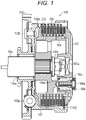
- Fig. 1 is a sectional view showing the outline of an entire configuration of a multiplate clutch device 100 including friction plates 200 as joint components according to the present invention.
- Fig. 2 is a plan view showing the outline of an external configuration of the friction plate 200 included in the multiplate clutch device 100 shown in Fig. 1 .
- Fig. 3 is a partially-enlarged side view schematically showing a sectional view of the friction plate 200 along a 3-3 line shown in Fig. 2 .
- the multiplate clutch device 100 is a mechanical device for transmitting drive force of an engine (not shown) as a motor in a two-wheeled vehicle (a motorcycle) to a wheel (not shown) as a drive target or blocking such force transmission.
- the multiplate clutch device 100 is arranged between the engine and a transmission (not shown).
- the multiplate clutch device 100 includes a housing 101 made of aluminum alloy.
- the housing 101 is a member formed in a bottomed cylindrical shape and forming part of a housing of the multiplate clutch device 100.
- An input gear 102 is, with a rivet 102b, fixed to the left side surface of the housing 101 as viewed in the figure through a torque damper 102a.
- the input gear 102 is rotatably driven with the input gear 102 engaging with a not-shown drive gear which is rotatably driven by drive of the engine.
- On an inner peripheral surface of the housing 101 multiple (eight in the present embodiment) clutch plates 103 are held by spline fitting so as to displace along an axial direction of the housing 101 and rotate integrally with the housing 101.
- the clutch plate 103 is an annular flat plate-shaped component to be pressed against the later-described friction plate 200.
- the clutch plate 103 is formed in such a manner that a thin plate member made of a steel plate cold commercial (SPCC) material is punched into an annular shape.
- SPCC steel plate cold commercial
- Not-shown oil grooves having depths of several ⁇ m to several tens of ⁇ m for holding later-described lubricant oil are formed at both side surfaces (front and back surfaces) of each clutch plate 103.
- surface hardening treatment is performed for both side surfaces (the front and back surfaces) of each clutch plate 103 formed with the oil grooves. Note that such surface hardening treatment does not directly relate to the present invention, and for this reason, description thereof will be omitted.
- a friction plate holder 104 formed in a substantially cylindrical shape is arranged concentrically with the housing 101. Many spline grooves are formed along an axial direction of the friction plate holder 104 at an inner peripheral surface of the friction plate holder 104.
- a shaft 105 is spline-fitted in these spline grooves.
- the shaft 105 is a shaft body formed in a hollow shape. One (the right side as viewed in the figure) end side of the shaft 105 rotatably supports the input gear 102 and the housing 101 through a needle bearing 105a, and supports the spline-fitted friction plate holder 104 in a fixed manner through a nut 105b.
- the friction plate holder 104 rotates integrally with the shaft 105.
- the other (the left side as viewed in the figure) end side (not shown) of the shaft 105 is coupled to the not-shown transmission of the two-wheeled vehicle.
- a shaft-shaped push rod 106 is arranged to penetrate a hollow portion of the shaft 105 with the push rod 106 protruding from the above-described one (the right side as viewed in the figure) end portion of the shaft 105.
- a side (the left side as viewed in the figure) opposite to the end portion protruding from the one (the right side as viewed in the figure) end portion of the shaft 105 is coupled to a not-shown clutch operation lever of the two-wheeled vehicle.
- the push rod 106 slides along an axial direction of the shaft 105 in the hollow portion of the shaft 105 by operation of the clutch operation lever.
- the multiple (seven in the present embodiment) friction plates 200 are held by spline fitting so as to displace along the axial direction of the friction plate holder 104 and rotate integrally with the friction plate holder 104 with each clutch plate 103 being sandwiched between adjacent ones of the friction plates 200.
- the inside of the friction plate holder 104 is filled with a predetermined amount of lubricant oil (not shown), and three tubular support rods 104a are formed in the friction plate holder 104 (the figure shows only one tubular support rod 104a).
- the lubricant oil is supplied to among the friction plates 200 and the clutch plates 103, thereby absorbing friction heat generated among the friction plates 200 and the clutch plates 103 and preventing abrasion of friction members 207.
- Each of the three tubular support rods 104a is formed so as to protrude outwardly (the right side as viewed in the figure) in the axial direction of the friction plate holder 104.
- a pressing cover 107 arranged at a position concentric with the friction plate holder 104 is assembled through a bolt 108a, a receiving plate 108b, and a coil spring 108c.
- the pressing cover 107 is formed in a substantially discoid shape having the substantially same outer diameter as the outer diameter of the friction plate 200.
- the pressing cover 107 is pressed to a friction plate holder 104 side by the coil spring 108c.
- a release bearing 107a is provided at a position facing the right tip end portion of the push rod 106 as viewed in the figure.
- the friction plate 200 includes each of oil grooves 205 and the friction members 207 on an annular flat plate-shaped core 201.
- the core 201 is a member forming a base portion of the friction plate 200.
- the core 201 is formed in such a manner that a thin plate member made of a steel plate cold commercial (SPCC) material is punched into a substantially annular shape.
- SPCC steel plate cold commercial
- an internal gear-shaped spline 202 to be spline-fitted onto the friction plate holder 104 is formed at an inner peripheral portion of the core 201.
- the friction members 207 are provided along a peripheral direction of the core 201 on a joint surface 203 through fine recessed portions 204 and a cover layer 206.
- the joint surface 203 is a portion to which the friction members 207 are joined, and is formed as a flat surface.
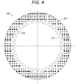
- the joint surface 203 is, as indicated by a hatched portion in Fig. 4 , formed in a circular ring shape outside the spline 202 in a radial direction at the plate surface of the core 201.
- the joint surface 203 is formed with a slightly greater width than the width of the friction member 207 in the radial direction of the core 201.
- a portion formed with no small piece-shaped friction members 207 among the friction members 207 also forms the joint surface 203. That is, the joint surface 203 is formed with a slightly greater width than the width of the friction member 207 in the radial direction of the core 201 in a circular ring shape continuously extending along the peripheral direction of the core 201.
- the joint surface 203 is formed at each surface of the core 201, and is formed as a flat surface with a flatness of equal to or less than 0.15 mm.
- the flatness described herein is the degree of distortion of a planar shape from a geometrically-accurate flat surface, and is represented by a clearance between two parallel imaginary planes when the clearance between these two imaginary planes is minimum in a case where a surface as a measurement target is sandwiched between the two imaginary planes.
- the flatness can be measured by, e.g., a dial gauge, an optical flat (a plane gauge), or a measuring instrument using laser light.
- the joint surface 203 may be formed with the same width as the width of the friction member 207 in the radial direction of the core 201, needless to say.
- the joint surface 203 may be formed only by a portion of the plate surface of the core 201 to which the friction members 207 are joined, i.e., a portion to which the friction members 207 are actually joined other than a portion formed with no small piece-shaped friction members 207 among the friction members 207.
- the core 201 is formed with such flat surfaces that the flatness of the entirety of each surface including the joint surface 203 is equal to or less than 0.15 mm. Since the joint surface 203 is not clearly visible, the joint surface 203 is purposely hatched in Fig. 4 , but is not shown in Figs. 2, 3 , and 7 .
- the fine recessed portion 204 is a portion for improving joint force of the friction member 207 joined onto the joint surface 203.
- the fine recessed portion 204 is formed in a shape recessed from the joint surface 203.
- the fine recessed portion 204 opens with an extremely-small size at the joint surface 203.
- the fine recessed portion 204 opens with such a size that the fine recessed portion 204 is within a circle with a diameter of 40 ⁇ m to 120 ⁇ m.
- the fine recessed portion 204 opens in the shape of a circle with a diameter of 80 ⁇ m as viewed in plane.
- the fine recessed portion 204 includes a bottomed hole.
- the fine recessed portion 204 is formed in such a spherical shape that a deepest portion of a bottom portion has a depth of 10 ⁇ m. Note that the fine recessed portion 204 may be formed so as to penetrate the core 201.
- the fine recessed portions 204 are formed such that adjacent ones of the fine recessed portions 204 at the joint surface 203 do not overlap with each other and a formation density per unit area Ua at the joint surface 203 is uniform.
- the "uniform formation density” does not mean that a certain number of fine recessed portions 204 is precisely formed at any position at the joint surface 203, but means that the number of fine recessed portions 204 is substantially uniform across the joint surface 203, needless to say.
- the uniform formation density means a density within a range of ⁇ 10%.
- about 100 fine recessed portions 204 are formed within a square region of 1 mm 2 as viewed in plane.
- the percentage of the total area of the fine recessed portions 204 in the unit area Ua as viewed in plane is about 50%.
- the unit area Ua is a virtual region set for the joint surface 203.
- the fine recessed portions 204 are arrayed in a spiral shape along the peripheral direction of the core 201. In this case, the fine recessed portions 204 are formed at equal intervals along a spiral direction.
- the fine recessed portions 204 are formed as laser processing marks remaining after part of the surface of the core 201 has been removed in a recessed shape by laser light irradiation. Note that Fig. 2 and Figs. 3 and 7 described later exaggeratingly show the fine recessed portions 204.
- the oil groove 205 is not only a flow path for guiding the lubricant oil between an inner peripheral edge and an outer peripheral edge of the core 201 of the friction plate 200, but also an oil holding portion for holding the lubricant oil between the friction plate 200 and the clutch plate 103.
- the oil groove 205 is formed as a clearance between adjacent ones of the friction members 207.
- the oil grooves 205 include a fan-shaped portion between adjacent groups of three small piece-shaped friction members 207 and a linear portion between adjacent ones of three friction members 207 arranged between adjacent two of the fan-shaped oil grooves 205.
- the cover layer 206 is a portion covering the fine recessed portions 204 formed at a portion of the core 201 provided with no friction members 207.
- the cover layer 206 is made of a thermosetting resin adhesive, and is formed with a substantially uniform thickness across the entirety of each surface of the core 201.
- the cover layer 206 is also formed on each side surface of the spline 202.
- the cover layer 206 is formed with such a thickness that at least the depth of the fine recessed portion 204 is decreased by application of the cover layer 206.
- the cover layer 206 preferably has a thickness of equal to or greater than 1 ⁇ m and equal to or less than 30 ⁇ m and more preferably equal to or greater than 5 ⁇ m and equal to or less than 20 ⁇ m.
- the cover layer 206 is formed with a thickness of 6 ⁇ m from the surface of the core 201.
- the cover layer 206 is formed transparent or translucent to such an extent that a person can visually recognize the surface of the core 201.
- thermosetting resin forming the cover layer 206 phenol resin, modified phenol resin, epoxy resin, urea resin, unsaturated polyester resin, polyurethane resin, or polyimide resin may be used.
- the cover layer 206 is made of phenol resin.
- various elastomers e.g., nitrile rubber-based elastomer or chloroprene rubber-based elastomer
- the resin forming the cover layer 206 does not necessarily have adhesion properties.
- the cover layer 206 is made of such resin that at least the depth of the fine recessed portion 204 can be decreased by application of the resin.
- an adhesive made of a substance different from the resin forming the cover layer 206 may be used as a material for fixing the friction member 207 onto the core 201.
- the friction member 207 improves friction force against the clutch plate 103.
- the friction member 207 is made of a small piece-shaped paper material bonded along the peripheral direction of the core 201.
- the friction members 207 are formed such that eight small piece groups are arranged in the peripheral direction of the core 201 through eight fan-shaped oil grooves 205. In each small piece group, three rectangular small pieces extending in the peripheral direction of the core 201 are arranged in the peripheral direction of the core 201 through three linear oil grooves 205.
- the friction member 207 is made of a material capable of improving the friction force between the friction plate 200 and the clutch plate 103.
- the friction member 207 may be made of a material other than the paper material, such as a cork material, a rubber material, or a glass material. Note that in Fig. 2 , the friction members 207 are illustrated as darker-shaded areas.
- a worker prepares, as a first step, each of the core 201 and the friction members 207. Specifically, as shown in Fig. 4 , the worker forms, by pressing performed separately, the core 201 into a circular ring shape having the spline 202.
- Such pressing is the well-known processing technique of punching a metal (e.g., a SPCC material) thin plate member as the material of the core 201 into a circular ring shape by means of a die.
- the worker uses a plate member with a flatness of equal to or less than 0.15 mm as the metal thin plate member which is the material of the core 201.
- the worker can obtain the flat plate-shaped core 201 having the flat joint surfaces 203 with a flatness of equal to or less than 0.15 mm. That is, the step of preparing the core 201 at the first step is equivalent to a base body preparation step according to the present invention.
- the friction members 207 are formed in a band shape by papermaking performed separately. Papermaking for the friction members 207 is a typical well-known technique, and therefore, description thereof will be omitted.
- the worker forms, as a second step, the fine recessed portions 204 at each surface of the core 201.
- the worker forms, as shown in Fig. 6 , the fine recessed portions 204 by means of a laser processing device 300.
- the laser processing device 300 described herein is a mechanical device for forming the fine recessed portions 204 by irradiation of the core 201 with laser light L.
- the laser processing device 300 is a well-known mechanical device, and detailed description thereof will be omitted. Note that the configuration thereof will be briefly described.
- the laser processing device 300 mainly includes each of a laser oscillator (not shown), a laser adjustment optical system (not shown), a laser head 301, a work table 302, and a control device (not shown).
- the laser oscillator is a mechanical device for emitting the laser light L for removing the surface of the core 201 in a recessed shape and forming the fine recessed portions 204 accordingly.
- the laser oscillator is an oscillator having a frequency of 300 kHz and an output power of 60 W and configured to oscillate pulse laser light with a short pulse width such as a pulse width of nanoseconds, picoseconds, or femtoseconds.
- the laser adjustment optical system includes an optical component including various optical elements such as a lens and a mirror, an optical fiber, and the like, and the optical component guides the laser light L, emitted from the laser oscillator, to the laser head 301 while performing various types of adjustment such as correction of a beam diameter, a beam shape, and an aberration.
- an optical component including various optical elements such as a lens and a mirror, an optical fiber, and the like, and the optical component guides the laser light L, emitted from the laser oscillator, to the laser head 301 while performing various types of adjustment such as correction of a beam diameter, a beam shape, and an aberration.
- the laser head 301 is an optical device configured to emit the laser light L, which has been guided from the laser adjustment optical system, toward the work table 302 to collect the laser light L onto the core 201.
- the laser head 301 is configured displaceable in three axial directions of an X-axis direction, a Y-axis direction, and a Z-axis direction perpendicular to each other relative to the work table 302.
- the work table 302 is a device detachably holding the core 201, to which the friction members 207 are bonded, at a position facing the laser head 301. Note that the laser head 301 and the work table 302 are in a relative positional relationship. Thus, a configuration in which the work table 302 is displaceable instead of the laser head 301 may be employed, needless to say.
- the control device includes a microcomputer having a CPU, a ROM, a RAM, and the like, and controls actuation of the entirety of the laser processing device 300 in an integrated manner. Specifically, the control device controls, according to a worker's instruction, actuation of each of the laser oscillator, the laser adjustment optical system, and the laser head 301 to displace the laser light L onto the core 201 during irradiation, thereby forming the fine recessed portions 204.
- the worker holds the core 201 on the work table 302. Thereafter, the worker instructs the control device of the laser processing device 300 to process the fine recessed portions 204. In response to such an instruction, the control device displaces the laser head 301 in the X-axis direction and the Y-axis direction while the laser light L is being emitted from the laser head 301, thereby displacing the laser light L on the core 201 to form the fine recessed portions 204.
- the control device starts, as shown in Fig. 7 , irradiating an innermost peripheral portion of the joint surface 203 of the core 201 with the laser light L.
- the control device displaces the laser head 301 in a spiral pattern extending gradually outwardly in the radial direction, and when the laser head 301 reaches a position P 2 of an outermost peripheral portion of the joint surface 203, stops emission of the laser light L.
- many fine recessed portions 204 are formed in the spiral shape along the peripheral direction at the joint surface 203 of the core 201.
- each fine recessed portion 204 is formed by one processing mark formed by a single pulse of laser light L emitted from the laser head 301.
- One fine recessed portion 204 may be formed by multiple processing marks (i.e., two or more pulses of laser light L). Note that in Fig. 7 , the circular path of displacement of the laser light L is indicated by a dashed line.
- the worker takes the core 201 from the work table 302. Accordingly, the process of forming the fine recessed portions 204 on one side of the core 201 ends. Thus, the worker turns over the core 201 formed with the fine recessed portions 204, and performs a similar process for another surface to form the fine recessed portions 204. In this manner, the worker can form the fine recessed portions 204 at each joint surface 203 of the core 201. That is, the second step is equivalent to a fine recessed portion formation step according to the present invention.
- the worker forms, as a third step, the cover layer 206 on each of the two plate surfaces of the core 201.
- the worker heats and dries, as shown in Fig. 3 , a resin layer raw material containing liquid thermosetting resin as the raw material of the cover layer 206 after the resin layer raw material has been applied to the entirety of each of the two plate surfaces of the core 201 by means of a tool such as a brush or a roller.
- a tool such as a brush or a roller.
- the cover layer 206 made of the hardened resin layer raw material can be formed.
- the worker coats the surface of the core 201 once or overcoats the surface of the core 201 multiple times, thereby forming the cover layer 206.
- the third step is equivalent to a cover layer formation step according to the present invention.
- the worker bonds, as a fourth step, the friction members 207 to each of the two plate surfaces of the core 201.
- the worker applies a liquid adhesive (not shown) to the entirety of each of the two cover layers 206 on the core 201 by means of a tool such as a brush or a roller.
- the worker places the friction members 207 before the adhesive is dried, and then, dries the adhesive.
- a resin layer raw material containing the same liquid thermosetting resin as the raw material of the cover layer 206 is used as the adhesive. That is, the resin raw material forming the cover layer 206 is made of the adhesive.
- the worker may cut, after the friction members 207 have been placed on the core 201, the band-shaped friction members 207 placed on the core 201, thereby forming the friction members 207 into the small piece shape.
- the worker may place the friction members 207, which are formed in the small piece shape in advance, on the core 201. In this manner, the friction members 207 are fixed onto the cover layers 206 on the core 201.
- the fourth step is equivalent to a joint object joining step according to the present invention.
- the worker may apply the adhesive only to positions at which the friction members 207 are to be arranged or only onto the circular ring-shaped joint surface 203.
- the worker may apply the adhesive to a friction member 207 side instead of or in addition to application of the adhesive to the core 201.
- the worker performs a friction property adjustment step and an inspection step, thereby completing the friction plate 200.
- the multiplate clutch device 100 is, as described above, arranged between the engine and the transmission in the vehicle, thereby transmitting the drive force of the engine to the transmission or block such force transmission according to operation of the clutch operation lever by a driver of the vehicle.
- the push rod 106 is brought into a state in which the tip end portion thereof does not press the release bearing 107a, and the pressing cover 107 presses the clutch plates 103 by elastic force of the coil spring 108c. Accordingly, the clutch plates 103 and the friction plates 200 are pressed against each other while displacing to a receiving portion 104b side, a receiving portion 104b being formed in a flange shape at the outer peripheral surface of the friction plate holder 104. Accordingly, the clutch plates 103 and the friction plates 200 are brought into a friction-coupled state. As a result, the drive force of the engine transmitted to the input gear 102 is transmitted to the transmission through the clutch plates 103, the friction plates 200, the friction plate holder 104, and the shaft 105.
- the friction plates 200 can transmit the rotary drive force to the clutch plates 103 with a favorable accuracy in a state in which the clutch plates 103 and the friction plates 200 friction-contact each other.
- the push rod 106 is brought into a state in which the tip end portion thereof presses the release bearing 107a, and the pressing cover 107 displaces to the right side as viewed in the figure against the elastic force of the coil spring 108c to separate from and the clutch plates 103. Accordingly, the clutch plates 103 and the friction plates 200 displace to a pressing cover 107 side, and a state in which these plates are pressed against and coupled to each other is cancelled. Thus, the clutch plates 103 and the friction plates 200 are separated from each other. As a result, the drive force is no longer transmitted from the clutch plates 103 to the friction plates 200, and transmission of the drive force, which has been transmitted to the input gear 102, of the engine to the transmission is blocked.
- the friction members 207 are also firmly joined to the core 201 through the fine recessed portions 204 at the friction plates 200.
- the fine recessed portions 204 formed at a portion of the joint surface 203 of the core 201 provided with no friction members 207, such as the oil groove 205, are covered with the adhesive for the friction member 207.
- the multiplate clutch device 100 including the friction plates 200 as the joint components, many fine recessed portions 204 formed at the joint surfaces 203 of the metal core 201 as a target to which the friction members 207 as joint objects are joined are formed not to overlap with each other and to have the uniform formation density per unit area Ua.
- the flatness of the joint surface 203 can be equal to or less than 0.15 mm.
- the fine recessed portion 204 is formed so as to open in the shape of the circle with a diameter of 80 ⁇ m as viewed in plane. However, it may only be required that the fine recessed portion 204 is formed so as to open with such a size that the fine recessed portion 204 is within the circle with a diameter of 40 ⁇ m to 120 ⁇ m. Thus, the fine recessed portion 204 may be formed in a shape other than the circular or oval shape, such as a quadrangular or triangular shape.
- the fine recessed portion 204 is formed in such a spherical shape that the deepest portion of the bottom portion has a depth of 10 ⁇ m.
- the fine recessed portion 204 may be formed such that the depth from the joint surface 203 to the bottom portion may be less than 10 ⁇ m or equal to or greater than 10 ⁇ m.
- the bottom portion may be formed in a shape other than the spherical shape, such as a quadrangular or pyramid shape.
- the depth of the fine recessed portion 204 is preferably equal to or greater than 5 ⁇ m and equal to or less than 20 ⁇ m and more preferably equal to or less than 10 ⁇ m.
- the fine recessed portions 204 are formed such that the total opening area as viewed in plane is 50% with respect to the unit area Ua. However, it may only be required that the fine recessed portions 204 are formed such that at least the formation density per unit area Ua is uniform at any position in a region formed with the fine recessed portions 204. Thus, the fine recessed portions 204 may be formed such that the total opening area as viewed in plane is less than 50% or exceeds 50% with respect to the unit area Ua. In this case, the fine recessed portions 204 are preferably formed such that the total opening area as viewed in plane is equal to or greater than 40% and equal to or less than 80% with respect to the unit area Ua.
- the fine recessed portions 204 are formed such that adjacent ones of the fine recessed portions 204 do not overlap with each other, i.e., are separated from each other. Note that the fine recessed portions 204 may be formed such that adjacent ones of the fine recessed portions 204 contact each other.
- the fine recessed portions 204 are formed so as to be arrayed in the spiral shape along the peripheral direction of the core 201. However, it may only be required that the fine recessed portions 204 are formed such that adjacent ones of the fine recessed portions 204 do not overlap with each other and the formation density per unit area Ua smaller than the area of the joint surface is uniform. Thus, as shown in, e.g., Fig. 8 , the fine recessed portions 204 may be formed so as to be arranged linearly along each of two directions (the right-left and upper-lower directions as viewed in the figure) perpendicular to each other at the center of the core 201. Alternatively, as shown in, e.g., Fig.
- the fine recessed portions 204 may be formed such that a certain line of the fine recessed portions 204 arranged linearly in the right-left direction as viewed in the figure is arranged so as to be shifted from an adjacent line of the fine recessed portions 204 in an arrangement direction.
- the fine recessed portions 204 may be formed such that a distance between adjacent ones of the fine recessed portions 204 is uniform.
- the fine recessed portions 204 may be formed such that adjacent ones of the fine recessed portions 204 are arranged in an annular shape.
- the fine recessed portions 204 may be formed so as to be arranged in a radial or circular ring shape. Note that Figs. 8 to 11 show only some of many fine recessed portions 204 formed at the joint surface 203.
- the fine recessed portions 204 are processed using the pulse laser light L.
- the fine recessed portions 204 may be formed using a processing method other than laser processing.
- the fine recessed portions 204 may be also formed by discharging.
- the fine recessed portions 204 may be processing marks other than the processing marks formed by the laser light.
- the joint surface 203 of the core 201 is formed such that the flatness thereof is equal to or less than 0.15 mm. However, it may only be required that the joint surface 203 is formed such that the flatness thereof is equal to or less than at least 0.2 mm. Thus, the joint surface 203 may be formed such that the flatness thereof is equal to or greater than 0.15 mm and equal to or less than 0.2 mm or the flatness thereof is less than 0.15 mm. Alternatively, the joint surface 203 may be formed only on one side of the core 201. That is, the fine recessed portions 204 may be formed only on one side of the core 201.
- the cover layer 206 is formed across the entirety of each surface of the core 201. However, it may only be required that the cover layer 206 is formed at least on the fine recessed portions 204 on which no friction members 207 are arranged. In this case, the fine recessed portions 204 may be filled with the cover layer 206, and the cover layer 206 may be formed in a layer shape on the surface of the core 201. Alternatively, part or the entirety of the fine recessed portions 204 may be filled with the cover layer 206, and the cover layer 206 is not necessarily formed on the surface of the core 201.
- the friction plate 200 is formed such that the fine recessed portions 204 are covered with the cover layers 206.
- the friction plate 200 may be formed without the cover layers 206. That is, the cover layer formation step may be omitted from the steps of manufacturing the friction plate.
- the cover layer 206 is made of the resin material having the adhesion properties for the friction member 207.
- the cover layer 206 does not necessarily have the adhesion properties, and may be made of a resin material having no adhesion properties for the friction member 207.
- the cover layer 206 may be formed opaque.
- the friction members 207 are provided in such a manner that the multiple small pieces are discontinuously arranged along the peripheral direction of the core 201 through the clearances forming the oil grooves 205.
- the friction members 207 are provided as necessary according to the specifications of the multiplate clutch device 100.
- the friction member 207 may be formed in a circular ring shape continuously extending in the peripheral direction of the core 201. That is, the friction plate 200 may be formed without the oil grooves 205.
- the friction plates 200 are held by the friction plate holder 104 to be rotatably driven integrally with the shaft 105. That is, the friction plate 200 is applied as an opposing plate, and the opposing plate is arranged facing the clutch plate 103 to be rotatably driven by the rotary drive force of the engine and is rotatably driven integrally with the shaft 105 as an output shaft in the multiplate clutch device 100.
- the friction plate 200 may be also applied to the clutch plate 103 as a drive-side plate to be rotatably driven by the rotary drive force of the engine.
- the laser processing device 300 is configured to displace the laser head 301 in the three axial directions of the X-axis direction, the Y-axis direction, and the Z-axis direction perpendicular to each other.
- the laser processing device 300 may include, for example, a galvanoscanner or a polygon mirror in the laser head 301 to scan the laser light in each of the X-axis direction and the Y-axis direction instead of or in addition to displacement of the laser head 301 and/or the work table 302.
- the laser processing device 300 may be configured such that the core 201 to which the friction members 207 are bonded is held on the work table 302 configured movable or fixed and the core 201 is rotatably driven on the work table 302 or is scanned in each of the X-axis direction and the Y-axis direction.
- the friction plate 200 is applied to the wet multiplate clutch device 100 to be rotatably driven in the lubricant oil.
- the friction plate 200 may be also applied to a dry multiplate clutch device 100 using no lubricant oil.
- the friction plate 200 may be also applied as a friction plate used for a clutch device (not shown) provided in a torque converter configured to amplify drive force from an engine to an output shaft side to transmit such force.
- the friction plate 200 may be also applied to a friction plate used for a brake device (not shown) configured to put a brake on rotary motion by a motor.
- the present invention can be broadly applied to a joint component configured such that a joint object is joined to a planar joint surface formed at a metal base body.
- a metal material forming the base body includes non-ferrous metal such as an aluminum material, a steel material such as stainless steel, and various alloy materials.
- the joint object may be made of a metal material or a material other than the metal material, such as rubber, elastomer, resin, or ceramic.
- the joint component includes, for example, a water pump, a cylinder head, an oil pan, and an exterior component of an electronic equipment.
Landscapes
- Engineering & Computer Science (AREA)
- General Engineering & Computer Science (AREA)
- Mechanical Engineering (AREA)
- Physics & Mathematics (AREA)
- Optics & Photonics (AREA)
- Plasma & Fusion (AREA)
- Mechanical Operated Clutches (AREA)
- Braking Arrangements (AREA)
- Laser Beam Processing (AREA)
Abstract
Description
- The present invention relates to a joint component configured such that a joint object is joined to a planar joint surface formed at a metal base body, a multiplate clutch device including the joint component, and a joint component manufacturing method.
- Typically, a vehicle such as a four-wheeled vehicle or a two-wheeled vehicle has been equipped with a multiplate clutch device for transmitting rotary drive force of a motor such as an engine to a drive target such as a wheel or blocking such force transmission. Generally, in the multiplate clutch device, two plates, i.e., a drive-side plate and a driven-side plate, arranged facing each other are pressed against or separated from each other in lubricant oil, and in this manner, the rotary drive force is transmitted or blocked.
- In this case, one of these two plates is a wet friction plate configured such that friction members are provided along a peripheral direction on a surface of an annular flat plate-shaped core. For example, at a clutch plate disclosed in Patent Literature 1 below, many recesses are formed at each side surface of a core plate as a core formed in an annular flat plate shape for the purpose of improving the adhesion strength of a facing as a friction member.
- PATENT LITERATURE 1:
JP-A-9-324824 - However, at the clutch plate described in Patent Literature 1 above, many recesses are formed by sandblasting. For this reason, there is a problem that the flatness of the core is degraded due to, e.g., an uneven density of collision of sand grains with the core, an uneven strength of such collision, and uneven formation of the recesses between both side surfaces of the core.
- The present invention has been made for coping with the above-described problem. An object of the present invention is to provide a joint component formed with fine recessed portions so that degradation of the flatness of a metal base body, such as a core, to which a joint object such as a friction member is joined can be reduced, a multiplate clutch device including the joint component, and a joint component manufacturing method.
- In order to achieve the above object, as a feature of the present invention, there is provided a joint component including: a metal base body having a joint surface formed as a flat surface; and a joint obj ect to be joined to the j oint surface. The j oint surface has a flatness of equal to or less than 0.2 mm, and is formed with many fine recessed portions formed in a recessed shape. The fine recessed portions are formed such that adjacent ones of the fine recessed portions do not overlap with each other and a formation density per unit area smaller than an area of the joint surface is uniform.
- According to the feature of the present invention configured as described above, in the joint component, many fine recessed portions formed at the joint surface of the metal base body as a target to which the joint object is to be joined are formed not to overlap with each other and to have the uniform formation density per unit area. With this configuration, the flatness of the joint surface can be equal to or less than 0.2 mm. Note that the fine recessed portion is a bottomed hole or a through-hole opening at the joint surface with such a size that the fine recessed portion is within a circle with a diameter of 40 µm to 120 µm. Moreover, the unit area is the area of a square region as viewed in plane at the joint surface, and for example, is 1 mm2 or 1 cm2.
- Note that Patent Literature 1 above describes, with reference to
Figs. 3 and6 , a state in which adjacent ones of the recesses are formed not to overlap with each other at the core plate. However, the recesses in Patent Literature 1 above are formed by sandblasting. For this reason, it is impossible that the recesses are formed not to overlap with each other. That is,Figs. 3 and6 in Patent Literature 1 above are schematically shown for the sake of understanding of the recesses formed at the core plate, and do not intended to disclose the invention of the present application. - Moreover, as another feature of the present invention, in the joint component, the fine recessed portions are formed such that a total opening area as viewed in plane in the unit area is equal to or greater than 40% and equal to or less than 80% with respect to the unit area.
- According to another feature of the present invention configured as described above, in the joint component, the total opening area of the fine recessed portions as viewed in plane in the unit area is equal to or greater than 40% and equal to or less than 80% with respect to the unit area. With this configuration, the fine recessed portions can be easily formed not to overlap with each other and to have the uniform formation density per unit area.
- Moreover, as another feature of the present invention, in the joint component, the fine recessed portions are formed such that a distance between adjacent ones of the fine recessed portions is uniform.
- According to another feature of the present invention configured as described above, in the joint component, the distance between adjacent ones of the fine recessed portions is uniform. With this configuration, the fine recessed portions can be easily formed not to overlap with each other and to have the uniform formation density per unit area.
- Moreover, as another feature of the present invention, in the joint component, the fine recessed portions are processing marks formed by laser light.
- According to another feature of the present invention configured as described above, in the joint component, the fine recessed portions are the processing marks formed by laser light. With this configuration, the fine recessed portions can be easily formed not to overlap with each other and to have the uniform formation density per unit area. Moreover, since residual stress on the joint surface is less in laser processing than in sandblasting, degradation of the flatness of the joint surface can be reduced.
- Moreover, as another feature of the present invention, in the joint component, the joint surface is formed in a circular or circular ring shape as viewed in plane, and the fine recessed portions are formed to be arranged in a spiral shape in a peripheral direction of the joint surface.
- According to another feature of the present invention configured as described above, in the joint component, the joint surface is formed in the circular or circular ring shape as viewed in plane, and the fine recessed portions are formed so as to be arranged in the spiral shape in the peripheral direction of the joint surface. With this configuration, the fine recessed portions can be easily formed not to overlap with each other and to have the uniform formation density per unit area.
- Moreover, as another feature of the present invention, in the joint component, the base body includes a core formed in an annular flat plate shape, the joint object includes a friction member bonded to a surface of the core along the peripheral direction, and the joint component includes friction plates arranged facing each other in a clutch device or a brake device and configured to closely contact or separate from each other to transmit or block rotary drive force between the friction plates.
- According to another feature of the present invention configured as described above, in the joint component, the base body includes the core formed in the annular flat plate shape, and the joint object includes the friction member bonded to the surface of the core along the peripheral direction. With this configuration, the joint components can be formed as the friction plates arranged facing each other in the clutch device or the brake device and configured to closely contact or separate from each other to transmit or block the rotary drive force therebetween. That is, the invention of the present application can be also implemented as an invention relating to the friction plates arranged facing each other in the clutch device or the brake device and configured to closely contact or separate from each other to transmit or block the rotary drive force therebetween.
- Moreover, as another feature of the present invention, in the joint component, a depth of each of the fine recessed portions from the joint surface is equal to or less than 10 µm.
- According to another feature of the present invention configured as described above, in the joint component as the friction plate, the fine recessed portions are formed such that the depth of each fine recessed portion from the joint surface is equal to or less than 10 µm. With this configuration, degradation of the flatness of the thin friction plate can be effectively reduced.
- Moreover, as another feature of the present invention, in the joint component, the fine recessed portions are formed only in a region, where the friction member is arranged, in a circular ring shape in the peripheral direction at the core.
- According to another feature of the present invention configured as described above, in the joint component as the friction plate, the fine recessed portions are formed only in the region, where the friction member is arranged, in the circular ring shape in the peripheral direction at the core. With this configuration, the fine recessed portions can be efficiently formed, and degradation of the flatness of the thin friction plate can be effectively reduced.
- Moreover, as another feature of the present invention, in the joint component, the fine recessed portions are also formed at a portion of the base body other than a portion to which the joint object is joined, and the base body includes a cover layer covering the fine recessed portions formed at the portion other than the portion to which the joint object is joined.
- According to another feature of the present invention configured as described above, the joint component includes the cover layer covering the fine recessed portions formed at the portion of the base body other than the portion to which the joint object is joined. Since the fine recessed portions formed at the portion other than the portion to which the joint object is joined are covered, influence due to the fine recessed portions, specifically, e.g., degradation of the flowability of lubricant oil due to the fine recessed portions exposed through the core, can be reduced.
- The present invention can be implemented not only as the invention relating to the joint component, but also as an invention relating to a multiplate clutch device including the joint component and an invention relating to a joint component manufacturing method.
- Specifically, in the multiplate clutch device for transmitting or blocking rotary drive force between a drive-side plate to be rotatably driven by a motor and a driven-side plate arranged facing the drive-side plate through a clearance in such a manner that the drive-side plate and the driven-side plate closely contact or separate from each other, at least one of the drive-side plate or the driven-side plate may be the friction plate as the joint component provided in the clutch device according to any one of claims 6 to 9. According to this configuration, features and advantageous effects similar to those of the above-described joint component can be expected from the multiplate clutch device.
- Moreover, regarding the joint component manufacturing method for manufacturing a joint component configured such that a joint object is joined to a joint surface as a flat surface formed at a metal base body, the method may include: a base body preparation step of preparing the base body having the joint surface with a flatness of equal to or less than 0.2 mm; a fine recessed portion formation step of forming many fine recessed portions at least at the joint surface by irradiating the base body with laser light while relatively displacing the laser light; and a joint object joining step of joining the joint object to the joint surface. At the fine recessed portion formation step, the fine recessed portions may be formed in such arrangement that adjacent ones of the fine recessed portions do not overlap with each other and a formation density per unit area smaller than an area of the joint surface is uniform.
- In this case, the above joint component manufacturing method may further include a cover layer formation step of forming a cover layer covering the fine recessed portions.
- Moreover, in the cases above, in the joint component manufacturing method, the joint surface may be formed in a circular or circular ring shape, and at the fine recessed portion formation step, the fine recessed portions may be formed to extend in a spiral shape along a peripheral direction of the joint surface. According to this joint component manufacturing method, features and advantageous effects similar to those of the above-described joint component can be expected.
-
-
Fig. 1 is a sectional view showing an entire configuration of a multiplate clutch device including friction plates according to the present invention; -
Fig. 2 is a plan view showing the outline of an external configuration of the friction plate according to the present invention, the friction plate being assembled into the multiplate clutch device shown inFig. 1 ; -
Fig. 3 is a partially-enlarged side view of the friction plate schematically showing the sectional shape of the friction plate along a 3-3 line shown inFig. 2 ; -
Fig. 4 is a plan view showing the outline of an external configuration of a core forming the friction plate shown inFig. 2 ; -
Fig. 5 is a flowchart showing the steps of manufacturing the friction plate according to the present invention; -
Fig. 6 is a side view schematically showing the outline of the configuration of a laser processing device used at a fine recessed portion formation step at the steps of manufacturing the friction plate as shown inFig. 5 ; -
Fig. 7 is a plan view schematically showing a state in which fine recessed portions are formed at the core shown inFig. 4 ; -
Fig. 8 is a partial view for describing one variation of a fine recessed portion formation pattern according to a modification of the present invention; -
Fig. 9 is a partial view for describing one variation of the fine recessed portion formation pattern according to another modification of the present invention; -
Fig. 10 is a partial view for describing one variation of the fine recessed portion formation pattern according to another modification of the present invention; and -
Fig. 11 is a partial view for describing one variation of the fine recessed portion formation pattern according to another modification of the present invention. - Hereinafter, one embodiment of a joint component, a multiplate clutch device including the joint component, and a friction plate manufacturing method according to the present invention will be described with reference to the drawings.
Fig. 1 is a sectional view showing the outline of an entire configuration of a multiplateclutch device 100 includingfriction plates 200 as joint components according to the present invention. Moreover,Fig. 2 is a plan view showing the outline of an external configuration of thefriction plate 200 included in the multiplateclutch device 100 shown inFig. 1 . Further,Fig. 3 is a partially-enlarged side view schematically showing a sectional view of thefriction plate 200 along a 3-3 line shown inFig. 2 . Note that each figure as a reference in the present specification is schematically shown for the sake of easy understanding of the present invention and, e.g., some components are exaggeratingly shown. For this reason, the dimensions, ratios, etc. of the components may vary. The multiplateclutch device 100 is a mechanical device for transmitting drive force of an engine (not shown) as a motor in a two-wheeled vehicle (a motorcycle) to a wheel (not shown) as a drive target or blocking such force transmission. The multiplateclutch device 100 is arranged between the engine and a transmission (not shown). - The multiplate
clutch device 100 includes ahousing 101 made of aluminum alloy. Thehousing 101 is a member formed in a bottomed cylindrical shape and forming part of a housing of the multiplateclutch device 100. Aninput gear 102 is, with arivet 102b, fixed to the left side surface of thehousing 101 as viewed in the figure through atorque damper 102a. Theinput gear 102 is rotatably driven with theinput gear 102 engaging with a not-shown drive gear which is rotatably driven by drive of the engine. On an inner peripheral surface of thehousing 101, multiple (eight in the present embodiment)clutch plates 103 are held by spline fitting so as to displace along an axial direction of thehousing 101 and rotate integrally with thehousing 101. - The
clutch plate 103 is an annular flat plate-shaped component to be pressed against the later-describedfriction plate 200. Theclutch plate 103 is formed in such a manner that a thin plate member made of a steel plate cold commercial (SPCC) material is punched into an annular shape. Not-shown oil grooves having depths of several µm to several tens of µm for holding later-described lubricant oil are formed at both side surfaces (front and back surfaces) of eachclutch plate 103. Moreover, for the purpose of improving abrasion resistance, surface hardening treatment is performed for both side surfaces (the front and back surfaces) of eachclutch plate 103 formed with the oil grooves. Note that such surface hardening treatment does not directly relate to the present invention, and for this reason, description thereof will be omitted. - In the
housing 101, afriction plate holder 104 formed in a substantially cylindrical shape is arranged concentrically with thehousing 101. Many spline grooves are formed along an axial direction of thefriction plate holder 104 at an inner peripheral surface of thefriction plate holder 104. Ashaft 105 is spline-fitted in these spline grooves. Theshaft 105 is a shaft body formed in a hollow shape. One (the right side as viewed in the figure) end side of theshaft 105 rotatably supports theinput gear 102 and thehousing 101 through aneedle bearing 105a, and supports the spline-fittedfriction plate holder 104 in a fixed manner through anut 105b. That is, thefriction plate holder 104 rotates integrally with theshaft 105. On the other hand, the other (the left side as viewed in the figure) end side (not shown) of theshaft 105 is coupled to the not-shown transmission of the two-wheeled vehicle. - A shaft-shaped
push rod 106 is arranged to penetrate a hollow portion of theshaft 105 with thepush rod 106 protruding from the above-described one (the right side as viewed in the figure) end portion of theshaft 105. Of thepush rod 106, a side (the left side as viewed in the figure) opposite to the end portion protruding from the one (the right side as viewed in the figure) end portion of theshaft 105 is coupled to a not-shown clutch operation lever of the two-wheeled vehicle. Thepush rod 106 slides along an axial direction of theshaft 105 in the hollow portion of theshaft 105 by operation of the clutch operation lever. - On an outer peripheral surface of the
friction plate holder 104, the multiple (seven in the present embodiment)friction plates 200 are held by spline fitting so as to displace along the axial direction of thefriction plate holder 104 and rotate integrally with thefriction plate holder 104 with eachclutch plate 103 being sandwiched between adjacent ones of thefriction plates 200. - On the other hand, the inside of the
friction plate holder 104 is filled with a predetermined amount of lubricant oil (not shown), and threetubular support rods 104a are formed in the friction plate holder 104 (the figure shows only onetubular support rod 104a). The lubricant oil is supplied to among thefriction plates 200 and theclutch plates 103, thereby absorbing friction heat generated among thefriction plates 200 and theclutch plates 103 and preventing abrasion offriction members 207. - Each of the three
tubular support rods 104a is formed so as to protrude outwardly (the right side as viewed in the figure) in the axial direction of thefriction plate holder 104. Apressing cover 107 arranged at a position concentric with thefriction plate holder 104 is assembled through abolt 108a, a receivingplate 108b, and acoil spring 108c. Thepressing cover 107 is formed in a substantially discoid shape having the substantially same outer diameter as the outer diameter of thefriction plate 200. Thepressing cover 107 is pressed to afriction plate holder 104 side by thecoil spring 108c. At a center portion inside thepressing cover 107, arelease bearing 107a is provided at a position facing the right tip end portion of thepush rod 106 as viewed in the figure. - Specifically, as shown in each of
Figs. 2 and 3 , thefriction plate 200 includes each ofoil grooves 205 and thefriction members 207 on an annular flat plate-shapedcore 201. Thecore 201 is a member forming a base portion of thefriction plate 200. Thecore 201 is formed in such a manner that a thin plate member made of a steel plate cold commercial (SPCC) material is punched into a substantially annular shape. In this case, an internal gear-shapedspline 202 to be spline-fitted onto thefriction plate holder 104 is formed at an inner peripheral portion of thecore 201. - At a side surface of the
friction plate 200 facing theclutch plate 103, i.e., a circular ring-shaped plate surface of the core 201 facing theclutch plate 103, thefriction members 207 are provided along a peripheral direction of thecore 201 on ajoint surface 203 through fine recessedportions 204 and acover layer 206. - The
joint surface 203 is a portion to which thefriction members 207 are joined, and is formed as a flat surface. In the present embodiment, thejoint surface 203 is, as indicated by a hatched portion inFig. 4 , formed in a circular ring shape outside thespline 202 in a radial direction at the plate surface of thecore 201. In this case, thejoint surface 203 is formed with a slightly greater width than the width of thefriction member 207 in the radial direction of thecore 201. Further, a portion formed with no small piece-shapedfriction members 207 among thefriction members 207 also forms thejoint surface 203. That is, thejoint surface 203 is formed with a slightly greater width than the width of thefriction member 207 in the radial direction of the core 201 in a circular ring shape continuously extending along the peripheral direction of thecore 201. - The
joint surface 203 is formed at each surface of thecore 201, and is formed as a flat surface with a flatness of equal to or less than 0.15 mm. The flatness described herein is the degree of distortion of a planar shape from a geometrically-accurate flat surface, and is represented by a clearance between two parallel imaginary planes when the clearance between these two imaginary planes is minimum in a case where a surface as a measurement target is sandwiched between the two imaginary planes. The flatness can be measured by, e.g., a dial gauge, an optical flat (a plane gauge), or a measuring instrument using laser light. - Note that the
joint surface 203 may be formed with the same width as the width of thefriction member 207 in the radial direction of thecore 201, needless to say. Alternatively, thejoint surface 203 may be formed only by a portion of the plate surface of the core 201 to which thefriction members 207 are joined, i.e., a portion to which thefriction members 207 are actually joined other than a portion formed with no small piece-shapedfriction members 207 among thefriction members 207. In the present embodiment, thecore 201 is formed with such flat surfaces that the flatness of the entirety of each surface including thejoint surface 203 is equal to or less than 0.15 mm. Since thejoint surface 203 is not clearly visible, thejoint surface 203 is purposely hatched inFig. 4 , but is not shown inFigs. 2, 3 , and7 . - The fine recessed
portion 204 is a portion for improving joint force of thefriction member 207 joined onto thejoint surface 203. The fine recessedportion 204 is formed in a shape recessed from thejoint surface 203. In this case, the fine recessedportion 204 opens with an extremely-small size at thejoint surface 203. Specifically, the fine recessedportion 204 opens with such a size that the fine recessedportion 204 is within a circle with a diameter of 40 µm to 120 µm. In the present embodiment, the fine recessedportion 204 opens in the shape of a circle with a diameter of 80 µm as viewed in plane. - The fine recessed
portion 204 includes a bottomed hole. In the present embodiment, the fine recessedportion 204 is formed in such a spherical shape that a deepest portion of a bottom portion has a depth of 10 µm. Note that the fine recessedportion 204 may be formed so as to penetrate thecore 201. - The fine recessed
portions 204 are formed such that adjacent ones of the fine recessedportions 204 at thejoint surface 203 do not overlap with each other and a formation density per unit area Ua at thejoint surface 203 is uniform. In this case, the "uniform formation density" does not mean that a certain number of fine recessedportions 204 is precisely formed at any position at thejoint surface 203, but means that the number of fine recessedportions 204 is substantially uniform across thejoint surface 203, needless to say. Specifically, the uniform formation density means a density within a range of ±10%. In the present embodiment, about 100 fine recessedportions 204 are formed within a square region of 1 mm2 as viewed in plane. Thus, the percentage of the total area of the fine recessedportions 204 in the unit area Ua as viewed in plane is about 50%. Note that the unit area Ua is a virtual region set for thejoint surface 203. - The fine recessed
portions 204 are arrayed in a spiral shape along the peripheral direction of thecore 201. In this case, the fine recessedportions 204 are formed at equal intervals along a spiral direction. The fine recessedportions 204 are formed as laser processing marks remaining after part of the surface of thecore 201 has been removed in a recessed shape by laser light irradiation. Note thatFig. 2 and Figs. 3 and7 described later exaggeratingly show the fine recessedportions 204. - The
oil groove 205 is not only a flow path for guiding the lubricant oil between an inner peripheral edge and an outer peripheral edge of thecore 201 of thefriction plate 200, but also an oil holding portion for holding the lubricant oil between thefriction plate 200 and theclutch plate 103. Theoil groove 205 is formed as a clearance between adjacent ones of thefriction members 207. In the present embodiment, theoil grooves 205 include a fan-shaped portion between adjacent groups of three small piece-shapedfriction members 207 and a linear portion between adjacent ones of threefriction members 207 arranged between adjacent two of the fan-shapedoil grooves 205. - The
cover layer 206 is a portion covering the fine recessedportions 204 formed at a portion of the core 201 provided with nofriction members 207. Specifically, thecover layer 206 is made of a thermosetting resin adhesive, and is formed with a substantially uniform thickness across the entirety of each surface of thecore 201. In the present embodiment, thecover layer 206 is also formed on each side surface of thespline 202. - The
cover layer 206 is formed with such a thickness that at least the depth of the fine recessedportion 204 is decreased by application of thecover layer 206. Specifically, thecover layer 206 preferably has a thickness of equal to or greater than 1 µm and equal to or less than 30 µm and more preferably equal to or greater than 5 µm and equal to or less than 20 µm. In the present embodiment, thecover layer 206 is formed with a thickness of 6 µm from the surface of thecore 201. In this case, thecover layer 206 is formed transparent or translucent to such an extent that a person can visually recognize the surface of thecore 201. - As the thermosetting resin forming the
cover layer 206, phenol resin, modified phenol resin, epoxy resin, urea resin, unsaturated polyester resin, polyurethane resin, or polyimide resin may be used. In the present embodiment, thecover layer 206 is made of phenol resin. Alternatively, as the resin forming thecover layer 206, various elastomers (e.g., nitrile rubber-based elastomer or chloroprene rubber-based elastomer) may be used other than the thermosetting resin. In this case, the resin forming thecover layer 206 does not necessarily have adhesion properties. That is, it may only be required that thecover layer 206 is made of such resin that at least the depth of the fine recessedportion 204 can be decreased by application of the resin. As a material for fixing thefriction member 207 onto thecore 201, an adhesive made of a substance different from the resin forming thecover layer 206 may be used. - The
friction member 207 improves friction force against theclutch plate 103. Thefriction member 207 is made of a small piece-shaped paper material bonded along the peripheral direction of thecore 201. In the present embodiment, thefriction members 207 are formed such that eight small piece groups are arranged in the peripheral direction of the core 201 through eight fan-shapedoil grooves 205. In each small piece group, three rectangular small pieces extending in the peripheral direction of thecore 201 are arranged in the peripheral direction of the core 201 through threelinear oil grooves 205. Note that it may only be required that thefriction member 207 is made of a material capable of improving the friction force between thefriction plate 200 and theclutch plate 103. Thefriction member 207 may be made of a material other than the paper material, such as a cork material, a rubber material, or a glass material. Note that inFig. 2 , thefriction members 207 are illustrated as darker-shaded areas. - Next, the method for manufacturing the
friction plate 200 configured as described above will be briefly described with reference toFig. 5 . First, a worker prepares, as a first step, each of thecore 201 and thefriction members 207. Specifically, as shown inFig. 4 , the worker forms, by pressing performed separately, thecore 201 into a circular ring shape having thespline 202. - Such pressing is the well-known processing technique of punching a metal (e.g., a SPCC material) thin plate member as the material of the core 201 into a circular ring shape by means of a die. In this case, the worker uses a plate member with a flatness of equal to or less than 0.15 mm as the metal thin plate member which is the material of the
core 201. In this manner, the worker can obtain the flat plate-shapedcore 201 having the flatjoint surfaces 203 with a flatness of equal to or less than 0.15 mm. That is, the step of preparing thecore 201 at the first step is equivalent to a base body preparation step according to the present invention. Thefriction members 207 are formed in a band shape by papermaking performed separately. Papermaking for thefriction members 207 is a typical well-known technique, and therefore, description thereof will be omitted. - Next, the worker forms, as a second step, the fine recessed
portions 204 at each surface of thecore 201. In this case, the worker forms, as shown inFig. 6 , the fine recessedportions 204 by means of alaser processing device 300. Thelaser processing device 300 described herein is a mechanical device for forming the fine recessedportions 204 by irradiation of the core 201 with laser light L. Thelaser processing device 300 is a well-known mechanical device, and detailed description thereof will be omitted. Note that the configuration thereof will be briefly described. - The
laser processing device 300 mainly includes each of a laser oscillator (not shown), a laser adjustment optical system (not shown), alaser head 301, a work table 302, and a control device (not shown). The laser oscillator is a mechanical device for emitting the laser light L for removing the surface of the core 201 in a recessed shape and forming the fine recessedportions 204 accordingly. In the present embodiment, the laser oscillator is an oscillator having a frequency of 300 kHz and an output power of 60 W and configured to oscillate pulse laser light with a short pulse width such as a pulse width of nanoseconds, picoseconds, or femtoseconds. The laser adjustment optical system includes an optical component including various optical elements such as a lens and a mirror, an optical fiber, and the like, and the optical component guides the laser light L, emitted from the laser oscillator, to thelaser head 301 while performing various types of adjustment such as correction of a beam diameter, a beam shape, and an aberration. - The
laser head 301 is an optical device configured to emit the laser light L, which has been guided from the laser adjustment optical system, toward the work table 302 to collect the laser light L onto thecore 201. Thelaser head 301 is configured displaceable in three axial directions of an X-axis direction, a Y-axis direction, and a Z-axis direction perpendicular to each other relative to the work table 302. The work table 302 is a device detachably holding thecore 201, to which thefriction members 207 are bonded, at a position facing thelaser head 301. Note that thelaser head 301 and the work table 302 are in a relative positional relationship. Thus, a configuration in which the work table 302 is displaceable instead of thelaser head 301 may be employed, needless to say. - The control device includes a microcomputer having a CPU, a ROM, a RAM, and the like, and controls actuation of the entirety of the
laser processing device 300 in an integrated manner. Specifically, the control device controls, according to a worker's instruction, actuation of each of the laser oscillator, the laser adjustment optical system, and thelaser head 301 to displace the laser light L onto thecore 201 during irradiation, thereby forming the fine recessedportions 204. - At this second step, the worker holds the
core 201 on the work table 302. Thereafter, the worker instructs the control device of thelaser processing device 300 to process the fine recessedportions 204. In response to such an instruction, the control device displaces thelaser head 301 in the X-axis direction and the Y-axis direction while the laser light L is being emitted from thelaser head 301, thereby displacing the laser light L on thecore 201 to form the fine recessedportions 204. - Specifically, the control device starts, as shown in
Fig. 7 , irradiating an innermost peripheral portion of thejoint surface 203 of the core 201 with the laser light L. Starting from a position Pi, the control device displaces thelaser head 301 in a spiral pattern extending gradually outwardly in the radial direction, and when thelaser head 301 reaches a position P2 of an outermost peripheral portion of thejoint surface 203, stops emission of the laser light L. In this manner, many fine recessedportions 204 are formed in the spiral shape along the peripheral direction at thejoint surface 203 of thecore 201. - In this case, at the
joint surface 203 of thecore 201, the fine recessedportions 204 are formed such that adjacent ones of the fine recessedportions 204 do not overlap with each other and the formation density per unit area Ua is uniform. Thus, the flatness (equal to or less than 0.15 mm) of the entirety of the side surface including thejoint surface 203 can be maintained. Note that in the present embodiment, each fine recessedportion 204 is formed by one processing mark formed by a single pulse of laser light L emitted from thelaser head 301. One fine recessedportion 204 may be formed by multiple processing marks (i.e., two or more pulses of laser light L). Note that inFig. 7 , the circular path of displacement of the laser light L is indicated by a dashed line. - Subsequently, the worker takes the core 201 from the work table 302. Accordingly, the process of forming the fine recessed
portions 204 on one side of the core 201 ends. Thus, the worker turns over the core 201 formed with the fine recessedportions 204, and performs a similar process for another surface to form the fine recessedportions 204. In this manner, the worker can form the fine recessedportions 204 at eachjoint surface 203 of thecore 201. That is, the second step is equivalent to a fine recessed portion formation step according to the present invention. - Next, the worker forms, as a third step, the
cover layer 206 on each of the two plate surfaces of thecore 201. Specifically, the worker heats and dries, as shown inFig. 3 , a resin layer raw material containing liquid thermosetting resin as the raw material of thecover layer 206 after the resin layer raw material has been applied to the entirety of each of the two plate surfaces of thecore 201 by means of a tool such as a brush or a roller. In this manner, thecover layer 206 made of the hardened resin layer raw material can be formed. In this case, the worker coats the surface of the core 201 once or overcoats the surface of the core 201 multiple times, thereby forming thecover layer 206. The third step is equivalent to a cover layer formation step according to the present invention. - Next, the worker bonds, as a fourth step, the
friction members 207 to each of the two plate surfaces of thecore 201. Specifically, the worker applies a liquid adhesive (not shown) to the entirety of each of the twocover layers 206 on thecore 201 by means of a tool such as a brush or a roller. Thereafter, the worker places thefriction members 207 before the adhesive is dried, and then, dries the adhesive. In the present embodiment, a resin layer raw material containing the same liquid thermosetting resin as the raw material of thecover layer 206 is used as the adhesive. That is, the resin raw material forming thecover layer 206 is made of the adhesive. - In this case, the worker may cut, after the
friction members 207 have been placed on thecore 201, the band-shapedfriction members 207 placed on thecore 201, thereby forming thefriction members 207 into the small piece shape. Alternatively, the worker may place thefriction members 207, which are formed in the small piece shape in advance, on thecore 201. In this manner, thefriction members 207 are fixed onto the cover layers 206 on thecore 201. The fourth step is equivalent to a joint object joining step according to the present invention. - Note that at the fourth step, the worker may apply the adhesive only to positions at which the
friction members 207 are to be arranged or only onto the circular ring-shapedjoint surface 203. Alternatively, the worker may apply the adhesive to afriction member 207 side instead of or in addition to application of the adhesive to thecore 201. Thereafter, the worker performs a friction property adjustment step and an inspection step, thereby completing thefriction plate 200. These steps do not directly relate to the present invention, and therefore, description thereof will be omitted. - Next, actuation of the multiplate
clutch device 100 and thefriction plate 200 configured as described above will be described. As described above, thefriction plates 200 are used with thefriction plates 200 being assembled into the multiplateclutch device 100. The multiplateclutch device 100 is, as described above, arranged between the engine and the transmission in the vehicle, thereby transmitting the drive force of the engine to the transmission or block such force transmission according to operation of the clutch operation lever by a driver of the vehicle. - That is, in a case where the driver (not shown) of the vehicle operates the clutch operation lever (not shown) to retract (displace to the left side as viewed in the figure) the
push rod 106, thepush rod 106 is brought into a state in which the tip end portion thereof does not press the release bearing 107a, and thepressing cover 107 presses theclutch plates 103 by elastic force of thecoil spring 108c. Accordingly, theclutch plates 103 and thefriction plates 200 are pressed against each other while displacing to a receivingportion 104b side, a receivingportion 104b being formed in a flange shape at the outer peripheral surface of thefriction plate holder 104. Accordingly, theclutch plates 103 and thefriction plates 200 are brought into a friction-coupled state. As a result, the drive force of the engine transmitted to theinput gear 102 is transmitted to the transmission through theclutch plates 103, thefriction plates 200, thefriction plate holder 104, and theshaft 105. - Since the
friction members 207 are firmly joined to thecore 201 through the fine recessedportions 204, thefriction plates 200 can transmit the rotary drive force to theclutch plates 103 with a favorable accuracy in a state in which theclutch plates 103 and thefriction plates 200 friction-contact each other. - On the other hand, in a case where the driver of the vehicle operates the clutch operation lever (not shown) to advance (displace to the right side as viewed in the figure) the
push rod 106, thepush rod 106 is brought into a state in which the tip end portion thereof presses the release bearing 107a, and thepressing cover 107 displaces to the right side as viewed in the figure against the elastic force of thecoil spring 108c to separate from and theclutch plates 103. Accordingly, theclutch plates 103 and thefriction plates 200 displace to apressing cover 107 side, and a state in which these plates are pressed against and coupled to each other is cancelled. Thus, theclutch plates 103 and thefriction plates 200 are separated from each other. As a result, the drive force is no longer transmitted from theclutch plates 103 to thefriction plates 200, and transmission of the drive force, which has been transmitted to theinput gear 102, of the engine to the transmission is blocked. - In a state in which the
clutch plates 103 and thefriction plates 200 are separated from each other, thefriction members 207 are also firmly joined to thecore 201 through the fine recessedportions 204 at thefriction plates 200. Thus, neither detachment of thefriction member 207 from thecore 201 nor partial twisting or floating of thefriction member 207 is caused. At thefriction plate 200, the fine recessedportions 204 formed at a portion of thejoint surface 203 of the core 201 provided with nofriction members 207, such as theoil groove 205, are covered with the adhesive for thefriction member 207. Thus, degradation of the flowability of the lubricant oil can be prevented. - As can be understood from description of actuation above, according to the above-described embodiment, in the multiplate
clutch device 100 including thefriction plates 200 as the joint components, many fine recessedportions 204 formed at thejoint surfaces 203 of themetal core 201 as a target to which thefriction members 207 as joint objects are joined are formed not to overlap with each other and to have the uniform formation density per unit area Ua. With this configuration, the flatness of thejoint surface 203 can be equal to or less than 0.15 mm. - Further, implementation of the present invention is not limited to the above-described embodiment, and various changes can be made without departing from the object of the present invention.
- For example, in the above-described embodiment, the fine recessed
portion 204 is formed so as to open in the shape of the circle with a diameter of 80 µm as viewed in plane. However, it may only be required that the fine recessedportion 204 is formed so as to open with such a size that the fine recessedportion 204 is within the circle with a diameter of 40 µm to 120 µm. Thus, the fine recessedportion 204 may be formed in a shape other than the circular or oval shape, such as a quadrangular or triangular shape. - In the above-described embodiment, the fine recessed
portion 204 is formed in such a spherical shape that the deepest portion of the bottom portion has a depth of 10 µm. However, the fine recessedportion 204 may be formed such that the depth from thejoint surface 203 to the bottom portion may be less than 10 µm or equal to or greater than 10 µm. Alternatively, in the fine recessedportion 204, the bottom portion may be formed in a shape other than the spherical shape, such as a quadrangular or pyramid shape. Note that in a case where the fine recessedportions 204 are formed at thecore 201, the depth of the fine recessedportion 204 is preferably equal to or greater than 5 µm and equal to or less than 20 µm and more preferably equal to or less than 10 µm. - In the above-described embodiment, the fine recessed
portions 204 are formed such that the total opening area as viewed in plane is 50% with respect to the unit area Ua. However, it may only be required that the fine recessedportions 204 are formed such that at least the formation density per unit area Ua is uniform at any position in a region formed with the fine recessedportions 204. Thus, the fine recessedportions 204 may be formed such that the total opening area as viewed in plane is less than 50% or exceeds 50% with respect to the unit area Ua. In this case, the fine recessedportions 204 are preferably formed such that the total opening area as viewed in plane is equal to or greater than 40% and equal to or less than 80% with respect to the unit area Ua. Moreover, it may only be required that the fine recessedportions 204 are formed such that adjacent ones of the fine recessedportions 204 do not overlap with each other, i.e., are separated from each other. Note that the fine recessedportions 204 may be formed such that adjacent ones of the fine recessedportions 204 contact each other. - In the above-described embodiment, the fine recessed
portions 204 are formed so as to be arrayed in the spiral shape along the peripheral direction of thecore 201. However, it may only be required that the fine recessedportions 204 are formed such that adjacent ones of the fine recessedportions 204 do not overlap with each other and the formation density per unit area Ua smaller than the area of the joint surface is uniform. Thus, as shown in, e.g.,Fig. 8 , the fine recessedportions 204 may be formed so as to be arranged linearly along each of two directions (the right-left and upper-lower directions as viewed in the figure) perpendicular to each other at the center of thecore 201. Alternatively, as shown in, e.g.,Fig. 9 , the fine recessedportions 204 may be formed such that a certain line of the fine recessedportions 204 arranged linearly in the right-left direction as viewed in the figure is arranged so as to be shifted from an adjacent line of the fine recessedportions 204 in an arrangement direction. Alternatively, as shown in, e.g.,Fig. 10 , the fine recessedportions 204 may be formed such that a distance between adjacent ones of the fine recessedportions 204 is uniform. Alternatively, as shown in, e.g.,Fig. 11 , the fine recessedportions 204 may be formed such that adjacent ones of the fine recessedportions 204 are arranged in an annular shape. As an alternative other than those described above, the fine recessedportions 204 may be formed so as to be arranged in a radial or circular ring shape. Note thatFigs. 8 to 11 show only some of many fine recessedportions 204 formed at thejoint surface 203. - In the above-described embodiment, the fine recessed
portions 204 are processed using the pulse laser light L. However, the fine recessedportions 204 may be formed using a processing method other than laser processing. For example, the fine recessedportions 204 may be also formed by discharging. Thus, the fine recessedportions 204 may be processing marks other than the processing marks formed by the laser light. - In the above-described embodiment, the
joint surface 203 of thecore 201 is formed such that the flatness thereof is equal to or less than 0.15 mm. However, it may only be required that thejoint surface 203 is formed such that the flatness thereof is equal to or less than at least 0.2 mm. Thus, thejoint surface 203 may be formed such that the flatness thereof is equal to or greater than 0.15 mm and equal to or less than 0.2 mm or the flatness thereof is less than 0.15 mm. Alternatively, thejoint surface 203 may be formed only on one side of thecore 201. That is, the fine recessedportions 204 may be formed only on one side of thecore 201. - In the above-described embodiment, the
cover layer 206 is formed across the entirety of each surface of thecore 201. However, it may only be required that thecover layer 206 is formed at least on the fine recessedportions 204 on which nofriction members 207 are arranged. In this case, the fine recessedportions 204 may be filled with thecover layer 206, and thecover layer 206 may be formed in a layer shape on the surface of thecore 201. Alternatively, part or the entirety of the fine recessedportions 204 may be filled with thecover layer 206, and thecover layer 206 is not necessarily formed on the surface of thecore 201. - In the above-described embodiment, the
friction plate 200 is formed such that the fine recessedportions 204 are covered with the cover layers 206. However, thefriction plate 200 may be formed without the cover layers 206. That is, the cover layer formation step may be omitted from the steps of manufacturing the friction plate. Thecover layer 206 is made of the resin material having the adhesion properties for thefriction member 207. However, thecover layer 206 does not necessarily have the adhesion properties, and may be made of a resin material having no adhesion properties for thefriction member 207. Alternatively, thecover layer 206 may be formed opaque. - In the above-described embodiment, the
friction members 207 are provided in such a manner that the multiple small pieces are discontinuously arranged along the peripheral direction of the core 201 through the clearances forming theoil grooves 205. However, thefriction members 207 are provided as necessary according to the specifications of the multiplateclutch device 100. Thus, thefriction member 207 may be formed in a circular ring shape continuously extending in the peripheral direction of thecore 201. That is, thefriction plate 200 may be formed without theoil grooves 205. - In the above-described embodiment, the
friction plates 200 are held by thefriction plate holder 104 to be rotatably driven integrally with theshaft 105. That is, thefriction plate 200 is applied as an opposing plate, and the opposing plate is arranged facing theclutch plate 103 to be rotatably driven by the rotary drive force of the engine and is rotatably driven integrally with theshaft 105 as an output shaft in the multiplateclutch device 100. However, thefriction plate 200 may be also applied to theclutch plate 103 as a drive-side plate to be rotatably driven by the rotary drive force of the engine. - In the above-described embodiment, the
laser processing device 300 is configured to displace thelaser head 301 in the three axial directions of the X-axis direction, the Y-axis direction, and the Z-axis direction perpendicular to each other. However, other configurations may be employed as long as thelaser processing device 300 is configured so that fine grooves 211 can be formed at thefriction members 207 on thecore 201. Thus, thelaser processing device 300 may include, for example, a galvanoscanner or a polygon mirror in thelaser head 301 to scan the laser light in each of the X-axis direction and the Y-axis direction instead of or in addition to displacement of thelaser head 301 and/or the work table 302. Alternatively, thelaser processing device 300 may be configured such that thecore 201 to which thefriction members 207 are bonded is held on the work table 302 configured movable or fixed and thecore 201 is rotatably driven on the work table 302 or is scanned in each of the X-axis direction and the Y-axis direction. - In the above-described embodiment, the
friction plate 200 is applied to the wet multiplateclutch device 100 to be rotatably driven in the lubricant oil. However, thefriction plate 200 may be also applied to a dry multiplateclutch device 100 using no lubricant oil. Alternatively, thefriction plate 200 may be also applied as a friction plate used for a clutch device (not shown) provided in a torque converter configured to amplify drive force from an engine to an output shaft side to transmit such force. Alternatively, thefriction plate 200 may be also applied to a friction plate used for a brake device (not shown) configured to put a brake on rotary motion by a motor. - In the above-described embodiment, the example where the joint component according to the present invention is applied as the
friction plate 200 has been described. That is, thecore 201 in the above-described embodiment is equivalent to a base body according to the present invention, and thefriction member 207 in the above-described embodiment is equivalent to the joint object according to the present invention. However, the present invention can be broadly applied to a joint component configured such that a joint object is joined to a planar joint surface formed at a metal base body. - In this case, a metal material forming the base body includes non-ferrous metal such as an aluminum material, a steel material such as stainless steel, and various alloy materials. The joint object may be made of a metal material or a material other than the metal material, such as rubber, elastomer, resin, or ceramic. The joint component includes, for example, a water pump, a cylinder head, an oil pan, and an exterior component of an electronic equipment.
-
- Ua
- Unit Area for Defining Formation Density of Fine Recessed Portions Formed at Joint Surface
- L
- Laser Light
- P1
- Start Position of Irradiation with Laser Light L on
Core 201 - P2
- Stop Position of Irradiation with Laser Light L outside
Core 201 - 100
- Multiplate Clutch Device
- 101
- Housing
- 102
- Input Gear
- 102a
- Torque Damper
- 102b
- Rivet
- 103
- Clutch Plate
- 104
- Friction Plate Holder
- 104a
- Tubular Support Rod
- 104b
- Receiving Portion
- 105
- Shaft
- 105a
- Needle Bearing
- 105b
- Nut
- 106
- Push Rod
- 107
- Pressing Cover
- 107a
- Release Bearing
- 108a
- Bolt
- 108b
- Receiving Plate
- 108c
- Coil Spring
- 200
- Friction Plate
- 201
- Core
- 202
- Spline
- 203
- Joint Surface
- 204
- Fine Recessed Portion
- 205
- Oil Groove
- 206
- Cover Layer
- 207
- Friction Member
- 300
- Laser Processing Device
- 301
- Laser Head
- 302
- Work Table
Claims (13)
- A joint component comprising:a metal base body having a joint surface formed as a flat surface; anda joint obj ect to be joined to the j oint surface,wherein the joint surface has a flatness of equal to or less than 0.2 mm, and is formed with many fine recessed portions formed in a recessed shape, andthe fine recessed portions are formed such that adjacent ones of the fine recessed portions do not overlap with each other and a formation density per unit area smaller than an area of the joint surface is uniform.
- The joint component according to claim 1, wherein
the fine recessed portions are formed such that a total opening area as viewed in plane in the unit area is equal to or greater than 40% and equal to or less than 80% with respect to the unit area. - The joint component according to claim 1 or 2, wherein
the fine recessed portions are formed such that a distance between adjacent ones of the fine recessed portions is uniform. - The joint component according to any one of claims 1 to 3, wherein
the fine recessed portions are processing marks formed by laser light. - The joint component according to any one of claims 1 to 4, whereinthe joint surface is formed in a circular or circular ring shape as viewed in plane, andthe fine recessed portions are formed to be arranged in a spiral shape in a peripheral direction of the joint surface.
- The joint component according to any one of claims 1 to 5, whereinthe base body includes a core formed in an annular flat plate shape,the joint object includes a friction member bonded to a surface of the core along the peripheral direction, andthe joint component includes friction plates arranged facing each other in a clutch device or a brake device and configured to closely contact or separate from each other to transmit or block rotary drive force between the friction plates.
- The joint component according to claim 6, wherein
a depth of each of the fine recessed portions from the joint surface is equal to or less than 10 µm. - The joint component according to claim 6 or 7, wherein
the fine recessed portions are formed only in a region, where the friction member is arranged, in a circular ring shape in the peripheral direction at the core. - The joint component according to any one of claims 6 to 8, whereinthe fine recessed portions are also formed at a portion of the base body other than a portion to which the joint object is joined, andthe base body includes a cover layer covering the fine recessed portions formed at the portion other than the portion to which the joint object is joined.
- A multiplate clutch device for transmitting or blocking rotary drive force between a drive-side plate to be rotatably driven by a motor and a driven-side plate arranged facing the drive-side plate through a clearance in such a manner that the drive-side plate and the driven-side plate closely contact or separate from each other,
at least one of the drive-side plate or the driven-side plate being the friction plate as the joint component provided in the clutch device according to any one of claims 6 to 9. - A j oint component manufacturing method for manufacturing a joint component configured such that a joint object is joined to a joint surface as a flat surface formed at a metal base body, comprising:a base body preparation step of preparing the base body having the joint surface with a flatness of equal to or less than 0.2 mm;a fine recessed portion formation step of forming many fine recessed portions at least at the joint surface by irradiating the base body with laser light while relatively displacing the laser light; anda joint object joining step of joining the joint object to the joint surface,wherein at the fine recessed portion formation step, the fine recessed portions are formed in such arrangement that adjacent ones of the fine recessed portions do not overlap with each other and a formation density per unit area smaller than an area of the joint surface is uniform.
- The joint component manufacturing method according to claim 11, further comprising:
a cover layer formation step of forming a cover layer covering the fine recessed portions. - The joint component manufacturing method according to claim 11 or 12, whereinthe joint surface is formed in a circular or circular ring shape, andat the fine recessed portion formation step, the fine recessed portions are formed to extend in a spiral shape along a peripheral direction of the joint surface.
Applications Claiming Priority (2)
| Application Number | Priority Date | Filing Date | Title |
|---|---|---|---|
| JP2019194069A JP6685070B1 (en) | 2019-10-25 | 2019-10-25 | Joined parts, multi-disc clutch device including the joined parts, and method for manufacturing joined parts |
| PCT/JP2019/043296 WO2021079533A1 (en) | 2019-10-25 | 2019-11-05 | Bonding part, multi-plate clutch device provided with said bonding part, and manufacturing method of bonding part |
Publications (3)
| Publication Number | Publication Date |
|---|---|
| EP4023900A1 true EP4023900A1 (en) | 2022-07-06 |
| EP4023900A4 EP4023900A4 (en) | 2023-08-16 |
| EP4023900B1 EP4023900B1 (en) | 2024-10-09 |
Family
ID=70286721
Family Applications (1)
| Application Number | Title | Priority Date | Filing Date |
|---|---|---|---|
| EP19950026.5A Active EP4023900B1 (en) | 2019-10-25 | 2019-11-05 | Bonding part, multi-plate clutch device provided with said bonding part, and manufacturing method of bonding part |
Country Status (6)
| Country | Link |
|---|---|
| US (1) | US11754128B2 (en) |
| EP (1) | EP4023900B1 (en) |
| JP (1) | JP6685070B1 (en) |
| KR (1) | KR102720513B1 (en) |
| CN (1) | CN114450498B (en) |
| WO (1) | WO2021079533A1 (en) |
Families Citing this family (1)
| Publication number | Priority date | Publication date | Assignee | Title |
|---|---|---|---|---|
| US12276332B1 (en) * | 2023-10-25 | 2025-04-15 | GM Global Technology Operations LLC | Torque transfer member having a strengthened fluid port and method of making the same |
Family Cites Families (27)
| Publication number | Priority date | Publication date | Assignee | Title |
|---|---|---|---|---|
| DE1575939B1 (en) * | 1967-01-21 | 1973-01-25 | Jurid Werke Gmbh | FRICTION LINING ARRANGEMENT |
| EP0026578A1 (en) * | 1979-09-27 | 1981-04-08 | Abex Corporation | Railroad brake shoe |
| SU1588934A1 (en) * | 1986-05-05 | 1990-08-30 | Чебоксарский Агрегатный Завод Им.Хх1У Съезда Кпсс | Friction disk |
| GB8730164D0 (en) * | 1987-12-24 | 1988-02-03 | Automotive Prod Plc | Friction facing material & carrier assembly |
| US5004089A (en) * | 1988-11-22 | 1991-04-02 | Hitachi Chemical Company, Ltd. | Clutch driven plates and method of producing the same |
| JP2582215Y2 (en) | 1992-07-23 | 1998-09-30 | エヌエスケー・ワーナー株式会社 | Friction engagement device |
| JPH09324824A (en) * | 1996-06-05 | 1997-12-16 | Jatco Corp | Clutch plate structure and manufacturing method thereof |
| JPH10299798A (en) * | 1997-04-24 | 1998-11-10 | Hitachi Chem Co Ltd | Disk pad |
| CN2363121Y (en) * | 1998-03-06 | 2000-02-09 | 何炳昌 | Power transmission clutch plate for engine of automobile and tractor |
| DE10110844C2 (en) * | 2001-03-07 | 2003-04-24 | Knorr Bremse Systeme | Multi-layer friction disc with ceramic friction surfaces |
| JP3935024B2 (en) * | 2002-08-21 | 2007-06-20 | 株式会社エフ・シー・シー | Friction plate for wet clutch |
| CA2460681C (en) * | 2004-03-11 | 2008-01-15 | Kabushiki Kaisha F.C.C. | Method of manufacturing friction plate for wet clutch |
| JP4880947B2 (en) * | 2005-08-30 | 2012-02-22 | 株式会社ジェイテクト | Driving force transmission device |
| JP2011127687A (en) * | 2009-12-17 | 2011-06-30 | F C C:Kk | Wet multi-plate friction clutch device |
| JP5776310B2 (en) * | 2011-04-27 | 2015-09-09 | 株式会社エフ・シー・シー | Wet friction plate |
| CN103889641B (en) | 2011-10-24 | 2016-08-17 | 舍弗勒技术股份两合公司 | Method for laser machining of metallic friction surfaces and sheet metal part machined by the method |
| KR20110122810A (en) * | 2011-10-26 | 2011-11-11 | 한미반도체 주식회사 | Semiconductor package processing method |
| JP2014098436A (en) * | 2012-11-14 | 2014-05-29 | Jtekt Corp | Clutch plate, clutch device, and driving force transmitting device |
| CN203395061U (en) * | 2013-07-25 | 2014-01-15 | 泰州市姜堰区高明摩擦材料有限公司 | Clutch friction plate |
| US9022183B2 (en) * | 2013-07-26 | 2015-05-05 | Deere And Company | Self-centering wet clutch or brake plate |
| JP6090462B2 (en) * | 2013-09-18 | 2017-03-08 | 日産自動車株式会社 | Friction fastening element, dry clutch and method of manufacturing friction fastening element |
| DE102014215060B4 (en) * | 2013-09-20 | 2018-03-22 | Ford Global Technologies, Llc | Method for producing a brake disk |
| US10132365B2 (en) * | 2016-03-22 | 2018-11-20 | Schaeffler Technologies AG & Co. KG | Reaction plate having a laser treated surface, clutch assembly including a laser treated reaction plate, and method of laser treating a reaction plate |
| US20200025263A1 (en) * | 2016-11-16 | 2020-01-23 | Schaeffler Technologies AG & Co. KG | Friction plate |
| CN206409539U (en) * | 2016-12-12 | 2017-08-15 | 吉林大学 | A kind of power shifting wet clutch mimetic bio-membrane piece |
| US10975919B2 (en) * | 2018-03-06 | 2021-04-13 | Schaeffler Technologies AG & Co. KG | Laser etching of patterns on a surface for friction material adhesion |
| JP6997693B2 (en) * | 2018-10-01 | 2022-01-18 | Nskワーナー株式会社 | Wet multi-plate clutch with friction plate and friction plate |
-
2019
- 2019-10-25 JP JP2019194069A patent/JP6685070B1/en active Active
- 2019-11-05 KR KR1020227011910A patent/KR102720513B1/en active Active
- 2019-11-05 WO PCT/JP2019/043296 patent/WO2021079533A1/en not_active Ceased
- 2019-11-05 US US17/767,207 patent/US11754128B2/en active Active
- 2019-11-05 CN CN201980100920.1A patent/CN114450498B/en active Active
- 2019-11-05 EP EP19950026.5A patent/EP4023900B1/en active Active
Also Published As
| Publication number | Publication date |
|---|---|
| JP6685070B1 (en) | 2020-04-22 |
| EP4023900B1 (en) | 2024-10-09 |
| EP4023900A4 (en) | 2023-08-16 |
| WO2021079533A1 (en) | 2021-04-29 |
| US11754128B2 (en) | 2023-09-12 |
| CN114450498B (en) | 2023-08-29 |
| JP2021067332A (en) | 2021-04-30 |
| CN114450498A (en) | 2022-05-06 |
| KR20220086560A (en) | 2022-06-23 |
| KR102720513B1 (en) | 2024-10-21 |
| US20220349448A1 (en) | 2022-11-03 |
Similar Documents
| Publication | Publication Date | Title |
|---|---|---|
| US11754128B2 (en) | Bonding part, multiple-plate clutch device provided with said bonding part, and manufacturing method of bonding part | |
| JPWO2005005865A1 (en) | Isolation damper pulley and manufacturing method thereof | |
| US20120115620A1 (en) | Torque limiter | |
| EP3855037B1 (en) | Method for manufacturing wet friction plate, wet friction plate, and wet multiple-plate clutch device having wet friction plate | |
| DE112013000564B4 (en) | Method for manufacturing a clutch friction lining | |
| WO2013006604A2 (en) | Weldment with isolation pocket for reduction of weld-induced distortion | |
| HRP920683A2 (en) | Assembling method for a servo motor, and a servo motor assembled according to this method. | |
| JP2007169754A (en) | Surface treatment method, laser absorbing powder layer sheet, and powder spray for laser peening | |
| EP3628443B1 (en) | Gas turbine engine slot tools | |
| JPH05209639A (en) | Composite friction material and its production | |
| EP1369612A2 (en) | Toothed electromagnetic clutch-brake | |
| JP7608072B2 (en) | Manufacturing method of wet friction plate | |
| AU2022203300B2 (en) | Carrier disc assembly for brake assembly, and electromagnetically actuatable brake assembly with carrier disc assembly | |
| CN103732936B (en) | The manufacture method of the part containing friction resistant liner | |
| DE102011008044B4 (en) | grinding wheel | |
| US20220356910A1 (en) | Method for producing a friction disc arrangement | |
| WO2018083321A1 (en) | A method for manufacturing a high precision protrusion roll | |
| JP2018061944A (en) | Shaft unit jig | |
| JP4821203B2 (en) | Motor with brake | |
| EP3421178A1 (en) | Method of manufacturing an abrasive member, in particular rotary abrasive disc and abrasive member, in particular rotary abrasive disc |
Legal Events
| Date | Code | Title | Description |
|---|---|---|---|
| STAA | Information on the status of an ep patent application or granted ep patent |
Free format text: STATUS: THE INTERNATIONAL PUBLICATION HAS BEEN MADE |
|
| PUAI | Public reference made under article 153(3) epc to a published international application that has entered the european phase |
Free format text: ORIGINAL CODE: 0009012 |
|
| STAA | Information on the status of an ep patent application or granted ep patent |
Free format text: STATUS: REQUEST FOR EXAMINATION WAS MADE |
|
| 17P | Request for examination filed |
Effective date: 20220329 |
|
| AK | Designated contracting states |
Kind code of ref document: A1 Designated state(s): AL AT BE BG CH CY CZ DE DK EE ES FI FR GB GR HR HU IE IS IT LI LT LU LV MC MK MT NL NO PL PT RO RS SE SI SK SM TR |
|
| DAV | Request for validation of the european patent (deleted) | ||
| DAX | Request for extension of the european patent (deleted) | ||
| REG | Reference to a national code |
Ref country code: DE Ref legal event code: R079 Free format text: PREVIOUS MAIN CLASS: F16D0013620000 Ref country code: DE Ref legal event code: R079 Ref document number: 602019060357 Country of ref document: DE Free format text: PREVIOUS MAIN CLASS: F16D0013620000 Ipc: F16D0013640000 |
|
| A4 | Supplementary search report drawn up and despatched |
Effective date: 20230717 |
|
| RIC1 | Information provided on ipc code assigned before grant |
Ipc: F16D 69/04 20060101ALI20230711BHEP Ipc: F16D 13/62 20060101ALI20230711BHEP Ipc: F16D 13/64 20060101AFI20230711BHEP |
|
| GRAP | Despatch of communication of intention to grant a patent |
Free format text: ORIGINAL CODE: EPIDOSNIGR1 |
|
| STAA | Information on the status of an ep patent application or granted ep patent |
Free format text: STATUS: GRANT OF PATENT IS INTENDED |
|
| INTG | Intention to grant announced |
Effective date: 20240521 |
|
| GRAS | Grant fee paid |
Free format text: ORIGINAL CODE: EPIDOSNIGR3 |
|
| GRAA | (expected) grant |
Free format text: ORIGINAL CODE: 0009210 |
|
| STAA | Information on the status of an ep patent application or granted ep patent |
Free format text: STATUS: THE PATENT HAS BEEN GRANTED |
|
| P01 | Opt-out of the competence of the unified patent court (upc) registered |
Free format text: CASE NUMBER: APP_48814/2024 Effective date: 20240827 |
|
| AK | Designated contracting states |
Kind code of ref document: B1 Designated state(s): AL AT BE BG CH CY CZ DE DK EE ES FI FR GB GR HR HU IE IS IT LI LT LU LV MC MK MT NL NO PL PT RO RS SE SI SK SM TR |
|
| REG | Reference to a national code |
Ref country code: CH Ref legal event code: EP |
|
| REG | Reference to a national code |
Ref country code: DE Ref legal event code: R096 Ref document number: 602019060357 Country of ref document: DE |
|
| REG | Reference to a national code |
Ref country code: IE Ref legal event code: FG4D |
|
| REG | Reference to a national code |
Ref country code: LT Ref legal event code: MG9D |
|
| REG | Reference to a national code |
Ref country code: NL Ref legal event code: MP Effective date: 20241009 |
|
| REG | Reference to a national code |
Ref country code: AT Ref legal event code: MK05 Ref document number: 1730890 Country of ref document: AT Kind code of ref document: T Effective date: 20241009 |
|
| PG25 | Lapsed in a contracting state [announced via postgrant information from national office to epo] |
Ref country code: NL Free format text: LAPSE BECAUSE OF FAILURE TO SUBMIT A TRANSLATION OF THE DESCRIPTION OR TO PAY THE FEE WITHIN THE PRESCRIBED TIME-LIMIT Effective date: 20241009 |
|
| PG25 | Lapsed in a contracting state [announced via postgrant information from national office to epo] |
Ref country code: NL Free format text: LAPSE BECAUSE OF FAILURE TO SUBMIT A TRANSLATION OF THE DESCRIPTION OR TO PAY THE FEE WITHIN THE PRESCRIBED TIME-LIMIT Effective date: 20241009 |
|
| PG25 | Lapsed in a contracting state [announced via postgrant information from national office to epo] |
Ref country code: IS Free format text: LAPSE BECAUSE OF FAILURE TO SUBMIT A TRANSLATION OF THE DESCRIPTION OR TO PAY THE FEE WITHIN THE PRESCRIBED TIME-LIMIT Effective date: 20250209 Ref country code: HR Free format text: LAPSE BECAUSE OF FAILURE TO SUBMIT A TRANSLATION OF THE DESCRIPTION OR TO PAY THE FEE WITHIN THE PRESCRIBED TIME-LIMIT Effective date: 20241009 Ref country code: PT Free format text: LAPSE BECAUSE OF FAILURE TO SUBMIT A TRANSLATION OF THE DESCRIPTION OR TO PAY THE FEE WITHIN THE PRESCRIBED TIME-LIMIT Effective date: 20250210 |
|
| PG25 | Lapsed in a contracting state [announced via postgrant information from national office to epo] |
Ref country code: FI Free format text: LAPSE BECAUSE OF FAILURE TO SUBMIT A TRANSLATION OF THE DESCRIPTION OR TO PAY THE FEE WITHIN THE PRESCRIBED TIME-LIMIT Effective date: 20241009 |
|
| PG25 | Lapsed in a contracting state [announced via postgrant information from national office to epo] |
Ref country code: BG Free format text: LAPSE BECAUSE OF FAILURE TO SUBMIT A TRANSLATION OF THE DESCRIPTION OR TO PAY THE FEE WITHIN THE PRESCRIBED TIME-LIMIT Effective date: 20241009 |
|
| PG25 | Lapsed in a contracting state [announced via postgrant information from national office to epo] |
Ref country code: ES Free format text: LAPSE BECAUSE OF FAILURE TO SUBMIT A TRANSLATION OF THE DESCRIPTION OR TO PAY THE FEE WITHIN THE PRESCRIBED TIME-LIMIT Effective date: 20241009 |
|
| PG25 | Lapsed in a contracting state [announced via postgrant information from national office to epo] |
Ref country code: NO Free format text: LAPSE BECAUSE OF FAILURE TO SUBMIT A TRANSLATION OF THE DESCRIPTION OR TO PAY THE FEE WITHIN THE PRESCRIBED TIME-LIMIT Effective date: 20250109 |
|
| PG25 | Lapsed in a contracting state [announced via postgrant information from national office to epo] |
Ref country code: LV Free format text: LAPSE BECAUSE OF FAILURE TO SUBMIT A TRANSLATION OF THE DESCRIPTION OR TO PAY THE FEE WITHIN THE PRESCRIBED TIME-LIMIT Effective date: 20241009 Ref country code: GR Free format text: LAPSE BECAUSE OF FAILURE TO SUBMIT A TRANSLATION OF THE DESCRIPTION OR TO PAY THE FEE WITHIN THE PRESCRIBED TIME-LIMIT Effective date: 20250110 Ref country code: AT Free format text: LAPSE BECAUSE OF FAILURE TO SUBMIT A TRANSLATION OF THE DESCRIPTION OR TO PAY THE FEE WITHIN THE PRESCRIBED TIME-LIMIT Effective date: 20241009 |
|
| PG25 | Lapsed in a contracting state [announced via postgrant information from national office to epo] |
Ref country code: PL Free format text: LAPSE BECAUSE OF FAILURE TO SUBMIT A TRANSLATION OF THE DESCRIPTION OR TO PAY THE FEE WITHIN THE PRESCRIBED TIME-LIMIT Effective date: 20241009 |
|
| PG25 | Lapsed in a contracting state [announced via postgrant information from national office to epo] |
Ref country code: RS Free format text: LAPSE BECAUSE OF FAILURE TO SUBMIT A TRANSLATION OF THE DESCRIPTION OR TO PAY THE FEE WITHIN THE PRESCRIBED TIME-LIMIT Effective date: 20250109 |
|
| REG | Reference to a national code |
Ref country code: CH Ref legal event code: PL |
|
| PG25 | Lapsed in a contracting state [announced via postgrant information from national office to epo] |
Ref country code: SM Free format text: LAPSE BECAUSE OF FAILURE TO SUBMIT A TRANSLATION OF THE DESCRIPTION OR TO PAY THE FEE WITHIN THE PRESCRIBED TIME-LIMIT Effective date: 20241009 |
|
| PG25 | Lapsed in a contracting state [announced via postgrant information from national office to epo] |
Ref country code: MC Free format text: LAPSE BECAUSE OF FAILURE TO SUBMIT A TRANSLATION OF THE DESCRIPTION OR TO PAY THE FEE WITHIN THE PRESCRIBED TIME-LIMIT Effective date: 20241009 |
|
| PG25 | Lapsed in a contracting state [announced via postgrant information from national office to epo] |
Ref country code: DK Free format text: LAPSE BECAUSE OF FAILURE TO SUBMIT A TRANSLATION OF THE DESCRIPTION OR TO PAY THE FEE WITHIN THE PRESCRIBED TIME-LIMIT Effective date: 20241009 |
|
| REG | Reference to a national code |
Ref country code: DE Ref legal event code: R097 Ref document number: 602019060357 Country of ref document: DE |
|
| PG25 | Lapsed in a contracting state [announced via postgrant information from national office to epo] |
Ref country code: LU Free format text: LAPSE BECAUSE OF NON-PAYMENT OF DUE FEES Effective date: 20241105 |
|
| REG | Reference to a national code |
Ref country code: CH Ref legal event code: PL |
|
| PG25 | Lapsed in a contracting state [announced via postgrant information from national office to epo] |
Ref country code: EE Free format text: LAPSE BECAUSE OF FAILURE TO SUBMIT A TRANSLATION OF THE DESCRIPTION OR TO PAY THE FEE WITHIN THE PRESCRIBED TIME-LIMIT Effective date: 20241009 |
|
| PG25 | Lapsed in a contracting state [announced via postgrant information from national office to epo] |
Ref country code: CH Free format text: LAPSE BECAUSE OF NON-PAYMENT OF DUE FEES Effective date: 20241130 |
|
| PG25 | Lapsed in a contracting state [announced via postgrant information from national office to epo] |
Ref country code: RO Free format text: LAPSE BECAUSE OF FAILURE TO SUBMIT A TRANSLATION OF THE DESCRIPTION OR TO PAY THE FEE WITHIN THE PRESCRIBED TIME-LIMIT Effective date: 20241009 |
|
| PG25 | Lapsed in a contracting state [announced via postgrant information from national office to epo] |
Ref country code: SK Free format text: LAPSE BECAUSE OF FAILURE TO SUBMIT A TRANSLATION OF THE DESCRIPTION OR TO PAY THE FEE WITHIN THE PRESCRIBED TIME-LIMIT Effective date: 20241009 |
|
| PG25 | Lapsed in a contracting state [announced via postgrant information from national office to epo] |
Ref country code: CZ Free format text: LAPSE BECAUSE OF FAILURE TO SUBMIT A TRANSLATION OF THE DESCRIPTION OR TO PAY THE FEE WITHIN THE PRESCRIBED TIME-LIMIT Effective date: 20241009 |
|
| PG25 | Lapsed in a contracting state [announced via postgrant information from national office to epo] |
Ref country code: IT Free format text: LAPSE BECAUSE OF FAILURE TO SUBMIT A TRANSLATION OF THE DESCRIPTION OR TO PAY THE FEE WITHIN THE PRESCRIBED TIME-LIMIT Effective date: 20241009 |
|
| PLBE | No opposition filed within time limit |
Free format text: ORIGINAL CODE: 0009261 |
|
| STAA | Information on the status of an ep patent application or granted ep patent |
Free format text: STATUS: NO OPPOSITION FILED WITHIN TIME LIMIT |
|
| REG | Reference to a national code |
Ref country code: BE Ref legal event code: MM Effective date: 20241130 |
|
| PG25 | Lapsed in a contracting state [announced via postgrant information from national office to epo] |
Ref country code: SE Free format text: LAPSE BECAUSE OF FAILURE TO SUBMIT A TRANSLATION OF THE DESCRIPTION OR TO PAY THE FEE WITHIN THE PRESCRIBED TIME-LIMIT Effective date: 20241009 |
|
| 26N | No opposition filed |
Effective date: 20250710 |
|
| GBPC | Gb: european patent ceased through non-payment of renewal fee |
Effective date: 20250109 |
|
| PG25 | Lapsed in a contracting state [announced via postgrant information from national office to epo] |
Ref country code: BE Free format text: LAPSE BECAUSE OF NON-PAYMENT OF DUE FEES Effective date: 20241130 Ref country code: GB Free format text: LAPSE BECAUSE OF NON-PAYMENT OF DUE FEES Effective date: 20250109 |
|
| PGFP | Annual fee paid to national office [announced via postgrant information from national office to epo] |
Ref country code: FR Payment date: 20250930 Year of fee payment: 7 |
|
| PG25 | Lapsed in a contracting state [announced via postgrant information from national office to epo] |
Ref country code: IE Free format text: LAPSE BECAUSE OF NON-PAYMENT OF DUE FEES Effective date: 20241105 |
|
| PGFP | Annual fee paid to national office [announced via postgrant information from national office to epo] |
Ref country code: DE Payment date: 20250930 Year of fee payment: 7 |
|
| PG25 | Lapsed in a contracting state [announced via postgrant information from national office to epo] |
Ref country code: HU Free format text: LAPSE BECAUSE OF FAILURE TO SUBMIT A TRANSLATION OF THE DESCRIPTION OR TO PAY THE FEE WITHIN THE PRESCRIBED TIME-LIMIT; INVALID AB INITIO Effective date: 20191105 |
|
| PG25 | Lapsed in a contracting state [announced via postgrant information from national office to epo] |
Ref country code: CY Free format text: LAPSE BECAUSE OF FAILURE TO SUBMIT A TRANSLATION OF THE DESCRIPTION OR TO PAY THE FEE WITHIN THE PRESCRIBED TIME-LIMIT; INVALID AB INITIO Effective date: 20191105 |