EP4023891A1 - Blowing device and heat pump unit - Google Patents
Blowing device and heat pump unit Download PDFInfo
- Publication number
- EP4023891A1 EP4023891A1 EP20857322.0A EP20857322A EP4023891A1 EP 4023891 A1 EP4023891 A1 EP 4023891A1 EP 20857322 A EP20857322 A EP 20857322A EP 4023891 A1 EP4023891 A1 EP 4023891A1
- Authority
- EP
- European Patent Office
- Prior art keywords
- noise
- ratio
- blower
- relationship
- propeller fan
- Prior art date
- Legal status (The legal status is an assumption and is not a legal conclusion. Google has not performed a legal analysis and makes no representation as to the accuracy of the status listed.)
- Withdrawn
Links
- 238000007664 blowing Methods 0.000 title 1
- 239000011295 pitch Substances 0.000 claims abstract description 8
- 239000003507 refrigerant Substances 0.000 claims description 43
- 239000007788 liquid Substances 0.000 description 27
- 230000007704 transition Effects 0.000 description 21
- 230000008859 change Effects 0.000 description 6
- 238000001816 cooling Methods 0.000 description 5
- 230000006870 function Effects 0.000 description 5
- 238000010438 heat treatment Methods 0.000 description 5
- 230000004048 modification Effects 0.000 description 5
- 238000012986 modification Methods 0.000 description 5
- 238000009434 installation Methods 0.000 description 4
- 238000005192 partition Methods 0.000 description 3
- 240000001973 Ficus microcarpa Species 0.000 description 2
- 239000006096 absorbing agent Substances 0.000 description 2
- 238000010586 diagram Methods 0.000 description 2
- 238000000034 method Methods 0.000 description 2
- 230000008569 process Effects 0.000 description 2
- 230000002159 abnormal effect Effects 0.000 description 1
- 238000004378 air conditioning Methods 0.000 description 1
- 238000004891 communication Methods 0.000 description 1
- 230000006835 compression Effects 0.000 description 1
- 238000007906 compression Methods 0.000 description 1
- 230000005494 condensation Effects 0.000 description 1
- 238000009833 condensation Methods 0.000 description 1
- 230000007423 decrease Effects 0.000 description 1
- 238000001704 evaporation Methods 0.000 description 1
- 230000008020 evaporation Effects 0.000 description 1
- 238000005057 refrigeration Methods 0.000 description 1
- 238000011144 upstream manufacturing Methods 0.000 description 1
- XLYOFNOQVPJJNP-UHFFFAOYSA-N water Substances O XLYOFNOQVPJJNP-UHFFFAOYSA-N 0.000 description 1
Images






Classifications
-
- F—MECHANICAL ENGINEERING; LIGHTING; HEATING; WEAPONS; BLASTING
- F04—POSITIVE - DISPLACEMENT MACHINES FOR LIQUIDS; PUMPS FOR LIQUIDS OR ELASTIC FLUIDS
- F04D—NON-POSITIVE-DISPLACEMENT PUMPS
- F04D29/00—Details, component parts, or accessories
- F04D29/26—Rotors specially for elastic fluids
- F04D29/32—Rotors specially for elastic fluids for axial flow pumps
- F04D29/38—Blades
-
- F—MECHANICAL ENGINEERING; LIGHTING; HEATING; WEAPONS; BLASTING
- F04—POSITIVE - DISPLACEMENT MACHINES FOR LIQUIDS; PUMPS FOR LIQUIDS OR ELASTIC FLUIDS
- F04D—NON-POSITIVE-DISPLACEMENT PUMPS
- F04D29/00—Details, component parts, or accessories
- F04D29/26—Rotors specially for elastic fluids
- F04D29/32—Rotors specially for elastic fluids for axial flow pumps
- F04D29/38—Blades
- F04D29/384—Blades characterised by form
-
- F—MECHANICAL ENGINEERING; LIGHTING; HEATING; WEAPONS; BLASTING
- F04—POSITIVE - DISPLACEMENT MACHINES FOR LIQUIDS; PUMPS FOR LIQUIDS OR ELASTIC FLUIDS
- F04D—NON-POSITIVE-DISPLACEMENT PUMPS
- F04D29/00—Details, component parts, or accessories
- F04D29/40—Casings; Connections of working fluid
- F04D29/52—Casings; Connections of working fluid for axial pumps
- F04D29/522—Casings; Connections of working fluid for axial pumps especially adapted for elastic fluid pumps
- F04D29/526—Details of the casing section radially opposing blade tips
-
- F—MECHANICAL ENGINEERING; LIGHTING; HEATING; WEAPONS; BLASTING
- F04—POSITIVE - DISPLACEMENT MACHINES FOR LIQUIDS; PUMPS FOR LIQUIDS OR ELASTIC FLUIDS
- F04D—NON-POSITIVE-DISPLACEMENT PUMPS
- F04D29/00—Details, component parts, or accessories
- F04D29/40—Casings; Connections of working fluid
- F04D29/52—Casings; Connections of working fluid for axial pumps
- F04D29/54—Fluid-guiding means, e.g. diffusers
-
- F—MECHANICAL ENGINEERING; LIGHTING; HEATING; WEAPONS; BLASTING
- F04—POSITIVE - DISPLACEMENT MACHINES FOR LIQUIDS; PUMPS FOR LIQUIDS OR ELASTIC FLUIDS
- F04D—NON-POSITIVE-DISPLACEMENT PUMPS
- F04D29/00—Details, component parts, or accessories
- F04D29/66—Combating cavitation, whirls, noise, vibration or the like; Balancing
-
- F—MECHANICAL ENGINEERING; LIGHTING; HEATING; WEAPONS; BLASTING
- F04—POSITIVE - DISPLACEMENT MACHINES FOR LIQUIDS; PUMPS FOR LIQUIDS OR ELASTIC FLUIDS
- F04D—NON-POSITIVE-DISPLACEMENT PUMPS
- F04D29/00—Details, component parts, or accessories
- F04D29/66—Combating cavitation, whirls, noise, vibration or the like; Balancing
- F04D29/661—Combating cavitation, whirls, noise, vibration or the like; Balancing especially adapted for elastic fluid pumps
- F04D29/666—Combating cavitation, whirls, noise, vibration or the like; Balancing especially adapted for elastic fluid pumps by means of rotor construction or layout, e.g. unequal distribution of blades or vanes
-
- F—MECHANICAL ENGINEERING; LIGHTING; HEATING; WEAPONS; BLASTING
- F05—INDEXING SCHEMES RELATING TO ENGINES OR PUMPS IN VARIOUS SUBCLASSES OF CLASSES F01-F04
- F05D—INDEXING SCHEME FOR ASPECTS RELATING TO NON-POSITIVE-DISPLACEMENT MACHINES OR ENGINES, GAS-TURBINES OR JET-PROPULSION PLANTS
- F05D2240/00—Components
- F05D2240/20—Rotors
- F05D2240/30—Characteristics of rotor blades, i.e. of any element transforming dynamic fluid energy to or from rotational energy and being attached to a rotor
- F05D2240/304—Characteristics of rotor blades, i.e. of any element transforming dynamic fluid energy to or from rotational energy and being attached to a rotor related to the trailing edge of a rotor blade
-
- F—MECHANICAL ENGINEERING; LIGHTING; HEATING; WEAPONS; BLASTING
- F05—INDEXING SCHEMES RELATING TO ENGINES OR PUMPS IN VARIOUS SUBCLASSES OF CLASSES F01-F04
- F05D—INDEXING SCHEME FOR ASPECTS RELATING TO NON-POSITIVE-DISPLACEMENT MACHINES OR ENGINES, GAS-TURBINES OR JET-PROPULSION PLANTS
- F05D2250/00—Geometry
- F05D2250/10—Two-dimensional
- F05D2250/18—Two-dimensional patterned
- F05D2250/181—Two-dimensional patterned ridged
Definitions
- the present disclosure relates to a blower to be used in an air conditioner and a heat pump unit used in an air conditioner.
- Patent Literature 1 Japanese Patent No. 4140236 discloses a blower to be included in an outdoor unit of an air conditioning device.
- Noise emitted by a blower needs to be suppressed.
- the noise includes noise from normal operating sound and noise at a specific frequency.
- a fan at unequal pitches may be used in the blower.
- optimized design to reduce both the noise from normal operating sound and the noise at a specific frequency has not been given much consideration in the past.
- a blower of a first aspect includes a propeller fan and an enclosure.
- the propeller fan rotates around a rotation axis and includes a plurality of blades at unequal pitches.
- the enclosure houses the propeller fan, includes a bell mouth, and has a depth L.
- the bell mouth includes a cylindrical part parallel to the rotation axis.
- This configuration can suppress noise.
- the blower of a second aspect is the blower of the first aspect, in which a relationship of 0.14 ⁇ H 2 H 0 ⁇ 0.21 holds true.
- This configuration can suppress noise more.
- the blower of a third aspect includes a propeller fan and an enclosure.
- the propeller fan rotates around a rotation axis and includes a plurality of blades at unequal pitches.
- the enclosure houses the propeller fan, includes a bell mouth, and has a depth L.
- the bell mouth includes a cylindrical part parallel to the rotation axis. A relationship of 0.045 ⁇ H 2 ⁇ ⁇ 0.070 holds true, where a diameter of the propeller fan is ⁇ and a length of the cylindrical part in a rotation axis direction is H2.
- This configuration can suppress noise.
- the blower of a fourth aspect is the blower of the third aspect, in which a relationship of 0.045 ⁇ H 2 ⁇ ⁇ 0.065 holds true.
- This configuration can suppress noise more.
- the blower of a fifth aspect is the blower of any one of the first aspect to the fourth aspect, in which a relationship of 0.060 ⁇ H 2 L ⁇ 0.095 holds true.
- This configuration can suppress noise.
- the blower of a sixth aspect is the blower of the fifth aspect, in which a relationship of 0.060 ⁇ H 2 L ⁇ 0.090 holds true.
- This configuration can suppress noise more.
- the blower of a seventh aspect is the blower of the fifth aspect or the sixth aspect, in which the bell mouth further includes an intake part of a radius of curvature Ri.
- This configuration can suppress noise.
- the blower of an eighth aspect is the blower of the seventh aspect, in which a relationship of 0.070 ⁇ Ri L ⁇ 0.090 holds true.
- This configuration can suppress noise more.
- the blower of a ninth aspect is the blower of any one of the first aspect to the sixth aspect, in which the bell mouth further includes an intake part of a radius of curvature Ri.
- a relationship of 0.16 ⁇ Ri H 0 ⁇ 0.22 holds true, where the length of the blade in the rotation axis direction is H0.
- This configuration can suppress noise.
- the blower of a tenth aspect is the blower of the ninth aspect, in which a relationship of 0.16 ⁇ Ri H 0 ⁇ 0.21 holds true.
- This configuration can suppress noise more.
- the blower of an eleventh aspect is the blower of any one of the first aspect to the sixth aspect, in which the bell mouth further includes an intake part of a radius of curvature Ri.
- Ri a radius of curvature
- This configuration can suppress noise.
- the blower of a twelfth aspect is the blower of the eleventh aspect, in which a relationship of 0.050 ⁇ Ri ⁇ ⁇ 0.065 holds true.
- This configuration can suppress noise more.
- a heat pump unit of a thirteenth aspect includes:
- This configuration can suppress noise of the heat pump unit.
- FIG. 1 is a circuit diagram of a heat pump device 100 configured as an air conditioner.
- the heat pump device 100 includes a heat source unit 10, a utilization unit 20, and a connection piping 30.
- the heat source unit 10 includes a blower 50.
- the heat source unit 10 is a heat pump unit that functions as a heat source.
- the heat source unit 10 includes a compressor 11, a four-way switching valve 12, a heat source heat exchanger 13, a blower 50, an expansion valve 15, a liquid shutoff valve 17, a gas shutoff valve 18, and a heat source control unit 19.
- the compressor 11 sucks and compresses a low-pressure gas refrigerant to generate a high-pressure gas refrigerant.
- the compressor 11 includes a compressor motor 11a.
- the compressor motor 11a generates power necessary for compression.
- the four-way switching valve 12 switches connection of internal pipes.
- the heat pump device 100 executes a cooling operation
- the four-way switching valve 12 implements connection shown by solid lines of FIG. 1 .
- the heat pump device 100 executes a heating operation
- the four-way switching valve 12 implements connection shown by broken lines of FIG. 1 .
- the heat source heat exchanger 13 exchanges heat between the refrigerant and air. In the cooling operation, the heat source heat exchanger 13 functions as a heat radiator (or condenser). In the heating operation, the heat source heat exchanger 13 functions as a heat absorber (or evaporator).
- the blower 50 promotes heat exchange by the heat source heat exchanger 13.
- the heat source heat exchanger 13 exchanges heat between air in an air flow formed by the blower 50, and the refrigerant.
- the blower 50 includes a propeller fan 14 and a propeller fan motor 14a.
- the propeller fan motor 14a generates power necessary for moving the propeller fan 14. The structure of the blower 50 will be described later.
- the expansion valve 15 is a valve with adjustable opening degree.
- the expansion valve 15 decompresses the refrigerant. Furthermore, the expansion valve 15 controls a flow rate of the refrigerant.
- the liquid shutoff valve 17 can shut off a refrigerant flow path.
- the liquid shutoff valve 17 is closed, for example, by an installation worker during installation of the heat pump device 100 or the like.
- the gas shutoff valve 18 can shut off the refrigerant flow path.
- the gas shutoff valve 18 is closed, for example, by an installation worker during installation of the heat pump device 100 or the like.
- the heat source control unit 19 includes a microcomputer and a memory.
- the heat source control unit 19 controls the compressor motor 11a, the four-way switching valve 12, the propeller fan motor 14a, the expansion valve 15, and the like.
- the memory stores software for controlling these parts.
- the utilization unit 20 provides a user with low-temperature heat or high-temperature heat.
- the utilization unit 20 includes a utilization heat exchanger 22, a utilization fan 23, and a utilization control unit 29.
- the utilization heat exchanger 22 exchanges heat between the refrigerant and air. In the cooling operation, the utilization heat exchanger 22 functions as a heat absorber (or evaporator). In the heating operation, the utilization heat exchanger 22 functions as a heat radiator (or condenser).
- the utilization fan 23 promotes heat exchange by the utilization heat exchanger 22.
- the utilization fan 23 includes a utilization fan motor 23a.
- the utilization fan motor 23a generates power necessary for moving air.
- the utilization control unit 29 includes a microcomputer and a memory.
- the utilization control unit 29 controls the utilization fan motor 23a and the like.
- the memory stores software for controlling these parts.
- the utilization control unit 29 transmits and receives data and commands to and from the heat source control unit 19 via a communication line CL.
- connection piping 30 guides the refrigerant moving between the heat source unit 10 and the utilization unit 20.
- the connection piping 30 includes a liquid connection pipe 31 and a gas connection pipe 32.
- the liquid connection pipe 31 mainly guides a liquid refrigerant or a gas-liquid two-phase refrigerant.
- the liquid connection pipe 31 connects the liquid shutoff valve 17 to the utilization unit 20.
- the gas connection pipe 32 mainly guides a gas refrigerant.
- the gas connection pipe 32 connects the gas shutoff valve 18 to the utilization unit 20.
- the refrigerant changes in connection with phase transition such as condensation or evaporation in the heat source heat exchanger 13 and the utilization heat exchanger 22.
- the refrigerant may not necessarily experience phase transition in the heat source heat exchanger 13 and the utilization heat exchanger 22.
- the refrigerant circulates in a direction indicated by arrow C in FIG. 1 .
- the compressor 11 discharges the high-pressure gas refrigerant in a direction indicated by arrow D in FIG. 1 .
- the high-pressure gas refrigerant reaches the heat source heat exchanger 13 via the four-way switching valve 12.
- the high-pressure gas refrigerant condenses to change into a high-pressure liquid refrigerant.
- the high-pressure liquid refrigerant reaches the expansion valve 15.
- the high-pressure liquid refrigerant is decompressed to change into a low-pressure gas-liquid two-phase refrigerant.
- the low-pressure gas-liquid two-phase refrigerant passes through the liquid shutoff valve 17 and the liquid connection pipe 31 to reach the utilization heat exchanger 22.
- the utilization heat exchanger 22 the low-pressure gas-liquid two-phase refrigerant evaporates to change into a low-pressure gas refrigerant.
- air in the room where the user stays decreases in temperature.
- the low-pressure gas refrigerant reaches the compressor 11 via the gas connection pipe 32, the gas shutoff valve 18, and the four-way switching valve 12. After that, the compressor 11 takes in the low-pressure gas refrigerant.
- the refrigerant circulates in a direction indicated by arrow H in FIG. 1 .
- the compressor 11 discharges the high-pressure gas refrigerant in a direction indicated by arrow D in FIG. 1 .
- the high-pressure gas refrigerant reaches the utilization heat exchanger 22 via the four-way switching valve 12, the gas shutoff valve 18, and the gas connection pipe 32.
- the utilization heat exchanger 22 the high-pressure gas refrigerant condenses to change into a high-pressure liquid refrigerant. In this process, air in the room where the user stays increases in temperature. After that, the high-pressure liquid refrigerant reaches the expansion valve 15 via the liquid connection pipe 31 and the liquid shutoff valve 17.
- the high-pressure liquid refrigerant is decompressed to change into a low-pressure gas-liquid two-phase refrigerant.
- the low-pressure gas-liquid two-phase refrigerant reaches the heat source heat exchanger 13.
- the low-pressure gas-liquid two-phase refrigerant evaporates to change into a low-pressure gas refrigerant.
- the low-pressure gas refrigerant reaches the compressor 11 via the four-way switching valve 12. After that, the compressor 11 takes in the low-pressure gas refrigerant.
- FIG. 2 is a plan view of the interior of the heat source unit 10.
- the heat source unit 10 is equipped with the blower 50.
- the blower 50 includes a propeller fan 14, a propeller fan motor 14a, and an enclosure 51.
- the propeller fan 14 rotates around a rotation axis RA
- the propeller fan 14 includes a blade 141, a blade 142, and a blade 143 disposed at unequal pitches.
- the angles the blade 141, the blade 142, and the blade 143 form with each other are not equal.
- the central angle occupied by the blade 141 is 120°
- the central angle occupied by the blade 142 is 109°
- the central angle occupied by the blade 143 is 131°.
- Configuring the propeller fan 14 at unequal pitches suppresses noise at a specific frequency.
- the specific frequency is a frequency corresponding to the number of revolutions of the fan multiplied by the number of blades (3 in the present embodiment), and a frequency that is an integral multiple thereof.
- a concave portion Y1 dented toward the leading edge is formed.
- a concave portion Y2 dented toward the leading edge is formed.
- a concave portion Y3 dented toward the leading edge is formed.
- the blade 141, the blade 142, and the blade 143 each have a length H0 in the rotation axis RA direction.
- the propeller fan 14 has a diameter ⁇ .
- the propeller fan motor 14a generates power necessary for moving the propeller fan 14.
- the enclosure 51 of the blower 50 also serves as the enclosure of the heat source unit 10.
- the enclosure 51 houses the propeller fan 14.
- the enclosure 51 has a depth L.
- the enclosure 51 includes a bell mouth 52.
- the bell mouth 52 includes an intake part 52a, a cylindrical part 52b, and a blow-out part 52c.
- the cylindrical part 52b has a cylindrical shape parallel to the rotation axis RA.
- the cylindrical part 52b has a length H2 in the rotation axis RA direction.
- the intake part 52a is located upstream of the cylindrical part 52b in the direction of the air flow generated by the propeller fan 14.
- the intake part 52a has a curved part of the radius of curvature Ri in the periphery in side view.
- the blow-out part 52c is located downstream of the cylindrical part 52b in the direction of the air flow generated by the propeller fan 14.
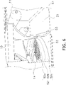
- the enclosure 51 includes a partition plate 53 that partitions a machine chamber Z1 in which the compressor 11 is installed and a heat exchange chamber Z2 in which the heat source heat exchanger 13 is installed.
- the intake part 52a is partially removed to prevent interference with the partition plate 53 or the heat source heat exchanger 13. Therefore, as shown in FIG. 2 , the intake part 52a is less widespread than the cylindrical part 52b in plan view.
- the propeller fan 14 crosses the entire area of the cylindrical part 52b in plan view or side view. In other words, the propeller fan 14 overlaps with the intake part 52a and at least partially overlaps with the blow-out part 52c.
- the inventor has investigated the transition of OA noise, 1NZ noise, and 2NZ noise while changing various dimensional ratios of the blower 50, and the like.
- the OA noise is a combination of sounds of wide frequency band components.
- the level of the OA noise corresponds to the overall noise level.
- the 1NZ noise is a sound of the component corresponding to the frequency obtained by multiplying the number of revolutions of the fan (N) by the number of blades (Z).
- the 2NZ noise is a sound of the component corresponding to twice the frequency of the 1NZ noise.
- the 1NZ noise or the 2NZ noise if louder than a sound in the surrounding frequency band, will be heard as an abnormal sound.
- FIG. 7 shows the OA noise
- FIG. 8 shows the 2NZ noise
- FIG. 9 shows the 1NZ noise.
- the lower limit of the ratio is derived as 0.14.
- the upper limit of the ratio is derived as 0.22.
- the ratio preferably satisfies the following relationship. 0.14 ⁇ H 2 H 0 ⁇ 0.22
- the upper limit of the ratio is derived as 0.21.
- the ratio preferably satisfies the following relationship. 0.14 ⁇ H 2 H 0 ⁇ 0.21
- FIG. 10 shows the OA noise
- FIG. 11 shows the 2NZ noise
- FIG. 12 shows the 1NZ noise.
- the lower limit of the ratio is derived as 0.045.
- the upper limit of the ratio is derived as 0.070.
- the ratio preferably satisfies the following relationship. 0.45 ⁇ H 2 ⁇ ⁇ 0.070
- the upper limit of the ratio is derived as 0.065.
- the ratio preferably satisfies the following relationship. 0.045 ⁇ H 2 ⁇ ⁇ 0.065
- FIG. 13 shows the OA noise
- FIG. 14 shows the 2NZ noise
- FIG. 15 shows the 1NZ noise.
- the lower limit of the ratio is derived as 0.060.
- the upper limit of the ratio is derived as 0.095.
- the ratio preferably satisfies the following relationship. 0.060 ⁇ H 2 L ⁇ 0.095
- the upper limit of the ratio is derived as 0.090.
- the ratio preferably satisfies the following relationship. 0.060 ⁇ H 2 L ⁇ 0.090
- FIG. 16 shows the OA noise
- FIG. 17 shows the 2NZ noise
- FIG. 18 shows the 1NZ noise.
- the lower limit of the ratio is derived as 0.070.
- the upper limit of the ratio is derived as 0.095.
- the ratio preferably satisfies the following relationship. 0.070 ⁇ Ri L ⁇ 0.095
- the upper limit of the ratio is derived as 0.090.
- the ratio preferably satisfies the following relationship. 0.070 ⁇ Ri L ⁇ 0.090
- FIG. 19 shows the OA noise
- FIG. 20 shows the 2NZ noise
- FIG. 21 shows the 1NZ noise.
- the lower limit of the ratio is derived as 0.16.
- the upper limit of the ratio is derived as 0.22.
- the ratio preferably satisfies the following relationship. 0.16 ⁇ Ri H 0 ⁇ 0.22
- the upper limit of the ratio is derived as 0.21.
- the ratio preferably satisfies the following relationship. 0.16 ⁇ Ri H 0 ⁇ 0.21
- FIG. 22 shows the OA noise
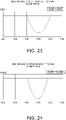
- FIG. 23 shows the 2NZ noise
- FIG. 24 shows the 1NZ noise.
- the lower limit of the ratio is derived as 0.050.
- the upper limit of the ratio is derived as 0.070.
- the ratio preferably satisfies the following relationship. 0.050 ⁇ Ri ⁇ ⁇ 0.070
- the upper limit of the ratio is derived as 0.065.
- the ratio preferably satisfies the following relationship. 0.050 ⁇ Ri ⁇ ⁇ 0.065
- the above-described configuration can suppress the OA noise and the 2NZ noise, or can suppress all the OA noise, the 1NZ noise, and the 2NZ noise. Therefore, noise is suppressed in the blower 50, the heat source unit 10, or the heat pump device 100.
- the above-described heat pump device 100 is configured as an air conditioner.
- the heat pump device 100 may be a refrigeration apparatus other than the air conditioner.
- the heat pump device 100 may be a refrigerator, a freezer, a water heater, or the like.
- the propeller fan 14 includes the concave portions Y1 to Y3. Instead, the propeller fan 14 does not have to include the concave portions Y1 to Y3.
- the intake part 52a of the bell mouth 52 is partially removed. Instead, the intake part 52a of the bell mouth 52 may exist in the whole circumference.
- the bell mouth 52 includes the intake part 52a and the blow-out part 52c. Instead, the bell mouth 52 may include only one of the intake part 52a and the blow-out part 52c. Furthermore, the bell mouth 52 needs to include none of the intake part 52a and the blow-out part 52c.
- Patent Literature 1 Japanese Patent No. 4140236
Landscapes
- Engineering & Computer Science (AREA)
- Mechanical Engineering (AREA)
- General Engineering & Computer Science (AREA)
- Structures Of Non-Positive Displacement Pumps (AREA)
Abstract

where a length of the blade (141, 142, 143) in the rotation axis (RA) direction is H0, and a length of the cylindrical part (52b) in the rotation axis (RA) direction is H2.
Description
- The present disclosure relates to a blower to be used in an air conditioner and a heat pump unit used in an air conditioner.
- Patent Literature 1 (
Japanese Patent No. 4140236 - Noise emitted by a blower needs to be suppressed. The noise includes noise from normal operating sound and noise at a specific frequency. To suppress the noise at a specific frequency, a fan at unequal pitches may be used in the blower. However, optimized design to reduce both the noise from normal operating sound and the noise at a specific frequency has not been given much consideration in the past.
- A blower of a first aspect includes a propeller fan and an enclosure. The propeller fan rotates around a rotation axis and includes a plurality of blades at unequal pitches. The enclosure houses the propeller fan, includes a bell mouth, and has a depth L. The bell mouth includes a cylindrical part parallel to the rotation axis. A relationship of

where a length of the blade in a rotation axis direction is H0 and a length of the cylindrical part in the rotation axis direction is H2. - This configuration can suppress noise.
- The blower of a second aspect is the blower of the first aspect, in which a relationship of

- This configuration can suppress noise more.
- The blower of a third aspect includes a propeller fan and an enclosure. The propeller fan rotates around a rotation axis and includes a plurality of blades at unequal pitches. The enclosure houses the propeller fan, includes a bell mouth, and has a depth L. The bell mouth includes a cylindrical part parallel to the rotation axis. A relationship of

where a diameter of the propeller fan is ϕ and a length of the cylindrical part in a rotation axis direction is H2. - This configuration can suppress noise.
- The blower of a fourth aspect is the blower of the third aspect, in which a relationship of

- This configuration can suppress noise more.
- The blower of a fifth aspect is the blower of any one of the first aspect to the fourth aspect, in which a relationship of

- This configuration can suppress noise.
- The blower of a sixth aspect is the blower of the fifth aspect, in which a relationship of

- This configuration can suppress noise more.
- The blower of a seventh aspect is the blower of the fifth aspect or the sixth aspect, in which the bell mouth further includes an intake part of a radius of curvature Ri.
- A relationship of

- This configuration can suppress noise.
- The blower of an eighth aspect is the blower of the seventh aspect, in which a relationship of

- This configuration can suppress noise more.
- The blower of a ninth aspect is the blower of any one of the first aspect to the sixth aspect, in which the bell mouth further includes an intake part of a radius of curvature Ri. A relationship of

where the length of the blade in the rotation axis direction is H0. - This configuration can suppress noise.
- The blower of a tenth aspect is the blower of the ninth aspect, in which a relationship of

- This configuration can suppress noise more.
- The blower of an eleventh aspect is the blower of any one of the first aspect to the sixth aspect, in which the bell mouth further includes an intake part of a radius of curvature Ri. A relationship of

where the diameter of the propeller fan is ϕ. - This configuration can suppress noise.
- The blower of a twelfth aspect is the blower of the eleventh aspect, in which a relationship of

- This configuration can suppress noise more.
- A heat pump unit of a thirteenth aspect includes:
- the blower of any one of the first aspect to the twelfth aspect; and
- a heat exchanger configured to exchange heat between air in an air flow formed by the blower and a refrigerant.
- This configuration can suppress noise of the heat pump unit.
-
-
FIG. 1 is a circuit diagram of aheat pump device 100. -
FIG. 2 is a plan view of the interior of aheat source unit 10. -
FIG. 3 is a front view of apropeller fan 14. -
FIG. 4 is a side view of the interior of theheat source unit 10. -
FIG. 5 is an enlarged view ofFIG. 4 . -
FIG. 6 is a perspective view of the interior of theheat source unit 10. -
FIG. 7 is a graph showing transition of OA noise with respect to the ratio of length H2 to length H0. -
FIG. 8 is a graph showing transition of 2NZ noise with respect to the ratio of length H2 to length H0. -
FIG. 9 is a graph showing transition of 1NZ noise with respect to the ratio of length H2 to length H0. -
FIG. 10 is a graph showing transition of OA noise with respect to the ratio of length H2 to diameter ϕ. -
FIG. 11 is a graph showing transition of 2NZ noise with respect to the ratio of length H2 to diameter ϕ. -
FIG. 12 is a graph showing transition of 1NZ noise with respect to the ratio of length H2 to diameter ϕ. -
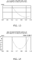
FIG. 13 is a graph showing transition of OA noise with respect to the ratio of length H2 to depth L. -
FIG. 14 is a graph showing transition of 2NZ noise with respect to the ratio of length H2 to depth L. -
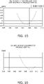
FIG. 15 is a graph showing transition of 1NZ noise with respect to the ratio of length H2 to depth L. -
FIG. 16 is a graph showing transition of OA noise with respect to the ratio of radius of curvature Ri to depth L. -
FIG. 17 is a graph showing transition of 2NZ noise with respect to the ratio of radius of curvature Ri to depth L. -
FIG. 18 is a graph showing transition of 1NZ noise with respect to the ratio of radius of curvature Ri to depth L. -
FIG. 19 is a graph showing transition of OA noise with respect to the ratio of radius of curvature Ri to length H0. -
FIG. 20 is a graph showing transition of 2NZ noise with respect to the ratio of radius of curvature Ri to length H0. -
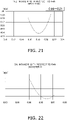
FIG. 21 is a graph showing transition of 1NZ noise with respect to the ratio of radius of curvature Ri to length H0. -
FIG. 22 is a graph showing transition of OA noise with respect to the ratio of radius of curvature Ri to diameter ϕ. -
FIG. 23 is a graph showing transition of 2NZ noise with respect to the ratio of radius of curvature Ri to diameter ϕ. -
FIG. 24 is a graph showing transition of 1NZ noise with respect to the ratio of radius of curvature Ri to diameter ϕ. -
FIG. 1 is a circuit diagram of aheat pump device 100 configured as an air conditioner. Theheat pump device 100 includes aheat source unit 10, autilization unit 20, and aconnection piping 30. As will be described later, theheat source unit 10 includes ablower 50. - The
heat source unit 10 is a heat pump unit that functions as a heat source. Theheat source unit 10 includes acompressor 11, a four-way switching valve 12, a heatsource heat exchanger 13, ablower 50, anexpansion valve 15, aliquid shutoff valve 17, agas shutoff valve 18, and a heatsource control unit 19. - The
compressor 11 sucks and compresses a low-pressure gas refrigerant to generate a high-pressure gas refrigerant. Thecompressor 11 includes acompressor motor 11a. Thecompressor motor 11a generates power necessary for compression. - The four-
way switching valve 12 switches connection of internal pipes. When theheat pump device 100 executes a cooling operation, the four-way switching valve 12 implements connection shown by solid lines ofFIG. 1 . When theheat pump device 100 executes a heating operation, the four-way switching valve 12 implements connection shown by broken lines ofFIG. 1 . - The heat
source heat exchanger 13 exchanges heat between the refrigerant and air. In the cooling operation, the heatsource heat exchanger 13 functions as a heat radiator (or condenser). In the heating operation, the heatsource heat exchanger 13 functions as a heat absorber (or evaporator). - The
blower 50 promotes heat exchange by the heatsource heat exchanger 13. The heatsource heat exchanger 13 exchanges heat between air in an air flow formed by theblower 50, and the refrigerant. Theblower 50 includes apropeller fan 14 and apropeller fan motor 14a. Thepropeller fan motor 14a generates power necessary for moving thepropeller fan 14. The structure of theblower 50 will be described later. - The
expansion valve 15 is a valve with adjustable opening degree. Theexpansion valve 15 decompresses the refrigerant. Furthermore, theexpansion valve 15 controls a flow rate of the refrigerant. - The
liquid shutoff valve 17 can shut off a refrigerant flow path. Theliquid shutoff valve 17 is closed, for example, by an installation worker during installation of theheat pump device 100 or the like. - The
gas shutoff valve 18 can shut off the refrigerant flow path. Thegas shutoff valve 18 is closed, for example, by an installation worker during installation of theheat pump device 100 or the like. - The heat
source control unit 19 includes a microcomputer and a memory. The heatsource control unit 19 controls thecompressor motor 11a, the four-way switching valve 12, thepropeller fan motor 14a, theexpansion valve 15, and the like. The memory stores software for controlling these parts. - The
utilization unit 20 provides a user with low-temperature heat or high-temperature heat. Theutilization unit 20 includes autilization heat exchanger 22, autilization fan 23, and autilization control unit 29. - The
utilization heat exchanger 22 exchanges heat between the refrigerant and air. In the cooling operation, theutilization heat exchanger 22 functions as a heat absorber (or evaporator). In the heating operation, theutilization heat exchanger 22 functions as a heat radiator (or condenser). - The
utilization fan 23 promotes heat exchange by theutilization heat exchanger 22. Theutilization fan 23 includes autilization fan motor 23a. Theutilization fan motor 23a generates power necessary for moving air. - The
utilization control unit 29 includes a microcomputer and a memory. Theutilization control unit 29 controls theutilization fan motor 23a and the like. The memory stores software for controlling these parts. - The
utilization control unit 29 transmits and receives data and commands to and from the heatsource control unit 19 via a communication line CL. - The connection piping 30 guides the refrigerant moving between the
heat source unit 10 and theutilization unit 20. Theconnection piping 30 includes aliquid connection pipe 31 and agas connection pipe 32. - The
liquid connection pipe 31 mainly guides a liquid refrigerant or a gas-liquid two-phase refrigerant. Theliquid connection pipe 31 connects theliquid shutoff valve 17 to theutilization unit 20. - The
gas connection pipe 32 mainly guides a gas refrigerant. Thegas connection pipe 32 connects thegas shutoff valve 18 to theutilization unit 20. - The following description assumes that the refrigerant changes in connection with phase transition such as condensation or evaporation in the heat
source heat exchanger 13 and theutilization heat exchanger 22. However, alternatively, the refrigerant may not necessarily experience phase transition in the heatsource heat exchanger 13 and theutilization heat exchanger 22. - In the cooling operation, the refrigerant circulates in a direction indicated by arrow C in
FIG. 1 . Thecompressor 11 discharges the high-pressure gas refrigerant in a direction indicated by arrow D inFIG. 1 . After that, the high-pressure gas refrigerant reaches the heatsource heat exchanger 13 via the four-way switching valve 12. In the heatsource heat exchanger 13, the high-pressure gas refrigerant condenses to change into a high-pressure liquid refrigerant. After that, the high-pressure liquid refrigerant reaches theexpansion valve 15. In theexpansion valve 15, the high-pressure liquid refrigerant is decompressed to change into a low-pressure gas-liquid two-phase refrigerant. After that, the low-pressure gas-liquid two-phase refrigerant passes through theliquid shutoff valve 17 and theliquid connection pipe 31 to reach theutilization heat exchanger 22. In theutilization heat exchanger 22, the low-pressure gas-liquid two-phase refrigerant evaporates to change into a low-pressure gas refrigerant. In this process, air in the room where the user stays decreases in temperature. After that, the low-pressure gas refrigerant reaches thecompressor 11 via thegas connection pipe 32, thegas shutoff valve 18, and the four-way switching valve 12. After that, thecompressor 11 takes in the low-pressure gas refrigerant. - In the heating operation, the refrigerant circulates in a direction indicated by arrow H in
FIG. 1 . Thecompressor 11 discharges the high-pressure gas refrigerant in a direction indicated by arrow D inFIG. 1 . After that, the high-pressure gas refrigerant reaches theutilization heat exchanger 22 via the four-way switching valve 12, thegas shutoff valve 18, and thegas connection pipe 32. In theutilization heat exchanger 22, the high-pressure gas refrigerant condenses to change into a high-pressure liquid refrigerant. In this process, air in the room where the user stays increases in temperature. After that, the high-pressure liquid refrigerant reaches theexpansion valve 15 via theliquid connection pipe 31 and theliquid shutoff valve 17. In theexpansion valve 15, the high-pressure liquid refrigerant is decompressed to change into a low-pressure gas-liquid two-phase refrigerant. After that, the low-pressure gas-liquid two-phase refrigerant reaches the heatsource heat exchanger 13. In the heatsource heat exchanger 13, the low-pressure gas-liquid two-phase refrigerant evaporates to change into a low-pressure gas refrigerant. After that, the low-pressure gas refrigerant reaches thecompressor 11 via the four-way switching valve 12. After that, thecompressor 11 takes in the low-pressure gas refrigerant. -
FIG. 2 is a plan view of the interior of theheat source unit 10. Theheat source unit 10 is equipped with theblower 50. - The
blower 50 includes apropeller fan 14, apropeller fan motor 14a, and anenclosure 51. - The
propeller fan 14 rotates around a rotation axis RA As shown inFIG. 3 , thepropeller fan 14 includes ablade 141, ablade 142, and ablade 143 disposed at unequal pitches. The angles theblade 141, theblade 142, and theblade 143 form with each other are not equal. For example, as shown inFIG. 3 , the central angle occupied by theblade 141 is 120°, the central angle occupied by theblade 142 is 109°, and the central angle occupied by theblade 143 is 131°. Configuring thepropeller fan 14 at unequal pitches suppresses noise at a specific frequency. Specifically, the specific frequency is a frequency corresponding to the number of revolutions of the fan multiplied by the number of blades (3 in the present embodiment), and a frequency that is an integral multiple thereof. - At the trailing edge of the
blade 141, a concave portion Y1 dented toward the leading edge is formed. At the trailing edge of theblade 142, a concave portion Y2 dented toward the leading edge is formed. At the trailing edge of theblade 143, a concave portion Y3 dented toward the leading edge is formed. Providing the concave portions Y1 to Y3 increases the airflow volume transmitted by thepropeller fan 14, and suppresses the noise generated by thepropeller fan 14. - Returning to
FIG. 2 , theblade 141, theblade 142, and theblade 143 each have a length H0 in the rotation axis RA direction. Thepropeller fan 14 has a diameter ϕ. - The
propeller fan motor 14a generates power necessary for moving thepropeller fan 14. - As shown in
FIG. 2 , theenclosure 51 of theblower 50 also serves as the enclosure of theheat source unit 10. Theenclosure 51 houses thepropeller fan 14. Theenclosure 51 has a depth L. Theenclosure 51 includes abell mouth 52. - As shown in
FIG. 4 , thebell mouth 52 includes anintake part 52a, acylindrical part 52b, and a blow-outpart 52c. Thecylindrical part 52b has a cylindrical shape parallel to the rotation axis RA. Thecylindrical part 52b has a length H2 in the rotation axis RA direction. Theintake part 52a is located upstream of thecylindrical part 52b in the direction of the air flow generated by thepropeller fan 14. As shown inFIG. 5 , theintake part 52a has a curved part of the radius of curvature Ri in the periphery in side view. The blow-outpart 52c is located downstream of thecylindrical part 52b in the direction of the air flow generated by thepropeller fan 14. - As shown in
FIG. 6 , theenclosure 51 includes apartition plate 53 that partitions a machine chamber Z1 in which thecompressor 11 is installed and a heat exchange chamber Z2 in which the heatsource heat exchanger 13 is installed. Theintake part 52a is partially removed to prevent interference with thepartition plate 53 or the heatsource heat exchanger 13. Therefore, as shown inFIG. 2 , theintake part 52a is less widespread than thecylindrical part 52b in plan view. - As shown in
FIG. 2 , thepropeller fan 14 crosses the entire area of thecylindrical part 52b in plan view or side view. In other words, thepropeller fan 14 overlaps with theintake part 52a and at least partially overlaps with the blow-outpart 52c. - The inventor has investigated the transition of OA noise, 1NZ noise, and 2NZ noise while changing various dimensional ratios of the
blower 50, and the like. - Here, the OA noise is a combination of sounds of wide frequency band components. The level of the OA noise corresponds to the overall noise level.
- The 1NZ noise is a sound of the component corresponding to the frequency obtained by multiplying the number of revolutions of the fan (N) by the number of blades (Z).
- Furthermore, the 2NZ noise is a sound of the component corresponding to twice the frequency of the 1NZ noise. The 1NZ noise or the 2NZ noise, if louder than a sound in the surrounding frequency band, will be heard as an abnormal sound.
- The noise has been investigated while changing the ratio of the length H2 to the length H0.
FIG. 7 shows the OA noise,FIG. 8 shows the 2NZ noise, andFIG. 9 shows the 1NZ noise. - As shown in
FIG. 7 , when the ratio is small, the OA noise increases. Therefore, to suppress the OA noise below a predetermined level, the lower limit of the ratio is derived as 0.14. - As shown in
FIG. 8 , when the ratio is large, the 2NZ noise increases. Therefore, to suppress the 2NZ noise below a predetermined level, the upper limit of the ratio is derived as 0.22. - As described above, to suppress the OA noise and the 2NZ noise, the ratio preferably satisfies the following relationship.

- As shown in
FIG. 9 , when the ratio is large, the 1NZ noise increases. Therefore, to suppress the 1NZ noise below a predetermined level, the upper limit of the ratio is derived as 0.21. - As described above, to suppress all the OA noise, the 1NZ noise, and the 2NZ noise, the ratio preferably satisfies the following relationship.

- The noise has been investigated while changing the ratio of the length H2 to the diameter ϕ.
FIG. 10 shows the OA noise,FIG. 11 shows the 2NZ noise, andFIG. 12 shows the 1NZ noise. - As shown in
FIG. 10 , when the ratio is small, the OA noise increases. Therefore, to suppress the OA noise below a predetermined level, the lower limit of the ratio is derived as 0.045. - As shown in
FIG. 11 , when the ratio is large, the 2NZ noise increases. Therefore, to suppress the 2NZ noise below a predetermined level, the upper limit of the ratio is derived as 0.070. - As described above, to suppress the OA noise and the 2NZ noise, the ratio preferably satisfies the following relationship.

- As shown in
FIG. 12 , when the ratio is large, the 1NZ noise increases. Therefore, to suppress the 1NZ noise below a predetermined level, the upper limit of the ratio is derived as 0.065. - As described above, to suppress all the OA noise, the 1NZ noise, and the 2NZ noise, the ratio preferably satisfies the following relationship.

- The noise has been investigated while changing the ratio of the length H2 to the depth L.
FIG. 13 shows the OA noise,FIG. 14 shows the 2NZ noise, andFIG. 15 shows the 1NZ noise. - As shown in
FIG. 13 , when the ratio is small, the OA noise increases. Therefore, to suppress the OA noise below a predetermined level, the lower limit of the ratio is derived as 0.060. - As shown in
FIG. 14 , when the ratio is large, the 2NZ noise increases. Therefore, to suppress the 2NZ noise below a predetermined level, the upper limit of the ratio is derived as 0.095. - As described above, to suppress the OA noise and the 2NZ noise, the ratio preferably satisfies the following relationship.

- As shown in
FIG. 15 , when the ratio is large, the 1NZ noise increases. Therefore, to suppress the 1NZ noise below a predetermined level, the upper limit of the ratio is derived as 0.090. - As described above, to suppress all the OA noise, the 1NZ noise, and the 2NZ noise, the ratio preferably satisfies the following relationship.

- The noise has been investigated while changing the ratio of the radius of curvature Ri to the depth L.
FIG. 16 shows the OA noise,FIG. 17 shows the 2NZ noise, andFIG. 18 shows the 1NZ noise. - As shown in
FIG. 16 , when the ratio is small, the OA noise increases. Therefore, to suppress the OA noise below a predetermined level, the lower limit of the ratio is derived as 0.070. - As shown in
FIG. 17 , when the ratio is large, the 2NZ noise increases. Therefore, to suppress the 2NZ noise below a predetermined level, the upper limit of the ratio is derived as 0.095. - As described above, to suppress the OA noise and the 2NZ noise, the ratio preferably satisfies the following relationship.

- As shown in
FIG. 18 , when the ratio is large, the 1NZ noise increases. Therefore, to suppress the 1NZ noise below a predetermined level, the upper limit of the ratio is derived as 0.090. - As described above, to suppress all the OA noise, the 1NZ noise, and the 2NZ noise, the ratio preferably satisfies the following relationship.

- The noise has been investigated while changing the ratio of the radius of curvature Ri to the length H0.
FIG. 19 shows the OA noise,FIG. 20 shows the 2NZ noise, andFIG. 21 shows the 1NZ noise. - As shown in
FIG. 19 , when the ratio is small, the OA noise increases. Therefore, to suppress the OA noise below a predetermined level, the lower limit of the ratio is derived as 0.16. - As shown in
FIG. 20 , when the ratio is large, the 2NZ noise increases. Therefore, to suppress the 2NZ noise below a predetermined level, the upper limit of the ratio is derived as 0.22. - As described above, to suppress the OA noise and the 2NZ noise, the ratio preferably satisfies the following relationship.

- As shown in
FIG. 21 , when the ratio is large, the 1NZ noise increases. Therefore, to suppress the 1NZ noise below a predetermined level, the upper limit of the ratio is derived as 0.21. - As described above, to suppress all the OA noise, the 1NZ noise, and the 2NZ noise, the ratio preferably satisfies the following relationship.

- The noise has been investigated while changing the ratio of the radius of curvature Ri to the diameter ϕ.
FIG. 22 shows the OA noise,FIG. 23 shows the 2NZ noise, andFIG. 24 shows the 1NZ noise. - As shown in
FIG. 22 , when the ratio is small, the OA noise increases. Therefore, to suppress the OA noise below a predetermined level, the lower limit of the ratio is derived as 0.050. - As shown in
FIG. 23 , when the ratio is large, the 2NZ noise increases. Therefore, to suppress the 2NZ noise below a predetermined level, the upper limit of the ratio is derived as 0.070. - As described above, to suppress the OA noise and the 2NZ noise, the ratio preferably satisfies the following relationship.

- As shown in
FIG. 24 , when the ratio is large, the 1NZ noise increases. Therefore, to suppress the 1NZ noise below a predetermined level, the upper limit of the ratio is derived as 0.065. - As described above, to suppress all the OA noise, the 1NZ noise, and the 2NZ noise, the ratio preferably satisfies the following relationship.

- The above-described configuration can suppress the OA noise and the 2NZ noise, or can suppress all the OA noise, the 1NZ noise, and the 2NZ noise. Therefore, noise is suppressed in the
blower 50, theheat source unit 10, or theheat pump device 100. - The above-described
heat pump device 100 is configured as an air conditioner. Instead, theheat pump device 100 may be a refrigeration apparatus other than the air conditioner. For example, theheat pump device 100 may be a refrigerator, a freezer, a water heater, or the like. - In the above-described configuration, the
propeller fan 14 includes the concave portions Y1 to Y3. Instead, thepropeller fan 14 does not have to include the concave portions Y1 to Y3. - In the above-described configuration, the
intake part 52a of thebell mouth 52 is partially removed. Instead, theintake part 52a of thebell mouth 52 may exist in the whole circumference. - In the above-described configuration, the
bell mouth 52 includes theintake part 52a and the blow-outpart 52c. Instead, thebell mouth 52 may include only one of theintake part 52a and the blow-outpart 52c. Furthermore, thebell mouth 52 needs to include none of theintake part 52a and the blow-outpart 52c. - The embodiment of the present disclosure has been described above, but it will be understood that various changes to forms and details can be made without departing from the gist and scope of the present disclosure as set forth in the claims.
-
- 10: heat source unit (heat pump unit)
- 14: propeller fan
- 14a: propeller fan motor
- 50: blower
- 51: enclosure
- 52: bell mouth
- 52a: intake part
- 52b: cylindrical part
- 52c: blow-out part
- 100: heat pump device
- 141: blade
- 142: blade
- 143: blade
- H0: length
- H2: length
- L: depth
- RA: rotation axis
- Ri: radius of curvature
- ϕ: diameter
- Patent Literature 1:
Japanese Patent No. 4140236
Claims (13)
- A blower (50) comprising:a propeller fan (14) configured to rotate around a rotation axis (RA) and including a plurality of blades (141, 142, 143) at unequal pitches; andan enclosure (51) housing the propeller fan, including a bell mouth (52), and having a depth L,whereinthe bell mouth includes a cylindrical part (52b) parallel to the rotation axis, anda relationship of
 where a length of the blade is H0 in a rotation axis direction of and a length of the cylindrical part in the rotation axis direction is H2.
 - The blower according to claim 1, wherein
a relationship of
- A blower (50) comprising:a propeller fan (14) configured to rotate around a rotation axis (RA) and including a plurality of blades (141, 142, 143) at unequal pitches; andan enclosure (51) housing the propeller fan, including a bell mouth (52), and having a depth L,whereinthe bell mouth includes a cylindrical part (52b) parallel to the rotation axis, anda relationship of
 where a diameter of the propeller fan is ϕ and a length of the cylindrical part in the rotation axis direction is H2.
 - The blower according to claim 3, wherein
a relationship of
- The blower according to any one of claims 1 to 4, wherein
a relationship of
- The blower according to claim 5, wherein
a relationship of
- The blower according to claim 5 or 6, whereinthe bell mouth further includes an intake part (52a) of a radius of curvature Ri, anda relationship of

- The blower according to claim 7, wherein
a relationship of
- The blower according to any one of claims 1 to 6, whereinthe bell mouth further includes an intake part (52a) of a radius of curvature Ri, anda relationship of
 where the length of the blade in the rotation axis direction is H0.
 - The blower according to claim 9, wherein
a relationship of
- The blower according to any one of claims 1 to 6, whereinthe bell mouth further includes an intake part (52a) of a radius of curvature Ri, anda relationship of
 where the diameter of the propeller fan is ϕ.
 - The blower according to claim 11, wherein
a relationship of
- A heat pump unit (10) comprising:the blower (50) according to any one of claims 1 to 12; anda heat exchanger (13) configured to exchange heat between air in an air flow formed by the blower and a refrigerant.
Applications Claiming Priority (2)
| Application Number | Priority Date | Filing Date | Title |
|---|---|---|---|
| JP2019153797A JP7173939B2 (en) | 2019-08-26 | 2019-08-26 | Blower and heat pump unit |
| PCT/JP2020/031499 WO2021039597A1 (en) | 2019-08-26 | 2020-08-20 | Blowing device and heat pump unit |
Publications (2)
| Publication Number | Publication Date |
|---|---|
| EP4023891A1 true EP4023891A1 (en) | 2022-07-06 |
| EP4023891A4 EP4023891A4 (en) | 2022-10-19 |
Family
ID=74677995
Family Applications (1)
| Application Number | Title | Priority Date | Filing Date |
|---|---|---|---|
| EP20857322.0A Withdrawn EP4023891A4 (en) | 2019-08-26 | 2020-08-20 | Blowing device and heat pump unit |
Country Status (5)
| Country | Link |
|---|---|
| US (1) | US12331752B2 (en) |
| EP (1) | EP4023891A4 (en) |
| JP (1) | JP7173939B2 (en) |
| CN (1) | CN114341555B (en) |
| WO (1) | WO2021039597A1 (en) |
Cited By (1)
| Publication number | Priority date | Publication date | Assignee | Title |
|---|---|---|---|---|
| DE102024203258A1 (en) * | 2024-04-10 | 2025-10-16 | Ziehl-Abegg Se | Support basket for a fan, fan, heat pump and method for producing a support basket |
Family Cites Families (42)
| Publication number | Priority date | Publication date | Assignee | Title |
|---|---|---|---|---|
| JPS5525555A (en) * | 1978-08-12 | 1980-02-23 | Hitachi Ltd | Impeller |
| JPS6165097A (en) * | 1984-09-06 | 1986-04-03 | Mitsubishi Electric Corp | Axial fan |
| KR0140195B1 (en) * | 1990-03-07 | 1998-07-01 | 다나까 다로오 | Press-fit Axial Blowers |
| JPH04350399A (en) * | 1991-05-28 | 1992-12-04 | Mitsubishi Motors Corp | Sirocco fan |
| US5525036A (en) * | 1991-11-29 | 1996-06-11 | Goldstar Co., Ltd. | Suction structure of a sirocco fan housing |
| JPH05223093A (en) * | 1992-02-07 | 1993-08-31 | Matsushita Electric Ind Co Ltd | Blower |
| US6499948B1 (en) * | 2000-02-07 | 2002-12-31 | Penn Ventilation, Inc. | Shroud and axial fan therefor |
| DE10058857A1 (en) * | 2000-11-27 | 2002-06-06 | Alstom Switzerland Ltd | Gas-cooled machine, especially a turbogenerator |
| JP4140236B2 (en) | 2000-12-28 | 2008-08-27 | ダイキン工業株式会社 | Blower and outdoor unit for air conditioner |
| WO2002053919A1 (en) * | 2000-12-28 | 2002-07-11 | Daikin Industries, Ltd. | Blower, and outdoor unit for air conditioner |
| JP3919496B2 (en) * | 2001-10-15 | 2007-05-23 | ヤンマー株式会社 | RADIATOR FAN AND ENGINE COOLING DEVICE USING THE SAME |
| KR20030035328A (en) * | 2001-10-31 | 2003-05-09 | 삼성전자주식회사 | Outdoor unit of air conditioner |
| JP2003184797A (en) * | 2001-12-14 | 2003-07-03 | Daikin Ind Ltd | Blower and air conditioner provided with the blower |
| JP4132826B2 (en) | 2002-01-10 | 2008-08-13 | シャープ株式会社 | Propeller fan, its mold and fluid feeder |
| JP2004301451A (en) * | 2003-03-31 | 2004-10-28 | Toshiba Kyaria Kk | Air conditioner outdoor unit |
| JP4467952B2 (en) | 2003-11-10 | 2010-05-26 | 東芝キヤリア株式会社 | Propeller fan, outdoor unit for air conditioner using this |
| US7186080B2 (en) * | 2004-08-11 | 2007-03-06 | American Standard International Inc. | Fan inlet and housing for a centrifugal blower whose impeller has forward curved fan blades |
| KR20090076031A (en) * | 2008-01-07 | 2009-07-13 | 삼성전자주식회사 | Blower and outdoor unit of air conditioner having same |
| WO2010089920A1 (en) * | 2009-02-05 | 2010-08-12 | 三菱電機株式会社 | Indoor unit for air conditioner, and air conditioner |
| JP5322900B2 (en) * | 2009-11-27 | 2013-10-23 | 三洋電機株式会社 | Bell mouth structure of blower |
| US8616844B2 (en) * | 2010-05-12 | 2013-12-31 | Deere & Company | Fan and shroud assembly |
| JP5611360B2 (en) * | 2010-09-14 | 2014-10-22 | 三菱電機株式会社 | Outdoor unit blower, outdoor unit and refrigeration cycle apparatus |
| JP5791276B2 (en) * | 2010-12-24 | 2015-10-07 | 三菱電機株式会社 | Blower, outdoor unit and refrigeration cycle apparatus |
| JP2013137008A (en) | 2011-12-28 | 2013-07-11 | Daikin Industries Ltd | Air conditioner |
| JP5549772B2 (en) * | 2012-09-28 | 2014-07-16 | ダイキン工業株式会社 | Propeller fan and air conditioner equipped with the same |
| EP2960525B1 (en) * | 2013-02-22 | 2022-10-19 | Hitachi-Johnson Controls Air Conditioning, Inc. | Propeller fan and air conditioner equipped with same |
| WO2015121989A1 (en) * | 2014-02-14 | 2015-08-20 | 三菱電機株式会社 | Axial blower |
| JP6379062B2 (en) * | 2015-03-17 | 2018-08-22 | 日立ジョンソンコントロールズ空調株式会社 | Outdoor unit of air conditioner and bell mouth provided therein |
| CN107923410B (en) * | 2015-09-08 | 2021-12-07 | 三菱电机株式会社 | Propeller fan, propeller fan device, and outdoor unit for air conditioning device |
| WO2017060973A1 (en) * | 2015-10-06 | 2017-04-13 | 三菱電機株式会社 | Air blower, outdoor unit, and refrigeration cycle device |
| GB2557130C (en) * | 2015-11-02 | 2021-03-31 | Mitsubishi Electric Corp | Outdoor Unit of Air Conditioner and Refrigeration Cycle Device |
| US11236760B2 (en) * | 2015-12-11 | 2022-02-01 | Delta Electronics, Inc. | Impeller and fan |
| EP3410026B1 (en) * | 2016-01-25 | 2023-06-07 | Mitsubishi Electric Corporation | Outdoor machine and air conditioner provided with same |
| CN107023509B (en) * | 2016-02-01 | 2020-08-11 | 宁波方太厨具有限公司 | Fan impeller and fan adopting same |
| WO2017145370A1 (en) * | 2016-02-26 | 2017-08-31 | 三菱電機株式会社 | Blowing device |
| EP3470686B1 (en) * | 2016-07-01 | 2019-12-25 | Mitsubishi Electric Corporation | Propeller fan |
| WO2018016012A1 (en) * | 2016-07-19 | 2018-01-25 | 三菱電機株式会社 | Heat source unit and refrigeration cycle device |
| JP2018084232A (en) * | 2016-11-15 | 2018-05-31 | 三星電子株式会社Samsung Electronics Co.,Ltd. | Air blower and outdoor machine for air conditioner using the same |
| JP6536631B2 (en) * | 2017-06-19 | 2019-07-03 | ダイキン工業株式会社 | Propeller fan |
| EP3643983B1 (en) * | 2017-06-23 | 2021-08-11 | Daikin Industries, Ltd. | Air conditioning indoor unit |
| GB2569943B (en) * | 2017-12-22 | 2020-07-22 | Ove Arup Ventures Ltd | A fan and an air conditioning unit comprising the same |
| CN111656019B (en) * | 2018-02-02 | 2022-05-17 | 三菱电机株式会社 | Axial blower |
-
2019
- 2019-08-26 JP JP2019153797A patent/JP7173939B2/en active Active
-
2020
- 2020-08-20 WO PCT/JP2020/031499 patent/WO2021039597A1/en not_active Ceased
- 2020-08-20 EP EP20857322.0A patent/EP4023891A4/en not_active Withdrawn
- 2020-08-20 CN CN202080059831.XA patent/CN114341555B/en active Active
-
2022
- 2022-02-22 US US17/677,819 patent/US12331752B2/en active Active
Cited By (1)
| Publication number | Priority date | Publication date | Assignee | Title |
|---|---|---|---|---|
| DE102024203258A1 (en) * | 2024-04-10 | 2025-10-16 | Ziehl-Abegg Se | Support basket for a fan, fan, heat pump and method for producing a support basket |
Also Published As
| Publication number | Publication date |
|---|---|
| US12331752B2 (en) | 2025-06-17 |
| EP4023891A4 (en) | 2022-10-19 |
| WO2021039597A1 (en) | 2021-03-04 |
| US20220178382A1 (en) | 2022-06-09 |
| CN114341555B (en) | 2023-09-19 |
| JP2021032162A (en) | 2021-03-01 |
| JP7173939B2 (en) | 2022-11-16 |
| CN114341555A (en) | 2022-04-12 |
Similar Documents
| Publication | Publication Date | Title |
|---|---|---|
| AU2009339555B2 (en) | Indoor unit for air conditioner, and air conditioner | |
| US11226120B2 (en) | Outdoor unit of air conditioner | |
| CN109247023B (en) | Centrifugal blower, air conditioning device and refrigeration cycle device | |
| CN105588186A (en) | Wall-hung air conditioner indoor unit and air conditioner | |
| CN111247345A (en) | Centrifugal blower, blower device, air conditioner, and refrigeration cycle device | |
| KR102620362B1 (en) | Air conditioner | |
| CN112283800A (en) | Machine and air conditioner in air conditioning | |
| CN216346604U (en) | Indoor unit of air conditioner | |
| US12331752B2 (en) | Blower and heat pump unit | |
| TWI754505B (en) | Scroll casing of a telecentric blower, a telecentric blower equipped with the scroll casing, an air conditioner, and a refrigeration cycle device | |
| JP6856165B2 (en) | Blower and refrigeration system with a blower | |
| JP6463497B2 (en) | Blower, outdoor unit and refrigeration cycle apparatus | |
| CN221197547U (en) | Hanging air conditioner | |
| JP6437110B2 (en) | Indoor unit and air conditioner | |
| JP2018096312A (en) | Blower and refrigeration apparatus having a blower | |
| EP4484754A1 (en) | Cross-flow fan | |
| CN222849367U (en) | Duct machine | |
| CN212869964U (en) | Air conditioner | |
| EP3845819A1 (en) | Outdoor unit and refrigeration cycle device | |
| WO2017085889A1 (en) | Centrifugal fan, air conditioner, and refrigerating cycle device | |
| CN109891101A (en) | Propeller fan, outdoor unit and refrigerating circulatory device | |
| JPWO2020136797A1 (en) | Outdoor unit and refrigeration cycle device | |
| HK1180758A1 (en) | Blower for outdoor unit, outdoor unit, and refrigeration cycle device |
Legal Events
| Date | Code | Title | Description |
|---|---|---|---|
| STAA | Information on the status of an ep patent application or granted ep patent |
Free format text: STATUS: THE INTERNATIONAL PUBLICATION HAS BEEN MADE |
|
| PUAI | Public reference made under article 153(3) epc to a published international application that has entered the european phase |
Free format text: ORIGINAL CODE: 0009012 |
|
| STAA | Information on the status of an ep patent application or granted ep patent |
Free format text: STATUS: REQUEST FOR EXAMINATION WAS MADE |
|
| 17P | Request for examination filed |
Effective date: 20220309 |
|
| AK | Designated contracting states |
Kind code of ref document: A1 Designated state(s): AL AT BE BG CH CY CZ DE DK EE ES FI FR GB GR HR HU IE IS IT LI LT LU LV MC MK MT NL NO PL PT RO RS SE SI SK SM TR |
|
| A4 | Supplementary search report drawn up and despatched |
Effective date: 20220920 |
|
| RIC1 | Information provided on ipc code assigned before grant |
Ipc: F04D 29/52 20060101ALI20220914BHEP Ipc: F04D 29/54 20060101ALI20220914BHEP Ipc: F04D 29/38 20060101ALI20220914BHEP Ipc: F04D 29/66 20060101AFI20220914BHEP |
|
| DAV | Request for validation of the european patent (deleted) | ||
| DAX | Request for extension of the european patent (deleted) | ||
| RAP3 | Party data changed (applicant data changed or rights of an application transferred) |
Owner name: DAIKIN INDUSTRIES, LTD. |
|
| STAA | Information on the status of an ep patent application or granted ep patent |
Free format text: STATUS: EXAMINATION IS IN PROGRESS |
|
| P01 | Opt-out of the competence of the unified patent court (upc) registered |
Effective date: 20230525 |
|
| 17Q | First examination report despatched |
Effective date: 20230630 |
|
| STAA | Information on the status of an ep patent application or granted ep patent |
Free format text: STATUS: THE APPLICATION IS DEEMED TO BE WITHDRAWN |
|
| 18D | Application deemed to be withdrawn |
Effective date: 20240409 |