EP4023836A1 - A method for packaging an underroof collar, a packed underroof collar, and a folding tool for folding an underroof collar - Google Patents
A method for packaging an underroof collar, a packed underroof collar, and a folding tool for folding an underroof collar Download PDFInfo
- Publication number
- EP4023836A1 EP4023836A1 EP22150067.1A EP22150067A EP4023836A1 EP 4023836 A1 EP4023836 A1 EP 4023836A1 EP 22150067 A EP22150067 A EP 22150067A EP 4023836 A1 EP4023836 A1 EP 4023836A1
- Authority
- EP
- European Patent Office
- Prior art keywords
- collar
- members
- underroof
- tool
- folding
- Prior art date
- Legal status (The legal status is an assumption and is not a legal conclusion. Google has not performed a legal analysis and makes no representation as to the accuracy of the status listed.)
- Granted
Links
Images


Classifications
-
- E—FIXED CONSTRUCTIONS
- E04—BUILDING
- E04D—ROOF COVERINGS; SKY-LIGHTS; GUTTERS; ROOF-WORKING TOOLS
- E04D13/00—Special arrangements or devices in connection with roof coverings; Protection against birds; Roof drainage ; Sky-lights
- E04D13/03—Sky-lights; Domes; Ventilating sky-lights
- E04D13/0305—Supports or connecting means for sky-lights of flat or domed shape
- E04D13/031—Supports or connecting means for sky-lights of flat or domed shape characterised by a frame for connection to an inclined roof
-
- B—PERFORMING OPERATIONS; TRANSPORTING
- B65—CONVEYING; PACKING; STORING; HANDLING THIN OR FILAMENTARY MATERIAL
- B65B—MACHINES, APPARATUS OR DEVICES FOR, OR METHODS OF, PACKAGING ARTICLES OR MATERIALS; UNPACKING
- B65B25/00—Packaging other articles presenting special problems
-
- B—PERFORMING OPERATIONS; TRANSPORTING
- B65—CONVEYING; PACKING; STORING; HANDLING THIN OR FILAMENTARY MATERIAL
- B65B—MACHINES, APPARATUS OR DEVICES FOR, OR METHODS OF, PACKAGING ARTICLES OR MATERIALS; UNPACKING
- B65B63/00—Auxiliary devices, not otherwise provided for, for operating on articles or materials to be packaged
- B65B63/04—Auxiliary devices, not otherwise provided for, for operating on articles or materials to be packaged for folding or winding articles, e.g. gloves or stockings
-
- B—PERFORMING OPERATIONS; TRANSPORTING
- B65—CONVEYING; PACKING; STORING; HANDLING THIN OR FILAMENTARY MATERIAL
- B65H—HANDLING THIN OR FILAMENTARY MATERIAL, e.g. SHEETS, WEBS, CABLES
- B65H45/00—Folding thin material
- B65H45/02—Folding limp material without application of pressure to define or form crease lines
- B65H45/06—Folding webs
- B65H45/10—Folding webs transversely
- B65H45/101—Folding webs transversely in combination with laying, i.e. forming a zig-zag pile
- B65H45/107—Folding webs transversely in combination with laying, i.e. forming a zig-zag pile by means of swinging or reciprocating guide bars
-
- E—FIXED CONSTRUCTIONS
- E04—BUILDING
- E04D—ROOF COVERINGS; SKY-LIGHTS; GUTTERS; ROOF-WORKING TOOLS
- E04D13/00—Special arrangements or devices in connection with roof coverings; Protection against birds; Roof drainage ; Sky-lights
- E04D13/14—Junctions of roof sheathings to chimneys or other parts extending above the roof
- E04D13/147—Junctions of roof sheathings to chimneys or other parts extending above the roof specially adapted for inclined roofs
- E04D13/1473—Junctions of roof sheathings to chimneys or other parts extending above the roof specially adapted for inclined roofs specially adapted to the cross-section of the parts extending above the roof
- E04D13/1475—Junctions of roof sheathings to chimneys or other parts extending above the roof specially adapted for inclined roofs specially adapted to the cross-section of the parts extending above the roof wherein the parts extending above the roof have a generally rectangular cross-section
Definitions
- the present invention relates to a method for packaging an underroof collar for use in water-proofing a joint between a roof structure and a window frame, said underroof collar comprising a first set of collar members and a second set of collar members extending perpendicular to the first set of collar members, said collar members being configured for extending along frame members of a rectangular window frame in a mounted state, each collar member including an inner rim part and an outer skirt part intended for coming into engagement with the roof structure, and said inner rim parts together delimiting a collar opening, where each collar member has a length extending in parallel with the inner rim part, where each of said collar members comprises a centre section extending between the collar members of the other set of collar members along the collar opening, and where the underroof collar has an interior side adapted for facing the roof structure and window frame in a mounted state and an opposite exterior side adapted for facing away from the roof structure and the window frame in a mounted state, said method including the step of folding the underroof collar along two or more folding lines
- Underroof collars of the kind mentioned above are known for example from EP0994992B1 , EP2952646A1 , and EP2284329A2 , and since they are made from soft textile-like materials they can been packaged in many ways. Focus have primarily been on making the packed underroof collar as compact as possible in order to reduce the space needed for storage and transportation, but in later years focus has shifted towards making the installation of roof window related products, such as underroof collars, easier in order to avoid errors in mounting.
- One example is found in the applicants' own prior patent application WO2018/210937 , where the underroof collar was provided with an engagement zone adapted for engagement with a window frame or the like.
- the elongate tool members act as carriers engaging with and moving the material of the underroof collar so that it folds over each tool member along a folding line extending in parallel to the length of the tool member.
- the folds will remain, leaving the underroof collar in a folded state.
- One or more tool members may be stationary, but at present it is considered advantageous that all tool members are individually moveable.
- One or more tool members may remain idle during some uses, for example during folding of small underroof collars.
- the length of tool members used is preferably longer than the length of the collar members of the first set so that one fold extending over the entire underroof collar is created by one tool member. It is, however, also possible to use tool members each engaging only with one of the collar members of the second set, i.e. using one set of tool members at one side of the underroof collar and another set of tool members at the other side of the underroof collar.
- the surface properties of the tool members may influence on the resulting configuration of the folded underroof collar. If the tool members have a smooth surface, the material of the underroof collar may slide over their surfaces, whereas a rough or profiled surface may result in friction against the material of the underroof, whereby it may be retained. All tool members do not have to be identical, and differences in surface properties may contribute to controlling the folding of the underroof collar. It is even possible to provide conveyors, such as belts, cables, or rollers, on the surface of one or more tool members. By activating such conveyors, the underroof collar may be forced to move in relation to the tool member in question. A similar effect may be achieved by rotating a tool member with rough or profiled surface about its length direction.
- All tool members should preferably remain parallel to each other at all stages of the folding process to ensure that the folds are parallel, but a slight mutual angling of tool members may be advantageous when releasing the underroof collar from the folding tool to reduce friction between the tool members and the underroof collar.
- the tool members move in on the hanging underroof collar from opposite sides and push the underroof collar in front of them so that each tool member creates a fold and the underroof collar is forced into a zig-zag configuration where sections of the underroof collar extend from one tool member to another.
- the angle of these sections of the underroof collar relative to each other and to the initial vertical orientation of the underroof collar will depend on the mutual distance between the tool members in the vertical direction and on how far across the tool members are moved.
- Another factor influencing on the resulting configuration of the underroof collar is the cross-sectional shape and size of the tool members.
- the tool members have a circular cross-section with a diameter of at least 10 mm so that the primary folds created on the underroof collar are not sharply defined and the underroof collar may slide over the tool members as they move across.
- the distance between the free hanging collar member of the first set and the folding tool will gradually decrease as the tool members move across and sections of the underroof collar come to extend between them. It is also possible to move the location of fixation, the free hanging collar member, the folding tool, and/or individual tool members in relation to each other in the vertical direction to control the folding.
- the fixation of the underroof collar may for example be achieved by clamping the underroof collar between two rail member of the folding tool, thus providing a linear support for the underroof collar, but it is also possible to use two or more local fixations, such as clips.
- the folding method may further comprise the subsequent step C) of moving at least one of the tool members in a direction, which is substantially parallel to the plane defined by the exterior side in the hanging position in step A) so that a mutual angle between two sections of the underroof collar located on different sides of a tool member following step B) becomes smaller, said sections of the underroof collar preferably becoming substantially parallel.
- step C) of moving at least one of the tool members in a direction, which is substantially parallel to the plane defined by the exterior side in the hanging position in step A) so that a mutual angle between two sections of the underroof collar located on different sides of a tool member following step B) becomes smaller, said sections of the underroof collar preferably becoming substantially parallel.
- the underroof collar slides over at least one of the tool members during at least a part of the steps B) and C).
- the tool members used in this embodiment of the invention preferably have a rounded and smooth surface as described above.
- the method instead of steps A) and B), comprises the steps of:
- the continuous support provided by the support surface may also be advantageous if the skirt part of some of the collar members are made with a surplus of material, for example being pleated, as a surplus of material may be more difficult to manage in a hanging position.
- the members used preferably have a rough or profiled surface so that the tendency of the underroof collar to slide over the tool members due the folding steps is kept low as described above.
- step F) results in at least two tool members becoming arranged closely above each other when seen in a direction perpendicular to the support surface. As described above this will increase the precision of the folding compared to methods where the underroof collar is released in position, where the tool members are further from each other.
- the method may further comprise one or more of the following steps:
- the underroof collar is folded along two secondary folding line, each coinciding substantially with the inner rim of a collar member of the second set.
- the folding along a tertiary folding can be performed before or after the folding along one or more secondary folding lines, or the underroof collar may be folded along two or more tertiary folding lines, possibly both before and after a folding one or more secondary folding lines.
- the folding along secondary and/or tertiary folding lines may be performed by hand or using a folding tool.
- the first set of collar members are top and bottom collar members configured for extending along top and bottom frame member of the rectangular window frame, where the underroof collar is folded so that at least a part of the centre section of each side collar member is arranged on top of or underneath the top collar member, the bottom collar member, and/or a section of the side collar member located in continuation of the top collar member or the bottom collar member when seen in the length direction of said top collar member or bottom collar member, and so that the top collar member and the bottom collar member are arranged one on top of the other.
- the inner rim parts of the underroof collar will typically be configured for abutting on outer sides of the top, bottom and side members of the window frame in the mounted state, said outer sides facing away from the opening defined by the frame and extending substantially perpendicular to the plane of the roof, i.e. being substantially vertical. This means that in the mounted state the inner rim parts will extend at an angle with respect to the skirt parts, which extend over the roof structure, away from the window frame.
- the inner rim parts are preferably arranged so that they lay flat in the same plane as the outer skirt parts. This makes it easier to fold the underroof collar.
- the invention also relates to a packed underroof collar folded as described above.
- the invention further relates to a folding tool for folding the underroof collar along two or more primary folding lines, said folding tool comprising two or more elongate tool members, each having a length defining a length direction, and an activation mechanism configured for moving the elongate tool members in relation to each other in directions, which are substantially perpendicular to the length directions of the tool members, where said tool members are configured for individually engaging the underroof collar and for lifting and/or displacing it into a folded state.
- the tool members serve as carriers by being configured for engaging with and moving the material of the underroof collar so that the underroof collar folds over each tool member along a folding line extending in parallel to the length of the tool member.
- the activation mechanism may for example comprise pneumatic cylinders adapted for moving each tool member and may be controlled by a computer.
- a mechanical activation mechanism driven by a motor may be used.
- the activation mechanism is configured for moving each of the elongate tool members independently of each other to change their mutual positions.
- the activation mechanism may also or alternatively be configured for rotating one or more tool members about its own length direction and/ or for activating one or more conveyors on the surface of one or more tool members.
- the activation mechanism is also configured for moving the tool members in their length directions, which may facilitate removal of the underroof collar from the folding tool.
- the folding tool may further comprise a fixation mechanism for fixation the underroof collar in a hanging position and/or a support surface for supporting the underroof collar in a substantially horizontal position and/or a release mechanism for facilitating the removal of the underroof collar from the tool members.
- the fixation mechanism may for example comprise a pair of rail members configured for clamping the underroof collar between them.
- the support surface may comprise a table and/or a belt conveyor on which the underroof collar may rest.
- the release mechanism may for example comprise clamps for holding on to the underroof collar during a retraction of the tool members and/or for pulling on the underroof collar.
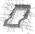
- FIG. 1 the mounting of an underroof collar 1 around a window frame 2 installed in an inclined roof structure 3 including an underroof 31 is shown.
- the packed underroof collar is arranged with a top collar member 11 at the top frame member 21 of the window frame and unfolded as shown by the arrows.
- side collar members 12 of the underroof collar come to extend alongside frame members 22 of the window frame and the bottom collar member 13 is eventually arranged along the bottom frame member 23.
- the top and bottom collar members 11, 13 here constitute a first set of collar members and the side collar members 12 constitute a second set of collar members extending perpendicular to the first set of collar members.
- Each collar member 11, 12, 13 includes an inner rim part 121, 131 and an outer skirt part 112, 122, 132.
- the inner parts delimit a collar opening 10 and are oriented so that they stand upright at an angle with respect to the skirt parts and will thus be parallel with and abut on the vertical exterior parts of the top, bottom and side members of the window frame 2 in the mounted state.
- An interior side of the outer skirt parts comes into engagement with the underroof 31 and laths 32 of the roof structure, while the exterior side 15, which is coloured grey in Fig. 1 , faces the exterior and diverts any precipitation, e.g. rain or snow, from the joint between the roof structure 3 and the window frame 2.
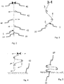
- FIGs 2-5 One method for folding an underroof collar in an automated manner is illustrated Figs 2-5 .
- Fig. 2 the underroof collar 1 is hanging under the influence of gravity from a fixation mechanism 41 of a folding tool.
- the underroof collar is shown simply as a line, as it is preferably arranged in a flattened state before being folded, but it will be understood that the presence of for example inner rim parts 121, 131, which are intended to project upwards along outer sides of the window frame in the mounted state as shown in Fig. 1 , may result in some sections of the underroof collar appearing slight thicker than others. Likewise, the presences of pleating on the side collar members 12 may result in them being slightly thicker than the top and bottom collar members 11, 13.
- the invention is not limited to the folding of an underroof collar having the exact features shown in Fig. 1 .
- the fixation mechanism 41 comprises two rail members, each having a triangular cross-sectional shape and extending into the plane of the drawing, and the underroof collar 1 is fixated by a collar member of the first set being clamped between them, in this case it is the bottom collar member 13 as shown in Fig. 1 .
- the fixation may, however, also be achieved in a different way as long as the underroof collar hangs safely.
- Each tool member 42 is a rod, having a circular cross-sectional shape and extending into the plane of the drawing, and each is connected to an activation mechanism (not shown) of the folding tool configured for moving the tool member in directions substantially perpendicular to its length direction, i.e. in the plane of the drawing.
- the tool members 42 are moved as indicated by the arrows in Fig. 2 into contact with the underroof collar.
- one tool member engages the interior side 14 of the underroof collar and two tool members engage the exterior side 15 of the underroof collar.
- the tool member 42 engaging the interior side 14 is located approximately at the centre of the underroof collar, i.e. at the centre sections of side collar members 12 extending between the top and bottom collar members 11, 13 along the collar opening 10 as shown in Fig. 1 .
- the tool members 42 have a length in the direction extending into the drawing in Fig.
- Fig. 3 it is seen that the movement of the tool members 42 continues until the tool member engaging the interior side 14 of the underroof collar 1 has passed a plane defined by the exterior side 15 in the hanging position in Fig. 2 , and the tool members engaging the exterior side 15 have passed a plane defined by the interior side 14 in the hanging position.
- the underroof collar is displaced by the tool members and brought into a zig-zag configuration with a soft fold at each tool member, the tool members thus defining three primary folding lines extending substantially in parallel to the length of the collar members of the first set.
- the distances between the tool members 42 is larger in Fig. 3 than in Fig. 2 . This means that the underroof collar 1 is forced to slide over the tool members during their movement and that the free hanging section 16 of the underroof collar hanging below the lowermost tool member is thus shortened.
- the tool members 42 are then moved upwards in a direction, which is substantially parallel to the plane defined by the exterior side 15 in the hanging position in Fig. 2 as illustrated by the arrows in Fig. 3 to the position illustrated in Fig. 4 .
- the distance covered by the tool members 42 during their movement may depend on the size of the underroof collar 1. A longer movement will allow the folding of a longer underroof collar. It is also possible to increase the number of tool members, for example adding one or more additional tool members below those shown in Figs 2 and 3 , and to use some of them only for the folding of underroof collars, which are longer than the one shown. Such additional tool members (not shown) may be kept idle when folding shorter underroof collars or simply move without engaging the shorter underroof collar.
- the tool members 42 are moved downwards and sideways as illustrated by the arrows in the Fig. 4 to the positions in Fig. 5 .
- the free hanging section 16 of the underroof collar comes into contact with a support surface 43 and is pulled to the side by the friction between the material of the underroof collar and the support surface. It is, however, also possible to apply a simpler pattern of movement, for example only moving the tool members 42 straight downwards towards the support surface.
- the fixation mechanism releases its grip so that the section 17 of the underroof collar previously extending between the uppermost tool member 42 and the fixation mechanism 41 falls down over the neighbouring section extending between the two uppermost tool members.
- Fig. 5 all four sections of the underroof collar are shown as extending substantially in parallel, but it is to be understood that the previously fixated section 17 will usually be resting on the neighbouring section underneath it. It is also to be understood that if applying more tool members, the number of folds and hence the number of sections arranged on top of each other will be higher.
- the underroof collar 1 is now folded along three primary folding lines and the folding tool can be retracted either in a direction into or out of the plane of the drawing, or the underroof collar can be pulled off the tool members.
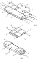
- the underroof collar is thereby left in the state shown in Fig. 6 , where the primary folding lines I-I are indicated by the dash-dotted lines, and where the top collar member 11 and the bottom collar 13 member are arranged one on top of the other.
- the actual folds on the underroof collar 1 may not be exactly linear due to the soft nature of the material typically used for underroof collars and the relatively large diameter of the tool members 42. If sharper folds are needed or desired, tool members with a smaller diameter may be used and/or both ends of the underroof collar may be fixated so that the underroof collar may be pressed against the tool members. A fixation of the section 16 hanging free in Fig. 2-4 may replace the support surface 43 in Fig. 5 , but it is presently considered advantageous that at least a part of the underroof collar 1 rests on a support surface during the release from the tool members 42, as this provides a good control of the relatively soft folded material.
- the packed underroof collar may be folded further along secondary and/or tertiary folding lines, which are indicated by the broken lines II-II and III-III and shown by the arrows a and b, respectively, in Fig. 6 .
- the underroof collar 1 If folded only along the primary folding lines I and the secondary folding lines II, which extend substantially perpendicular to the primary folding lines and along the inner rim parts of the side collar members 12, i.e. the second set of collar members, the underroof collar 1 get into the configuration in Fig. 7 .
- the corner sections of the underroof collar 1, where the side collar members 12 meet the top and bottom collar members, are arranged on top of the bottom collar member 13.
- top and bottom collar members extend over the entire width of the underroof collar
- side collar members extend over the entire height of the underroof collar
- collar members are interconnected in bevelled joints.
- top collar member 11 extend over the entire width of the underroof collar
- side and bottom collar members 12, 13 are interconnected in bevelled joints, but other combinations of different joint types are also possible.
- the underroof collar 1 gets into the configuration in Fig. 8 .
- the centre sections of the side collar members 12 are arranged on top of the bottom collar member 13.
- the corner sections or side collar members onto the top collar member 11 and/or to fold along all of the primary I, secondary II, and tertiary III folding lines.
- the underroof collar 1 may be folded along further folding lines, which will particularly be advantageous when packaging large underroof collars intended for large roof windows or like roof penetrating structures.
- FIG. 9-11 Another method for folding an underroof collar 1 is shown in Figs 9-11 .
- the underroof collar is arranged on a support surface 43 in a substantially horizontal orientation and tool members 42 corresponding to those described above with reference to Figs. 2-5 are arranged in grooves 44 in the support surface.
- the underroof collar 1 is lifted to the position shown in Fig. 10 .
- a primary folding line is created above each tool member and a third, but less well-defined primary folding line extends at the position marked c.
- the tool members 42 are then moved sideways and downwards as indicated by the arrows in Fig. 10 to the positions in Fig. 11 .
- the right-hand end-section 18 is kept back by friction when coming into contact with the support surface 43 and thus comes to lie underneath the other sections of the underroof collar.
- the tool members 42 are less smooth than in the embodiment in Figs 2-5 , as the underroof collar 1 only needs to slide over them when it is taken off the folding tool, either by retraction of the tool members, by pulling on the underroof collar or by a combination of the two.
- the size distribution of the four sections of the underroof collar 1 in Fig 11 is slightly more equal than in Fig. 5 , but this is only intended to illustrate the possibility for variation.
- the size distribution may be changed by changing the initial distance between the tool members 42 or by changing the pattern of movement of the tool members, and the surface properties of the tool members, which define the friction against the underroof collar, will also play a role.
- FIG. 12-15 A still further method for folding an underroof collar is shown in Figs 12-15 .
- the underroof collar 1 is initially arranged in a horizontal position on a conveyor 45, here illustrated as a roller conveyor, and then passes over the edge of the conveyor at the right-hand side in Fig. 12 .
- the underroof collar passes between two tool members 42, which are moved sideways as shown by the arrows in substantially the same way as described with reference to Fig 2 .
- the third and lowermost tool member engages later than the first two as shown in Fig. 13 , waiting until the free hanging end of the underroof collar has reached down to it.
- the trailing end of the underroof collar 1 comes off the conveyor as shown in Fig.
- the forward movement of the underroof collar 1 is here described as being driven by the conveyor 45, but it is also possible to use one or more of the tool members as drive members. This may for example be done by making them rotatable and having a high coefficient of friction in contact with the underroof collar or by making a belt conveyor pass over them. In this way the tool members may pull the underroof collar off the conveyor, which may then be passive or only active during an initial phase of the folding process. The conveyor may then also be replaced with an entirely passive support surface as described with reference to Figs 9-11 .
Landscapes
- Engineering & Computer Science (AREA)
- Architecture (AREA)
- Civil Engineering (AREA)
- Structural Engineering (AREA)
- Mechanical Engineering (AREA)
- Roof Covering Using Slabs Or Stiff Sheets (AREA)
Abstract
Description
- The present invention relates to a method for packaging an underroof collar for use in water-proofing a joint between a roof structure and a window frame, said underroof collar comprising a first set of collar members and a second set of collar members extending perpendicular to the first set of collar members, said collar members being configured for extending along frame members of a rectangular window frame in a mounted state, each collar member including an inner rim part and an outer skirt part intended for coming into engagement with the roof structure, and said inner rim parts together delimiting a collar opening, where each collar member has a length extending in parallel with the inner rim part, where each of said collar members comprises a centre section extending between the collar members of the other set of collar members along the collar opening, and where the underroof collar has an interior side adapted for facing the roof structure and window frame in a mounted state and an opposite exterior side adapted for facing away from the roof structure and the window frame in a mounted state, said method including the step of folding the underroof collar along two or more folding lines.
- Underroof collars of the kind mentioned above are known for example from
EP0994992B1 ,EP2952646A1 , andEP2284329A2 , and since they are made from soft textile-like materials they can been packaged in many ways. Focus have primarily been on making the packed underroof collar as compact as possible in order to reduce the space needed for storage and transportation, but in later years focus has shifted towards making the installation of roof window related products, such as underroof collars, easier in order to avoid errors in mounting. One example is found in the applicants' own prior patent applicationWO2018/210937 , where the underroof collar was provided with an engagement zone adapted for engagement with a window frame or the like. - It, however, remains a problem that as underroof collars are difficult to handle during packaging as they are relatively large and made from light and soft materials.
- With this background, it is an object of the invention to provide an improved method for packaging an underroof collar, a packed underroof collar, and a folding tool for folding an underroof collar.
- This and further objects are achieved with a method as described above, where the underroof collar is folded along two or more primary folding lines extending substantially in parallel to the length of the collar members of the first set using a folding tool comprising two or more elongate tool members, which are moveable in relation to each other, each of said tool members having a length extending in parallel to the length of the collar members of the first set when in use and defining a length direction, and that the underroof collar is lifted and/or displaced by the tool members thereby moving the collar members of the second set in relation to the collar members of the first set, so that at least a part of the centre sections of the collar members of the second set are arranged on top of at least one of the collar member of the first set.
- The elongate tool members act as carriers engaging with and moving the material of the underroof collar so that it folds over each tool member along a folding line extending in parallel to the length of the tool member. When the tool members are subsequently retracted from the underroof collar or the underroof collar taken off the folding tool, the folds will remain, leaving the underroof collar in a folded state.
- One or more tool members may be stationary, but at present it is considered advantageous that all tool members are individually moveable.
- One or more tool members may remain idle during some uses, for example during folding of small underroof collars.
- The length of tool members used is preferably longer than the length of the collar members of the first set so that one fold extending over the entire underroof collar is created by one tool member. It is, however, also possible to use tool members each engaging only with one of the collar members of the second set, i.e. using one set of tool members at one side of the underroof collar and another set of tool members at the other side of the underroof collar.
- In addition to the pattern of movement of the tool members, the surface properties of the tool members may influence on the resulting configuration of the folded underroof collar. If the tool members have a smooth surface, the material of the underroof collar may slide over their surfaces, whereas a rough or profiled surface may result in friction against the material of the underroof, whereby it may be retained. All tool members do not have to be identical, and differences in surface properties may contribute to controlling the folding of the underroof collar. It is even possible to provide conveyors, such as belts, cables, or rollers, on the surface of one or more tool members. By activating such conveyors, the underroof collar may be forced to move in relation to the tool member in question. A similar effect may be achieved by rotating a tool member with rough or profiled surface about its length direction.
- It is presently considered advantageous to release the underroof collar from the folding tool by arranging at least a part of the underroof collar so that it rests on a support surface and then retracting the tool members by moving them in their length directions, but it is also possible to for example pull the underroof collar off the folding tool, to change the angle of the tool members so that the underroof collar slides off the folding tool, or to use a combination of steps resulting in the underroof collar coming off the folding tool.
- All tool members should preferably remain parallel to each other at all stages of the folding process to ensure that the folds are parallel, but a slight mutual angling of tool members may be advantageous when releasing the underroof collar from the folding tool to reduce friction between the tool members and the underroof collar.
- In one embodiment the method for folding of the underroof collar further comprises the steps of:
- A) fixating a collar member of the first set and allowing the collar member to hang from this collar member under the influence of gravity,
- B) moving the tool members into contact with the underroof collar in directions, which are substantially perpendicular to their respective length directions, so that at least one a tool member engages the interior side of the underroof collar and at least one tool member engages the exterior side of the underroof collar,
- In other words, the tool members move in on the hanging underroof collar from opposite sides and push the underroof collar in front of them so that each tool member creates a fold and the underroof collar is forced into a zig-zag configuration where sections of the underroof collar extend from one tool member to another. The angle of these sections of the underroof collar relative to each other and to the initial vertical orientation of the underroof collar will depend on the mutual distance between the tool members in the vertical direction and on how far across the tool members are moved. Another factor influencing on the resulting configuration of the underroof collar is the cross-sectional shape and size of the tool members. It is presently considered advantageous that the tool members have a circular cross-section with a diameter of at least 10 mm so that the primary folds created on the underroof collar are not sharply defined and the underroof collar may slide over the tool members as they move across.
- If the location of fixation of the fixated collar member of the first set is stationary, the distance between the free hanging collar member of the first set and the folding tool will gradually decrease as the tool members move across and sections of the underroof collar come to extend between them. It is also possible to move the location of fixation, the free hanging collar member, the folding tool, and/or individual tool members in relation to each other in the vertical direction to control the folding.
- The fixation of the underroof collar may for example be achieved by clamping the underroof collar between two rail member of the folding tool, thus providing a linear support for the underroof collar, but it is also possible to use two or more local fixations, such as clips.
- The folding method may further comprise the subsequent step C) of moving at least one of the tool members in a direction, which is substantially parallel to the plane defined by the exterior side in the hanging position in step A) so that a mutual angle between two sections of the underroof collar located on different sides of a tool member following step B) becomes smaller, said sections of the underroof collar preferably becoming substantially parallel. In this way the underroof collar is moved further towards its intended folded state, thereby increasing the precision of the folding compared to methods where the underroof collar is released in position, where the tool members are further from each other.
- Due to the fixation of the underroof collar, it is considered advantageous that the underroof collar slides over at least one of the tool members during at least a part of the steps B) and C). To facilitate this, the tool members used in this embodiment of the invention preferably have a rounded and smooth surface as described above.
- In another embodiment, the method, instead of steps A) and B), comprises the steps of:
- D) arranging the underroof collar on a support surface, said support surface comprising openings or cavities configured for accommodating the tool members,
- E) moving the tool members into contact with the underroof collar, thereby lifting it from the support surface, the tool members being moved in directions, which are substantially perpendicular to their respective length directions, and away from the support surface, and
- F) moving the tool members in a direction along the support surface, thereby bringing at least two tool members closer to each other in a direction parallel to the support surface and shifting sections of the underroof collar in a direction parallel to the support surface.
- As the initial position of the underroof collar, when it rests on the support surface, is now substantially horizontal there is no need for a fixation of the underroof collar. The continuous support provided by the support surface may also be advantageous if the skirt part of some of the collar members are made with a surplus of material, for example being pleated, as a surplus of material may be more difficult to manage in a hanging position.
- In this embodiment the members used preferably have a rough or profiled surface so that the tendency of the underroof collar to slide over the tool members due the folding steps is kept low as described above.
- To move the underroof collar further towards its intended folded state, it is presently considered advantageous that step F) results in at least two tool members becoming arranged closely above each other when seen in a direction perpendicular to the support surface. As described above this will increase the precision of the folding compared to methods where the underroof collar is released in position, where the tool members are further from each other.
- Regardless how the folding tool is embodied, the method may further comprise one or more of the following steps:
- G) Folding the underroof collar along a secondary folding line extending substantially perpendicular to the primary folding lines so that the collar members of the second set are arranged on top of or underneath the collar members of the first set, and
- H) Folding the underroof collar along a tertiary folding line extending substantially in parallel to the primary folding lines.
- This will result in the folded or packed underroof collar becoming more compact, and potentially in that only a single collar member is exposed in the packed state. It is presently preferred that the underroof collar is folded along two secondary folding line, each coinciding substantially with the inner rim of a collar member of the second set. The folding along a tertiary folding can be performed before or after the folding along one or more secondary folding lines, or the underroof collar may be folded along two or more tertiary folding lines, possibly both before and after a folding one or more secondary folding lines. The folding along secondary and/or tertiary folding lines may be performed by hand or using a folding tool.
- To facilitate the mounting of the underroof collar around a rectangular window frame mounted in an inclined roof structure the first set of collar members are top and bottom collar members configured for extending along top and bottom frame member of the rectangular window frame, where the underroof collar is folded so that at least a part of the centre section of each side collar member is arranged on top of or underneath the top collar member, the bottom collar member, and/or a section of the side collar member located in continuation of the top collar member or the bottom collar member when seen in the length direction of said top collar member or bottom collar member, and so that the top collar member and the bottom collar member are arranged one on top of the other. This allows the packed underroof collar to be arranged at the top frame member of the window frame and to be then unfolded in the direction of the inclination of the roof so that the side collar members become arranged along the side member of the window frame and the bottom collar member is lastly arranged along the bottom frame member.
- The inner rim parts of the underroof collar will typically be configured for abutting on outer sides of the top, bottom and side members of the window frame in the mounted state, said outer sides facing away from the opening defined by the frame and extending substantially perpendicular to the plane of the roof, i.e. being substantially vertical. This means that in the mounted state the inner rim parts will extend at an angle with respect to the skirt parts, which extend over the roof structure, away from the window frame. During the folding of the underroof collar, however, the inner rim parts are preferably arranged so that they lay flat in the same plane as the outer skirt parts. This makes it easier to fold the underroof collar.
- The invention also relates to a packed underroof collar folded as described above.
- The invention further relates to a folding tool for folding the underroof collar along two or more primary folding lines, said folding tool comprising two or more elongate tool members, each having a length defining a length direction, and an activation mechanism configured for moving the elongate tool members in relation to each other in directions, which are substantially perpendicular to the length directions of the tool members, where said tool members are configured for individually engaging the underroof collar and for lifting and/or displacing it into a folded state. In other words, the tool members serve as carriers by being configured for engaging with and moving the material of the underroof collar so that the underroof collar folds over each tool member along a folding line extending in parallel to the length of the tool member.
- While the invention has primarily been described with reference to embodiments where all tool members are individually moveable in relation to each other, it is to be understood that one or more tool members may be stationary, as long as the mutual movement between tool members and the underroof collar results in a folding of the underroof collar.
- The activation mechanism may for example comprise pneumatic cylinders adapted for moving each tool member and may be controlled by a computer. As another example, a mechanical activation mechanism driven by a motor may be used.
- It is presently preferred that the activation mechanism is configured for moving each of the elongate tool members independently of each other to change their mutual positions.
- The activation mechanism may also or alternatively be configured for rotating one or more tool members about its own length direction and/ or for activating one or more conveyors on the surface of one or more tool members.
- In one embodiment the activation mechanism is also configured for moving the tool members in their length directions, which may facilitate removal of the underroof collar from the folding tool.
- The folding tool may further comprise a fixation mechanism for fixation the underroof collar in a hanging position and/or a support surface for supporting the underroof collar in a substantially horizontal position and/or a release mechanism for facilitating the removal of the underroof collar from the tool members. The fixation mechanism may for example comprise a pair of rail members configured for clamping the underroof collar between them. The support surface may comprise a table and/or a belt conveyor on which the underroof collar may rest. The release mechanism may for example comprise clamps for holding on to the underroof collar during a retraction of the tool members and/or for pulling on the underroof collar.
- In the following description embodiments of the invention will be described with reference to the schematic drawings, in which
-
Fig. 1 is a perspective illustration of the mounting of an underroof collar around a window frame installed in an inclined roof structure, -
Figs 2-5 are schematic illustrations of steps of a first method for folding an underroof collar, -
Fig. 6 is a schematic illustration of an underroof collar folded by the method illustrated inFigs 2-5 , -
Fig. 7 is a schematic illustration of the folded underroof collar inFig. 6 further folded along secondary folding lines, -
Fig. 8 is a schematic illustration of the folded underroof collar inFig. 6 further folded along a tertiary folding line, -
Figs 9-11 are schematic illustrations of steps of a second method for folding an underroof collar, and -
Figs 12-15 are schematic illustrations of steps of a third method for folding an underroof collar. - Referring initially to
Fig. 1 , the mounting of anunderroof collar 1 around awindow frame 2 installed in aninclined roof structure 3 including anunderroof 31 is shown. The packed underroof collar is arranged with atop collar member 11 at thetop frame member 21 of the window frame and unfolded as shown by the arrows. In this way,side collar members 12 of the underroof collar come to extend alongsideframe members 22 of the window frame and thebottom collar member 13 is eventually arranged along thebottom frame member 23. The top andbottom collar members side collar members 12 constitute a second set of collar members extending perpendicular to the first set of collar members. Eachcollar member inner rim part outer skirt part collar opening 10 and are oriented so that they stand upright at an angle with respect to the skirt parts and will thus be parallel with and abut on the vertical exterior parts of the top, bottom and side members of thewindow frame 2 in the mounted state. An interior side of the outer skirt parts comes into engagement with theunderroof 31 and laths 32 of the roof structure, while theexterior side 15, which is coloured grey inFig. 1 , faces the exterior and diverts any precipitation, e.g. rain or snow, from the joint between theroof structure 3 and thewindow frame 2. - To facilitate mounting of the
underroof collar 1, it is delivered in a packed state, where is it folded several times. - One method for folding an underroof collar in an automated manner is illustrated
Figs 2-5 . - In
Fig. 2 theunderroof collar 1 is hanging under the influence of gravity from afixation mechanism 41 of a folding tool. The underroof collar is shown simply as a line, as it is preferably arranged in a flattened state before being folded, but it will be understood that the presence of for exampleinner rim parts Fig. 1 , may result in some sections of the underroof collar appearing slight thicker than others. Likewise, the presences of pleating on theside collar members 12 may result in them being slightly thicker than the top andbottom collar members Fig. 1 . - In this embodiment the
fixation mechanism 41 comprises two rail members, each having a triangular cross-sectional shape and extending into the plane of the drawing, and theunderroof collar 1 is fixated by a collar member of the first set being clamped between them, in this case it is thebottom collar member 13 as shown inFig. 1 . The fixation may, however, also be achieved in a different way as long as the underroof collar hangs safely. - Three
tool members 42 are arranged below thefixation mechanism 41, one of one side of theunderroof 1 collar and two on the opposite side. Each tool member is a rod, having a circular cross-sectional shape and extending into the plane of the drawing, and each is connected to an activation mechanism (not shown) of the folding tool configured for moving the tool member in directions substantially perpendicular to its length direction, i.e. in the plane of the drawing. - For initiating the folding of the
underroof collar 1, thetool members 42 are moved as indicated by the arrows inFig. 2 into contact with the underroof collar. In this case one tool member engages theinterior side 14 of the underroof collar and two tool members engage theexterior side 15 of the underroof collar. As may be seen, thetool member 42 engaging theinterior side 14 is located approximately at the centre of the underroof collar, i.e. at the centre sections ofside collar members 12 extending between the top andbottom collar members collar opening 10 as shown inFig. 1 . To be able to engage with bothside collar members 12 it is preferred that thetool members 42 have a length in the direction extending into the drawing inFig. 2 , which is longer than the length of the top andbottom collar members - Turning now to
Fig. 3 , it is seen that the movement of thetool members 42 continues until the tool member engaging theinterior side 14 of theunderroof collar 1 has passed a plane defined by theexterior side 15 in the hanging position inFig. 2 , and the tool members engaging theexterior side 15 have passed a plane defined by theinterior side 14 in the hanging position. In this way the underroof collar is displaced by the tool members and brought into a zig-zag configuration with a soft fold at each tool member, the tool members thus defining three primary folding lines extending substantially in parallel to the length of the collar members of the first set. As may be seen, the distances between thetool members 42 is larger inFig. 3 than inFig. 2 . This means that theunderroof collar 1 is forced to slide over the tool members during their movement and that thefree hanging section 16 of the underroof collar hanging below the lowermost tool member is thus shortened. - The
tool members 42 are then moved upwards in a direction, which is substantially parallel to the plane defined by theexterior side 15 in the hanging position inFig. 2 as illustrated by the arrows inFig. 3 to the position illustrated inFig. 4 . This results in that the mutual angles between the sections of theunderroof collar 1 located on different sides of a tool member becomes smaller and in that thefree hanging section 16 becomes slightly longer again due to the underroof collar sliding over the tool members. It is, however, also possible to initially arrange the tool members closer to each other in the direction parallel to the plane defined by theexterior side 15 in the hanging position, thereby eliminating or reducing the need for the movements illustrated by the arrows inFig. 3 . - The distance covered by the
tool members 42 during their movement may depend on the size of theunderroof collar 1. A longer movement will allow the folding of a longer underroof collar. It is also possible to increase the number of tool members, for example adding one or more additional tool members below those shown inFigs 2 and 3 , and to use some of them only for the folding of underroof collars, which are longer than the one shown. Such additional tool members (not shown) may be kept idle when folding shorter underroof collars or simply move without engaging the shorter underroof collar. - To continue the folding, the
tool members 42 are moved downwards and sideways as illustrated by the arrows in theFig. 4 to the positions inFig. 5 . By this movement thefree hanging section 16 of the underroof collar comes into contact with asupport surface 43 and is pulled to the side by the friction between the material of the underroof collar and the support surface. It is, however, also possible to apply a simpler pattern of movement, for example only moving thetool members 42 straight downwards towards the support surface. - At the same time, or thereafter, the fixation mechanism releases its grip so that the
section 17 of the underroof collar previously extending between theuppermost tool member 42 and thefixation mechanism 41 falls down over the neighbouring section extending between the two uppermost tool members. InFig. 5 all four sections of the underroof collar are shown as extending substantially in parallel, but it is to be understood that the previously fixatedsection 17 will usually be resting on the neighbouring section underneath it. It is also to be understood that if applying more tool members, the number of folds and hence the number of sections arranged on top of each other will be higher. - While the method has here been described with reference to an embodiment where all
tool members 42 are moved in relation to thesupport surface 43 it is to be understood that the it may also be the other way around, and/or that one or more tool members may be stationary. What is important, is the mutual movement, and similar considerations apply to the other movements of tool members described, also with reference to the other embodiments of the invention. - The
underroof collar 1 is now folded along three primary folding lines and the folding tool can be retracted either in a direction into or out of the plane of the drawing, or the underroof collar can be pulled off the tool members. The underroof collar is thereby left in the state shown inFig. 6 , where the primary folding lines I-I are indicated by the dash-dotted lines, and where thetop collar member 11 and thebottom collar 13 member are arranged one on top of the other. - The actual folds on the
underroof collar 1 may not be exactly linear due to the soft nature of the material typically used for underroof collars and the relatively large diameter of thetool members 42. If sharper folds are needed or desired, tool members with a smaller diameter may be used and/or both ends of the underroof collar may be fixated so that the underroof collar may be pressed against the tool members. A fixation of thesection 16 hanging free inFig. 2-4 may replace thesupport surface 43 inFig. 5 , but it is presently considered advantageous that at least a part of theunderroof collar 1 rests on a support surface during the release from thetool members 42, as this provides a good control of the relatively soft folded material. - To make the packed underroof collar more compact, it may be folded further along secondary and/or tertiary folding lines, which are indicated by the broken lines II-II and III-III and shown by the arrows a and b, respectively, in
Fig. 6 . - If folded only along the primary folding lines I and the secondary folding lines II, which extend substantially perpendicular to the primary folding lines and along the inner rim parts of the
side collar members 12, i.e. the second set of collar members, theunderroof collar 1 get into the configuration inFig. 7 . Here, the corner sections of theunderroof collar 1, where theside collar members 12 meet the top and bottom collar members, are arranged on top of thebottom collar member 13. - In some embodiments of the underroof collar the top and bottom collar members extend over the entire width of the underroof collar, in other embodiments the side collar members extend over the entire height of the underroof collar, and in still further embodiments the collar members are interconnected in bevelled joints. In the embodiment in
Fig. 1 thetop collar member 11 extend over the entire width of the underroof collar, while the side andbottom collar members - If the underroof collar is folded only along the primary folding lines I and the tertiary folding line III, which extends substantially in parallel to the primary folding lines, the
underroof collar 1 get into the configuration inFig. 8 . Here, the centre sections of theside collar members 12 are arranged on top of thebottom collar member 13. - It is also within the scope of the invention to fold the corner sections or side collar members onto the
top collar member 11 and/or to fold along all of the primary I, secondary II, and tertiary III folding lines. Likewise, theunderroof collar 1 may be folded along further folding lines, which will particularly be advantageous when packaging large underroof collars intended for large roof windows or like roof penetrating structures. - While the secondary and tertiary folding lines II, III are shown as extending along edges of collar members it is to be understood that they may be located differently, depending for example on the overall size of the
underroof collar 1 and the desired shape of the packed underroof collar. - Another method for folding an
underroof collar 1 is shown inFigs 9-11 . In this embodiment the underroof collar is arranged on asupport surface 43 in a substantially horizontal orientation andtool members 42 corresponding to those described above with reference toFigs. 2-5 are arranged ingrooves 44 in the support surface. When the tool members are moved upwards as indicated by the arrows inFig. 9 , theunderroof collar 1 is lifted to the position shown inFig. 10 . As the soft underroof collar is now hanging from thetool members 42, a primary folding line is created above each tool member and a third, but less well-defined primary folding line extends at the position marked c. - The
tool members 42 are then moved sideways and downwards as indicated by the arrows inFig. 10 to the positions inFig. 11 . As described with reference to thefree hanging section 16 inFigs 2-5 , the right-hand end-section 18 is kept back by friction when coming into contact with thesupport surface 43 and thus comes to lie underneath the other sections of the underroof collar. - In this embodiment is may be advantageous that the
tool members 42 are less smooth than in the embodiment inFigs 2-5 , as theunderroof collar 1 only needs to slide over them when it is taken off the folding tool, either by retraction of the tool members, by pulling on the underroof collar or by a combination of the two. - The size distribution of the four sections of the
underroof collar 1 inFig 11 is slightly more equal than inFig. 5 , but this is only intended to illustrate the possibility for variation. The size distribution may be changed by changing the initial distance between thetool members 42 or by changing the pattern of movement of the tool members, and the surface properties of the tool members, which define the friction against the underroof collar, will also play a role. - A still further method for folding an underroof collar is shown in
Figs 12-15 . In this embodiment theunderroof collar 1 is initially arranged in a horizontal position on aconveyor 45, here illustrated as a roller conveyor, and then passes over the edge of the conveyor at the right-hand side inFig. 12 . By this movement the underroof collar passes between twotool members 42, which are moved sideways as shown by the arrows in substantially the same way as described with reference toFig 2 . In this case, however, the third and lowermost tool member engages later than the first two as shown inFig. 13 , waiting until the free hanging end of the underroof collar has reached down to it. Finally, the trailing end of theunderroof collar 1 comes off the conveyor as shown inFig. 14 and falls down onto the neighbouring section of the underroof collar as shown by the arrow, thereby ending up in the final position shown inFig. 15 , where the underroof collar is ready for being released from the folding tool. In this embodiment there are only two primary folding lines, but a third may be added by adding an additional tool member or by engaging a support surface as described above. - The forward movement of the
underroof collar 1 is here described as being driven by theconveyor 45, but it is also possible to use one or more of the tool members as drive members. This may for example be done by making them rotatable and having a high coefficient of friction in contact with the underroof collar or by making a belt conveyor pass over them. In this way the tool members may pull the underroof collar off the conveyor, which may then be passive or only active during an initial phase of the folding process. The conveyor may then also be replaced with an entirely passive support surface as described with reference toFigs 9-11 . - The observations presented with respect to the folding along secondary and tertiary folding lines presented with reference to
Figs. 6-8 and the folding method illustrated inFigs 2-5 also apply to the folding methods inFigs. 9-15 even though the mutual positioning of the collar members is not necessarily the same. -
- 1
- Underroof collar
- 10
- Collar opening
- 11
- Top collar member
- 111
- Inner rim part
- 112
- Outer skirt part
- 12
- Side collar member
- 121
- Inner rim part
- 122
- Outer skirt part
- 13
- Bottom collar member
- 131
- Inner rim part
- 132
- Outer skirt part
- 14
- Interior side
- 15
- Exterior side
- 16
- Free hanging section
- 17
- Fixated section
- 18
- End section
- 2
- Roof window frame
- 21
- Top frame member
- 22
- Side frame member
- 23
- Bottom frame member
- 3
- Roof structure
- 31
- Underroof
- 32
- Lath
- 41
- Fixation mechanism
- 42
- Tool member
- 43
- Support surface
- 44
- Groove
- 45
- Conveyor
- I
- Primary folding line
- II
- Secondary folding line
- III
- Tertiary folding line
Claims (14)
- A method for packaging an underroof collar (1) for use in water-proofing a joint between a roof structure (3) and a window frame (2), said underroof collar comprising a first set of collar members (11, 12, 13) and a second set of collar members (11, 12, 13) extending perpendicular to the first set of collar members, said collar members being configured for extending along frame members (21, 22, 23) of a rectangular window frame (2) in a mounted state, each collar member (11, 12, 13) including an inner rim part (111, 121, 131) and an outer skirt part (112, 122, 132) intended for coming into engagement with the roof structure (3), and said inner rim parts together delimiting a collar opening (10), where each collar member (11, 12, 13) has a length extending in parallel with the inner rim part, where each collar member (11, 12, 13) comprises a centre section extending between the collar members of the other set of collar members along the collar opening, where the underroof collar (1) has an interior side (14) adapted for facing the roof structure (3) and window frame (2) in a mounted state and an opposite exterior side (15) adapted for facing away from the roof structure (3) and the window frame (2) in a mounted state, said method including the step of folding the underroof collar along two or more folding lines, characterised in that the underroof collar (1) is folded along two or more primary folding lines (I) extending substantially in parallel to the length of the collar members (11, 12, 13) of the first set using a folding tool (4) comprising two or more elongate tool members (42), which are moveable in relation to each other, each of said tool members (42) having a length extending in parallel to the length of the collar members (11, 12, 13) of the first set when in use and defining a length direction, and that the underroof collar (1) is lifted and/or displaced by the tool members (42) thereby moving the collar members (11, 12, 13) of the second set in relation to the collar members of the first set, so that at least a part of the centre sections of the collar members of the second set are arranged on top of at least one of the collar member of the first set.
- A method according to claim 1, where the elongate tool members are moved independently of each other to change their mutual positions.
- A method according to claim 1 or 2, where the length of tool members (42) used is longer than the length of the collar members (11, 12, 13) of the first set.
- A method according to one or more of the preceding claims, further including the steps of arranging at least a part (16, 18) of the underroof collar (1) so that it rests on a support surface (43) and then retracting the tool members (42) by moving them in their length directions.
- A method according to one or more of the preceding claims, further comprising the steps of:A) fixating a collar member (11, 12, 13) of the first set and allowing the other collar members (11, 12, 13) to hang from this collar member under the influence of gravity,B) moving the tool members (42) into contact with the underroof collar (1) in directions, which are substantially perpendicular to their respective length directions, so that at least one tool member (42) engages the interior side (14) of the underroof collar and at least one tool member (42) engages the exterior side (15) of the underroof collar,where the movement of the tool members (42) is continued until the tool member engaging the interior side (14) of the underroof collar (1) has passed a plane defined by the exterior side (15) in the hanging position in step A), and/or the tool member (42) engaging the exterior side (15) of the underroof collar has passed a plane defined by the interior side (14) in the hanging position in step A).
- A method according to claim 5, further comprising the subsequent step C) of moving at least one of the tool members (42) in a direction, which is substantially parallel to the plane defined by the exterior side (15) in the hanging position in step A) so that a mutual angle between two sections of the underroof collar (1) located on different sides of a tool member (42) following step B) becomes smaller, said sections of the underroof collar preferably becoming substantially parallel.
- A method according to claim 5 or 6, where the underroof collar (1) slides over the tool members (42) during at least a part of the steps B) and C).
- A method according to one or more of claims 1-4, further comprising the steps of:D) arranging the underroof collar (1) on a support surface (43), said support surface comprising openings or cavities (44) configured for accommodating the tool members (42),E) moving the tool members (42) into contact with the underroof collar (1), thereby lifting it from the support surface (43), the tool members being moved in directions, which are substantially perpendicular to their respective length directions, and away from the support surface, andF) moving the tool members (42) in a direction along the support surface (43), thereby bringing at least two tool members closer to each other in a direction parallel to the support surface and shifting sections of the underroof collar (1) in a direction parallel to the support surface.
- A method according to claim 8, where step F) results in at least two tool members (42) becoming arranged closely above each other when seen in a direction perpendicular to the support surface (43).
- A method according to one or more of the preceding claims, further comprising one or more of the following steps:G) Folding the underroof collar (1) along a secondary folding line (II) extending substantially perpendicular to the primary folding lines (I) so that the collar members (11, 12, 13) of the second set are arranged on top of or underneath the collar members (11, 12, 13) of the first set, andH) Folding the underroof collar (1) along a tertiary folding line (III) extending substantially in parallel to the primary folding lines (I).
- A method according to one or more of the preceding claims, where the first set of collar members (11, 12, 13) are top and bottom collar members (11, 13) configured for extending along top and bottom frame member (21, 23) of a rectangular window frame (2), and where the underroof collar (1) is folded so that at least a part of the centre section of each side collar member (12) is arranged on top of or underneath the top collar member (11), the bottom collar member (13), and/or a section of the side collar member located in continuation of the top collar member or the bottom collar member when seen in the length direction of said top collar member or bottom collar member, and so that the top collar member and the bottom collar member are arranged one on top of the other.
- A packed underroof collar (1) for use in water-proofing the joint between a roof structure (3) and a window frame (2) folded by the method according to one or more of claims 1-11.
- A folding tool (4) for folding an underroof collar (1) along two or more primary folding lines (I), said folding tool comprising two or more elongate tool members (42), each having a length defining a length direction, and an activation mechanism configured for moving the elongate tool members (42) in relation to each other in directions, which are substantially perpendicular to the length directions of the tool members, where said tool members are configured for individually engaging the underroof collar (1) and for lifting and/or displacing it into a folded state.
- A folding tool according to claim 13, where the activation mechanism is configured for moving each of the elongate tool members independently of each other to change their mutual positions.
Applications Claiming Priority (1)
| Application Number | Priority Date | Filing Date | Title |
|---|---|---|---|
| DKPA202170003A DK180945B1 (en) | 2021-01-04 | 2021-01-04 | A method for packaging an underroof collar, a packed underroof collar, and a folding tool for folding an underroof collar |
Publications (3)
| Publication Number | Publication Date |
|---|---|
| EP4023836A1 true EP4023836A1 (en) | 2022-07-06 |
| EP4023836B1 EP4023836B1 (en) | 2024-09-11 |
| EP4023836C0 EP4023836C0 (en) | 2024-09-11 |
Family
ID=79185562
Family Applications (1)
| Application Number | Title | Priority Date | Filing Date |
|---|---|---|---|
| EP22150067.1A Active EP4023836B1 (en) | 2021-01-04 | 2022-01-03 | A method for packaging an underroof collar |
Country Status (4)
| Country | Link |
|---|---|
| EP (1) | EP4023836B1 (en) |
| DK (1) | DK180945B1 (en) |
| HU (1) | HUE068986T2 (en) |
| PL (1) | PL4023836T3 (en) |
Cited By (1)
| Publication number | Priority date | Publication date | Assignee | Title |
|---|---|---|---|---|
| DE202023102423U1 (en) | 2023-03-24 | 2023-09-18 | Vkr Holding A/S | Folding tool for folding an under-roof collar, packaged under-roof collar and use of a folding tool for folding an under-roof collar |
Citations (6)
| Publication number | Priority date | Publication date | Assignee | Title |
|---|---|---|---|---|
| EP0994992B1 (en) | 1997-07-08 | 2002-10-30 | VKR Holding A/S | An attachment collar between a roof-penetrating building structure and an underroof |
| EP2284329A2 (en) | 2009-07-31 | 2011-02-16 | FAKRO PP Spolka z o.o. | Collar connecting a construction structure penetrating the roof to the sub-roofing structure |
| EP2708139A1 (en) * | 2011-05-13 | 2014-03-19 | Lotte Co., Ltd. | Soft candy and production method for soft candy |
| EP2952646A1 (en) | 2012-06-19 | 2015-12-09 | VKR Holding A/S | An underroof collar for a roof window and a method of mounting a roof window |
| EP3393918A1 (en) * | 2015-12-23 | 2018-10-31 | Safedon Limited | Stacking of folded gloves |
| WO2018210937A1 (en) | 2017-05-16 | 2018-11-22 | Vkr Holding A/S | An underroof collar for use in water-proofing the joint between a roof structure and a window frame, a packed underroof collar, and a method of providing an underroof collar |
-
2021
- 2021-01-04 DK DKPA202170003A patent/DK180945B1/en active IP Right Grant
-
2022
- 2022-01-03 HU HUE22150067A patent/HUE068986T2/en unknown
- 2022-01-03 EP EP22150067.1A patent/EP4023836B1/en active Active
- 2022-01-03 PL PL22150067.1T patent/PL4023836T3/en unknown
Patent Citations (6)
| Publication number | Priority date | Publication date | Assignee | Title |
|---|---|---|---|---|
| EP0994992B1 (en) | 1997-07-08 | 2002-10-30 | VKR Holding A/S | An attachment collar between a roof-penetrating building structure and an underroof |
| EP2284329A2 (en) | 2009-07-31 | 2011-02-16 | FAKRO PP Spolka z o.o. | Collar connecting a construction structure penetrating the roof to the sub-roofing structure |
| EP2708139A1 (en) * | 2011-05-13 | 2014-03-19 | Lotte Co., Ltd. | Soft candy and production method for soft candy |
| EP2952646A1 (en) | 2012-06-19 | 2015-12-09 | VKR Holding A/S | An underroof collar for a roof window and a method of mounting a roof window |
| EP3393918A1 (en) * | 2015-12-23 | 2018-10-31 | Safedon Limited | Stacking of folded gloves |
| WO2018210937A1 (en) | 2017-05-16 | 2018-11-22 | Vkr Holding A/S | An underroof collar for use in water-proofing the joint between a roof structure and a window frame, a packed underroof collar, and a method of providing an underroof collar |
Cited By (3)
| Publication number | Priority date | Publication date | Assignee | Title |
|---|---|---|---|---|
| DE202023102423U1 (en) | 2023-03-24 | 2023-09-18 | Vkr Holding A/S | Folding tool for folding an under-roof collar, packaged under-roof collar and use of a folding tool for folding an under-roof collar |
| DK202300012Y4 (en) * | 2023-03-24 | 2024-10-09 | Vkr Holding As | A folding tool for folding a soffit collar, and a packed soffit collar. |
| DK202300012U1 (en) * | 2023-03-24 | 2024-10-09 | Vkr Holding As | A folding tool for folding an underroof collar, a packed underroof, and use of a folding tool for folding an underroof collar |
Also Published As
| Publication number | Publication date |
|---|---|
| EP4023836B1 (en) | 2024-09-11 |
| DK180945B1 (en) | 2022-08-08 |
| PL4023836T3 (en) | 2025-01-20 |
| HUE068986T2 (en) | 2025-02-28 |
| EP4023836C0 (en) | 2024-09-11 |
| DK202170003A1 (en) | 2022-07-06 |
Similar Documents
| Publication | Publication Date | Title |
|---|---|---|
| US10093439B2 (en) | Gripper | |
| US5077956A (en) | Method for banding a palletized load | |
| RU2446267C1 (en) | Pipe handling unit and method | |
| EP1943063B1 (en) | Device for charging or discharging goods | |
| EP2870090B1 (en) | Device and method for stacking layers on a support | |
| EP2870091B1 (en) | Device and method for layered stacking a support as well as corresponding use | |
| NL8100190A (en) | PACKING DEVICE. | |
| EP2848561B1 (en) | Method and device for horizontal movement of layers of articles between adjacent conveyor modules | |
| CA2019125C (en) | Apparatus for manipulating a pallet | |
| EP4023836B1 (en) | A method for packaging an underroof collar | |
| RS62183B1 (en) | Wrapping machine and method | |
| JPH08245190A (en) | lift device | |
| EP0652171B1 (en) | Method of and device for palletizing tubular sections made of paper or the like | |
| CN111305104B (en) | Automatic retraction device for highway cone and roadblock | |
| CA2933161C (en) | Stacking systems for structural components | |
| EP1348658B1 (en) | Web unwinding device for web rolls | |
| NL1029107C2 (en) | Machine for palletizing objects, such as packaging boxes. | |
| CN110616906A (en) | Brick laying robot and using method | |
| NL8300845A (en) | APPARATUS FOR MANUFACTURING BOXES. | |
| DK202300012U1 (en) | A folding tool for folding an underroof collar, a packed underroof, and use of a folding tool for folding an underroof collar | |
| EP0256403B1 (en) | Method of transferring champagne bottle wire straps automatically from a machining station to a stacker or from a stacker to a subsequent machining station and device for carrying out the method | |
| WO1997011899A1 (en) | Device for transporting a layer of glass containers above a pallet | |
| JPH0710284A (en) | Device for automatically stacking up channel steel | |
| EP2921449B1 (en) | Stacker crane for filling shelves with goods and accompanying tray | |
| ITBO990236A1 (en) | PANEL COLLECTION AND FEEDING SYSTEM. |
Legal Events
| Date | Code | Title | Description |
|---|---|---|---|
| PUAI | Public reference made under article 153(3) epc to a published international application that has entered the european phase |
Free format text: ORIGINAL CODE: 0009012 |
|
| STAA | Information on the status of an ep patent application or granted ep patent |
Free format text: STATUS: THE APPLICATION HAS BEEN PUBLISHED |
|
| AK | Designated contracting states |
Kind code of ref document: A1 Designated state(s): AL AT BE BG CH CY CZ DE DK EE ES FI FR GB GR HR HU IE IS IT LI LT LU LV MC MK MT NL NO PL PT RO RS SE SI SK SM TR |
|
| STAA | Information on the status of an ep patent application or granted ep patent |
Free format text: STATUS: REQUEST FOR EXAMINATION WAS MADE |
|
| 17P | Request for examination filed |
Effective date: 20230105 |
|
| RBV | Designated contracting states (corrected) |
Designated state(s): AL AT BE BG CH CY CZ DE DK EE ES FI FR GB GR HR HU IE IS IT LI LT LU LV MC MK MT NL NO PL PT RO RS SE SI SK SM TR |
|
| GRAP | Despatch of communication of intention to grant a patent |
Free format text: ORIGINAL CODE: EPIDOSNIGR1 |
|
| STAA | Information on the status of an ep patent application or granted ep patent |
Free format text: STATUS: GRANT OF PATENT IS INTENDED |
|
| RIC1 | Information provided on ipc code assigned before grant |
Ipc: B65B 25/00 20060101ALI20240315BHEP Ipc: B65B 63/04 20060101ALI20240315BHEP Ipc: E04D 13/147 20060101ALI20240315BHEP Ipc: E04D 13/03 20060101AFI20240315BHEP |
|
| INTG | Intention to grant announced |
Effective date: 20240405 |
|
| GRAS | Grant fee paid |
Free format text: ORIGINAL CODE: EPIDOSNIGR3 |
|
| GRAA | (expected) grant |
Free format text: ORIGINAL CODE: 0009210 |
|
| STAA | Information on the status of an ep patent application or granted ep patent |
Free format text: STATUS: THE PATENT HAS BEEN GRANTED |
|
| AK | Designated contracting states |
Kind code of ref document: B1 Designated state(s): AL AT BE BG CH CY CZ DE DK EE ES FI FR GB GR HR HU IE IS IT LI LT LU LV MC MK MT NL NO PL PT RO RS SE SI SK SM TR |
|
| REG | Reference to a national code |
Ref country code: GB Ref legal event code: FG4D |
|
| REG | Reference to a national code |
Ref country code: CH Ref legal event code: EP |
|
| REG | Reference to a national code |
Ref country code: DE Ref legal event code: R096 Ref document number: 602022005932 Country of ref document: DE |
|
| REG | Reference to a national code |
Ref country code: IE Ref legal event code: FG4D |
|
| U01 | Request for unitary effect filed |
Effective date: 20241002 |
|
| U07 | Unitary effect registered |
Designated state(s): AT BE BG DE DK EE FI FR IT LT LU LV MT NL PT RO SE SI Effective date: 20241025 |
|
| U20 | Renewal fee for the european patent with unitary effect paid |
Year of fee payment: 4 Effective date: 20241205 |
|
| PG25 | Lapsed in a contracting state [announced via postgrant information from national office to epo] |
Ref country code: NO Free format text: LAPSE BECAUSE OF FAILURE TO SUBMIT A TRANSLATION OF THE DESCRIPTION OR TO PAY THE FEE WITHIN THE PRESCRIBED TIME-LIMIT Effective date: 20241211 |
|
| PG25 | Lapsed in a contracting state [announced via postgrant information from national office to epo] |
Ref country code: GR Free format text: LAPSE BECAUSE OF FAILURE TO SUBMIT A TRANSLATION OF THE DESCRIPTION OR TO PAY THE FEE WITHIN THE PRESCRIBED TIME-LIMIT Effective date: 20241212 |
|
| PG25 | Lapsed in a contracting state [announced via postgrant information from national office to epo] |
Ref country code: HR Free format text: LAPSE BECAUSE OF FAILURE TO SUBMIT A TRANSLATION OF THE DESCRIPTION OR TO PAY THE FEE WITHIN THE PRESCRIBED TIME-LIMIT Effective date: 20240911 |
|
| PG25 | Lapsed in a contracting state [announced via postgrant information from national office to epo] |
Ref country code: ES Free format text: LAPSE BECAUSE OF FAILURE TO SUBMIT A TRANSLATION OF THE DESCRIPTION OR TO PAY THE FEE WITHIN THE PRESCRIBED TIME-LIMIT Effective date: 20240911 Ref country code: RS Free format text: LAPSE BECAUSE OF FAILURE TO SUBMIT A TRANSLATION OF THE DESCRIPTION OR TO PAY THE FEE WITHIN THE PRESCRIBED TIME-LIMIT Effective date: 20241211 |
|
| PG25 | Lapsed in a contracting state [announced via postgrant information from national office to epo] |
Ref country code: RS Free format text: LAPSE BECAUSE OF FAILURE TO SUBMIT A TRANSLATION OF THE DESCRIPTION OR TO PAY THE FEE WITHIN THE PRESCRIBED TIME-LIMIT Effective date: 20241211 Ref country code: NO Free format text: LAPSE BECAUSE OF FAILURE TO SUBMIT A TRANSLATION OF THE DESCRIPTION OR TO PAY THE FEE WITHIN THE PRESCRIBED TIME-LIMIT Effective date: 20241211 Ref country code: HR Free format text: LAPSE BECAUSE OF FAILURE TO SUBMIT A TRANSLATION OF THE DESCRIPTION OR TO PAY THE FEE WITHIN THE PRESCRIBED TIME-LIMIT Effective date: 20240911 Ref country code: GR Free format text: LAPSE BECAUSE OF FAILURE TO SUBMIT A TRANSLATION OF THE DESCRIPTION OR TO PAY THE FEE WITHIN THE PRESCRIBED TIME-LIMIT Effective date: 20241212 Ref country code: ES Free format text: LAPSE BECAUSE OF FAILURE TO SUBMIT A TRANSLATION OF THE DESCRIPTION OR TO PAY THE FEE WITHIN THE PRESCRIBED TIME-LIMIT Effective date: 20240911 |
|
| REG | Reference to a national code |
Ref country code: HU Ref legal event code: AG4A Ref document number: E068986 Country of ref document: HU |
|
| PG25 | Lapsed in a contracting state [announced via postgrant information from national office to epo] |
Ref country code: IS Free format text: LAPSE BECAUSE OF FAILURE TO SUBMIT A TRANSLATION OF THE DESCRIPTION OR TO PAY THE FEE WITHIN THE PRESCRIBED TIME-LIMIT Effective date: 20250111 |
|
| PG25 | Lapsed in a contracting state [announced via postgrant information from national office to epo] |
Ref country code: SM Free format text: LAPSE BECAUSE OF FAILURE TO SUBMIT A TRANSLATION OF THE DESCRIPTION OR TO PAY THE FEE WITHIN THE PRESCRIBED TIME-LIMIT Effective date: 20240911 |
|
| PG25 | Lapsed in a contracting state [announced via postgrant information from national office to epo] |
Ref country code: SK Free format text: LAPSE BECAUSE OF FAILURE TO SUBMIT A TRANSLATION OF THE DESCRIPTION OR TO PAY THE FEE WITHIN THE PRESCRIBED TIME-LIMIT Effective date: 20240911 |
|
| PLBE | No opposition filed within time limit |
Free format text: ORIGINAL CODE: 0009261 |
|
| STAA | Information on the status of an ep patent application or granted ep patent |
Free format text: STATUS: NO OPPOSITION FILED WITHIN TIME LIMIT |
|
| 26N | No opposition filed |
Effective date: 20250612 |
|
| PG25 | Lapsed in a contracting state [announced via postgrant information from national office to epo] |
Ref country code: MC Free format text: LAPSE BECAUSE OF FAILURE TO SUBMIT A TRANSLATION OF THE DESCRIPTION OR TO PAY THE FEE WITHIN THE PRESCRIBED TIME-LIMIT Effective date: 20240911 |
|
| PGFP | Annual fee paid to national office [announced via postgrant information from national office to epo] |
Ref country code: GB Payment date: 20251204 Year of fee payment: 5 |
|
| U20 | Renewal fee for the european patent with unitary effect paid |
Year of fee payment: 5 Effective date: 20251205 |
|
| PG25 | Lapsed in a contracting state [announced via postgrant information from national office to epo] |
Ref country code: IE Free format text: LAPSE BECAUSE OF NON-PAYMENT OF DUE FEES Effective date: 20250103 |
|
| PGFP | Annual fee paid to national office [announced via postgrant information from national office to epo] |
Ref country code: CZ Payment date: 20251229 Year of fee payment: 5 |
|
| PGFP | Annual fee paid to national office [announced via postgrant information from national office to epo] |
Ref country code: PL Payment date: 20251212 Year of fee payment: 5 |
|
| REG | Reference to a national code |
Ref country code: CH Ref legal event code: U11 Free format text: ST27 STATUS EVENT CODE: U-0-0-U10-U11 (AS PROVIDED BY THE NATIONAL OFFICE) Effective date: 20260201 |
|
| PGFP | Annual fee paid to national office [announced via postgrant information from national office to epo] |
Ref country code: HU Payment date: 20260112 Year of fee payment: 5 |
|
| PGFP | Annual fee paid to national office [announced via postgrant information from national office to epo] |
Ref country code: CH Payment date: 20260201 Year of fee payment: 5 |