EP4023774A1 - Shaftless air heater - Google Patents
Shaftless air heater Download PDFInfo
- Publication number
- EP4023774A1 EP4023774A1 EP21826662.5A EP21826662A EP4023774A1 EP 4023774 A1 EP4023774 A1 EP 4023774A1 EP 21826662 A EP21826662 A EP 21826662A EP 4023774 A1 EP4023774 A1 EP 4023774A1
- Authority
- EP
- European Patent Office
- Prior art keywords
- chamber
- air
- gas
- collector
- openings
- Prior art date
- Legal status (The legal status is an assumption and is not a legal conclusion. Google has not performed a legal analysis and makes no representation as to the accuracy of the status listed.)
- Granted
Links
Images

Classifications
-
- F—MECHANICAL ENGINEERING; LIGHTING; HEATING; WEAPONS; BLASTING
- F23—COMBUSTION APPARATUS; COMBUSTION PROCESSES
- F23C—METHODS OR APPARATUS FOR COMBUSTION USING FLUID FUEL OR SOLID FUEL SUSPENDED IN A CARRIER GAS OR AIR
- F23C3/00—Combustion apparatus characterised by the shape of the combustion chamber
- F23C3/002—Combustion apparatus characterised by the shape of the combustion chamber the chamber having an elongated tubular form, e.g. for a radiant tube
-
- C—CHEMISTRY; METALLURGY
- C21—METALLURGY OF IRON
- C21B—MANUFACTURE OF IRON OR STEEL
- C21B9/00—Stoves for heating the blast in blast furnaces
-
- C—CHEMISTRY; METALLURGY
- C21—METALLURGY OF IRON
- C21B—MANUFACTURE OF IRON OR STEEL
- C21B9/00—Stoves for heating the blast in blast furnaces
- C21B9/02—Brick hot-blast stoves
-
- C—CHEMISTRY; METALLURGY
- C21—METALLURGY OF IRON
- C21B—MANUFACTURE OF IRON OR STEEL
- C21B9/00—Stoves for heating the blast in blast furnaces
- C21B9/14—Preheating the combustion air
-
- F—MECHANICAL ENGINEERING; LIGHTING; HEATING; WEAPONS; BLASTING
- F24—HEATING; RANGES; VENTILATING
- F24H—FLUID HEATERS, e.g. WATER OR AIR HEATERS, HAVING HEAT-GENERATING MEANS, e.g. HEAT PUMPS, IN GENERAL
- F24H3/00—Air heaters
-
- F—MECHANICAL ENGINEERING; LIGHTING; HEATING; WEAPONS; BLASTING
- F24—HEATING; RANGES; VENTILATING
- F24H—FLUID HEATERS, e.g. WATER OR AIR HEATERS, HAVING HEAT-GENERATING MEANS, e.g. HEAT PUMPS, IN GENERAL
- F24H3/00—Air heaters
- F24H3/02—Air heaters with forced circulation
- F24H3/06—Air heaters with forced circulation the air being kept separate from the heating medium, e.g. using forced circulation of air over radiators
Definitions
- the invention relates to equipment for heating of blast used in blast furnaces.
- air heaters of different designs are used: with internal combustion chamber, with external combustion chamber and without conventional combustion chamber (top combustion or shaftless).
- the shaftless air heater (Patent No. 2145637, 2000 ) has a shell with refractory lining, checkerwork, a dome, a hot blast outlet located above the checkerwork at a distance not less than one diameter of its flow section up to its centerline as well as a burner system including a pre-chamber located at the top of the dome coaxially therewith and having a shell with refractory lining performed independently from the dome refractory lining with an individual support by the dome shell.
- the pre-chamber there are annular gas and air collectors which are located between the shell and side wall of the pre-chamber refractory lining one above the other and divided from each other by a dividing plate.
- the collectors have inlet branch pipes and outlet channels, wherein the latter are made in the vertical side wall of the pre-chamber refractory lining and gas and air are supplied directly into the pre-chamber. Due to the fact that the centerlines of the channels in the upper row of the lower collector are directed to the centerline of the pre-chamber and shifted upwards from the horizontal plane at an angle up to 30° and the centerlines of all the other channels are located in the horizontal plane and directed at an angle of 15-30° to the pre-chamber radii going through the centers of their outlet sections, swirling flows of gas and air are formed in the pre-chamber. Swirling of flows provides complete combustion of gas before it enters the checkerwork and uniform distribution of the flow across the checkerwork.
- Air heaters for blast furnaces are large-size high-temperature apparatuses and require large expenses for their construction and operation. Therefore, reduction in energy costs is one of the major requirements. Moreover, the air heaters burn a large quantity of blast-furnace gas which includes a toxic gas, i.e. carbon monoxide (CO). Therefore, complete gas combustion which ensures their ecological safety is an important requirement during operation of blast furnace air heaters.
- a toxic gas i.e. carbon monoxide (CO). Therefore, complete gas combustion which ensures their ecological safety is an important requirement during operation of blast furnace air heaters.
- Swirling flows of gas and air are formed in the pre-chamber to provide their good mixing and combustion.
- Gas is supplied to the top of the pre-chamber where a swirling flow of gas is formed.
- the centerlines of the air channels in the upper row of the lower collector have been directed to the centerline of the pre-chamber and shifted upwards from the horizontal plane at an angle up to 30°.
- Air flows directed along the radius and shifted upwards are expected to go through the gas flow to the central part of the pre-chamber and provide good mixing and combustion of gas in the center of the pre-chamber.
- Air flows from the channels of the other rows are directed at an angle to the pre-chamber radii and shall provide good mixing and combustion of peripheral gas flows.
- the pre-chambers have large cross-sectional dimensions and the air flows shall overcome a strong swirling gas flow of significant thickness to get to the pre-chamber centerline.
- incomplete combustion of gas can occur in the central part of the pre-chamber, which will lead to degradation of environmental performance of the air heaters.
- this increase in speed is not required for the air flows from the channels of the other rows as there is a good mixing and complete combustion of gas before its entrance to the checkerwork in the peripheral parts of the pre-chamber and at usual speeds and flow swirling.
- Kalugin Shaftless Air Heater as per Patent RU No. 2316600, 2008 - prototype is the closest to the proposed invention by technical essence and combination of features.
- the known air heater consists of a shell with refractory lining, checkerwork, a dome, a hot blast outlet located above the checkerwork at a distance not less than one diameter of its flow section up to its centerline, a pre-chamber located at the top of the dome coaxially therewith and having a shell with refractory lining performed independently from the dome refractory lining with an individual support by the dome shell, gas and air collectors with a dividing plate between them located between the dome and side wall of the pre-chamber refractory lining one above the other and having inlet branch pipes and outlet channels performed in the vertical side wall of the pre-chamber refractory lining.
- the outlet channels of the lower collector are located in its upper part and directed upwards from the horizontal plane at an angle of 15-30° and the outlet channels of the upper collector are located in its lower part and directed downwards from the horizontal plane at an angle of 15-30°, wherein the projections of the centerlines of the above mentioned channels on to the horizontal plane form an angle of 15-45° with the projections on to the horizontal plane of the pre-chamber radii going through the centers of the channel outlet sections.
- Blast-furnace air heaters relate to apparatuses with a long service life between repairs (15-20 years) and, therefore, operating reliability and long period of operation are one of the major requirements to these air heaters.
- the gas and air collectors located one above the other are divided by a thin dividing plate. Gas and air in the collectors can have different temperatures depending on process conditions (heating of gas or air). This difference is often quite significant and, consequently, temperature deformation of collector elements can occur and, as a result, damage of the dividing plate in between is possible. In this case, mixing of gas and air occurs and an inflammable mixture is formed which can inflame or explode.
- the object of the invention is to increase safety and operating reliability of the shaftless air heater.
- the technical result is an increase in operating safety and reliability due to an increased stability and durability of the shaftless air heater.
- An additional technical result is a high efficiency of the air heater simultaneously with a reduction in its dimensions.
- a shaftless air heater comprising a burner with an annual gas collector and a pre-chamber the cavity of which represents a chamber for mixing, inflaming and initial combustion of gas and air flows; a chamber for combustion of the gas mixture coming from the pre-chamber having a dome-like shape in its upper part and located under the pre-chamber; a checkerwork chamber for passing of generated combustion products; the pre-chamber, combustion chamber and checkerwork chamber intercommunicate and are located coaxially and the pre-chamber and combustion chamber are equipped with their own lined shells, wherein the diameter of the pre-chamber shell base is bigger than the diameter of the dome-like combustion chamber shell throat, the gas collector represents an annular channel implemented in the pre-chamber refractory lining forming inside and outside annular walls; the mixing chamber intercommunicates with an annular air collector, outlet gas and air openings into the mixing chamber are made in the inside annular wall, the said gas and outlet openings intercommunicate through the gas and air collectors with respective gas and
- the metal annular beam is preferably made of low-alloy steel and can have a shape of a right-angled triangle in its section, wherein one side of the triangle serves as an extension of the pre-chamber shell, the other side is formed by the dome-like combustion chamber shell and the base is represented by the pre-chamber support.
- the outlet gas openings for supply into the mixing chamber are located at several levels in the inside annular wall which is directed towards the pre-chamber mixing chamber, wherein the centerlines of the said openings have an angle of slope from 15 to 45° downwards to the horizontal plane.
- the outlet air openings for supply into the mixing chamber are also located in the inside annular pre-chamber wall but in its lower part, wherein the centerlines of the said openings have an angle of slope from 0 to 45° to the vertical plane.
- the said shape of the gas and air openings in the inside annular wall of the pre-chamber refractory lining provides a high efficiency of the air heater due to formation of a swirling flow providing complete combustion of gas and air mixture.
- the air collector communicates with the outlet air openings for supply into the mixing chamber through the air openings which are made in the base plate and communicate with the channels for air supply implemented in the lower part of the pre-chamber refractory lining.
- the claimed device is characterized by the air collector which is the base of the pre-chamber and located outside the burner system, wherein the air collector represents an annular chamber formed by the cavity between the metal annular beam and base plate which are connected to each other and to the pre-chamber and combustion chamber shells. Operation of the air collector of the air heater provides a directed movement of the air flow upwards to interact with the gas flows being supplied to the gas and air mixing chamber.
- Design features of the air collector implemented as an annular chamber located in the pre-chamber support and its mutual alignment with the burner and gas mixture combustion chamber in combination with other features enable to provide the possibility of gas and air mixing in the central part of the mixing chamber, exclude negative consequences related to burnout of the dividing plate between the gas and air collectors as in the claimed design the gas and air collectors are separated from each other by massive layers of the refractory lining, which eliminates danger of inflammation and/or explosion of the gas and air mixture, thereby increasing operating reliability and providing a high efficiency of the shaftless air heater.
- Comparison of the claimed device enables to make a conclusion that it is characterized by new distinctive features not known from the prototype and prior art, provides achievement of a new technical result, i.e. an increased operating reliability due to an increased resistance of the air collector to the temperature exposure during operation and, consequently, durability of the shaftless air heater.
- the claimed shaftless air heater has a burner located at the top in a pre-chamber 1 having a mushroom shape with a cavity representing a gas and air mixing chamber.
- the pre-chamber 1 has a shell 2 preferably made of low-alloy steel.
- the shell 2 of the pre-chamber 1 is made with the refractory lining which is made of light-weight refractory on the internal side of the shell 2. From the side of the gas and air mixing chamber the pre-chamber refractory lining is made of heat-resistant refractory with formation of an annular channel which is limited by an inside annular wall 3 and an outside annular wall 4.
- the refractory lining of the pre-chamber 1 is supported by a metal annular beam 5 made of low-alloy steel and having a shape of a right-angled triangle in its section, wherein one side of the triangle serves as an extension of the shell 2 of the pre-chamber 1, the other side is formed by a shell 7 of a dome-like combustion chamber 6 and the base is represented by a pre-chamber support.
- a combustion chamber 6 which has a dome-like upper part located coaxially with the pre-chamber 1, intercommunicates with it and is provided with the shell 7 made preferably of low-alloy steel with lining 8 made of a refractory material.
- the shell 2 of the pre-chamber 1 base has a diameter exceeding the diameter of the shell 7 of the dome-like part of the combustion chamber 6.
- the metal annular beam 5 is irremovably connected with the shells 2 and 7, for example, by welding and it is provided from the top with a base plate 9 forming an internal chamber with a cavity performing a function of air collector 10.
- outside annular wall 4 of the pre-chamber 1 there is an opening with a gas supply branch pipe 18 and between the inside annular wall 3 and outside annular wall 4 there is an annular channel for gas supply which performs a function of a gas collector 12.
- outlet openings 13 located in several rows which provide movement of gas in the form of swirling flows in the mixing chamber for which purpose the centerlines of the said openings have an angle of slope from 15 to 45° downwards to the horizontal plane, thereby creating an efficient swirling flow of gas in the central part of the mixing chamber.
- the intercommunicating pre-chamber 1 and gas and air mixture combustion chamber 6 are located coaxially which together with the gas collector 12 and air collector 10 form a burner system of the claimed air heater in the upper part of which there is a burner system represented by the pre-chamber 2 the cavity of which is a gas and air mixing chamber.
- the claimed shaftless air heater is operated as indicated below.
- the cavity of the pre-chamber 1 representing a gas and air mixing chamber there occurs mixing of gas and air flows going respectively from the gas collector 12 and air supply channels 16 intercommunicating with the air collector 10 through the gas supply branch pipe 18 and air supply branch 15 where gas and air are supplied under pressure from the outside.
- the fuel mixture is formed due to mixing of swirling flows going from the outlet gas openings 13 and outlet air openings 14 into the mixing chamber with further inflammation and combustion of the formed gas and air mixture in the dome-like part of the combustion chamber 6.
- the resulting combustion chamber are supplied from the combustion chamber 6 to the checkerwork chamber 11.
- the burner system of the claimed air heater formed by the intercommunicating pre-chamber 1 and the combustion chamber 6 is characterized by spatial separation of the gas collector 12 and air collector 10 relative to each other. This separation of the gas and air flows in the burner system as well as location of the air collector in the cavity formed by the pre-chamber support which is the most stressed area of the air heater, provide a high efficiency of gas and air mixing and complete combustion of the resulting gas and air mixture as well as safe controlled operation of gas and air supply areas. This assuredly excludes uncontrolled mixing of gas and air in the pre-chamber of the burner system, eliminates danger of inflammation or explosion of the mixture and provides complete combustion of gas during fully safe operation of the air heater.
- the use of the metal annular beam for pre-chamber support and location an annular collector therein enables to decrease dimensions due to a decreased height of the air heater, reduce capital expenditures, thereby reducing its cost both during installation of a new air heater and reconstruction of an existing one.
Landscapes
- Engineering & Computer Science (AREA)
- Chemical & Material Sciences (AREA)
- Combustion & Propulsion (AREA)
- Manufacturing & Machinery (AREA)
- Materials Engineering (AREA)
- Metallurgy (AREA)
- Organic Chemistry (AREA)
- Mechanical Engineering (AREA)
- General Engineering & Computer Science (AREA)
- Physics & Mathematics (AREA)
- Thermal Sciences (AREA)
- Gas Burners (AREA)
Abstract
Description
- The invention relates to equipment for heating of blast used in blast furnaces. For blast heating air heaters of different designs are used: with internal combustion chamber, with external combustion chamber and without conventional combustion chamber (top combustion or shaftless).
- There are known air heaters without combustion chamber (shaftless air heater) with installation of burner systems at the dome of the air heater (
Russian Patent No. 2145637 Japanese Patent No. 48-4284 US Patent No. 3473794 ) which are more advanced apparatuses. - In particular, the shaftless air heater (Patent No.
2145637, 2000 ) has a shell with refractory lining, checkerwork, a dome, a hot blast outlet located above the checkerwork at a distance not less than one diameter of its flow section up to its centerline as well as a burner system including a pre-chamber located at the top of the dome coaxially therewith and having a shell with refractory lining performed independently from the dome refractory lining with an individual support by the dome shell. In the pre-chamber there are annular gas and air collectors which are located between the shell and side wall of the pre-chamber refractory lining one above the other and divided from each other by a dividing plate. The collectors have inlet branch pipes and outlet channels, wherein the latter are made in the vertical side wall of the pre-chamber refractory lining and gas and air are supplied directly into the pre-chamber. Due to the fact that the centerlines of the channels in the upper row of the lower collector are directed to the centerline of the pre-chamber and shifted upwards from the horizontal plane at an angle up to 30° and the centerlines of all the other channels are located in the horizontal plane and directed at an angle of 15-30° to the pre-chamber radii going through the centers of their outlet sections, swirling flows of gas and air are formed in the pre-chamber. Swirling of flows provides complete combustion of gas before it enters the checkerwork and uniform distribution of the flow across the checkerwork. - Air heaters for blast furnaces are large-size high-temperature apparatuses and require large expenses for their construction and operation. Therefore, reduction in energy costs is one of the major requirements. Moreover, the air heaters burn a large quantity of blast-furnace gas which includes a toxic gas, i.e. carbon monoxide (CO). Therefore, complete gas combustion which ensures their ecological safety is an important requirement during operation of blast furnace air heaters.
- Swirling flows of gas and air are formed in the pre-chamber to provide their good mixing and combustion. Gas is supplied to the top of the pre-chamber where a swirling flow of gas is formed. To provide a possibility of good gas and air mixing in the known air heater, the centerlines of the air channels in the upper row of the lower collector have been directed to the centerline of the pre-chamber and shifted upwards from the horizontal plane at an angle up to 30°. Air flows directed along the radius and shifted upwards are expected to go through the gas flow to the central part of the pre-chamber and provide good mixing and combustion of gas in the center of the pre-chamber. Air flows from the channels of the other rows are directed at an angle to the pre-chamber radii and shall provide good mixing and combustion of peripheral gas flows. However, in the air heaters installed at big blast furnaces the pre-chambers have large cross-sectional dimensions and the air flows shall overcome a strong swirling gas flow of significant thickness to get to the pre-chamber centerline. For this purpose, it is necessary to significantly increase their speed and install powerful air blowers, which will increase energy costs. Moreover, incomplete combustion of gas can occur in the central part of the pre-chamber, which will lead to degradation of environmental performance of the air heaters. Herewith a contradiction arises. On the one hand, in order to increase the penetrating power of the air flows of the upper row it is necessary to significantly increase their speed and, consequently, pressure in the collector, which will require significantly more powerful air blowers. On the other hand, this increase in speed is not required for the air flows from the channels of the other rows as there is a good mixing and complete combustion of gas before its entrance to the checkerwork in the peripheral parts of the pre-chamber and at usual speeds and flow swirling.
- Thus, different pressures are required for the channels of different rows going out from the same collector, which is impossible to provide. Since air blowers with standard pressure are used to provide air pressure in the collector, the speed of the air flows from the channels of the upper row is not sufficient and the center of the pre-chamber is not provided with the air quantity required for complete combustion of gas. Consequently, some gas is not burnt and it is exhausted into the atmosphere, which deteriorates environmental and economic performance of the air heaters.
- Kalugin Shaftless Air Heater as per Patent
RU No. 2316600, 2008 - Blast-furnace air heaters relate to apparatuses with a long service life between repairs (15-20 years) and, therefore, operating reliability and long period of operation are one of the major requirements to these air heaters. In the known air heater, the gas and air collectors located one above the other are divided by a thin dividing plate. Gas and air in the collectors can have different temperatures depending on process conditions (heating of gas or air). This difference is often quite significant and, consequently, temperature deformation of collector elements can occur and, as a result, damage of the dividing plate in between is possible. In this case, mixing of gas and air occurs and an inflammable mixture is formed which can inflame or explode.
- The object of the invention is to increase safety and operating reliability of the shaftless air heater.
- The technical result is an increase in operating safety and reliability due to an increased stability and durability of the shaftless air heater.
- An additional technical result is a high efficiency of the air heater simultaneously with a reduction in its dimensions.
- This problem is solved by claiming a shaftless air heater comprising a burner with an annual gas collector and a pre-chamber the cavity of which represents a chamber for mixing, inflaming and initial combustion of gas and air flows; a chamber for combustion of the gas mixture coming from the pre-chamber having a dome-like shape in its upper part and located under the pre-chamber; a checkerwork chamber for passing of generated combustion products; the pre-chamber, combustion chamber and checkerwork chamber intercommunicate and are located coaxially and the pre-chamber and combustion chamber are equipped with their own lined shells, wherein the diameter of the pre-chamber shell base is bigger than the diameter of the dome-like combustion chamber shell throat, the gas collector represents an annular channel implemented in the pre-chamber refractory lining forming inside and outside annular walls; the mixing chamber intercommunicates with an annular air collector, outlet gas and air openings into the mixing chamber are made in the inside annular wall, the said gas and outlet openings intercommunicate through the gas and air collectors with respective gas and air branch pipes from outside, characterized in that the air collector is located in the lower part of the pre-chamber under the gas collector and represents an annular chamber formed by the cavity between the metal annular beam and base plate installed at the base of the pre-chamber and connected to each other and to the pre-chamber and combustion chamber shells, wherein the metal annular beam forms a pre-chamber support and the base plate is provided with openings for air outlet from the air collector which intercommunicate through the air supply channels with the outlet air opening into the mixing chamber, wherein the outlet air openings being located in the inside annular wall under the outlet gas openings into the mixing chamber and the air supply channels being located in the lower part of the pre-chamber refractory lining.
- The metal annular beam is preferably made of low-alloy steel and can have a shape of a right-angled triangle in its section, wherein one side of the triangle serves as an extension of the pre-chamber shell, the other side is formed by the dome-like combustion chamber shell and the base is represented by the pre-chamber support.
- In the burner system, the outlet gas openings for supply into the mixing chamber are located at several levels in the inside annular wall which is directed towards the pre-chamber mixing chamber, wherein the centerlines of the said openings have an angle of slope from 15 to 45° downwards to the horizontal plane.
- The outlet air openings for supply into the mixing chamber are also located in the inside annular pre-chamber wall but in its lower part, wherein the centerlines of the said openings have an angle of slope from 0 to 45° to the vertical plane.
- The said shape of the gas and air openings in the inside annular wall of the pre-chamber refractory lining provides a high efficiency of the air heater due to formation of a swirling flow providing complete combustion of gas and air mixture.
- The air collector communicates with the outlet air openings for supply into the mixing chamber through the air openings which are made in the base plate and communicate with the channels for air supply implemented in the lower part of the pre-chamber refractory lining.
- The claimed device is characterized by the air collector which is the base of the pre-chamber and located outside the burner system, wherein the air collector represents an annular chamber formed by the cavity between the metal annular beam and base plate which are connected to each other and to the pre-chamber and combustion chamber shells. Operation of the air collector of the air heater provides a directed movement of the air flow upwards to interact with the gas flows being supplied to the gas and air mixing chamber. Design features of the air collector implemented as an annular chamber located in the pre-chamber support and its mutual alignment with the burner and gas mixture combustion chamber in combination with other features enable to provide the possibility of gas and air mixing in the central part of the mixing chamber, exclude negative consequences related to burnout of the dividing plate between the gas and air collectors as in the claimed design the gas and air collectors are separated from each other by massive layers of the refractory lining, which eliminates danger of inflammation and/or explosion of the gas and air mixture, thereby increasing operating reliability and providing a high efficiency of the shaftless air heater.
- Comparison of the claimed device enables to make a conclusion that it is characterized by new distinctive features not known from the prototype and prior art, provides achievement of a new technical result, i.e. an increased operating reliability due to an increased resistance of the air collector to the temperature exposure during operation and, consequently, durability of the shaftless air heater.
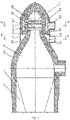
- The claimed device in one of the possible options of its implementation is shown in the following figures.
-
Figure 1 schematically shows one of the possible implementations of the shaftless air heater in the longitudinal section. -
Figure 2 and Figure 3 show the same in the cross section. - The claimed shaftless air heater has a burner located at the top in a pre-chamber 1 having a mushroom shape with a cavity representing a gas and air mixing chamber. The pre-chamber 1 has a shell 2 preferably made of low-alloy steel. The shell 2 of the pre-chamber 1 is made with the refractory lining which is made of light-weight refractory on the internal side of the shell 2. From the side of the gas and air mixing chamber the pre-chamber refractory lining is made of heat-resistant refractory with formation of an annular channel which is limited by an inside annular wall 3 and an outside annular wall 4. The refractory lining of the pre-chamber 1 is supported by a metal annular beam 5 made of low-alloy steel and having a shape of a right-angled triangle in its section, wherein one side of the triangle serves as an extension of the shell 2 of the pre-chamber 1, the other side is formed by a shell 7 of a dome-like combustion chamber 6 and the base is represented by a pre-chamber support. Under the pre-chamber 1 there is a combustion chamber 6 which has a dome-like upper part located coaxially with the pre-chamber 1, intercommunicates with it and is provided with the shell 7 made preferably of low-alloy steel with lining 8 made of a refractory material. In the interface area between the pre-chamber 1 and combustion chamber 6, the shell 2 of the pre-chamber 1 base has a diameter exceeding the diameter of the shell 7 of the dome-like part of the combustion chamber 6. The metal annular beam 5 is irremovably connected with the shells 2 and 7, for example, by welding and it is provided from the top with a base plate 9 forming an internal chamber with a cavity performing a function of air collector 10. Under the combustion chamber 6 there is a checkerwork chamber 11 with refractory checkerwork (not shown) made of preferably hexagonal checker bricks with holes laid in layers in such a way that the holes of the checker bricks laid in layers could provide passing of combustion products and heat transfer. In the outside annular wall 4 of the pre-chamber 1 there is an opening with a gas supply branch pipe 18 and between the inside annular wall 3 and outside annular wall 4 there is an annular channel for gas supply which performs a function of a gas collector 12. In the upper part of the inside annular wall 3 there are outlet openings 13 located in several rows which provide movement of gas in the form of swirling flows in the mixing chamber for which purpose the centerlines of the said openings have an angle of slope from 15 to 45° downwards to the horizontal plane, thereby creating an efficient swirling flow of gas in the central part of the mixing chamber. In the lower part of the inside annular wall 3 there are air openings 14 for air supply to the mixing chamber of the pre-chamber 1 and the centerlines of the said openings have an angle of slope from 0 to 45° upwards to the vertical plane. The swirling flows of air going from the openings 14 upwards at an angle meet in the mixing chamber of the pre-chamber 1 with the swirling flows of gas going from the outlet gas openings 13 downwards at an angle and mix with them in the mixing chamber of the pre-chamber 1 forming a homogeneous fuel mixture, thereby providing complete combustion of the above mentioned mixture. In the side wall of the air collector 10 there is an opening with an air supply branch pipe 15 into the air collector 10. The outlet air openings 14 into the mixing chamber located in the lower part of the inside annular wall 3 intercommunicate with the air collector 10 through air channels 16 connected with air openings 17 in the base plate 9. The intercommunicating pre-chamber 1 and gas and air mixture combustion chamber 6 are located coaxially which together with the gas collector 12 and air collector 10 form a burner system of the claimed air heater in the upper part of which there is a burner system represented by the pre-chamber 2 the cavity of which is a gas and air mixing chamber.
- The claimed shaftless air heater is operated as indicated below. In the cavity of the pre-chamber 1 representing a gas and air mixing chamber there occurs mixing of gas and air flows going respectively from the gas collector 12 and air supply channels 16 intercommunicating with the air collector 10 through the gas supply branch pipe 18 and air supply branch 15 where gas and air are supplied under pressure from the outside. The fuel mixture is formed due to mixing of swirling flows going from the outlet gas openings 13 and outlet air openings 14 into the mixing chamber with further inflammation and combustion of the formed gas and air mixture in the dome-like part of the combustion chamber 6. The resulting combustion chamber are supplied from the combustion chamber 6 to the checkerwork chamber 11.
- The burner system of the claimed air heater formed by the intercommunicating pre-chamber 1 and the combustion chamber 6 is characterized by spatial separation of the gas collector 12 and air collector 10 relative to each other. This separation of the gas and air flows in the burner system as well as location of the air collector in the cavity formed by the pre-chamber support which is the most stressed area of the air heater, provide a high efficiency of gas and air mixing and complete combustion of the resulting gas and air mixture as well as safe controlled operation of gas and air supply areas. This assuredly excludes uncontrolled mixing of gas and air in the pre-chamber of the burner system, eliminates danger of inflammation or explosion of the mixture and provides complete combustion of gas during fully safe operation of the air heater. Furthermore, the use of the metal annular beam for pre-chamber support and location an annular collector therein enables to decrease dimensions due to a decreased height of the air heater, reduce capital expenditures, thereby reducing its cost both during installation of a new air heater and reconstruction of an existing one.
Claims (6)
- Shaftless air heater, comprising a burner system with an annual gas collector and a pre-chamber the cavity of which represents a chamber for mixing, inflaming and initial combustion of gas and air flows; a chamber for combustion of the air-gas mixture coming from the pre-chamber having a dome-like shape in its upper part and located under the pre-chamber; a checkerwork chamber for passing of generated combustion products; the pre-chamber, combustion chamber and checkerwork chamber intercommunicate and are located coaxially, the pre-chamber and combustion chamber are equipped with their own lined shells, wherein the diameter of the pre-chamber shell base is bigger than the diameter of the dome-like combustion chamber shell throat, the gas collector represents an annular channel implemented in the pre-chamber refractory lining forming inside and outside annular walls; the mixing chamber intercommunicates with an annular air collector, outlet gas and air openings into the mixing chamber are made in the inside annular wall, the above mentioned outlet openings intercommunicate through the gas and air collectors with respective gas and air branch pipes from outside, characterized in that the air collector is located in the lower part of the pre-chamber under the gas collector and represents an annular chamber formed by the cavity between the metal annular beam and base plate installed at the base of the pre-chamber and connected to each other and to the pre-chamber and combustion chamber shells, wherein the metal annular beam forms a pre-chamber support and the base plate is provided with openings for air outlet from the air collector which intercommunicate through the air supply channels with the outlet air openings into the mixing chamber, wherein the outlet air openings being located in the inside annular wall under the outlet gas openings into the mixing chamber and the air supply channels being located in the lower part of the pre-chamber refractory lining.
- The shaftless air heater according to claim 1, characterized in that, in the burner system, the outlet gas openings from the gas collector into the mixing chamber are located in the inside annular wall at several levels.
- The shaftless air heater according to claim 1, characterized in that the centerlines of the outlet gas openings from the gas collector into the mixing chamber are provided at an angle of slope from 15 to 45° downwards to the horizontal plane.
- The shaftless air heater according to claim 1, characterized in that the centerlines of the outlet air openings from the air collector into the mixing chamber are provided at an angle of slope from 0 to 45° to the vertical plane.
- The shaftless air heater according to claim 1, characterized in that the metal annular beam is made of low-alloy steel.
- The shaftless air heater according to claim 1, characterized in that the metal annular beam has a shape of a right-angled triangle in its section, wherein one side of the triangle serves as an extension of the pre-chamber shell, the other side is formed by the shell of the dome-like combustion chamber and the base is represented by the pre-chamber support.
Applications Claiming Priority (2)
| Application Number | Priority Date | Filing Date | Title |
|---|---|---|---|
| RU2020119925A RU2753208C1 (en) | 2020-06-16 | 2020-06-16 | Shaftless air heater |
| PCT/RU2021/050166 WO2021256966A1 (en) | 2020-06-16 | 2021-06-15 | Shaftless air heater |
Publications (3)
| Publication Number | Publication Date |
|---|---|
| EP4023774A1 true EP4023774A1 (en) | 2022-07-06 |
| EP4023774A4 EP4023774A4 (en) | 2023-10-11 |
| EP4023774B1 EP4023774B1 (en) | 2025-08-06 |
Family
ID=77349014
Family Applications (1)
| Application Number | Title | Priority Date | Filing Date |
|---|---|---|---|
| EP21826662.5A Active EP4023774B1 (en) | 2020-06-16 | 2021-06-15 | Shaftless air heater |
Country Status (7)
| Country | Link |
|---|---|
| EP (1) | EP4023774B1 (en) |
| JP (1) | JP7351010B2 (en) |
| KR (1) | KR20220059520A (en) |
| CN (1) | CN115917012B (en) |
| BR (1) | BR112022010928A2 (en) |
| RU (1) | RU2753208C1 (en) |
| WO (1) | WO2021256966A1 (en) |
Families Citing this family (1)
| Publication number | Priority date | Publication date | Assignee | Title |
|---|---|---|---|---|
| CN115074476A (en) * | 2022-06-17 | 2022-09-20 | 河南省豫兴热风炉工程技术有限公司 | Burner with external gas ring pipe and air ring pipe on wall |
Family Cites Families (19)
| Publication number | Priority date | Publication date | Assignee | Title |
|---|---|---|---|---|
| US3473794A (en) | 1966-01-10 | 1969-10-21 | Smidth & Co As F L | System and method of producing cement clinker |
| DE1526029B1 (en) * | 1966-05-13 | 1971-04-22 | Martin & Pagenstecher Ag | BURNER EQUIPMENT FOR CHAMBERLESS WINDER HEATERS HEATERED FROM ABOVE |
| RU2145637C1 (en) * | 1999-03-29 | 2000-02-20 | Калугин Яков Прокопьевич | Air heater |
| RU2215792C1 (en) * | 2002-02-18 | 2003-11-10 | Калугин Яков Прокопьевич | Air heater |
| CN2717968Y (en) * | 2004-07-13 | 2005-08-17 | 山东省冶金设计院 | Top combustion stove with heat insulating layer on top combustion chamber |
| RU2316600C2 (en) * | 2006-03-01 | 2008-02-10 | Яков Прокопьевич Калугин | Air heater |
| CN101707893B (en) * | 2007-07-09 | 2012-04-18 | 雅科夫·普罗科皮耶维奇·卡卢金 | Hot stove |
| RU69069U1 (en) * | 2007-09-17 | 2007-12-10 | Виктор Васильевич Яковлев | AIR HEATER |
| UA35641U (en) * | 2008-05-12 | 2008-09-25 | Государственное Предприятие "Украинский Институт По Проектированию Металлургических Заводов" | Mehod for heating blast-furnace blast in mineless stove |
| CN201288198Y (en) | 2008-11-04 | 2009-08-12 | 首钢总公司 | Multi-contact circle rotational flow top burning hot blast stove |
| CN101408310A (en) * | 2008-11-27 | 2009-04-15 | 河南省豫兴热风炉工程技术有限公司 | Nozzle annular staggered-arranged combustor of eddy flow injection precombustion chamber |
| RU2554239C1 (en) | 2013-12-18 | 2015-06-27 | Закрытое Акционерное Общество "Калугин" | Shaftless air heater |
| CN104805246B (en) | 2015-04-21 | 2017-04-26 | 陈维汉 | Flow equalizing hot blast heater with premix air flow nozzle interconnection and air supply flow curved flowing |
| EP3173696A1 (en) * | 2015-11-30 | 2017-05-31 | Paul Wurth S.A. | Top combustion stove |
| RU193758U1 (en) | 2016-11-04 | 2019-11-13 | Чжэнчжоу Аннек Индастриал Ко., Лтд | UPPER HEATER OF THE NEW MODEL COMBUSTION LOCATION UP |
| CN207062313U (en) * | 2017-08-16 | 2018-03-02 | 中冶京诚工程技术有限公司 | A top-fired hot blast stove burner |
| CN108870738A (en) * | 2018-07-26 | 2018-11-23 | 江阴天田容器制造有限公司 | A kind of hot-blast stove |
| CN209495326U (en) * | 2019-01-30 | 2019-10-15 | 郑州豫兴热风炉科技有限公司 | A kind of top combustion stove of double air intake swirl injection burners |
| CN209836216U (en) | 2019-03-11 | 2019-12-24 | 山东省冶金设计院股份有限公司 | Top combustion hot blast stove with central uniform distribution type burner |
-
2020
- 2020-06-16 RU RU2020119925A patent/RU2753208C1/en active
-
2021
- 2021-06-15 BR BR112022010928A patent/BR112022010928A2/en unknown
- 2021-06-15 KR KR1020227011383A patent/KR20220059520A/en not_active Ceased
- 2021-06-15 JP JP2022528606A patent/JP7351010B2/en active Active
- 2021-06-15 EP EP21826662.5A patent/EP4023774B1/en active Active
- 2021-06-15 WO PCT/RU2021/050166 patent/WO2021256966A1/en not_active Ceased
- 2021-06-15 CN CN202180042430.8A patent/CN115917012B/en active Active
Also Published As
| Publication number | Publication date |
|---|---|
| JP2023502104A (en) | 2023-01-20 |
| CN115917012B (en) | 2026-02-17 |
| WO2021256966A1 (en) | 2021-12-23 |
| RU2753208C1 (en) | 2021-08-12 |
| BR112022010928A2 (en) | 2022-12-27 |
| CN115917012A (en) | 2023-04-04 |
| JP7351010B2 (en) | 2023-09-26 |
| EP4023774A4 (en) | 2023-10-11 |
| KR20220059520A (en) | 2022-05-10 |
| EP4023774B1 (en) | 2025-08-06 |
Similar Documents
| Publication | Publication Date | Title |
|---|---|---|
| EP2177633B1 (en) | Air heater | |
| RU2215792C1 (en) | Air heater | |
| EP4023774B1 (en) | Shaftless air heater | |
| US4140480A (en) | Hot cupola gas burner | |
| CN202125949U (en) | Efficient combustor | |
| CN220707332U (en) | Porous medium combustor and heating furnace | |
| US3411761A (en) | Burner and soaking pit | |
| RU2316600C2 (en) | Air heater | |
| CN217654102U (en) | Vertical hot blast furnace system with low nitrogen oxide emission | |
| CN216845660U (en) | Novel multi-fuel high-temperature flue gas fluidized bed furnace | |
| EA045173B1 (en) | LIGHT-FREE AIR HEATER | |
| US4132394A (en) | Furnaces | |
| CN212252685U (en) | Flue type heating furnace | |
| JPH07218142A (en) | Radiant heating device and combustion method thereof | |
| US3732070A (en) | Burner | |
| CN219735615U (en) | Yellow phosphorus tail gas burning hot air production device | |
| US2505861A (en) | Regenerative hot-blast system | |
| CN224033805U (en) | Process burner and reaction furnace | |
| CN219112884U (en) | Integrated pure oxygen combustion baking device | |
| CN221172594U (en) | Polyester heating medium boiler of natural gas fuel | |
| RU201414U1 (en) | REMOTE FURNACE FOR OBTAINING GASEOUS COOLANT BY COMBUSTION OF GASEOUS FUEL | |
| CN111266063B (en) | A heating system for acid regeneration | |
| CN120174166A (en) | Top-burning hot air stove | |
| CN121430012A (en) | An integrated heating device for hydrogen-rich fuel gas used in blast furnaces | |
| SU1252818A1 (en) | Device for drying blast-furnace bottom |
Legal Events
| Date | Code | Title | Description |
|---|---|---|---|
| STAA | Information on the status of an ep patent application or granted ep patent |
Free format text: STATUS: THE INTERNATIONAL PUBLICATION HAS BEEN MADE |
|
| PUAI | Public reference made under article 153(3) epc to a published international application that has entered the european phase |
Free format text: ORIGINAL CODE: 0009012 |
|
| STAA | Information on the status of an ep patent application or granted ep patent |
Free format text: STATUS: REQUEST FOR EXAMINATION WAS MADE |
|
| 17P | Request for examination filed |
Effective date: 20220330 |
|
| AK | Designated contracting states |
Kind code of ref document: A1 Designated state(s): AL AT BE BG CH CY CZ DE DK EE ES FI FR GB GR HR HU IE IS IT LI LT LU LV MC MK MT NL NO PL PT RO RS SE SI SK SM TR |
|
| TPAC | Observations filed by third parties |
Free format text: ORIGINAL CODE: EPIDOSNTIPA |
|
| DAV | Request for validation of the european patent (deleted) | ||
| DAX | Request for extension of the european patent (deleted) | ||
| A4 | Supplementary search report drawn up and despatched |
Effective date: 20230908 |
|
| RIC1 | Information provided on ipc code assigned before grant |
Ipc: F24H 3/00 20220101ALI20230904BHEP Ipc: C21B 9/00 20060101AFI20230904BHEP |
|
| GRAP | Despatch of communication of intention to grant a patent |
Free format text: ORIGINAL CODE: EPIDOSNIGR1 |
|
| STAA | Information on the status of an ep patent application or granted ep patent |
Free format text: STATUS: GRANT OF PATENT IS INTENDED |
|
| INTG | Intention to grant announced |
Effective date: 20250129 |
|
| GRAS | Grant fee paid |
Free format text: ORIGINAL CODE: EPIDOSNIGR3 |
|
| GRAA | (expected) grant |
Free format text: ORIGINAL CODE: 0009210 |
|
| STAA | Information on the status of an ep patent application or granted ep patent |
Free format text: STATUS: THE PATENT HAS BEEN GRANTED |
|
| AK | Designated contracting states |
Kind code of ref document: B1 Designated state(s): AL AT BE BG CH CY CZ DE DK EE ES FI FR GB GR HR HU IE IS IT LI LT LU LV MC MK MT NL NO PL PT RO RS SE SI SK SM TR |
|
| REG | Reference to a national code |
Ref country code: GB Ref legal event code: FG4D |
|
| REG | Reference to a national code |
Ref country code: CH Ref legal event code: EP |
|
| REG | Reference to a national code |
Ref country code: IE Ref legal event code: FG4D |
|
| REG | Reference to a national code |
Ref country code: DE Ref legal event code: R096 Ref document number: 602021035788 Country of ref document: DE |
|
| REG | Reference to a national code |
Ref country code: NL Ref legal event code: MP Effective date: 20250806 |
|
| PG25 | Lapsed in a contracting state [announced via postgrant information from national office to epo] |
Ref country code: IS Free format text: LAPSE BECAUSE OF FAILURE TO SUBMIT A TRANSLATION OF THE DESCRIPTION OR TO PAY THE FEE WITHIN THE PRESCRIBED TIME-LIMIT Effective date: 20251206 |
|
| PG25 | Lapsed in a contracting state [announced via postgrant information from national office to epo] |
Ref country code: NO Free format text: LAPSE BECAUSE OF FAILURE TO SUBMIT A TRANSLATION OF THE DESCRIPTION OR TO PAY THE FEE WITHIN THE PRESCRIBED TIME-LIMIT Effective date: 20251106 |
|
| REG | Reference to a national code |
Ref country code: LT Ref legal event code: MG9D |
|
| PG25 | Lapsed in a contracting state [announced via postgrant information from national office to epo] |
Ref country code: PT Free format text: LAPSE BECAUSE OF FAILURE TO SUBMIT A TRANSLATION OF THE DESCRIPTION OR TO PAY THE FEE WITHIN THE PRESCRIBED TIME-LIMIT Effective date: 20251209 |
|
| PG25 | Lapsed in a contracting state [announced via postgrant information from national office to epo] |
Ref country code: FI Free format text: LAPSE BECAUSE OF FAILURE TO SUBMIT A TRANSLATION OF THE DESCRIPTION OR TO PAY THE FEE WITHIN THE PRESCRIBED TIME-LIMIT Effective date: 20250806 |
|
| PG25 | Lapsed in a contracting state [announced via postgrant information from national office to epo] |
Ref country code: HR Free format text: LAPSE BECAUSE OF FAILURE TO SUBMIT A TRANSLATION OF THE DESCRIPTION OR TO PAY THE FEE WITHIN THE PRESCRIBED TIME-LIMIT Effective date: 20250806 Ref country code: NL Free format text: LAPSE BECAUSE OF FAILURE TO SUBMIT A TRANSLATION OF THE DESCRIPTION OR TO PAY THE FEE WITHIN THE PRESCRIBED TIME-LIMIT Effective date: 20250806 |
|
| PG25 | Lapsed in a contracting state [announced via postgrant information from national office to epo] |
Ref country code: GR Free format text: LAPSE BECAUSE OF FAILURE TO SUBMIT A TRANSLATION OF THE DESCRIPTION OR TO PAY THE FEE WITHIN THE PRESCRIBED TIME-LIMIT Effective date: 20251107 |
|
| PG25 | Lapsed in a contracting state [announced via postgrant information from national office to epo] |
Ref country code: SE Free format text: LAPSE BECAUSE OF FAILURE TO SUBMIT A TRANSLATION OF THE DESCRIPTION OR TO PAY THE FEE WITHIN THE PRESCRIBED TIME-LIMIT Effective date: 20250806 |
|
| PG25 | Lapsed in a contracting state [announced via postgrant information from national office to epo] |
Ref country code: LV Free format text: LAPSE BECAUSE OF FAILURE TO SUBMIT A TRANSLATION OF THE DESCRIPTION OR TO PAY THE FEE WITHIN THE PRESCRIBED TIME-LIMIT Effective date: 20250806 |
|
| PG25 | Lapsed in a contracting state [announced via postgrant information from national office to epo] |
Ref country code: BG Free format text: LAPSE BECAUSE OF FAILURE TO SUBMIT A TRANSLATION OF THE DESCRIPTION OR TO PAY THE FEE WITHIN THE PRESCRIBED TIME-LIMIT Effective date: 20250806 Ref country code: PL Free format text: LAPSE BECAUSE OF FAILURE TO SUBMIT A TRANSLATION OF THE DESCRIPTION OR TO PAY THE FEE WITHIN THE PRESCRIBED TIME-LIMIT Effective date: 20250806 |
|
| PG25 | Lapsed in a contracting state [announced via postgrant information from national office to epo] |
Ref country code: RS Free format text: LAPSE BECAUSE OF FAILURE TO SUBMIT A TRANSLATION OF THE DESCRIPTION OR TO PAY THE FEE WITHIN THE PRESCRIBED TIME-LIMIT Effective date: 20251106 |
|
| PG25 | Lapsed in a contracting state [announced via postgrant information from national office to epo] |
Ref country code: ES Free format text: LAPSE BECAUSE OF FAILURE TO SUBMIT A TRANSLATION OF THE DESCRIPTION OR TO PAY THE FEE WITHIN THE PRESCRIBED TIME-LIMIT Effective date: 20250806 |
|
| REG | Reference to a national code |
Ref country code: AT Ref legal event code: MK05 Ref document number: 1821890 Country of ref document: AT Kind code of ref document: T Effective date: 20250806 |
|
| PG25 | Lapsed in a contracting state [announced via postgrant information from national office to epo] |
Ref country code: SM Free format text: LAPSE BECAUSE OF FAILURE TO SUBMIT A TRANSLATION OF THE DESCRIPTION OR TO PAY THE FEE WITHIN THE PRESCRIBED TIME-LIMIT Effective date: 20250806 |
|
| PG25 | Lapsed in a contracting state [announced via postgrant information from national office to epo] |
Ref country code: DK Free format text: LAPSE BECAUSE OF FAILURE TO SUBMIT A TRANSLATION OF THE DESCRIPTION OR TO PAY THE FEE WITHIN THE PRESCRIBED TIME-LIMIT Effective date: 20250806 |
|
| PG25 | Lapsed in a contracting state [announced via postgrant information from national office to epo] |
Ref country code: AT Free format text: LAPSE BECAUSE OF FAILURE TO SUBMIT A TRANSLATION OF THE DESCRIPTION OR TO PAY THE FEE WITHIN THE PRESCRIBED TIME-LIMIT Effective date: 20250806 |
|
| PG25 | Lapsed in a contracting state [announced via postgrant information from national office to epo] |
Ref country code: IT Free format text: LAPSE BECAUSE OF FAILURE TO SUBMIT A TRANSLATION OF THE DESCRIPTION OR TO PAY THE FEE WITHIN THE PRESCRIBED TIME-LIMIT Effective date: 20250806 |
|
| PG25 | Lapsed in a contracting state [announced via postgrant information from national office to epo] |
Ref country code: CZ Free format text: LAPSE BECAUSE OF FAILURE TO SUBMIT A TRANSLATION OF THE DESCRIPTION OR TO PAY THE FEE WITHIN THE PRESCRIBED TIME-LIMIT Effective date: 20250806 |
|
| PG25 | Lapsed in a contracting state [announced via postgrant information from national office to epo] |
Ref country code: SK Free format text: LAPSE BECAUSE OF FAILURE TO SUBMIT A TRANSLATION OF THE DESCRIPTION OR TO PAY THE FEE WITHIN THE PRESCRIBED TIME-LIMIT Effective date: 20250806 Ref country code: EE Free format text: LAPSE BECAUSE OF FAILURE TO SUBMIT A TRANSLATION OF THE DESCRIPTION OR TO PAY THE FEE WITHIN THE PRESCRIBED TIME-LIMIT Effective date: 20250806 |
|
| REG | Reference to a national code |
Ref country code: DE Ref legal event code: R097 Ref document number: 602021035788 Country of ref document: DE |
|
| PLBE | No opposition filed within time limit |
Free format text: ORIGINAL CODE: 0009261 |
|
| STAA | Information on the status of an ep patent application or granted ep patent |
Free format text: STATUS: NO OPPOSITION FILED WITHIN TIME LIMIT |
|
| REG | Reference to a national code |
Ref country code: CH Ref legal event code: L10 Free format text: ST27 STATUS EVENT CODE: U-0-0-L10-L00 (AS PROVIDED BY THE NATIONAL OFFICE) Effective date: 20260617 |
|
| PG25 | Lapsed in a contracting state [announced via postgrant information from national office to epo] |
Ref country code: LT Free format text: LAPSE BECAUSE OF FAILURE TO SUBMIT A TRANSLATION OF THE DESCRIPTION OR TO PAY THE FEE WITHIN THE PRESCRIBED TIME-LIMIT Effective date: 20250806 |
|
| 26N | No opposition filed |
Effective date: 20260507 |