EP4023621A1 - Yag ceramic joined body and production method therefor - Google Patents
Yag ceramic joined body and production method therefor Download PDFInfo
- Publication number
- EP4023621A1 EP4023621A1 EP20917282.4A EP20917282A EP4023621A1 EP 4023621 A1 EP4023621 A1 EP 4023621A1 EP 20917282 A EP20917282 A EP 20917282A EP 4023621 A1 EP4023621 A1 EP 4023621A1
- Authority
- EP
- European Patent Office
- Prior art keywords
- yag
- yag ceramic
- ceramic
- glass
- bonded
- Prior art date
- Legal status (The legal status is an assumption and is not a legal conclusion. Google has not performed a legal analysis and makes no representation as to the accuracy of the status listed.)
- Pending
Links
Images

Classifications
-
- C—CHEMISTRY; METALLURGY
- C04—CEMENTS; CONCRETE; ARTIFICIAL STONE; CERAMICS; REFRACTORIES
- C04B—LIME, MAGNESIA; SLAG; CEMENTS; COMPOSITIONS THEREOF, e.g. MORTARS, CONCRETE OR LIKE BUILDING MATERIALS; ARTIFICIAL STONE; CERAMICS; REFRACTORIES; TREATMENT OF NATURAL STONE
- C04B37/00—Joining burned ceramic articles with other burned ceramic articles or other articles by heating
- C04B37/003—Joining burned ceramic articles with other burned ceramic articles or other articles by heating by means of an interlayer consisting of a combination of materials selected from glass, or ceramic material with metals, metal oxides or metal salts
-
- H—ELECTRICITY
- H01—ELECTRIC ELEMENTS
- H01S—DEVICES USING THE PROCESS OF LIGHT AMPLIFICATION BY STIMULATED EMISSION OF RADIATION [LASER] TO AMPLIFY OR GENERATE LIGHT; DEVICES USING STIMULATED EMISSION OF ELECTROMAGNETIC RADIATION IN WAVE RANGES OTHER THAN OPTICAL
- H01S3/00—Lasers, i.e. devices using stimulated emission of electromagnetic radiation in the infrared, visible or ultraviolet wave range
- H01S3/05—Construction or shape of optical resonators; Accommodation of active medium therein; Shape of active medium
- H01S3/06—Construction or shape of active medium
- H01S3/0602—Crystal lasers or glass lasers
- H01S3/0612—Non-homogeneous structure
-
- H—ELECTRICITY
- H01—ELECTRIC ELEMENTS
- H01S—DEVICES USING THE PROCESS OF LIGHT AMPLIFICATION BY STIMULATED EMISSION OF RADIATION [LASER] TO AMPLIFY OR GENERATE LIGHT; DEVICES USING STIMULATED EMISSION OF ELECTROMAGNETIC RADIATION IN WAVE RANGES OTHER THAN OPTICAL
- H01S3/00—Lasers, i.e. devices using stimulated emission of electromagnetic radiation in the infrared, visible or ultraviolet wave range
- H01S3/14—Lasers, i.e. devices using stimulated emission of electromagnetic radiation in the infrared, visible or ultraviolet wave range characterised by the material used as the active medium
- H01S3/16—Solid materials
- H01S3/163—Solid materials characterised by a crystal matrix
- H01S3/164—Solid materials characterised by a crystal matrix garnet
- H01S3/1643—YAG
-
- C—CHEMISTRY; METALLURGY
- C04—CEMENTS; CONCRETE; ARTIFICIAL STONE; CERAMICS; REFRACTORIES
- C04B—LIME, MAGNESIA; SLAG; CEMENTS; COMPOSITIONS THEREOF, e.g. MORTARS, CONCRETE OR LIKE BUILDING MATERIALS; ARTIFICIAL STONE; CERAMICS; REFRACTORIES; TREATMENT OF NATURAL STONE
- C04B37/00—Joining burned ceramic articles with other burned ceramic articles or other articles by heating
- C04B37/001—Joining burned ceramic articles with other burned ceramic articles or other articles by heating directly with other burned ceramic articles
-
- C—CHEMISTRY; METALLURGY
- C04—CEMENTS; CONCRETE; ARTIFICIAL STONE; CERAMICS; REFRACTORIES
- C04B—LIME, MAGNESIA; SLAG; CEMENTS; COMPOSITIONS THEREOF, e.g. MORTARS, CONCRETE OR LIKE BUILDING MATERIALS; ARTIFICIAL STONE; CERAMICS; REFRACTORIES; TREATMENT OF NATURAL STONE
- C04B37/00—Joining burned ceramic articles with other burned ceramic articles or other articles by heating
- C04B37/003—Joining burned ceramic articles with other burned ceramic articles or other articles by heating by means of an interlayer consisting of a combination of materials selected from glass, or ceramic material with metals, metal oxides or metal salts
- C04B37/005—Joining burned ceramic articles with other burned ceramic articles or other articles by heating by means of an interlayer consisting of a combination of materials selected from glass, or ceramic material with metals, metal oxides or metal salts consisting of glass or ceramic material
-
- C—CHEMISTRY; METALLURGY
- C04—CEMENTS; CONCRETE; ARTIFICIAL STONE; CERAMICS; REFRACTORIES
- C04B—LIME, MAGNESIA; SLAG; CEMENTS; COMPOSITIONS THEREOF, e.g. MORTARS, CONCRETE OR LIKE BUILDING MATERIALS; ARTIFICIAL STONE; CERAMICS; REFRACTORIES; TREATMENT OF NATURAL STONE
- C04B37/00—Joining burned ceramic articles with other burned ceramic articles or other articles by heating
- C04B37/04—Joining burned ceramic articles with other burned ceramic articles or other articles by heating with articles made from glass
- C04B37/045—Joining burned ceramic articles with other burned ceramic articles or other articles by heating with articles made from glass characterised by the interlayer used
-
- H—ELECTRICITY
- H01—ELECTRIC ELEMENTS
- H01S—DEVICES USING THE PROCESS OF LIGHT AMPLIFICATION BY STIMULATED EMISSION OF RADIATION [LASER] TO AMPLIFY OR GENERATE LIGHT; DEVICES USING STIMULATED EMISSION OF ELECTROMAGNETIC RADIATION IN WAVE RANGES OTHER THAN OPTICAL
- H01S3/00—Lasers, i.e. devices using stimulated emission of electromagnetic radiation in the infrared, visible or ultraviolet wave range
- H01S3/05—Construction or shape of optical resonators; Accommodation of active medium therein; Shape of active medium
- H01S3/06—Construction or shape of active medium
-
- H—ELECTRICITY
- H01—ELECTRIC ELEMENTS
- H01S—DEVICES USING THE PROCESS OF LIGHT AMPLIFICATION BY STIMULATED EMISSION OF RADIATION [LASER] TO AMPLIFY OR GENERATE LIGHT; DEVICES USING STIMULATED EMISSION OF ELECTROMAGNETIC RADIATION IN WAVE RANGES OTHER THAN OPTICAL
- H01S3/00—Lasers, i.e. devices using stimulated emission of electromagnetic radiation in the infrared, visible or ultraviolet wave range
- H01S3/05—Construction or shape of optical resonators; Accommodation of active medium therein; Shape of active medium
- H01S3/06—Construction or shape of active medium
- H01S3/0602—Crystal lasers or glass lasers
- H01S3/0606—Crystal lasers or glass lasers with polygonal cross-section, e.g. slab, prism
-
- H—ELECTRICITY
- H01—ELECTRIC ELEMENTS
- H01S—DEVICES USING THE PROCESS OF LIGHT AMPLIFICATION BY STIMULATED EMISSION OF RADIATION [LASER] TO AMPLIFY OR GENERATE LIGHT; DEVICES USING STIMULATED EMISSION OF ELECTROMAGNETIC RADIATION IN WAVE RANGES OTHER THAN OPTICAL
- H01S3/00—Lasers, i.e. devices using stimulated emission of electromagnetic radiation in the infrared, visible or ultraviolet wave range
- H01S3/05—Construction or shape of optical resonators; Accommodation of active medium therein; Shape of active medium
- H01S3/06—Construction or shape of active medium
- H01S3/0602—Crystal lasers or glass lasers
- H01S3/0617—Crystal lasers or glass lasers having a varying composition or cross-section in a specific direction
-
- H—ELECTRICITY
- H01—ELECTRIC ELEMENTS
- H01S—DEVICES USING THE PROCESS OF LIGHT AMPLIFICATION BY STIMULATED EMISSION OF RADIATION [LASER] TO AMPLIFY OR GENERATE LIGHT; DEVICES USING STIMULATED EMISSION OF ELECTROMAGNETIC RADIATION IN WAVE RANGES OTHER THAN OPTICAL
- H01S3/00—Lasers, i.e. devices using stimulated emission of electromagnetic radiation in the infrared, visible or ultraviolet wave range
- H01S3/05—Construction or shape of optical resonators; Accommodation of active medium therein; Shape of active medium
- H01S3/06—Construction or shape of active medium
- H01S3/0619—Coatings, e.g. AR, HR, passivation layer
-
- H—ELECTRICITY
- H01—ELECTRIC ELEMENTS
- H01S—DEVICES USING THE PROCESS OF LIGHT AMPLIFICATION BY STIMULATED EMISSION OF RADIATION [LASER] TO AMPLIFY OR GENERATE LIGHT; DEVICES USING STIMULATED EMISSION OF ELECTROMAGNETIC RADIATION IN WAVE RANGES OTHER THAN OPTICAL
- H01S3/00—Lasers, i.e. devices using stimulated emission of electromagnetic radiation in the infrared, visible or ultraviolet wave range
- H01S3/05—Construction or shape of optical resonators; Accommodation of active medium therein; Shape of active medium
- H01S3/06—Construction or shape of active medium
- H01S3/0619—Coatings, e.g. AR, HR, passivation layer
- H01S3/0625—Coatings on surfaces other than the end-faces
-
- H—ELECTRICITY
- H01—ELECTRIC ELEMENTS
- H01S—DEVICES USING THE PROCESS OF LIGHT AMPLIFICATION BY STIMULATED EMISSION OF RADIATION [LASER] TO AMPLIFY OR GENERATE LIGHT; DEVICES USING STIMULATED EMISSION OF ELECTROMAGNETIC RADIATION IN WAVE RANGES OTHER THAN OPTICAL
- H01S3/00—Lasers, i.e. devices using stimulated emission of electromagnetic radiation in the infrared, visible or ultraviolet wave range
- H01S3/14—Lasers, i.e. devices using stimulated emission of electromagnetic radiation in the infrared, visible or ultraviolet wave range characterised by the material used as the active medium
- H01S3/16—Solid materials
- H01S3/1685—Ceramics
-
- C—CHEMISTRY; METALLURGY
- C04—CEMENTS; CONCRETE; ARTIFICIAL STONE; CERAMICS; REFRACTORIES
- C04B—LIME, MAGNESIA; SLAG; CEMENTS; COMPOSITIONS THEREOF, e.g. MORTARS, CONCRETE OR LIKE BUILDING MATERIALS; ARTIFICIAL STONE; CERAMICS; REFRACTORIES; TREATMENT OF NATURAL STONE
- C04B2235/00—Aspects relating to ceramic starting mixtures or sintered ceramic products
- C04B2235/02—Composition of constituents of the starting material or of secondary phases of the final product
- C04B2235/30—Constituents and secondary phases not being of a fibrous nature
- C04B2235/32—Metal oxides, mixed metal oxides, or oxide-forming salts thereof, e.g. carbonates, nitrates, (oxy)hydroxides, chlorides
- C04B2235/3217—Aluminum oxide or oxide forming salts thereof, e.g. bauxite, alpha-alumina
- C04B2235/3222—Aluminates other than alumino-silicates, e.g. spinel (MgAl2O4)
-
- C—CHEMISTRY; METALLURGY
- C04—CEMENTS; CONCRETE; ARTIFICIAL STONE; CERAMICS; REFRACTORIES
- C04B—LIME, MAGNESIA; SLAG; CEMENTS; COMPOSITIONS THEREOF, e.g. MORTARS, CONCRETE OR LIKE BUILDING MATERIALS; ARTIFICIAL STONE; CERAMICS; REFRACTORIES; TREATMENT OF NATURAL STONE
- C04B2235/00—Aspects relating to ceramic starting mixtures or sintered ceramic products
- C04B2235/02—Composition of constituents of the starting material or of secondary phases of the final product
- C04B2235/30—Constituents and secondary phases not being of a fibrous nature
- C04B2235/32—Metal oxides, mixed metal oxides, or oxide-forming salts thereof, e.g. carbonates, nitrates, (oxy)hydroxides, chlorides
- C04B2235/3224—Rare earth oxide or oxide forming salts thereof, e.g. scandium oxide
-
- C—CHEMISTRY; METALLURGY
- C04—CEMENTS; CONCRETE; ARTIFICIAL STONE; CERAMICS; REFRACTORIES
- C04B—LIME, MAGNESIA; SLAG; CEMENTS; COMPOSITIONS THEREOF, e.g. MORTARS, CONCRETE OR LIKE BUILDING MATERIALS; ARTIFICIAL STONE; CERAMICS; REFRACTORIES; TREATMENT OF NATURAL STONE
- C04B2235/00—Aspects relating to ceramic starting mixtures or sintered ceramic products
- C04B2235/02—Composition of constituents of the starting material or of secondary phases of the final product
- C04B2235/30—Constituents and secondary phases not being of a fibrous nature
- C04B2235/32—Metal oxides, mixed metal oxides, or oxide-forming salts thereof, e.g. carbonates, nitrates, (oxy)hydroxides, chlorides
- C04B2235/3224—Rare earth oxide or oxide forming salts thereof, e.g. scandium oxide
- C04B2235/3225—Yttrium oxide or oxide-forming salts thereof
-
- C—CHEMISTRY; METALLURGY
- C04—CEMENTS; CONCRETE; ARTIFICIAL STONE; CERAMICS; REFRACTORIES
- C04B—LIME, MAGNESIA; SLAG; CEMENTS; COMPOSITIONS THEREOF, e.g. MORTARS, CONCRETE OR LIKE BUILDING MATERIALS; ARTIFICIAL STONE; CERAMICS; REFRACTORIES; TREATMENT OF NATURAL STONE
- C04B2235/00—Aspects relating to ceramic starting mixtures or sintered ceramic products
- C04B2235/02—Composition of constituents of the starting material or of secondary phases of the final product
- C04B2235/30—Constituents and secondary phases not being of a fibrous nature
- C04B2235/32—Metal oxides, mixed metal oxides, or oxide-forming salts thereof, e.g. carbonates, nitrates, (oxy)hydroxides, chlorides
- C04B2235/3231—Refractory metal oxides, their mixed metal oxides, or oxide-forming salts thereof
- C04B2235/3241—Chromium oxides, chromates, or oxide-forming salts thereof
-
- C—CHEMISTRY; METALLURGY
- C04—CEMENTS; CONCRETE; ARTIFICIAL STONE; CERAMICS; REFRACTORIES
- C04B—LIME, MAGNESIA; SLAG; CEMENTS; COMPOSITIONS THEREOF, e.g. MORTARS, CONCRETE OR LIKE BUILDING MATERIALS; ARTIFICIAL STONE; CERAMICS; REFRACTORIES; TREATMENT OF NATURAL STONE
- C04B2235/00—Aspects relating to ceramic starting mixtures or sintered ceramic products
- C04B2235/70—Aspects relating to sintered or melt-casted ceramic products
- C04B2235/74—Physical characteristics
- C04B2235/76—Crystal structural characteristics, e.g. symmetry
- C04B2235/762—Cubic symmetry, e.g. beta-SiC
- C04B2235/764—Garnet structure A3B2(CO4)3
-
- C—CHEMISTRY; METALLURGY
- C04—CEMENTS; CONCRETE; ARTIFICIAL STONE; CERAMICS; REFRACTORIES
- C04B—LIME, MAGNESIA; SLAG; CEMENTS; COMPOSITIONS THEREOF, e.g. MORTARS, CONCRETE OR LIKE BUILDING MATERIALS; ARTIFICIAL STONE; CERAMICS; REFRACTORIES; TREATMENT OF NATURAL STONE
- C04B2235/00—Aspects relating to ceramic starting mixtures or sintered ceramic products
- C04B2235/70—Aspects relating to sintered or melt-casted ceramic products
- C04B2235/96—Properties of ceramic products, e.g. mechanical properties such as strength, toughness, wear resistance
- C04B2235/9607—Thermal properties, e.g. thermal expansion coefficient
-
- C—CHEMISTRY; METALLURGY
- C04—CEMENTS; CONCRETE; ARTIFICIAL STONE; CERAMICS; REFRACTORIES
- C04B—LIME, MAGNESIA; SLAG; CEMENTS; COMPOSITIONS THEREOF, e.g. MORTARS, CONCRETE OR LIKE BUILDING MATERIALS; ARTIFICIAL STONE; CERAMICS; REFRACTORIES; TREATMENT OF NATURAL STONE
- C04B2235/00—Aspects relating to ceramic starting mixtures or sintered ceramic products
- C04B2235/70—Aspects relating to sintered or melt-casted ceramic products
- C04B2235/96—Properties of ceramic products, e.g. mechanical properties such as strength, toughness, wear resistance
- C04B2235/9646—Optical properties
- C04B2235/9653—Translucent or transparent ceramics other than alumina
-
- C—CHEMISTRY; METALLURGY
- C04—CEMENTS; CONCRETE; ARTIFICIAL STONE; CERAMICS; REFRACTORIES
- C04B—LIME, MAGNESIA; SLAG; CEMENTS; COMPOSITIONS THEREOF, e.g. MORTARS, CONCRETE OR LIKE BUILDING MATERIALS; ARTIFICIAL STONE; CERAMICS; REFRACTORIES; TREATMENT OF NATURAL STONE
- C04B2237/00—Aspects relating to ceramic laminates or to joining of ceramic articles with other articles by heating
- C04B2237/02—Aspects relating to interlayers, e.g. used to join ceramic articles with other articles by heating
- C04B2237/10—Glass interlayers, e.g. frit or flux
-
- C—CHEMISTRY; METALLURGY
- C04—CEMENTS; CONCRETE; ARTIFICIAL STONE; CERAMICS; REFRACTORIES
- C04B—LIME, MAGNESIA; SLAG; CEMENTS; COMPOSITIONS THEREOF, e.g. MORTARS, CONCRETE OR LIKE BUILDING MATERIALS; ARTIFICIAL STONE; CERAMICS; REFRACTORIES; TREATMENT OF NATURAL STONE
- C04B2237/00—Aspects relating to ceramic laminates or to joining of ceramic articles with other articles by heating
- C04B2237/30—Composition of layers of ceramic laminates or of ceramic or metallic articles to be joined by heating, e.g. Si substrates
- C04B2237/32—Ceramic
- C04B2237/34—Oxidic
- C04B2237/343—Alumina or aluminates
Definitions
- the present invention generally relates to a YAG (yttrium-aluminum-garnet) ceramic bonded body, and particularly relates to a YAG ceramic bonded body in which glass is interposed as a bonding layer as well as to the production method thereof.
- YAG yttrium-aluminum-garnet
- a standard laser is an application which excites a laser medium, which is a phosphor, and optically amplifies the laser medium in a resonator which is sandwiched with optically opposing high reflectance mirrors.
- a laser medium which is a phosphor
- YAG ceramics are used as a representative example of a high-power laser medium.
- an amplifier which amplifies the laser beam output generated from a separate medium.
- Non-Patent Documents 1, 2 the development of light-absorbing layer YAG polycrystals in which the circumference of the Nd:YAG polycrystalline material is doped with Sm has been reported.
- high-power operation has been confirmed by bonding a Cr-doped polycrystalline body to a Yb:YAG laser polycrystalline body having superior energy storage (Non-Patent Document 3).
- the YAG ceramics are exclusively used for a high-power laser, and demanded is a technology for bonding a YAG ceramic of different dopants and light-absorbing optical glass, as a light-absorbing layer for preventing parasitic oscillation, to a YAG ceramic of the laser oscillation part.
- a technology for bonding a YAG ceramic and a YAG ceramic, or bonding a YAG ceramic and light-absorbing optical glass for satisfying the foregoing demands.
- Patent Document 1 Japanese Unexamined Patent Application Publication (Translation of PCT Application) No. 2014-519721
- the present invention was devised in view of the foregoing circumstances, and an object of this invention is to provide a bonded body in which a YAG ceramic and a YAG ceramic are bonded, or a bonded body in which a YAG ceramic and optical glass are bonded, and which is capable of suppressing the reflection of light at the bonded interface, as well as the production method thereof.
- an embodiment of the present invention is a YAG ceramic bonded body in which a YAG ceramic and a YAG ceramic or optical glass are bonded, wherein the YAG ceramic bonded body comprises glass as a bonding layer and has a rate of change of transmittance that is within 7%.
- the present invention it is possible to yield a superior effect of providing a bonded body of a YAG ceramic and a YAG ceramic, or a bonded body of a YAG ceramic and optical glass, in which the reflection of light at the bonded interface is suppressed.
- the bonding of a ceramic and a ceramic has been reported in the past, and this performed by flattening the surfaces to be bonded, applying pressure while applying temperature, and diffusion-bonding the ceramics based on their atomic diffusion.
- this diffusion bonding the surfaces to be bonded are polished into a mirror surface, and the temperature is increased in a state where the surfaces to be bonded are in contact so as to attain a diffusible state.
- the treatment based on diffusion bonding needs to be performed in a furnace of several hundred degrees to one thousand and several hundred degrees, positioning and sophisticated temperature control giving consideration to the thermal expansion of the ceramics are required, and it was difficult to perform bonding with in-plane uniformity. Furthermore, the foregoing treatment becomes even more difficult when the bonded surface area is increased.
- the normal temperature bonding method In recent years, as another method of bonding a ceramic and a ceramic, the normal temperature bonding method has been reported.
- the object to be bonded In normal temperature bonding, the object to be bonded is placed in a vacuum chamber, and the contact surface is irradiated with an atom beam or an ion beam such as an Ar beam. On the irradiated surface, the surface bond of the elements will become exposed, and, as a result of causing the surfaces to be bonded to contact each other, a strong bond can thereby be created even at normal temperature without elemental diffusion.
- an optical adhesive generally has a high coefficient of thermal expansion, and there is a problem in that the strain will increase when the temperature is changed.
- the main component of the adhesive is an organic material, there is a problem in that the heat resistance (cold resistance) properties are inferior.
- the heat resistance (cold resistance) properties and light resistance properties of organic skeletal components will deteriorate.
- nanoparticles are also sometimes included in the adhesive in order to adjust the refractive index, there is concern that the bonding strength may deteriorate depending on the amount of nanoparticles that is included.
- the present inventors took particular note of bonding using a glass material. Since glass is a material having considerable formativeness; that is, combined properties of a solid nature having elasticity at room temperature and a liquid nature having fluidity when the temperature is increased, it is a material with a broad range of material formation.
- the present invention is characterized in using this kind of glass as a bonding layer, and having prepared a bonded body of a YAG ceramic and a YAG ceramic, or a bonded body of a YAG ceramic and another optical material (optical glass).
- a YAG ceramic bonded body which uses glass as the bonding layer has high transmittance and suppressed light reflection at the bonded interface, and is extremely useful in laser applications.
- the ceramic bonded body according to this embodiment is a YAG ceramic bonded body in which a YAG ceramic and a YAG ceramic or optical glass are bonded, wherein the YAG ceramic bonded body comprises glass as a bonding layer, and has a rate of change of transmittance that is within 7%.
- the rate of change is within 5%, and more preferably the rate of change is within 3%.
- the rate of change of transmittance is calculated based on the following formula by causing light (laser diode) having a wavelength of 650 nm to enter a YAG ceramic base material (before bonding) and the YAG ceramic bonded body (after bonding), and measuring the transmittance thereof.
- Rate of change of transmittance transmittance of bonded body / transmittance of base material ⁇ 100
- the rate of change of transmittance is within 7%, it could be said that the reflection of light has been sufficiently suppressed at the bonded interface, and the ceramic bonded body can be used in laser applications.
- the glass to be used as a bonding layer preferably used is a glass material having a refractive index of 1.71 to 1.91 relative to light having a wavelength of 650 nm. While this also depends on the type of dopant, the refractive index of a YAG ceramic, which is the object to be bonded, is roughly 1.83, and, since optical glass used for suppressing parasitic oscillation has a refractive index that is equivalent to that of the YAG ceramic as the laser medium, by using a glass material having an equivalent refractive index (1.71 to 1.91: wavelength of 650 nm), yielded is a superior effect of being able to suppress the reflection of light and attain high transmittance at the bonded interface in the YAG ceramic bonded body.
- Glass as a bonding layer is a transparent material having silicate as its main component, and used may be, for example, an alkalisilicate-based glass material, aluminosilicate-based glass, borosilicate-based glass, germanosilicate-based glass, lead-based glass, and bismuth borate-based glass.
- glass having a low melting point melting point: 1500°C or less
- the refractive index is a value that is close to that of the YAG ceramic or optical glass.
- a YAG ceramic is a bulk material in which a dopant (Nd, Yb, Cr, Sm, Er or the like) for laser oscillation or light absorption is added to a polycrystalline body having Y 3 Al 5 O 12 as the matrix. Moreover, there is no absorption by the doped element, and the transmittance from the visible light region (wavelength of 380 nm to 760 nm) to the vicinity of the infrared region (upper limit is wavelength of 3000 nm) is 80% or higher. While the refractive index of a YAG ceramic may slightly change depending on the type of dopant, it is roughly 1.83 relative to light having a wavelength of 650 nm. In order to obtain a high-density body, it is preferable to use a material having few residual pores in the bulk, and an additive-free YAG ceramic may also be used depending on the purpose.
- a dopant Nd, Yb, Cr, Sm, Er or the like
- Optical glass absorbs light oscillated from a YAG ceramic, and can be used as a light-absorbing layer (clad) for reducing parasitic oscillation.
- Optical glass has a refractive index (refractive index relative to light having a wavelength of 650 nm is 1.71 to 1.91) and a coefficient of thermal expansion (7 to 9 ppm/K) equivalent to that of a YAG ceramic forming a laser medium (core), and preferably used is a material having light absorption at a YAG oscillation wavelength (wavelength of 1030 nm, 1064 nm).
- melted glass is coated on a surface of one YAG ceramic, another YAG ceramic or optical glass is bonded to the coated surface, and, by thereafter performing slow cooling, it is possible to prepare a YAG ceramic bonded body in which glass is interposed as a bonding layer as shown in Fig. 1 .
- a material such as titanosilicate glass having the same quality as optical glass as the adhesive glass, it is possible to prepare a bonded body substantially composed of YAG ceramic/optical glass.
- a YAG ceramic bonded body that is bonded via glass as a bonding layer can be used, for example, in the following laser applications.
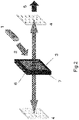
- a schematic diagram of a standard laser application is shown in Fig. 2 .
- a laser medium 3 (Yb:YAG ceramic or the like), which is a phosphor, is excited with excitation light 2 of a laser diode 1, optically amplified in a resonator sandwiched with opposing high reflective mirrors 4, 4', and thereafter emitted as a laser 5.
- an end face of the laser medium 3 becomes the reflecting surface, and parasitic oscillation 6, which laser-oscillates in a direction that differs from the surface formed with the mirrors 4, 4', is generated.
- parasitic oscillation 6 occurs, since the output will be lower than the original laser beam expected from the resonator configured from the opposing mirrors 4, 4', the parasitic oscillation 6 needs to be reduced.
- a light-absorbing layer 7 which has an equivalent refractive index around the laser medium and which absorbs light at an oscillation wavelength range of the laser medium.
- a Cr:YAG ceramic doped with a transition metal such as Cr as the light-absorbing layer 7, the parasitic oscillation 6 can be prevented.
- the Applicant has previously proposed using, as the light-absorbing layer, glass (optical glass) having an absorption coefficient of 0.1 to 10.0cm -1 , a refractive index difference with the laser medium that is within ⁇ 0.1, and a linear thermal expansion coefficient difference with the laser medium is within ⁇ 1 ppm/K ( Japanese Patent Application No. 2019-002307 ).
- the present invention can be applied even when bonding multiple YAG ceramics of the same quality via a glass bonding layer for a purpose other than a bond with the light-absorbing layer; for example, a purpose for increasing the diameter of the YAG ceramic as the laser medium.
- a YAG ceramic As a YAG ceramic, two sheets of 0.5at%Yb:YAG (2 cm ⁇ 1 cm, thickness of 5 mm) were prepared, and a glass material (LX-57B: manufactured by Nippon Electric Glass Co., Ltd.) was prepared as a bonding layer. The glass material was melted at 1000°C, the melted glass was coated on a surface of one YAG ceramic, thereafter bonded to the other YAG ceramic, and a YAG ceramic bonded body was thereby prepared.
- the refractive index of the Yb:YAG ceramic is 1.83 relative to light having a wavelength of 650 nm
- the refractive index of the glass material of the bonding layer is 1.71 relative to the foregoing wavelength.
- the coefficient of thermal expansion of a Yb:YAG ceramic is 8 ppm/K
- the coefficient of thermal expansion of a glass material is 8 ppm/K.
- a laser beam (wavelength: 650 nm) was caused to enter a YAG ceramic base material (before bonding) and the obtained YAG ceramic bonded body (after bonding), respectively, and the transmittance before and after bonding was measured and compared. As a result, the rate of change was 7%, and suppression of light reflection at the bonded interface was confirmed. Moreover, it was confirmed that no separation or cracks occurred even in a high-temperature environment of 600°C, which is the glass transition point of the bonded body, and even in a low-temperature environment such as the liquid nitrogen temperature.
- Example 1 YAG Ceramic / Bonding Glass / YAG Ceramic Refractive Index (wavelength of 650 nm) Coefficient of Thermal Expansion (ppm/K) Rate of Change of Transmittance (Transmittance of Bonded Body / Transmittance of Matrix) Low Temperature Resistance of Bonded Body (Liquid Nitrogen Temperature) High Temperature Resistance of Bonded Body (temperature of 600°C) YAG Ceramic (Matrix) 1.83 8 Bonding Glass 1.71 8 Bonded Body (YAG Ceramic / Bonding Glass / YAG Ceramic) 7% No separation or crack No separation or crack No separation or crack No separation or crack
- a YAG ceramic As a YAG ceramic, 0.5at%Yb:YAG (2 cm ⁇ 1 cm, thickness of 5 mm) and titanosilicate-based glass (optical glass: 2 cm ⁇ 1 cm, thickness of 5 mm) were prepared, and a glass material that is the same as the optical glass was prepared as a bonding layer. The glass material was melted at 1250°C, the melted glass was coated on a surface of a YAG ceramic, thereafter bonded to the optical glass, and a YAG ceramic bonded body was thereby prepared. Note that the refractive index of optical glass is 1.81 relative to light having a wavelength of 650 nm, and the coefficient of thermal expansion is 7 ppm/K.
- a laser beam (wavelength: 650 nm) was caused to enter a YAG ceramic base material (before bonding) and the obtained YAG ceramic bonded body (after bonding), respectively, and the transmittance before and after bonding was compared. As a result, the rate of change was 1.5%, and suppression of light reflection at the bonded interface was confirmed. Moreover, it was confirmed that no separation or cracks occurred even in a high-temperature environment of 700°C, which is the glass transition point of the bonded body, and even in a low-temperature environment such as the liquid nitrogen temperature.
- Example 2 YAG Ceramic / Optical Glass Refractive Index (wavelength of 650 nm) Coefficient of Thermal Expansion (ppm/K) Rate of Change of Transmittance (Transmittance of Bonded Body / Transmittance of Matrix) Low Temperature Resistance of Bonded Body (Liquid Nitrogen Temperature) High Temperature Resistance of Bonded Body (temperature of 700°C) YAG Ceramic (Matrix) 1.83 8 Optical Glass (Titanosilicate Glass) 1.81 9 Bonded Body (YAG Ceramic / Optical Glass) 1.5% No separation or crack No separation or crack No separation or crack
- the present invention is able to yield a superior effect of being able to provide a bonded body of a YAG ceramic and a YAG ceramic or a bonded body of a YAG ceramic and optical glass capable of suppressing light reflection at the bonded interface in which breakage will not occur easily even when there is a temperature change.
- the ceramic bonded body according to the present invention is useful in laser applications such as a high-power laser (amplifier).
Landscapes
- Physics & Mathematics (AREA)
- Electromagnetism (AREA)
- Engineering & Computer Science (AREA)
- Chemical & Material Sciences (AREA)
- Optics & Photonics (AREA)
- Plasma & Fusion (AREA)
- Ceramic Engineering (AREA)
- Crystallography & Structural Chemistry (AREA)
- Organic Chemistry (AREA)
- Structural Engineering (AREA)
- Materials Engineering (AREA)
- Lasers (AREA)
- Ceramic Products (AREA)
- Laser Beam Processing (AREA)
- Joining Of Glass To Other Materials (AREA)
Abstract
Description
- The present invention generally relates to a YAG (yttrium-aluminum-garnet) ceramic bonded body, and particularly relates to a YAG ceramic bonded body in which glass is interposed as a bonding layer as well as to the production method thereof.
- A standard laser is an application which excites a laser medium, which is a phosphor, and optically amplifies the laser medium in a resonator which is sandwiched with optically opposing high reflectance mirrors. As a representative example of a high-power laser medium, YAG ceramics are used. Moreover, other than cases where a laser medium itself becomes the oscillation source, there is also an application as an amplifier which amplifies the laser beam output generated from a separate medium.
- Properties of a YAG ceramic change considerably when doped with a dopant such as Nd, Sm, Yb, or Cr. As an amplifier, the development of light-absorbing layer YAG polycrystals in which the circumference of the Nd:YAG polycrystalline material is doped with Sm has been reported (
Non-Patent Documents 1, 2). Moreover, high-power operation has been confirmed by bonding a Cr-doped polycrystalline body to a Yb:YAG laser polycrystalline body having superior energy storage (Non-Patent Document 3). - The YAG ceramics are exclusively used for a high-power laser, and demanded is a technology for bonding a YAG ceramic of different dopants and light-absorbing optical glass, as a light-absorbing layer for preventing parasitic oscillation, to a YAG ceramic of the laser oscillation part. Moreover, there are also demands for large-diameter transparent YAG ceramics, and required is a technology for bonding a YAG ceramic and a YAG ceramic, or bonding a YAG ceramic and light-absorbing optical glass, for satisfying the foregoing demands.
- [Patent Document 1]
Japanese Unexamined Patent Application Publication (Translation of PCT Application) No. 2014-519721 -
- [Non-Patent Document 1] A. Ikesue, Y. L. Aung, Nature Photonics 22, 721-727 (2008)
- [Non-Patent Document 2] Yamamoto, R.M. et al., Roc, Adv. Solid State Photon, Nara, Japan WC5 (2008)
- [Non-Patent Document 3] S. Banerjee, et al., Opt. Lett. 37, 2175-2177 (2012)
- The present invention was devised in view of the foregoing circumstances, and an object of this invention is to provide a bonded body in which a YAG ceramic and a YAG ceramic are bonded, or a bonded body in which a YAG ceramic and optical glass are bonded, and which is capable of suppressing the reflection of light at the bonded interface, as well as the production method thereof.
- In order to achieve the foregoing object, an embodiment of the present invention is a YAG ceramic bonded body in which a YAG ceramic and a YAG ceramic or optical glass are bonded, wherein the YAG ceramic bonded body comprises glass as a bonding layer and has a rate of change of transmittance that is within 7%.
- According to the present invention, it is possible to yield a superior effect of providing a bonded body of a YAG ceramic and a YAG ceramic, or a bonded body of a YAG ceramic and optical glass, in which the reflection of light at the bonded interface is suppressed.
-
- [
Fig. 1 ]
Fig. 1 is a schematic diagram of the YAG ceramic bonded body according to an embodiment of the present invention. - [
Fig. 2 ]
Fig. 2 is a schematic diagram of the standard laser application. - The bonding of a ceramic and a ceramic has been reported in the past, and this performed by flattening the surfaces to be bonded, applying pressure while applying temperature, and diffusion-bonding the ceramics based on their atomic diffusion. In this diffusion bonding, the surfaces to be bonded are polished into a mirror surface, and the temperature is increased in a state where the surfaces to be bonded are in contact so as to attain a diffusible state. Nevertheless, since the treatment based on diffusion bonding needs to be performed in a furnace of several hundred degrees to one thousand and several hundred degrees, positioning and sophisticated temperature control giving consideration to the thermal expansion of the ceramics are required, and it was difficult to perform bonding with in-plane uniformity. Furthermore, the foregoing treatment becomes even more difficult when the bonded surface area is increased.
- In recent years, as another method of bonding a ceramic and a ceramic, the normal temperature bonding method has been reported. In normal temperature bonding, the object to be bonded is placed in a vacuum chamber, and the contact surface is irradiated with an atom beam or an ion beam such as an Ar beam. On the irradiated surface, the surface bond of the elements will become exposed, and, as a result of causing the surfaces to be bonded to contact each other, a strong bond can thereby be created even at normal temperature without elemental diffusion. Nevertheless, the flatness of the surfaces that can be bonded needs to be increased to an atomic layer level (Ra = order of sub nm to several nm), and while a successful ceramic sample of roughly several cm × cm has been reported, since a size that is any larger will be limited to a high grinding accuracy, there is a problem in that the processing cost becomes high.
- Furthermore, also known is a bonding method using an optical adhesive (Patent Document 1). Nevertheless, an optical adhesive generally has a high coefficient of thermal expansion, and there is a problem in that the strain will increase when the temperature is changed. Moreover, since the main component of the adhesive is an organic material, there is a problem in that the heat resistance (cold resistance) properties are inferior. In particular, when used for laser applications, since it will be under an environment that is exposed to intense light, there is also a problem in that the heat resistance (cold resistance) properties and light resistance properties of organic skeletal components will deteriorate. Furthermore, while nanoparticles are also sometimes included in the adhesive in order to adjust the refractive index, there is concern that the bonding strength may deteriorate depending on the amount of nanoparticles that is included.
- As explained above, it is extremely difficult to bond together ceramics having high transparency and high density (for example, relative density of 99.99% or higher) as represented by laser ceramics, or bond such a ceramic with another optical material. Previously, since optical ceramics (YAG ceramics, etc.) and other optical materials (optical glass, etc.) required transparency, bonding with high bonding strength while maintaining the bonded interface in a favorable state was demanded. With diffusion bonding using the surface diffusion of both materials and with adhesive bonding, it is difficult to prepare a bonded body having transparency and resistance properties, and a fundamental solution for realizing uniform bonding at a mass production level has been desired.
- Thus, the present inventors took particular note of bonding using a glass material. Since glass is a material having considerable formativeness; that is, combined properties of a solid nature having elasticity at room temperature and a liquid nature having fluidity when the temperature is increased, it is a material with a broad range of material formation. The present invention is characterized in using this kind of glass as a bonding layer, and having prepared a bonded body of a YAG ceramic and a YAG ceramic, or a bonded body of a YAG ceramic and another optical material (optical glass). A YAG ceramic bonded body which uses glass as the bonding layer has high transmittance and suppressed light reflection at the bonded interface, and is extremely useful in laser applications.
- The ceramic bonded body according to this embodiment is a YAG ceramic bonded body in which a YAG ceramic and a YAG ceramic or optical glass are bonded, wherein the YAG ceramic bonded body comprises glass as a bonding layer, and has a rate of change of transmittance that is within 7%. Preferably, the rate of change is within 5%, and more preferably the rate of change is within 3%.
- Here, the rate of change of transmittance is calculated based on the following formula by causing light (laser diode) having a wavelength of 650 nm to enter a YAG ceramic base material (before bonding) and the YAG ceramic bonded body (after bonding), and measuring the transmittance thereof.

- When the rate of change of transmittance is within 7%, it could be said that the reflection of light has been sufficiently suppressed at the bonded interface, and the ceramic bonded body can be used in laser applications.
- Moreover, in an embodiment of the present invention, as the glass to be used as a bonding layer, preferably used is a glass material having a refractive index of 1.71 to 1.91 relative to light having a wavelength of 650 nm. While this also depends on the type of dopant, the refractive index of a YAG ceramic, which is the object to be bonded, is roughly 1.83, and, since optical glass used for suppressing parasitic oscillation has a refractive index that is equivalent to that of the YAG ceramic as the laser medium, by using a glass material having an equivalent refractive index (1.71 to 1.91: wavelength of 650 nm), yielded is a superior effect of being able to suppress the reflection of light and attain high transmittance at the bonded interface in the YAG ceramic bonded body.
- Glass as a bonding layer is a transparent material having silicate as its main component, and used may be, for example, an alkalisilicate-based glass material, aluminosilicate-based glass, borosilicate-based glass, germanosilicate-based glass, lead-based glass, and bismuth borate-based glass. Moreover, when giving consideration to the bonding process, while it is preferable to use glass having a low melting point (melting point: 1500°C or less), even if the melting point is high, there will be no problem so as long as the refractive index is a value that is close to that of the YAG ceramic or optical glass. Moreover, it is possible to use a material in which a part or all of the glass material is crystallized.
- A YAG ceramic is a bulk material in which a dopant (Nd, Yb, Cr, Sm, Er or the like) for laser oscillation or light absorption is added to a polycrystalline body having Y3Al5O12 as the matrix. Moreover, there is no absorption by the doped element, and the transmittance from the visible light region (wavelength of 380 nm to 760 nm) to the vicinity of the infrared region (upper limit is wavelength of 3000 nm) is 80% or higher. While the refractive index of a YAG ceramic may slightly change depending on the type of dopant, it is roughly 1.83 relative to light having a wavelength of 650 nm. In order to obtain a high-density body, it is preferable to use a material having few residual pores in the bulk, and an additive-free YAG ceramic may also be used depending on the purpose.
- Optical glass absorbs light oscillated from a YAG ceramic, and can be used as a light-absorbing layer (clad) for reducing parasitic oscillation. Optical glass has a refractive index (refractive index relative to light having a wavelength of 650 nm is 1.71 to 1.91) and a coefficient of thermal expansion (7 to 9 ppm/K) equivalent to that of a YAG ceramic forming a laser medium (core), and preferably used is a material having light absorption at a YAG oscillation wavelength (wavelength of 1030 nm, 1064 nm).
- Next, an example of the production method of a YAG ceramic bonded body according to an embodiment of the present invention and an application example of the YAG ceramic bonded body are explained.
- In order to bond a YAG ceramic and a YAG ceramic or optical glass, melted glass (adhesive glass) is coated on a surface of one YAG ceramic, another YAG ceramic or optical glass is bonded to the coated surface, and, by thereafter performing slow cooling, it is possible to prepare a YAG ceramic bonded body in which glass is interposed as a bonding layer as shown in
Fig. 1 . Moreover, by using a material (such as titanosilicate glass) having the same quality as optical glass as the adhesive glass, it is possible to prepare a bonded body substantially composed of YAG ceramic/optical glass. - A YAG ceramic bonded body that is bonded via glass as a bonding layer can be used, for example, in the following laser applications.
- A schematic diagram of a standard laser application is shown in
Fig. 2 . A laser medium 3 (Yb:YAG ceramic or the like), which is a phosphor, is excited withexcitation light 2 of alaser diode 1, optically amplified in a resonator sandwiched with opposing highreflective mirrors 4, 4', and thereafter emitted as alaser 5. Here, an end face of thelaser medium 3 becomes the reflecting surface, and parasitic oscillation 6, which laser-oscillates in a direction that differs from the surface formed with themirrors 4, 4', is generated. When this parasitic oscillation 6 occurs, since the output will be lower than the original laser beam expected from the resonator configured from the opposingmirrors 4, 4', the parasitic oscillation 6 needs to be reduced. - In order to reduce this parasitic oscillation 6, formed is a light-absorbing
layer 7 which has an equivalent refractive index around the laser medium and which absorbs light at an oscillation wavelength range of the laser medium. By bonding a Cr:YAG ceramic doped with a transition metal such as Cr as the light-absorbinglayer 7, the parasitic oscillation 6 can be prevented. Moreover, the Applicant has previously proposed using, as the light-absorbing layer, glass (optical glass) having an absorption coefficient of 0.1 to 10.0cm-1, a refractive index difference with the laser medium that is within ±0.1, and a linear thermal expansion coefficient difference with the laser medium is within ±1 ppm/K (Japanese Patent Application No. 2019-002307 - In the bond of a Yb:YAG ceramic as the laser medium and a Cr:YAG ceramic or optical glass as the light-absorbing layer, it is possible to apply the bonded body of a YAG ceramic and a YAG ceramic or a bonded body of a YAG ceramic and another optical material (optical glass) using the glass according to the present invention as the bonding layer. Note that, while a bond of a YAG ceramic as the laser medium and a YAG ceramic or optical glass as the light-absorbing layer was explained above, the present invention can be applied even when bonding multiple YAG ceramics of the same quality via a glass bonding layer for a purpose other than a bond with the light-absorbing layer; for example, a purpose for increasing the diameter of the YAG ceramic as the laser medium.
- The present invention is now explained with reference to the Examples and Comparative Examples. Note that these Examples are merely illustrative, and the present invention shall in no way be limited thereby. In other words, various modifications and other embodiments are covered by the present invention, and the present invention is limited only by the scope of its claims.
- As a YAG ceramic, two sheets of 0.5at%Yb:YAG (2 cm × 1 cm, thickness of 5 mm) were prepared, and a glass material (LX-57B: manufactured by Nippon Electric Glass Co., Ltd.) was prepared as a bonding layer. The glass material was melted at 1000°C, the melted glass was coated on a surface of one YAG ceramic, thereafter bonded to the other YAG ceramic, and a YAG ceramic bonded body was thereby prepared. Note that the refractive index of the Yb:YAG ceramic is 1.83 relative to light having a wavelength of 650 nm, and the refractive index of the glass material of the bonding layer is 1.71 relative to the foregoing wavelength. Moreover, the coefficient of thermal expansion of a Yb:YAG ceramic is 8 ppm/K, and the coefficient of thermal expansion of a glass material is 8 ppm/K.
- A laser beam (wavelength: 650 nm) was caused to enter a YAG ceramic base material (before bonding) and the obtained YAG ceramic bonded body (after bonding), respectively, and the transmittance before and after bonding was measured and compared. As a result, the rate of change was 7%, and suppression of light reflection at the bonded interface was confirmed. Moreover, it was confirmed that no separation or cracks occurred even in a high-temperature environment of 600°C, which is the glass transition point of the bonded body, and even in a low-temperature environment such as the liquid nitrogen temperature.
[Table 1] (Example 1) YAG Ceramic / Bonding Glass / YAG Ceramic Refractive Index (wavelength of 650 nm) Coefficient of Thermal Expansion (ppm/K) Rate of Change of Transmittance (Transmittance of Bonded Body / Transmittance of Matrix) Low Temperature Resistance of Bonded Body (Liquid Nitrogen Temperature) High Temperature Resistance of Bonded Body (temperature of 600°C) YAG Ceramic (Matrix) 1.83 8 Bonding Glass 1.71 8 Bonded Body (YAG Ceramic / Bonding Glass / YAG Ceramic) 7% No separation or crack No separation or crack - As a YAG ceramic, 0.5at%Yb:YAG (2 cm × 1 cm, thickness of 5 mm) and titanosilicate-based glass (optical glass: 2 cm × 1 cm, thickness of 5 mm) were prepared, and a glass material that is the same as the optical glass was prepared as a bonding layer. The glass material was melted at 1250°C, the melted glass was coated on a surface of a YAG ceramic, thereafter bonded to the optical glass, and a YAG ceramic bonded body was thereby prepared. Note that the refractive index of optical glass is 1.81 relative to light having a wavelength of 650 nm, and the coefficient of thermal expansion is 7 ppm/K.
- A laser beam (wavelength: 650 nm) was caused to enter a YAG ceramic base material (before bonding) and the obtained YAG ceramic bonded body (after bonding), respectively, and the transmittance before and after bonding was compared. As a result, the rate of change was 1.5%, and suppression of light reflection at the bonded interface was confirmed. Moreover, it was confirmed that no separation or cracks occurred even in a high-temperature environment of 700°C, which is the glass transition point of the bonded body, and even in a low-temperature environment such as the liquid nitrogen temperature.
[Table 2] (Example 2) YAG Ceramic / Optical Glass Refractive Index (wavelength of 650 nm) Coefficient of Thermal Expansion (ppm/K) Rate of Change of Transmittance (Transmittance of Bonded Body / Transmittance of Matrix) Low Temperature Resistance of Bonded Body (Liquid Nitrogen Temperature) High Temperature Resistance of Bonded Body (temperature of 700°C) YAG Ceramic (Matrix) 1.83 8 Optical Glass (Titanosilicate Glass) 1.81 9 Bonded Body (YAG Ceramic / Optical Glass) 1.5% No separation or crack No separation or crack - The present invention is able to yield a superior effect of being able to provide a bonded body of a YAG ceramic and a YAG ceramic or a bonded body of a YAG ceramic and optical glass capable of suppressing light reflection at the bonded interface in which breakage will not occur easily even when there is a temperature change. The ceramic bonded body according to the present invention is useful in laser applications such as a high-power laser (amplifier).
-
- 1
- laser diode
- 2
- excitation light
- 3
- laser medium (core)
- 4
- mirrors
- 5
- laser
- 6
- parasitic oscillation
- 7
- light-absorbing layer (clad)
Claims (5)
- A YAG ceramic bonded body in which a YAG ceramic and a YAG ceramic or optical glass are bonded, wherein the YAG ceramic bonded body comprises glass as a bonding layer, and has a rate of change of transmittance that is within 7%.
- The YAG ceramic bonded body according to claim 1,
wherein the glass as the bonding layer has a refractive index of 1.71 to 1.91 relative to light having a wavelength of 650 nm. - The YAG ceramic bonded body according to claim 1 or claim 2,
wherein the YAG ceramic bonded body in which a YAG ceramic and a YAG ceramic are bonded is obtained by bonding Yb:YAG and Yb:YAG, Nd:YAG and Nd:YAG, Yb:YAG and Cr:YAG, or Yb:YAG and Sm:YAG. - The YAG ceramic bonded body according to claim 1 or claim 2,
wherein the optical glass has a refractive index of 1.71 to 1.91 relative to light having a wavelength of 650 nm, and has a coefficient of thermal expansion of 7 to 9 ppm/K. - A method of producing the YAG ceramic bonded body according to any one of claims 1 to 4, wherein melted glass is coated on a surface of one YAG ceramic, another YAG ceramic or optical glass is bonded to the surface coated with the glass, and thereafter cooled.
Applications Claiming Priority (2)
| Application Number | Priority Date | Filing Date | Title |
|---|---|---|---|
| JP2020019898 | 2020-02-07 | ||
| PCT/JP2020/038554 WO2021157135A1 (en) | 2020-02-07 | 2020-10-13 | Yag ceramic joined body and production method therefor |
Publications (2)
| Publication Number | Publication Date |
|---|---|
| EP4023621A1 true EP4023621A1 (en) | 2022-07-06 |
| EP4023621A4 EP4023621A4 (en) | 2023-11-08 |
Family
ID=77199873
Family Applications (1)
| Application Number | Title | Priority Date | Filing Date |
|---|---|---|---|
| EP20917282.4A Pending EP4023621A4 (en) | 2020-02-07 | 2020-10-13 | Yag ceramic joined body and production method therefor |
Country Status (5)
| Country | Link |
|---|---|
| US (1) | US12160081B2 (en) |
| EP (1) | EP4023621A4 (en) |
| JP (2) | JP7503579B2 (en) |
| CN (1) | CN114502520B (en) |
| WO (1) | WO2021157135A1 (en) |
Family Cites Families (27)
| Publication number | Priority date | Publication date | Assignee | Title |
|---|---|---|---|---|
| US4509175A (en) | 1982-09-14 | 1985-04-02 | Quantronix Corporation | Segmented YAG laser rods and method of manufacture |
| US4507787A (en) * | 1982-09-28 | 1985-03-26 | Quantronix Corporation | Segmented YAG laser rods and methods of manufacture |
| JPS62226838A (en) | 1986-03-28 | 1987-10-05 | Hoya Corp | Cladding glass for gd-sc-ga-garnet single crystal and its cladding method |
| US5441803A (en) * | 1988-08-30 | 1995-08-15 | Onyx Optics | Composites made from single crystal substances |
| US5846638A (en) * | 1988-08-30 | 1998-12-08 | Onyx Optics, Inc. | Composite optical and electro-optical devices |
| JPH0597530A (en) * | 1991-10-04 | 1993-04-20 | Kobe Steel Ltd | Bonding of sintered ceramics |
| US6650670B1 (en) * | 2000-07-13 | 2003-11-18 | Yutaka Shimoji | Polycrystalline ceramic laser |
| US6587488B1 (en) * | 2000-11-08 | 2003-07-01 | Maxios Laser Corporation | Control of parasitic laser oscillations in solid-state lasers by frustrating total internal reflections |
| US7200161B2 (en) * | 2001-01-22 | 2007-04-03 | The Boeing Company | Side-pumped solid-state disk laser for high-average power |
| US6810060B2 (en) * | 2001-02-13 | 2004-10-26 | The Boeing Company | High-average power active mirror solid-state laser with multiple subapertures |
| TW567177B (en) * | 2001-07-19 | 2003-12-21 | Ibiden Co Ltd | Ceramic connection body, method of connecting the ceramic bodies, and ceramic structural body |
| TW200301980A (en) * | 2002-01-10 | 2003-07-16 | Hrl Lab Llc | Diffusion bonded pump cavity |
| JP2003313083A (en) * | 2002-04-22 | 2003-11-06 | Toshiba Ceramics Co Ltd | Bonded body of yttrium compound and bonding method thereof |
| US7085304B2 (en) | 2003-05-19 | 2006-08-01 | The Boeing Company | Diode-pumped solid state disk laser and method for producing uniform laser gain |
| JPWO2005091447A1 (en) * | 2004-03-24 | 2008-02-07 | 独立行政法人科学技術振興機構 | Laser equipment |
| US7463660B2 (en) * | 2004-05-11 | 2008-12-09 | Lawrence Livermore National Laboratory, Llc | Gain media edge treatment to suppress amplified spontaneous emission in a high power laser |
| US7361938B2 (en) * | 2004-06-03 | 2008-04-22 | Philips Lumileds Lighting Company Llc | Luminescent ceramic for a light emitting device |
| US7630423B2 (en) * | 2005-04-12 | 2009-12-08 | Raytheon Company | Glaze soldered laser components and method of manufacturing |
| JP2011146556A (en) * | 2010-01-15 | 2011-07-28 | National Institutes Of Natural Sciences | Semiconductor laser excitation solid-state laser device |
| RU2013148791A (en) * | 2011-06-13 | 2015-07-20 | ЛОРЕНС ЛИВЕРМОР НЭШНЛ СЕКЬЮРИТИ, ЭлЭлСи | METHOD AND SYSTEM FOR CRYOGENICALLY COOLED LASER AMPLIFIER |
| US8774235B2 (en) * | 2011-06-23 | 2014-07-08 | Raytheon Company | System and method for suppressing parasitics in an optical device |
| JP5734511B2 (en) * | 2012-05-09 | 2015-06-17 | 三菱電機株式会社 | Passive Q switch element |
| DE102016118364B3 (en) * | 2016-09-28 | 2018-03-08 | Schott Ag | Cladding glass for solid-state lasers |
| JP2019002307A (en) | 2017-06-14 | 2019-01-10 | 日立オートモティブシステムズ株式会社 | Vehicle control device |
| CN110709368B (en) | 2018-03-30 | 2022-07-26 | 捷客斯金属株式会社 | Polycrystalline YAG sintered body and method for producing same |
| CN112654588A (en) * | 2019-01-10 | 2021-04-13 | 捷客斯金属株式会社 | Light-absorbing layer and bonded body having light-absorbing layer |
| WO2020166139A1 (en) | 2019-02-12 | 2020-08-20 | Jx金属株式会社 | Cr:yag sintered body |
-
2020
- 2020-10-13 WO PCT/JP2020/038554 patent/WO2021157135A1/en not_active Ceased
- 2020-10-13 US US17/763,451 patent/US12160081B2/en active Active
- 2020-10-13 EP EP20917282.4A patent/EP4023621A4/en active Pending
- 2020-10-13 JP JP2021575609A patent/JP7503579B2/en active Active
- 2020-10-13 CN CN202080069254.2A patent/CN114502520B/en active Active
-
2022
- 2022-12-23 JP JP2022206720A patent/JP2023029447A/en not_active Withdrawn
Also Published As
| Publication number | Publication date |
|---|---|
| CN114502520B (en) | 2023-12-05 |
| JP2023029447A (en) | 2023-03-03 |
| US12160081B2 (en) | 2024-12-03 |
| CN114502520A (en) | 2022-05-13 |
| US20220393424A1 (en) | 2022-12-08 |
| JPWO2021157135A1 (en) | 2021-08-12 |
| JP7503579B2 (en) | 2024-06-20 |
| EP4023621A4 (en) | 2023-11-08 |
| WO2021157135A1 (en) | 2021-08-12 |
Similar Documents
| Publication | Publication Date | Title |
|---|---|---|
| US5852622A (en) | Solid state lasers with composite crystal or glass components | |
| US5563899A (en) | Composite solid state lasers of improved efficiency and beam quality | |
| US5846638A (en) | Composite optical and electro-optical devices | |
| US5936984A (en) | Laser rods with undoped, flanged end-caps for end-pumped laser applications | |
| EP2361231B1 (en) | Optical components for use in high energy environment with improved optical characteristics | |
| US20070062921A1 (en) | Full-body laser scribing method of fragile material | |
| US10054735B2 (en) | Method and apparatus for producing crystalline cladding and crystalline core optical fibers | |
| CN107867800B (en) | Cladding glass for solid state lasers | |
| Wentsch et al. | Yb: CaF2 thin-disk laser | |
| US4509175A (en) | Segmented YAG laser rods and method of manufacture | |
| EP1834387B1 (en) | Glaze cladding for laser components | |
| Wan et al. | Exceeding 50% slope efficiency DBR fiber laser based on a Yb-doped crystal-derived silica fiber with high gain per unit length | |
| US8682125B2 (en) | Method and system for edge cladding of laser gain media | |
| US12160081B2 (en) | YAG ceramic joined body and production method therefor | |
| EP2354103B1 (en) | Light-amplifying glass | |
| JP7052088B2 (en) | Bonded body with light-absorbing layer and light-absorbing layer | |
| EP1713149B1 (en) | Glaze soldered laser components and method of manufacturing | |
| CN112250299B (en) | Cladding glass for solid-state lasers | |
| EP0832858A2 (en) | Sealing glass, and a method for manufacturing the same | |
| US7087447B2 (en) | Method for fabricating zig-zag slabs for solid state lasers | |
| CN121675082A (en) | Preparation method of gradient doped single crystal optical fiber with two ends being compounded | |
| CN118344171A (en) | An indirect bonding method of erbium glass and cobalt spinel | |
| JP2023175081A (en) | Crystalline solid-state laser medium composite and its manufacturing method | |
| Vretenar | Room temperature and cryogenic Yb: YAG thin disk laser: single crystal and ceramic | |
| Sridharan et al. | Method for fabricating zig-zag slabs for solid state lasers |
Legal Events
| Date | Code | Title | Description |
|---|---|---|---|
| STAA | Information on the status of an ep patent application or granted ep patent |
Free format text: STATUS: THE INTERNATIONAL PUBLICATION HAS BEEN MADE |
|
| PUAI | Public reference made under article 153(3) epc to a published international application that has entered the european phase |
Free format text: ORIGINAL CODE: 0009012 |
|
| STAA | Information on the status of an ep patent application or granted ep patent |
Free format text: STATUS: REQUEST FOR EXAMINATION WAS MADE |
|
| 17P | Request for examination filed |
Effective date: 20220331 |
|
| AK | Designated contracting states |
Kind code of ref document: A1 Designated state(s): AL AT BE BG CH CY CZ DE DK EE ES FI FR GB GR HR HU IE IS IT LI LT LU LV MC MK MT NL NO PL PT RO RS SE SI SK SM TR |
|
| DAV | Request for validation of the european patent (deleted) | ||
| DAX | Request for extension of the european patent (deleted) | ||
| A4 | Supplementary search report drawn up and despatched |
Effective date: 20231006 |
|
| RIC1 | Information provided on ipc code assigned before grant |
Ipc: H01S 3/06 20060101ALI20230929BHEP Ipc: C04B 35/505 20060101ALI20230929BHEP Ipc: C04B 37/00 20060101AFI20230929BHEP |