EP4023434A1 - Curved panel member - Google Patents
Curved panel member Download PDFInfo
- Publication number
- EP4023434A1 EP4023434A1 EP19947752.2A EP19947752A EP4023434A1 EP 4023434 A1 EP4023434 A1 EP 4023434A1 EP 19947752 A EP19947752 A EP 19947752A EP 4023434 A1 EP4023434 A1 EP 4023434A1
- Authority
- EP
- European Patent Office
- Prior art keywords
- curved panel
- frp
- layers
- reinforcement
- curved
- Prior art date
- Legal status (The legal status is an assumption and is not a legal conclusion. Google has not performed a legal analysis and makes no representation as to the accuracy of the status listed.)
- Pending
Links
Images



Classifications
-
- B—PERFORMING OPERATIONS; TRANSPORTING
- B32—LAYERED PRODUCTS
- B32B—LAYERED PRODUCTS, i.e. PRODUCTS BUILT-UP OF STRATA OF FLAT OR NON-FLAT, e.g. CELLULAR OR HONEYCOMB, FORM
- B32B7/00—Layered products characterised by the relation between layers; Layered products characterised by the relative orientation of features between layers, or by the relative values of a measurable parameter between layers, i.e. products comprising layers having different physical, chemical or physicochemical properties; Layered products characterised by the interconnection of layers
- B32B7/03—Layered products characterised by the relation between layers; Layered products characterised by the relative orientation of features between layers, or by the relative values of a measurable parameter between layers, i.e. products comprising layers having different physical, chemical or physicochemical properties; Layered products characterised by the interconnection of layers with respect to the orientation of features
-
- B—PERFORMING OPERATIONS; TRANSPORTING
- B60—VEHICLES IN GENERAL
- B60J—WINDOWS, WINDSCREENS, NON-FIXED ROOFS, DOORS, OR SIMILAR DEVICES FOR VEHICLES; REMOVABLE EXTERNAL PROTECTIVE COVERINGS SPECIALLY ADAPTED FOR VEHICLES
- B60J5/00—Doors
- B60J5/04—Doors arranged at the vehicle sides
- B60J5/048—Doors arranged at the vehicle sides characterised by the material
- B60J5/0484—Doors arranged at the vehicle sides characterised by the material hybrid, i.e. plastic moulded onto metal parts
-
- B—PERFORMING OPERATIONS; TRANSPORTING
- B29—WORKING OF PLASTICS; WORKING OF SUBSTANCES IN A PLASTIC STATE IN GENERAL
- B29C—SHAPING OR JOINING OF PLASTICS; SHAPING OF MATERIAL IN A PLASTIC STATE, NOT OTHERWISE PROVIDED FOR; AFTER-TREATMENT OF THE SHAPED PRODUCTS, e.g. REPAIRING
- B29C70/00—Shaping composites, i.e. plastics material comprising reinforcements, fillers or preformed parts, e.g. inserts
- B29C70/04—Shaping composites, i.e. plastics material comprising reinforcements, fillers or preformed parts, e.g. inserts comprising reinforcements only, e.g. self-reinforcing plastics
- B29C70/06—Fibrous reinforcements only
- B29C70/10—Fibrous reinforcements only characterised by the structure of fibrous reinforcements, e.g. hollow fibres
- B29C70/16—Fibrous reinforcements only characterised by the structure of fibrous reinforcements, e.g. hollow fibres using fibres of substantial or continuous length
- B29C70/20—Fibrous reinforcements only characterised by the structure of fibrous reinforcements, e.g. hollow fibres using fibres of substantial or continuous length oriented in a single direction, e.g. roofing or other parallel fibres
- B29C70/205—Fibrous reinforcements only characterised by the structure of fibrous reinforcements, e.g. hollow fibres using fibres of substantial or continuous length oriented in a single direction, e.g. roofing or other parallel fibres the structure being shaped to form a three-dimensional configuration
- B29C70/207—Fibrous reinforcements only characterised by the structure of fibrous reinforcements, e.g. hollow fibres using fibres of substantial or continuous length oriented in a single direction, e.g. roofing or other parallel fibres the structure being shaped to form a three-dimensional configuration arranged in parallel planes of fibres crossing at substantial angles
-
- B—PERFORMING OPERATIONS; TRANSPORTING
- B29—WORKING OF PLASTICS; WORKING OF SUBSTANCES IN A PLASTIC STATE IN GENERAL
- B29C—SHAPING OR JOINING OF PLASTICS; SHAPING OF MATERIAL IN A PLASTIC STATE, NOT OTHERWISE PROVIDED FOR; AFTER-TREATMENT OF THE SHAPED PRODUCTS, e.g. REPAIRING
- B29C70/00—Shaping composites, i.e. plastics material comprising reinforcements, fillers or preformed parts, e.g. inserts
- B29C70/88—Shaping composites, i.e. plastics material comprising reinforcements, fillers or preformed parts, e.g. inserts characterised primarily by possessing specific properties, e.g. electrically conductive or locally reinforced
- B29C70/882—Shaping composites, i.e. plastics material comprising reinforcements, fillers or preformed parts, e.g. inserts characterised primarily by possessing specific properties, e.g. electrically conductive or locally reinforced partly or totally electrically conductive, e.g. for EMI shielding
- B29C70/885—Shaping composites, i.e. plastics material comprising reinforcements, fillers or preformed parts, e.g. inserts characterised primarily by possessing specific properties, e.g. electrically conductive or locally reinforced partly or totally electrically conductive, e.g. for EMI shielding with incorporated metallic wires, nets, films or plates
-
- B—PERFORMING OPERATIONS; TRANSPORTING
- B32—LAYERED PRODUCTS
- B32B—LAYERED PRODUCTS, i.e. PRODUCTS BUILT-UP OF STRATA OF FLAT OR NON-FLAT, e.g. CELLULAR OR HONEYCOMB, FORM
- B32B1/00—Layered products having a non-planar shape
-
- B—PERFORMING OPERATIONS; TRANSPORTING
- B32—LAYERED PRODUCTS
- B32B—LAYERED PRODUCTS, i.e. PRODUCTS BUILT-UP OF STRATA OF FLAT OR NON-FLAT, e.g. CELLULAR OR HONEYCOMB, FORM
- B32B15/00—Layered products comprising a layer of metal
- B32B15/04—Layered products comprising a layer of metal comprising metal as the main or only constituent of a layer, which is next to another layer of the same or of a different material
- B32B15/08—Layered products comprising a layer of metal comprising metal as the main or only constituent of a layer, which is next to another layer of the same or of a different material of synthetic resin
-
- B—PERFORMING OPERATIONS; TRANSPORTING
- B32—LAYERED PRODUCTS
- B32B—LAYERED PRODUCTS, i.e. PRODUCTS BUILT-UP OF STRATA OF FLAT OR NON-FLAT, e.g. CELLULAR OR HONEYCOMB, FORM
- B32B15/00—Layered products comprising a layer of metal
- B32B15/14—Layered products comprising a layer of metal next to a fibrous or filamentary layer
-
- B—PERFORMING OPERATIONS; TRANSPORTING
- B32—LAYERED PRODUCTS
- B32B—LAYERED PRODUCTS, i.e. PRODUCTS BUILT-UP OF STRATA OF FLAT OR NON-FLAT, e.g. CELLULAR OR HONEYCOMB, FORM
- B32B15/00—Layered products comprising a layer of metal
- B32B15/18—Layered products comprising a layer of metal comprising iron or steel
-
- B—PERFORMING OPERATIONS; TRANSPORTING
- B32—LAYERED PRODUCTS
- B32B—LAYERED PRODUCTS, i.e. PRODUCTS BUILT-UP OF STRATA OF FLAT OR NON-FLAT, e.g. CELLULAR OR HONEYCOMB, FORM
- B32B27/00—Layered products comprising a layer of synthetic resin
- B32B27/06—Layered products comprising a layer of synthetic resin as the main or only constituent of a layer, which is next to another layer of the same or of a different material
- B32B27/08—Layered products comprising a layer of synthetic resin as the main or only constituent of a layer, which is next to another layer of the same or of a different material of synthetic resin
-
- B—PERFORMING OPERATIONS; TRANSPORTING
- B32—LAYERED PRODUCTS
- B32B—LAYERED PRODUCTS, i.e. PRODUCTS BUILT-UP OF STRATA OF FLAT OR NON-FLAT, e.g. CELLULAR OR HONEYCOMB, FORM
- B32B27/00—Layered products comprising a layer of synthetic resin
- B32B27/18—Layered products comprising a layer of synthetic resin characterised by the use of special additives
- B32B27/20—Layered products comprising a layer of synthetic resin characterised by the use of special additives using fillers, pigments, thixotroping agents
-
- B—PERFORMING OPERATIONS; TRANSPORTING
- B32—LAYERED PRODUCTS
- B32B—LAYERED PRODUCTS, i.e. PRODUCTS BUILT-UP OF STRATA OF FLAT OR NON-FLAT, e.g. CELLULAR OR HONEYCOMB, FORM
- B32B27/00—Layered products comprising a layer of synthetic resin
- B32B27/28—Layered products comprising a layer of synthetic resin comprising synthetic resins not wholly covered by any one of the sub-groups B32B27/30 - B32B27/42
- B32B27/285—Layered products comprising a layer of synthetic resin comprising synthetic resins not wholly covered by any one of the sub-groups B32B27/30 - B32B27/42 comprising polyethers
-
- B—PERFORMING OPERATIONS; TRANSPORTING
- B32—LAYERED PRODUCTS
- B32B—LAYERED PRODUCTS, i.e. PRODUCTS BUILT-UP OF STRATA OF FLAT OR NON-FLAT, e.g. CELLULAR OR HONEYCOMB, FORM
- B32B5/00—Layered products characterised by the non- homogeneity or physical structure, i.e. comprising a fibrous, filamentary, particulate or foam layer; Layered products characterised by having a layer differing constitutionally or physically in different parts
- B32B5/02—Layered products characterised by the non- homogeneity or physical structure, i.e. comprising a fibrous, filamentary, particulate or foam layer; Layered products characterised by having a layer differing constitutionally or physically in different parts characterised by structural features of a fibrous or filamentary layer
- B32B5/12—Layered products characterised by the non- homogeneity or physical structure, i.e. comprising a fibrous, filamentary, particulate or foam layer; Layered products characterised by having a layer differing constitutionally or physically in different parts characterised by structural features of a fibrous or filamentary layer characterised by the relative arrangement of fibres or filaments of different layers, e.g. the fibres or filaments being parallel or perpendicular to each other
-
- B—PERFORMING OPERATIONS; TRANSPORTING
- B32—LAYERED PRODUCTS
- B32B—LAYERED PRODUCTS, i.e. PRODUCTS BUILT-UP OF STRATA OF FLAT OR NON-FLAT, e.g. CELLULAR OR HONEYCOMB, FORM
- B32B5/00—Layered products characterised by the non- homogeneity or physical structure, i.e. comprising a fibrous, filamentary, particulate or foam layer; Layered products characterised by having a layer differing constitutionally or physically in different parts
- B32B5/22—Layered products characterised by the non- homogeneity or physical structure, i.e. comprising a fibrous, filamentary, particulate or foam layer; Layered products characterised by having a layer differing constitutionally or physically in different parts characterised by the presence of two or more layers which are next to each other and are fibrous, filamentary, formed of particles or foamed
- B32B5/24—Layered products characterised by the non- homogeneity or physical structure, i.e. comprising a fibrous, filamentary, particulate or foam layer; Layered products characterised by having a layer differing constitutionally or physically in different parts characterised by the presence of two or more layers which are next to each other and are fibrous, filamentary, formed of particles or foamed one layer being a fibrous or filamentary layer
- B32B5/26—Layered products characterised by the non- homogeneity or physical structure, i.e. comprising a fibrous, filamentary, particulate or foam layer; Layered products characterised by having a layer differing constitutionally or physically in different parts characterised by the presence of two or more layers which are next to each other and are fibrous, filamentary, formed of particles or foamed one layer being a fibrous or filamentary layer another layer next to it also being fibrous or filamentary
-
- B—PERFORMING OPERATIONS; TRANSPORTING
- B32—LAYERED PRODUCTS
- B32B—LAYERED PRODUCTS, i.e. PRODUCTS BUILT-UP OF STRATA OF FLAT OR NON-FLAT, e.g. CELLULAR OR HONEYCOMB, FORM
- B32B7/00—Layered products characterised by the relation between layers; Layered products characterised by the relative orientation of features between layers, or by the relative values of a measurable parameter between layers, i.e. products comprising layers having different physical, chemical or physicochemical properties; Layered products characterised by the interconnection of layers
- B32B7/02—Physical, chemical or physicochemical properties
- B32B7/022—Mechanical properties
-
- B—PERFORMING OPERATIONS; TRANSPORTING
- B32—LAYERED PRODUCTS
- B32B—LAYERED PRODUCTS, i.e. PRODUCTS BUILT-UP OF STRATA OF FLAT OR NON-FLAT, e.g. CELLULAR OR HONEYCOMB, FORM
- B32B7/00—Layered products characterised by the relation between layers; Layered products characterised by the relative orientation of features between layers, or by the relative values of a measurable parameter between layers, i.e. products comprising layers having different physical, chemical or physicochemical properties; Layered products characterised by the interconnection of layers
- B32B7/04—Interconnection of layers
- B32B7/05—Interconnection of layers the layers not being connected over the whole surface, e.g. discontinuous connection or patterned connection
-
- B—PERFORMING OPERATIONS; TRANSPORTING
- B32—LAYERED PRODUCTS
- B32B—LAYERED PRODUCTS, i.e. PRODUCTS BUILT-UP OF STRATA OF FLAT OR NON-FLAT, e.g. CELLULAR OR HONEYCOMB, FORM
- B32B7/00—Layered products characterised by the relation between layers; Layered products characterised by the relative orientation of features between layers, or by the relative values of a measurable parameter between layers, i.e. products comprising layers having different physical, chemical or physicochemical properties; Layered products characterised by the interconnection of layers
- B32B7/04—Interconnection of layers
- B32B7/08—Interconnection of layers by mechanical means
-
- B—PERFORMING OPERATIONS; TRANSPORTING
- B32—LAYERED PRODUCTS
- B32B—LAYERED PRODUCTS, i.e. PRODUCTS BUILT-UP OF STRATA OF FLAT OR NON-FLAT, e.g. CELLULAR OR HONEYCOMB, FORM
- B32B7/00—Layered products characterised by the relation between layers; Layered products characterised by the relative orientation of features between layers, or by the relative values of a measurable parameter between layers, i.e. products comprising layers having different physical, chemical or physicochemical properties; Layered products characterised by the interconnection of layers
- B32B7/04—Interconnection of layers
- B32B7/12—Interconnection of layers using interposed adhesives or interposed materials with bonding properties
-
- B—PERFORMING OPERATIONS; TRANSPORTING
- B62—LAND VEHICLES FOR TRAVELLING OTHERWISE THAN ON RAILS
- B62D—MOTOR VEHICLES; TRAILERS
- B62D25/00—Superstructure or monocoque structure sub-units; Parts or details thereof not otherwise provided for
- B62D25/02—Side panels
-
- B—PERFORMING OPERATIONS; TRANSPORTING
- B62—LAND VEHICLES FOR TRAVELLING OTHERWISE THAN ON RAILS
- B62D—MOTOR VEHICLES; TRAILERS
- B62D25/00—Superstructure or monocoque structure sub-units; Parts or details thereof not otherwise provided for
- B62D25/06—Fixed roofs
-
- B—PERFORMING OPERATIONS; TRANSPORTING
- B62—LAND VEHICLES FOR TRAVELLING OTHERWISE THAN ON RAILS
- B62D—MOTOR VEHICLES; TRAILERS
- B62D25/00—Superstructure or monocoque structure sub-units; Parts or details thereof not otherwise provided for
- B62D25/08—Front or rear portions
- B62D25/10—Bonnets or lids, e.g. for trucks, tractors, busses, work vehicles
-
- B—PERFORMING OPERATIONS; TRANSPORTING
- B62—LAND VEHICLES FOR TRAVELLING OTHERWISE THAN ON RAILS
- B62D—MOTOR VEHICLES; TRAILERS
- B62D25/00—Superstructure or monocoque structure sub-units; Parts or details thereof not otherwise provided for
- B62D25/08—Front or rear portions
- B62D25/16—Mud-guards or wings; Wheel cover panels
-
- B—PERFORMING OPERATIONS; TRANSPORTING
- B62—LAND VEHICLES FOR TRAVELLING OTHERWISE THAN ON RAILS
- B62D—MOTOR VEHICLES; TRAILERS
- B62D29/00—Superstructures, understructures, or sub-units thereof, characterised by the material thereof
- B62D29/001—Superstructures, understructures, or sub-units thereof, characterised by the material thereof characterised by combining metal and synthetic material
- B62D29/005—Superstructures, understructures, or sub-units thereof, characterised by the material thereof characterised by combining metal and synthetic material preformed metal and synthetic material elements being joined together, e.g. by adhesives
-
- B—PERFORMING OPERATIONS; TRANSPORTING
- B32—LAYERED PRODUCTS
- B32B—LAYERED PRODUCTS, i.e. PRODUCTS BUILT-UP OF STRATA OF FLAT OR NON-FLAT, e.g. CELLULAR OR HONEYCOMB, FORM
- B32B2260/00—Layered product comprising an impregnated, embedded, or bonded layer wherein the layer comprises an impregnation, embedding, or binder material
- B32B2260/02—Composition of the impregnated, bonded or embedded layer
- B32B2260/021—Fibrous or filamentary layer
-
- B—PERFORMING OPERATIONS; TRANSPORTING
- B32—LAYERED PRODUCTS
- B32B—LAYERED PRODUCTS, i.e. PRODUCTS BUILT-UP OF STRATA OF FLAT OR NON-FLAT, e.g. CELLULAR OR HONEYCOMB, FORM
- B32B2260/00—Layered product comprising an impregnated, embedded, or bonded layer wherein the layer comprises an impregnation, embedding, or binder material
- B32B2260/02—Composition of the impregnated, bonded or embedded layer
- B32B2260/021—Fibrous or filamentary layer
- B32B2260/023—Two or more layers
-
- B—PERFORMING OPERATIONS; TRANSPORTING
- B32—LAYERED PRODUCTS
- B32B—LAYERED PRODUCTS, i.e. PRODUCTS BUILT-UP OF STRATA OF FLAT OR NON-FLAT, e.g. CELLULAR OR HONEYCOMB, FORM
- B32B2260/00—Layered product comprising an impregnated, embedded, or bonded layer wherein the layer comprises an impregnation, embedding, or binder material
- B32B2260/04—Impregnation, embedding, or binder material
- B32B2260/046—Synthetic resin
-
- B—PERFORMING OPERATIONS; TRANSPORTING
- B32—LAYERED PRODUCTS
- B32B—LAYERED PRODUCTS, i.e. PRODUCTS BUILT-UP OF STRATA OF FLAT OR NON-FLAT, e.g. CELLULAR OR HONEYCOMB, FORM
- B32B2262/00—Composition or structural features of fibres which form a fibrous or filamentary layer or are present as additives
- B32B2262/10—Inorganic fibres
- B32B2262/101—Glass fibres
-
- B—PERFORMING OPERATIONS; TRANSPORTING
- B32—LAYERED PRODUCTS
- B32B—LAYERED PRODUCTS, i.e. PRODUCTS BUILT-UP OF STRATA OF FLAT OR NON-FLAT, e.g. CELLULAR OR HONEYCOMB, FORM
- B32B2262/00—Composition or structural features of fibres which form a fibrous or filamentary layer or are present as additives
- B32B2262/10—Inorganic fibres
- B32B2262/106—Carbon fibres, e.g. graphite fibres
-
- B—PERFORMING OPERATIONS; TRANSPORTING
- B32—LAYERED PRODUCTS
- B32B—LAYERED PRODUCTS, i.e. PRODUCTS BUILT-UP OF STRATA OF FLAT OR NON-FLAT, e.g. CELLULAR OR HONEYCOMB, FORM
- B32B2307/00—Properties of the layers or laminate
- B32B2307/50—Properties of the layers or laminate having particular mechanical properties
-
- B—PERFORMING OPERATIONS; TRANSPORTING
- B32—LAYERED PRODUCTS
- B32B—LAYERED PRODUCTS, i.e. PRODUCTS BUILT-UP OF STRATA OF FLAT OR NON-FLAT, e.g. CELLULAR OR HONEYCOMB, FORM
- B32B2307/00—Properties of the layers or laminate
- B32B2307/50—Properties of the layers or laminate having particular mechanical properties
- B32B2307/546—Flexural strength; Flexion stiffness
-
- B—PERFORMING OPERATIONS; TRANSPORTING
- B32—LAYERED PRODUCTS
- B32B—LAYERED PRODUCTS, i.e. PRODUCTS BUILT-UP OF STRATA OF FLAT OR NON-FLAT, e.g. CELLULAR OR HONEYCOMB, FORM
- B32B2307/00—Properties of the layers or laminate
- B32B2307/70—Other properties
- B32B2307/732—Dimensional properties
-
- B—PERFORMING OPERATIONS; TRANSPORTING
- B32—LAYERED PRODUCTS
- B32B—LAYERED PRODUCTS, i.e. PRODUCTS BUILT-UP OF STRATA OF FLAT OR NON-FLAT, e.g. CELLULAR OR HONEYCOMB, FORM
- B32B2605/00—Vehicles
-
- B—PERFORMING OPERATIONS; TRANSPORTING
- B32—LAYERED PRODUCTS
- B32B—LAYERED PRODUCTS, i.e. PRODUCTS BUILT-UP OF STRATA OF FLAT OR NON-FLAT, e.g. CELLULAR OR HONEYCOMB, FORM
- B32B2605/00—Vehicles
- B32B2605/08—Cars
Definitions
- the present invention relates to a structure of a panel having a curvature.
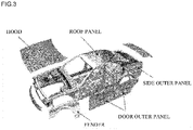
- a curved panel As examples of a panel having a curvature (referred to as "a curved panel”, hereinafter), there can be cited metal panels having a curved shape as a whole, such as a door outer panel, a roof panel, a hood, a fender, and a side outer panel of an automobile.
- metal panels having a curved shape as a whole such as a door outer panel, a roof panel, a hood, a fender, and a side outer panel of an automobile.
- a reduction in thickness of a steel sheet for example, used as a material of a curved panel has been in progress.
- the reduction in thickness of the steel sheet reduces stretch rigidity of the curved panel, so that in order to secure sufficient stretch rigidity, it is demanded to reinforce the curved panel.
- Patent Document 1 discloses a curved panel part which is formed by attaching an FRP (fiber reinforced plastic) sheet to a metal sheet.
- FRP fiber reinforced plastic
- Patent Document 2 discloses that a CFRP is bonded to a panel in a range of 1 to 30% of an area of the panel, to thereby disperse a load when pushing a center of the panel to an edge part of the panel on a side where the CFRP is bonded.
- Patent Document 3 discloses a structure including an inner layer made of glass fibers and surrounding a hollow core, an intermediate layer made of an FRP, and an outer layer made of glass fibers.
- Patent Document 4 discloses a panel structure of a door and the like of an automobile in which, under a reinforced resin layer made of an FRP, a bead forming member such as polyethylene foam whose width is narrower than that of the reinforced resin layer made of the FRP is provided, and a lower surface of a bottom portion of the reinforcement having a width wider than that of the bead forming member is bonded to a panel.
- Patent Document 5 discloses a roof structure for a vehicle including reinforcements made of an FRP and extending obliquely relative to the widthwise direction of the vehicle.
- Patent Document 6 discloses an FRP structure with a sandwich construction in which an FRP layer is disposed on a front side and a rear side, respectively, of a core material.
- Patent Document 7 discloses a structural member in which a reinforcement such as a carbon fiber unidirectional material or a carbon fiber cloth fabric having processed bonding portions in a projecting state, is bonded to a main structural material.
- Patent Document 1 discloses various shapes of the FRP sheet, but the formation of the FRP sheet in the shapes for the purpose of obtaining the reinforcing effect significantly increases manufacturing processes of the FRP sheet, which causes a reduction in productivity. Therefore, it is desirable to reinforce the curved panel by another method.
- Patent Document 2 the load when pushing the center of the panel is only dispersed, and thus it is difficult to fundamentally improve the stretch rigidity.
- the structure in Patent Document 3 has a structure in which the hollow core is necessarily provided in the inner layer, and thus there is a problem such that the structure cannot be applied when an inner space on the reinforcing side of the panel is limited, for example.
- Patent Document 6 In the structure of each of Patent Document 4 and Patent Document 5, only a part of the panel is reinforced, so that there is a limitation in the improvement of the stretch rigidity, and if the entire surface of the panel is reinforced, the weight as a whole is increased, which is a problem.
- the FRP structure of Patent Document 6 has a structure in which the core material is necessarily provided, and thus there is a problem such that the structure cannot be applied when an inner space on the reinforcing side of the panel is limited, for example.
- the projecting reinforcement is attached to the main structural material, and thus there is a problem such that the structure cannot be applied when an inner space is limited, for example.
- the present invention has been made in view of the above-described circumstances, and an object thereof is to provide a curved panel part capable of improving stretch rigidity without using a cloth fabric.
- a curved panel part including: a curved panel made of metal; and a reinforcement joined to the curved panel and made of a plurality of FRP layers including continuous fibers, in which each of the plurality of FRP layers has a single fiber direction, at least one layer out of the plurality of FRP layers has a fiber direction different from that of another layer, in the plurality of FRP layers, a proportion of layers having an angular difference in the fiber direction of 30° or more is 15% or more of all of the layers, and when calculating, by defining a maximum principal curvature direction of the curved panel as a 0° direction and a direction orthogonal to the 0° direction as a 90° direction, each of a 0° direction component and a 90° direction component regarding the fiber direction of each FRP layer of the reinforcement joined to the curved panel, by using a trigonometric function, a following expression (1) is satisfied. 580 ⁇ K ⁇ A ⁇ 4 + B /
- the reinforcement may be joined to the curved panel in its area of 70% or more.
- the reinforcement may be joined to the entire surface of the curved panel.
- a sheet thickness of the reinforcement may be 2.0 times or more a sheet thickness of the curved panel.
- the curved panel may be a hood or a roof panel of an automobile, and the reinforcement may be joined to a lower surface of the curved panel.
- the curved panel may be a fender, a door outer panel, or a side outer panel of an automobile, and the reinforcement may be joined to a vehicle-interior side surface of the curved panel.
- the curved panel may be a steel sheet with 440 MPa or more.
- the FRP may be a CFRP.
- the FRP may be a GFRP.
- a curved panel part 1 of the present embodiment is composed of a curved panel 2 made of metal, and a reinforcement 3 joined to the curved panel 2 and made of a plurality of FRP layers including continuous fibers.
- a material of the curved panel 2 made of metal is not particularly limited, a steel sheet, an aluminum alloy sheet, a magnesium alloy sheet, or the like is used, for example. From a viewpoint of improving stretch rigidity and dent resistance property, the curved panel 2 is preferably formed of a steel sheet with 440 MPa or more.
- the "curved panel” in this description includes not only a member whose entire panel surface is curved but also a member having a concave, a convex, and a planar portion partially but having a curved shape as a whole.
- An example of the curved panel 2 includes a part such as a hood, a roof panel, a fender, a door outer panel, or a side outer panel of an automobile, as illustrated in FIG. 3 . Further, the curved panel 2 is not limited to the automotive part, and it may also be another panel-shaped member.
- the curved panel 2 is obtained by processing a flat sheet. Therefore, at the stage of completing the manufacture of the curved panel 2, a shape and a material as a product are specified, and an application is also determined. Accordingly, it is possible to specify, out of a front-side surface and a rear-side surface of the curved panel 2, a surface to which a load from an out-of-plane direction is more frequently input, when used as a product.
- a load from an out-of-plane direction is more frequently input to the vehicle-exterior side surface than to the vehicle-interior side surface.
- the side on which the reinforcement 3 indicated by a dotted line is joined becomes a vehicle-interior side surface of a door outer panel.
- the surface to which the load from the out-of-plane direction is more frequently input as described above is referred to as a "load-input side surface".
- the curved surface 2a being a surface having a smaller curvature is the load-input side surface, but depending on the application of the curved panel 2, the curved surface 2b being a surface having a larger curvature becomes the load-input side surface in some cases.
- the reinforcement 3 is preferably joined to the curved surface 2b on the opposite side of the load-input side.
- the load-input side curved surface 2a is an upper surface (vehicle-exterior side surface) of the curved panel 2, and thus the reinforcement 3 is preferably joined to a lower surface (vehicle-interior side surface) of the curved panel 2.
- the load-input side curved surface 2a is a vehicle-exterior side surface of the curved panel 2, and thus the reinforcement 3 is preferably joined to a vehicle-interior side surface of the curved panel 2.
- the reinforcement 3 of the present embodiment is joined to the curved surface 2b of the curved panel 2 on the opposite side of the load-input side.
- a method of joining the reinforcement 3 to the curved panel 2 is not particularly limited, but they are joined by using an adhesive, for example.
- a sheet thickness of the reinforcement 3 namely, a total sheet thickness of the plurality of FRP layers is preferably 2.0 times or more a sheet thickness of the curved panel 2.
- the sheet thickness of the reinforcement 3 is more preferably 2.5 times or more the sheet thickness of the curved panel 2, and still more preferably 3.0 times or more the sheet thickness of the curved panel 2.
- the sheet thickness of the reinforcement 3 is preferably 10.0 times or less the sheet thickness of the curved panel 2, more preferably 7.5 times or less the sheet thickness of the curved panel 2, and still more preferably 5.0 times or less the sheet thickness of the curved panel 2.
- the FRP capable of being used as the reinforcement means a fiber reinforced plastic composed of a matrix resin and a reinforced fiber material contained in the matrix resin to be composite therewith.
- the reinforced fiber material for example, carbon fibers or glass fibers can be used.
- the reinforced fiber material boron fibers, silicon carbide fibers, aramid fibers, or the like can be used.
- a reinforced fiber base material serving as a base material of the reinforced fiber material it is possible to use a unidirectional reinforced fiber base material (UD material), or the like, for example.
- UD material unidirectional reinforced fiber base material
- the CFRP is the FRP using the carbon fibers as the reinforced fiber material.
- the carbon fibers for example, PAN-based ones or pitch-based ones can be used.
- the carbon fibers of the CFRP are preferably pitch-based carbon fibers with high elastic modulus. According to the reinforcement 3 using the pitch-based carbon fibers, it is possible to obtain a higher reaction force, and improve the stretch rigidity.
- the GFRP is the FRP using the glass fibers as the reinforced fiber material.
- the glass fibers are inferior in a mechanical property to the carbon fibers, but can suppress electrolytic corrosion of a metal member.
- thermosetting resin there can be cited an epoxy resin, an unsaturated polyester resin, a vinylester resin, and the like.
- thermoplastic resin there can be cited polyolefin (polyethylene, polypropylene, or the like) and an acid-modified product thereof, a polyamide resin such as nylon 6 and nylon 66, thermoplastic aromatic polyester such as polyethylene terephthalate and polybutyrene terephthalate, polycarbonate, polyethersulfone, polyphenyleneether and a modified product thereof, polyarylate, polyetherketone, polyetheretherketone, polyetherketoneketone, vinyl chloride, a styrene-based resin such as polystyrene, a phenoxy resin, and the like.
- the matrix resin may be formed of a plurality of kinds of resin materials.
- thermoplastic resin As the matrix resin, from a viewpoint of workability and productivity, it is preferable to use the thermoplastic resin as the matrix resin.
- the phenoxy resin As the matrix resin, it is possible to increase a density of the reinforced fiber material. Further, the phenoxy resin has heat resistance nearly equal to that of the epoxy resin because a molecular structure thereof closely resembles that of the epoxy resin being the thermosetting resin.
- further adding a curing component also enables application to a high-temperature environment. When the curing component is added, its addition amount only needs to be appropriately determined in consideration of impregnating ability into the reinforced fiber material, brittleness of the FRP, tact time, workability, and so on.
- an adhesive resin layer (illustration thereof is omitted) may be provided between the FRP material and the metal member (the curved panel 2 in the present embodiment) to join the FRP material and the metal member by using the adhesive resin layer.
- the kind of adhesive resin composition forming the adhesive resin layer is not particularly limited.
- the adhesive resin composition may be either of the thermosetting resin and the thermoplastic resin.
- the kinds of the thermosetting resin and the thermoplastic resin are not particularly limited.
- the thermoplastic resin there can be used one or more kinds selected from polyolefin and an acid-modified product thereof, polystyrene, polymethyl methacrylate, an AS resin, an ABS resin, thermoplastic aromatic polyester such as polyethylene terephthalate or polybutyrene terephthalate, polycarbonate, polyimide, polyamide, polyamide-imide, polyetherimide, polyethersulfone, polyphenyleneether and a modified product thereof, polyphenylene sulfide, polyoxymethylene, polyarylate, polyetherketone, polyetheretherketone, polyetherketoneketone, and the like.
- the thermosetting resin for example, there can be used one or more kinds selected from an epoxy resin, a vinylester resin, a phenolic resin
- the adhesive resin composition can be appropriately selected according to properties of the matrix resin composing the FRP material, properties of the reinforcement, or properties of the metal member.
- a resin having a functional group with polarity or a resin subjected to acid modification or the like is used as the adhesive resin layer, thereby improving adhesion properties.
- the FRP material bond to the metal member by using the aforementioned adhesive resin layer, it is possible to improve adhesiveness between the FRP material and the metal member. Accordingly, it is possible to improve deformation followability of the FRP material when a load is input to the metal member. In this case, it becomes possible to more securely exhibit the effect of the FRP material with respect to a deformable body of the metal member.
- a form of the adhesive resin composition used for forming the adhesive resin layer can be, for example, powder, a liquid such as varnish, or a solid such as a film.
- the crosslinkable adhesive resin composition may be formed. This improves heat resistance of the adhesive resin composition, which thus enables the application under a high-temperature environment.
- a crosslinking curable resin for example, a bifunctional or higher epoxy resin or a crystalline epoxy resin can be used.
- the crosslinking agent an amine, an acid anhydride, or the like can be used.
- other additives such as various kinds of rubber, an inorganic filler, and a solvent may be mixed in a range not to impair its adhesion properties and physical properties.
- the FRP material being composite with the metal member can be achieved by various methods.
- the FRP or a prepreg for FRP molding being a precursor thereof which serves as the FRP material
- the metal member are bonded by the aforementioned adhesive resin composition to solidify (or cure) the adhesive resin composition, thereby obtaining the FRP material being composite with the metal member.
- performing thermocompression bonding allows the FRP material and the metal member to be made composite with each other.
- the bonding of the aforementioned FRP or prepreg for FRP molding to the metal member can be performed before molding of parts, during molding thereof, or after molding thereof.
- the FRP or the prepreg for FRP molding may be bonded to the metal member.
- the workpiece to which the FRP material is bonded may be molded to obtain the metal member being composite therewith.
- the matrix resin of the FRP material is the thermoplastic resin
- a portion to which the FRP material is bonded can also be subjected to molding such as bending.
- composite integrated molding in which a thermocompression bonding process and a molding process are integrated may be performed.
- the joining method of the FRP material and the metal member is not limited to the bonding by using the aforementioned adhesive resin layer.
- the FRP material and the metal member may be mechanically joined.
- fastening holes may be formed at positions where the FRP material and the metal member correspond to each other to join the FRP material and the metal member by fastening them through the holes by a fastening means such as bolts or rivets.
- the FRP material and the metal member may be joined by well-known joining means.
- the FRP material and the metal member may be joined in a complex manner by a plurality of joining means.
- the bonding by using the adhesive resin layer and the fastening by the fastening means may be used in a complex manner.
- the metal member according to the present invention may be a hot-rolled steel sheet or a cold-rolled steel sheet, but those steel sheets may also be plated. This improves corrosion resistance.
- plating is more suitable.
- the kind of plating is not particularly limited, and well-known plating can be used.
- a plated steel sheet steel material
- a sheet thickness of the metal member is not necessarily limited in particular, it is often about 0.60 to 3.2 mm when used as a member for automobile, for example.
- a surface of the metal member may be covered by a coating film through treatment called conversion treatment.
- conversion treatment generally well-known conversion treatment can be used.
- the conversion treatment there can be used zinc phosphate treatment, chromate treatment, chromate-free treatment, or the like.
- the above-described coating film may also be a well-known resin coating film.
- the metal member may be subjected to generally well-known coating.
- coating well-known resins can be used.
- the coating there can be used coating in which an epoxy resin, a urethane resin, an acrylic resin, a polyester resin, a fluorine-based resin, or the like is used as a main resin.
- generally well-known pigments may be added according to need.
- the coating may be clear coating in which the pigment is not added. Such coating may be performed on the metal member in advance before being composite with the FRP material, or may be performed on the metal member after being composite with the FRP material.
- the FRP material may be composite therewith to thereafter further perform the coating.
- a coating material used for the coating may be a solvent-based coating material, a water-based coating material, a powder coating material, or the like.
- As an execution method of the coating generally well-known methods can be applied.
- the execution method of the coating there can be used electrodeposition coating, spray coating, electrostatic coating, dip coating, or the like. Because the electrodeposition coating is suitable for covering an end face and a gap portion of the metal member, it is excellent in corrosion resistance after coating.
- the generally well-known conversion treatment such as zinc phosphate treatment or zirconia treatment is performed on the surface of the metal member before coating, thereby improving coating film adhesiveness.
- FIG. 4 is a view for explaining a layer structure of the reinforcement 3.
- Each of the plurality of FRP layers composing the reinforcement 3 has a single fiber direction, and at least one layer out of the plurality of FRP layers has a fiber direction different from that of another layer.
- a maximum principal curvature direction of the curved panel 2 is defined as a "0° direction”
- a direction orthogonal to the 0° direction when facing the curved surface regarding which the 0° direction is defined is defined as a "90° direction”.
- 0° direction a direction orthogonal to the 0° direction when facing the curved surface regarding which the 0° direction is defined
- the FRP has a six-layer structure, and out of the plurality of FRP layers, four layers close to the curved surface 2b of the curved panel 2 have continuous fibers oriented in the 0° direction, and the rest of the two layers have continuous fibers oriented in the 90° direction.
- a layer having continuous fibers oriented in a single specific direction is referred to as an "oriented layer”.
- a layer having fibers oriented in the 0° direction is referred to as a 0° oriented layer
- a layer having fibers oriented in the 90° direction is referred to as a 90° oriented layer.
- the reinforcement 3 illustrated in FIG. 4 has four 0° oriented layers 3a, and two 90° oriented layers.
- a " ⁇ ° oriented layer” also includes an oriented layer composed of continuous fibers oriented in ⁇ +5°.
- the "0° oriented layer” includes not only an FRP layer having continuous fibers whose fiber direction is strictly oriented in the 0° direction but also an oriented layer including continuous fibers oriented in -5° to 5° relative to the 0° direction.
- the fiber direction of the oriented layer can be identified by observing and analyzing a fiber-reinforced resin material by using a micro-focus X-ray CT (X-ray Computed Tomography).
- the total number of the layers composing the reinforcement 3 is not particularly limited, and is appropriately changed according to the shape of the curved panel 2, the required stretch rigidity, and so on.
- the size of the reinforcement 3, the sheet thickness of each layer of the FRP, a joint position of the reinforcement 3 with respect to the curved panel 2, and so on are also not limited in particular, and are appropriately changed according to the shape of the curved panel 2, the required stretch rigidity, and so on.
- the inventors of the present application evaluated the stretch rigidity of a member in which a material formed in a manner that fibers in two or more directions are woven in one layer of an FRP, such as the carbon fiber cloth fabric in Patent Document 7, is attached to a curved panel, an effect of improving the stretch rigidity was small. Although the reason thereof is unclear, the cloth fabric has wavy fibers, which may exert an influence.
- the present invention was created as a result of research, based on the evaluation result, regarding the improvement of stretch rigidity by stacking FRP layers each having a single fiber direction, without using the cloth fabric. For this reason, the reinforcement according to the present invention is composed of a plurality of FRP layers, and each of the plurality of FRP layers has a single fiber direction.
- the inventors found out that, in order to improve the stretch rigidity, it is preferable that the fiber directions of the plurality of FRP layers are not oriented in a single direction, there exists an FRP layer having an angular difference in the fiber direction of 30° or more, and a proportion of the FRP layers having an angular difference in the fiber direction of 30° or more is set to 15% or more of all of the FRP layers.
- a value of "a proportion of the FRP layers having an angular difference in a fiber direction of 30° or more relative to all of the layers" changes depending on a fiber direction set as a reference among a plurality of fiber directions, but in this description, it is set that the aforementioned proportions when the respective fiber directions are set as references are respectively calculated, and a value of the smallest proportion is used.
- the calculation based on the above-described method is performed when the thicknesses of the respective FRP layers and the densities of FRP fibers are substantially the same, but when the thicknesses of the respective layers and the densities are different, the aforementioned proportion is calculated by setting the thicknesses of the respective layers and the densities as weights.
- the angular difference of the FRP layer is preferably larger, and is preferably 40° or more, 50° or more, or 60° or more.
- An upper limit of the angular difference is 90°, as a matter of course.
- the proportion of FRP layers each having a fiber direction with a predetermined angular difference or more relative to all of the layers is preferably larger, and is preferably 20% or more, 25% or more, or 30% or more. However, an upper limit of the proportion is 50%.
- the curved panel part 1 is configured as described above.
- a load F from an out-of-plane direction is input to the load-input side curved surface 2a of the curved panel 2
- a substantially circular strain is generated in a periphery of a load-input position.
- the present inventor found out that, in such a case, the stretch rigidity is effectively improved by using the curved panel part 1 to which the reinforcement 3 in which at least one layer out of the plurality of FRP layers has a fiber direction different from that of another layer, a proportion of FRP layers having an angular difference in the fiber direction of 30° or more is 15% or more of all of the layers, and a following expression (1) is satisfied, is joined. 580 ⁇ K ⁇ A ⁇ 4 + B / C + D
- the proportions of the 0° direction component (a component parallel to the maximum principal curvature direction of the curved panel 2) and the 90° direction component (a component parallel to a direction perpendicular to the maximum principal curvature direction of the curved panel 2) are calculated as follows.
- an example will be described in which two kinds of fiber directions are included in the FRP layers as a whole composing the reinforcement joined to the curved panel 2.
- FIG. 5 illustrates an FRP layer having a first fiber direction whose angle (acute angle) made with the 0° direction is ⁇ 1
- FIG. 6 illustrates an FRP layer having a second fiber direction whose angle (acute angle) made with the 0° direction is ⁇ 2 .
- the first fiber direction and the second fiber direction are mutually different directions.
- the "90° direction component" in this description has an absolute value of the 90° direction component calculated by performing, with the use of a trigonometric function, component decomposition on the fiber direction of the FRP layer into the 0° direction component and the 90° direction component.
- the angle ⁇ 1 is subjected to component decomposition to calculate the 0° direction component and the 90° direction component.
- the angle ⁇ 1 of that layer is also subjected to component decomposition to calculate the 0° direction component and the 90° direction component, in a similar manner.
- the angle ⁇ 2 is subjected to component decomposition to calculate the 0° direction component and the 90° direction component.
- the angle ⁇ 2 of that layer is also subjected to component decomposition to calculate the 0° direction component and the 90° direction component, in a similar manner.
- the 0° direction component and the 90° direction component are calculated regarding each of the layers, and then the 0° direction components of the respective layers are totalized, resulting in that the 0° direction component of the layers as a whole in the expression (1) ("C" in the expression (1)) is calculated.
- the 90° direction component of the layers as a whole in the expression (1) (“D" in the expression (1)) is calculated.
- an absolute value of cos30° is the 0° direction component
- an absolute value of sin30° is the 90° direction component.
- the 0° direction component and the 90° direction component regarding the first fiber direction when the angle ⁇ 1 is 30° are about 0.866 and 0.5, respectively.
- an absolute value of cos-60° is the 0° direction component
- an absolute value of sin-60° is the 90° direction component.
- the 0° direction component and the 90° direction component regarding the second fiber direction when the angle ⁇ 2 is -60° are 0.5 and about 0.866, respectively.
- the 0° direction component of the layers as a whole is about 4.46 (0.866 ⁇ 4 + 0.5 ⁇ 2)
- the 90° direction component of the layers as a whole is about 3.73 (0.5 ⁇ 4 + 0.866 ⁇ 2).
- the total value of the 0° direction component and the total value of the 90° direction component are calculated in the manner as described above. Note that when the fiber direction is the 0° direction, a value of the 0° direction component is cos0°, namely, 1, and a value of the 90° direction component is sin0°, namely, 0. Further, when the fiber direction is the 90° direction, a value of the 0° direction component is cos90°, namely, 0, and a value of the 90° direction component is sin90°, namely, 1.
- the calculation based on the above-described method is performed when the thicknesses of the respective FRP layers and the densities of FRP fibers are substantially the same, but when the thicknesses of the respective layers and the densities are different, the aforementioned proportion is calculated by setting the thicknesses of the respective layers and the densities as weights. For example, when a value of the 0° direction component of a k-th layer from the joint side out of the FRP of n layers is set to x k , and a thickness of the layer is set to t k , the total value of the 0° direction component of the layers as a whole is obtained by x 1 ⁇ t 1 + ⁇ + x n ⁇ t n . The total value of the 90° direction component is also obtained in a similar manner.
- an FRP layer positioned on a joint side with respect to the curved panel 2, relative to a center T c of the sheet thickness of the reinforcement 3 (namely, the total sheet thickness of respective layers), is referred to as "a layer positioned on an inner side of the center T c of the sheet thickness", and an FRP layer positioned on the opposite side of the joint side, is referred to as "a layer positioned on an outer side of the center T c of the sheet thickness”.
- the 0° direction component of the FRP layers positioned on the outer side of the center of the sheet thickness of the reinforcement 3 in the expression (1) is the total value of the 0° direction components of the three layers on the lower side out of the six FRP layers
- the 0° direction component of the FRP layers positioned on the inner side of the center of the sheet thickness of the reinforcement 3 in the expression (1) is the total value of the 0° direction components of the three layers on the upper side out of the six FRP layers.
- “K” in the expression (1) is a value obtained of dividing "1" by a curvature radius in the 0° direction of the curved panel 2, and corresponds to a maximum principal curvature.
- “K” in the expression (1) is an index indicating what kind of shape the curved panel 2 has, so that in the explanation hereinbelow, "K” in the expression (1) is referred to as a shape index K.
- a shape index K In order to improve the stretch rigidity of the curved panel part 1, it is important to define the fiber direction of each FRP layer, but the influence of the fiber direction of the FRP exerted on the stretch rigidity of the curved panel part 1 becomes different depending also on the shape of the curved panel 2.
- the condition satisfying this requirement is the expression (1).
- a proportion of FRP layers having an angular difference in the fiber direction of 30° or more is 15% or more of all of the layers, and the expression (1) is satisfied, it is possible to improve the stretch rigidity.
- the reinforcement 3 illustrated in FIG. 7 has a 90° oriented layer 3b, a 45° oriented layer 3c, a -45° oriented layer 3d, a 0° oriented layer 3a, the 90° oriented layer 3b, and the 0° oriented layer 3a, in the order from the curved surface 2b of the curved panel 2.
- the reinforcement 3 is preferably joined to the curved surface 2b on the opposite side of the curved surface 2a.
- the curved panel 2 is a part such as a door outer panel, a roof panel, a hood, a fender, or a side outer panel of an automobile
- the load F from the out-of-plane direction is input to the load-input side curved surface 2a of the curved panel 2, so that a tensile stress on the curved surface 2b side of the curved panel 2 becomes large.
- the reinforcement 3 is preferably joined to the entire surface of the curved panel 2, as illustrated in FIG. 8 .
- the reinforcement 3 is preferably joined to the entire surface of the curved panel 2, as illustrated in FIG. 8 .
- the reinforcement 3 is preferably joined to the entire surface of the curved panel 2, it becomes possible to obtain a stiffening effect by the reinforcement 3 even if a load is input at any position of the curved panel 2.
- the reinforcement 3 is not joined to the entire surface of the curved panel 2, it is preferably joined to the curved panel 2 in its area of 70% or more.
- the reinforcement 3 is more preferably joined to the curved panel 2 in its area of 80% or more, and still more preferably joined to the curved panel 2 in its area of 90% or more.
- the stiffening effect to be exhibited becomes larger than that of the FRP sheet in Patent Document 1.
- the stiffening effect equal to the stiffening effect in Patent Document 1 it is also possible to reduce a weight of the curved panel part 1 by reducing the sheet thickness of the reinforcement 3, for example.
- the reinforcement 3 is joined to the entire surface of the curved panel 2, it is possible to realize a reduction in weight of the panel part and secure sufficient stretch rigidity, when compared to a conventional case where a plurality of FRP sheets are joined to the entire panel.
- the stretch rigidity of the curved panel part 1 was evaluated by a method illustrated in FIG. 9 .
- the stretch rigidity was evaluated by pushing an indenter 10 having a semispherical shape of R50 into a center portion of the curved surface 2a of the curved panel 2 of the curved panel part 1 in which the reinforcement 3 was joined to the curved surface 2b on the opposite side of the load-input side curved surface 2a of the curved panel 2.
- the stretch rigidity is evaluated by the magnitude of load required when pushing the indenter 10 by 2 mm (referred to as "load at 2 mm stroke", hereinafter), and the curved panel part 1 having a larger load at 2 mm stroke is a member which has higher stretch rigidity and which is more unlikely to be deformed.
- the curved panel 2 is a steel sheet with tensile strength of 590 MPa
- the reinforcement 3 is a member having a plurality of FRP layers with a Young's modulus of 102 GPa.
- curved panel 2 three kinds thereof having different shape indices K as follows were prepared, and the stretch rigidity of each curved panel part was evaluated.
- the load at 2 mm stroke of each of CASE a3 to CASE a20 in which the reinforcement is joined to the curved panel becomes larger than the load at 2 mm stroke of each of CASE a1 and CASE a2 using only the curved panel, and thus it can be confirmed that the stretch rigidity is improved when the reinforcement is joined to the curved panel.
- the reinforcement of each of CASE a4 to CASE a10 has a structure in which six CFRP layers each having a thickness of 0.20 mm are stacked. Although the weight of the CFRP with a sheet thickness of 1.20 mm (0.20 mm ⁇ 6) is about the same as the weight of an aluminum sheet of 0.70 mm used as the reinforcement of CASE a3, the load at 2 mm stroke of each of CASE a4 to CASE a9 is smaller than the load at 2 mm stroke of CASE a3, and thus the stretch rigidity of each of CASE a4 to CASE a9 is inferior to that of CASE a3.
- each of CASE a12 to a20 using the CFRP having two or three fiber directions satisfies the expression (1), similarly to CASE a4 to CASE a9, but the load at 2 mm stroke of each of CASE a12 to a20 is larger than that of each of CASE a3 to CASE a9, and thus the stretch rigidity of each of CASE a12 to a20 is improved.
- the stretch rigidity as the curved panel part is improved.
- the stretch rigidity is improved more than that of CASE a3 using the aluminum sheet which is advantageous for the reduction in weight.
- the curved panel part of each of CASE a12 to a20 being invention examples is excellent in mass efficiency of the stretch rigidity, and can realize both the stretch rigidity and the reduction in weight at high level.
- the stretch rigidity is improved more than that of CASE c1 using the aluminum sheet which is advantageous for the reduction in weight. Therefore, the curved panel part of each of CASE b5 to b10 and CASE c5, c9, and c10 also has a structure excellent in the mass efficiency of the stretch rigidity, similarly to the above-described CASE a12 to a20.
- the curved panel part according to the present invention is a member capable of realizing both the stretch rigidity and the reduction in weight at high level, regardless of the shape index K of the curved panel.
- the size (area) of the reinforcement in CASE a13 and that in CASE a20 are mutually different.
- the reinforcement in CASE a13, the reinforcement is joined to the region of the curved panel in its area of 100%, similarly to the other Examples except for CASE A20, and in CASE a20, the reinforcement is joined to the region of the curved panel in its area of 80%.
- the stretch rigidity is evaluated in CASE a13 and CASE a20 under the same condition except for the condition regarding the size of the reinforcement, the load at 2 mm stroke took a high value in both CASE a13 and CASE a20. Based on this result, it can be confirmed that even if the reinforcement is not joined to the entire surface of the curved panel, it is possible to sufficiently obtain the effect of improving the stretch rigidity.
- the stretch rigidity is improved.
- the total number of the plurality of FRP layers is not particularly limited.
- a material made of the FRP there is a material formed in a manner that fibers in two or more directions are woven in one layer of the FRP (so-called a cloth fabric), and when the stretch rigidity regarding the cloth fabric was evaluated based on the method in FIG. 9 , the effect of improving the stretch rigidity was small.
- the present invention can be used as a structure of a door outer panel, a roof panel, a hood, a fender, a side outer panel, or the like of an automobile.
Landscapes
- Engineering & Computer Science (AREA)
- Mechanical Engineering (AREA)
- Chemical & Material Sciences (AREA)
- Combustion & Propulsion (AREA)
- Transportation (AREA)
- Composite Materials (AREA)
- Architecture (AREA)
- Structural Engineering (AREA)
- Textile Engineering (AREA)
- Laminated Bodies (AREA)
- Body Structure For Vehicles (AREA)
- Superstructure Of Vehicle (AREA)
Abstract
Description
- The present invention relates to a structure of a panel having a curvature.
- As examples of a panel having a curvature (referred to as "a curved panel", hereinafter), there can be cited metal panels having a curved shape as a whole, such as a door outer panel, a roof panel, a hood, a fender, and a side outer panel of an automobile. In development of automobiles, for realizing a reduction in weight for the purpose of improving fuel efficiency, a reduction in thickness of a steel sheet, for example, used as a material of a curved panel has been in progress. On the other hand, the reduction in thickness of the steel sheet reduces stretch rigidity of the curved panel, so that in order to secure sufficient stretch rigidity, it is demanded to reinforce the curved panel.
- As a structure of reinforcing a curved panel,
Patent Document 1 discloses a curved panel part which is formed by attaching an FRP (fiber reinforced plastic) sheet to a metal sheet. In the curved panel part ofPatent Document 1, a shape of the FRP sheet is appropriately changed, to thereby improve a restoration property when the curved panel is deformed.Patent Document 2 discloses that a CFRP is bonded to a panel in a range of 1 to 30% of an area of the panel, to thereby disperse a load when pushing a center of the panel to an edge part of the panel on a side where the CFRP is bonded.Patent Document 3 discloses a structure including an inner layer made of glass fibers and surrounding a hollow core, an intermediate layer made of an FRP, and an outer layer made of glass fibers. Patent Document 4 discloses a panel structure of a door and the like of an automobile in which, under a reinforced resin layer made of an FRP, a bead forming member such as polyethylene foam whose width is narrower than that of the reinforced resin layer made of the FRP is provided, and a lower surface of a bottom portion of the reinforcement having a width wider than that of the bead forming member is bonded to a panel. Patent Document 5 discloses a roof structure for a vehicle including reinforcements made of an FRP and extending obliquely relative to the widthwise direction of the vehicle. Patent Document 6 discloses an FRP structure with a sandwich construction in which an FRP layer is disposed on a front side and a rear side, respectively, of a core material. Patent Document 7 discloses a structural member in which a reinforcement such as a carbon fiber unidirectional material or a carbon fiber cloth fabric having processed bonding portions in a projecting state, is bonded to a main structural material. -
- Patent Document 1:
Japanese Laid-open Patent Publication No. 2001-253371 - Patent Document 2:
Japanese Laid-open Patent Publication No. 2018-016171 - Patent Document 3:
Japanese Laid-open Patent Publication No. 2003-291232 - Patent Document 4:
Japanese Laid-open Patent Publication No. S57-151357 - Patent Document 5: International Publication Pamphlet No.
WO 2014/034586 - Patent Document 6:
Japanese Laid-open Patent Publication No. 2008-213437 - Patent Document 7:
Japanese Laid-open Patent Publication No. 2009-166408 -
Patent Document 1 discloses various shapes of the FRP sheet, but the formation of the FRP sheet in the shapes for the purpose of obtaining the reinforcing effect significantly increases manufacturing processes of the FRP sheet, which causes a reduction in productivity. Therefore, it is desirable to reinforce the curved panel by another method. InPatent Document 2, the load when pushing the center of the panel is only dispersed, and thus it is difficult to fundamentally improve the stretch rigidity. The structure inPatent Document 3 has a structure in which the hollow core is necessarily provided in the inner layer, and thus there is a problem such that the structure cannot be applied when an inner space on the reinforcing side of the panel is limited, for example. In the structure of each of Patent Document 4 and Patent Document 5, only a part of the panel is reinforced, so that there is a limitation in the improvement of the stretch rigidity, and if the entire surface of the panel is reinforced, the weight as a whole is increased, which is a problem. The FRP structure of Patent Document 6 has a structure in which the core material is necessarily provided, and thus there is a problem such that the structure cannot be applied when an inner space on the reinforcing side of the panel is limited, for example. In the structure of Patent Document 7, the projecting reinforcement is attached to the main structural material, and thus there is a problem such that the structure cannot be applied when an inner space is limited, for example. - The present invention has been made in view of the above-described circumstances, and an object thereof is to provide a curved panel part capable of improving stretch rigidity without using a cloth fabric.
- One aspect of the present invention solving the above-described problems is a curved panel part including: a curved panel made of metal; and a reinforcement joined to the curved panel and made of a plurality of FRP layers including continuous fibers, in which each of the plurality of FRP layers has a single fiber direction, at least one layer out of the plurality of FRP layers has a fiber direction different from that of another layer, in the plurality of FRP layers, a proportion of layers having an angular difference in the fiber direction of 30° or more is 15% or more of all of the layers, and when calculating, by defining a maximum principal curvature direction of the curved panel as a 0° direction and a direction orthogonal to the 0° direction as a 90° direction, each of a 0° direction component and a 90° direction component regarding the fiber direction of each FRP layer of the reinforcement joined to the curved panel, by using a trigonometric function, a following expression (1) is satisfied.

- A: the 0° direction component of the FRP layers positioned on an outer side of a center of a sheet thickness of the reinforcement
- B: the 0° direction component of the FRP layers positioned on an inner side of the center of the sheet thickness of the reinforcement
- C: the 0° direction component of the plurality of FRP layers as a whole
- D: the 90° direction component of the plurality of FRP layers as a whole
- K: 1 / curvature radius in the 0° direction (mm)
- The reinforcement may be joined to the curved panel in its area of 70% or more. The reinforcement may be joined to the entire surface of the curved panel. A sheet thickness of the reinforcement may be 2.0 times or more a sheet thickness of the curved panel.
- The curved panel may be a hood or a roof panel of an automobile, and the reinforcement may be joined to a lower surface of the curved panel. The curved panel may be a fender, a door outer panel, or a side outer panel of an automobile, and the reinforcement may be joined to a vehicle-interior side surface of the curved panel.
- The curved panel may be a steel sheet with 440 MPa or more. The FRP may be a CFRP. The FRP may be a GFRP.
- According to the present invention, it is possible to provide a curved panel part capable of improving stretch rigidity without using a cloth fabric.
-
-
FIG. 1 is a perspective view illustrating a schematic configuration of a curved panel part according to an embodiment of the present invention. -
FIG. 2 is a perspective view in which the curved panel part inFIG. 1 is seen from a rear side. -
FIG. 3 is a view illustrating an example of a vehicle body structure of an automobile. -
FIG. 4 is a view for explaining a layer structure of a reinforcement according to the present embodiment. -
FIG. 5 is a view for explaining a calculation method of a 0° direction component and a 90° direction component of a fiber direction. -
FIG. 6 is a view for explaining a calculation method of a 0° direction component and a 90° direction component of a fiber direction. -
FIG. 7 is a view illustrating an example of a layer structure of a reinforcement according to the present embodiment. -
FIG. 8 is a view illustrating an example of joint between a curved panel and a reinforcement. -
FIG. 9 is a view illustrating a condition for evaluating stretch rigidity. - Hereinafter, an embodiment of the present invention will be described while referring to the drawings. Note that in this description and the drawings, elements having substantially the same functional configuration are denoted by the same codes to omit duplicated explanation.
- As illustrated in
FIG. 1 and FIG. 2 , acurved panel part 1 of the present embodiment is composed of acurved panel 2 made of metal, and areinforcement 3 joined to thecurved panel 2 and made of a plurality of FRP layers including continuous fibers. Although a material of thecurved panel 2 made of metal is not particularly limited, a steel sheet, an aluminum alloy sheet, a magnesium alloy sheet, or the like is used, for example. From a viewpoint of improving stretch rigidity and dent resistance property, thecurved panel 2 is preferably formed of a steel sheet with 440 MPa or more. The "curved panel" in this description includes not only a member whose entire panel surface is curved but also a member having a concave, a convex, and a planar portion partially but having a curved shape as a whole. An example of thecurved panel 2 includes a part such as a hood, a roof panel, a fender, a door outer panel, or a side outer panel of an automobile, as illustrated inFIG. 3 . Further, thecurved panel 2 is not limited to the automotive part, and it may also be another panel-shaped member. - Note that the
curved panel 2 is obtained by processing a flat sheet. Therefore, at the stage of completing the manufacture of thecurved panel 2, a shape and a material as a product are specified, and an application is also determined. Accordingly, it is possible to specify, out of a front-side surface and a rear-side surface of thecurved panel 2, a surface to which a load from an out-of-plane direction is more frequently input, when used as a product. For example, in a case of a door outer panel of an automobile, if a front-side surface is set to a vehicle-exterior side surface, and a rear-side surface is set to a vehicle-interior side surface, a load from an out-of-plane direction is more frequently input to the vehicle-exterior side surface than to the vehicle-interior side surface. Specifically, in the example illustrated inFIG. 1 , the side on which thereinforcement 3 indicated by a dotted line is joined, becomes a vehicle-interior side surface of a door outer panel. In this description, out of the front-side surface and the rear-side surface of thecurved panel 2, the surface to which the load from the out-of-plane direction is more frequently input as described above, is referred to as a "load-input side surface". In the present embodiment, explanation will be made hereinbelow by assuming that, out ofcurved surfaces curved panel 2, thecurved surface 2a being a surface having a smaller curvature is the load-input side surface, but depending on the application of thecurved panel 2, thecurved surface 2b being a surface having a larger curvature becomes the load-input side surface in some cases. - From a viewpoint of effectively improving the stretch rigidity, the
reinforcement 3 is preferably joined to thecurved surface 2b on the opposite side of the load-input side. When thecurved panel 2 is, for example, a hood or a roof panel of an automobile, the load-input side curvedsurface 2a is an upper surface (vehicle-exterior side surface) of thecurved panel 2, and thus thereinforcement 3 is preferably joined to a lower surface (vehicle-interior side surface) of thecurved panel 2. When thecurved panel 2 is, for example, a fender, a door outer panel, or a side outer panel of an automobile, the load-input side curvedsurface 2a is a vehicle-exterior side surface of thecurved panel 2, and thus thereinforcement 3 is preferably joined to a vehicle-interior side surface of thecurved panel 2. - The
reinforcement 3 of the present embodiment is joined to thecurved surface 2b of thecurved panel 2 on the opposite side of the load-input side. A method of joining thereinforcement 3 to thecurved panel 2 is not particularly limited, but they are joined by using an adhesive, for example. From a viewpoint of effectively improving the stretch rigidity of thecurved panel part 1, a sheet thickness of thereinforcement 3, namely, a total sheet thickness of the plurality of FRP layers is preferably 2.0 times or more a sheet thickness of thecurved panel 2. The sheet thickness of thereinforcement 3 is more preferably 2.5 times or more the sheet thickness of thecurved panel 2, and still more preferably 3.0 times or more the sheet thickness of thecurved panel 2. Although an upper limit of the sheet thickness of thereinforcement 3 is appropriately set from a viewpoint of required stretch rigidity, weight, and so on of thecurved panel part 1, the sheet thickness of the reinforcement is preferably 10.0 times or less the sheet thickness of thecurved panel 2, more preferably 7.5 times or less the sheet thickness of thecurved panel 2, and still more preferably 5.0 times or less the sheet thickness of thecurved panel 2. - The FRP capable of being used as the reinforcement (also referred to as an FRP material) means a fiber reinforced plastic composed of a matrix resin and a reinforced fiber material contained in the matrix resin to be composite therewith.
- As the reinforced fiber material, for example, carbon fibers or glass fibers can be used. Other than the above, as the reinforced fiber material, boron fibers, silicon carbide fibers, aramid fibers, or the like can be used. In the FRP used for the FRP material, as a reinforced fiber base material serving as a base material of the reinforced fiber material, it is possible to use a unidirectional reinforced fiber base material (UD material), or the like, for example. These reinforced fiber base materials can be appropriately selected according to the necessity for orientation of the reinforced fiber material.
- The CFRP is the FRP using the carbon fibers as the reinforced fiber material. As the carbon fibers, for example, PAN-based ones or pitch-based ones can be used. The carbon fibers of the CFRP are preferably pitch-based carbon fibers with high elastic modulus. According to the
reinforcement 3 using the pitch-based carbon fibers, it is possible to obtain a higher reaction force, and improve the stretch rigidity. - The GFRP is the FRP using the glass fibers as the reinforced fiber material. The glass fibers are inferior in a mechanical property to the carbon fibers, but can suppress electrolytic corrosion of a metal member.
- As the matrix resin used for the FRP, either of a thermosetting resin and a thermoplastic resin can be used. As the thermosetting resin, there can be cited an epoxy resin, an unsaturated polyester resin, a vinylester resin, and the like. As the thermoplastic resin, there can be cited polyolefin (polyethylene, polypropylene, or the like) and an acid-modified product thereof, a polyamide resin such as nylon 6 and nylon 66, thermoplastic aromatic polyester such as polyethylene terephthalate and polybutyrene terephthalate, polycarbonate, polyethersulfone, polyphenyleneether and a modified product thereof, polyarylate, polyetherketone, polyetheretherketone, polyetherketoneketone, vinyl chloride, a styrene-based resin such as polystyrene, a phenoxy resin, and the like. Note that the matrix resin may be formed of a plurality of kinds of resin materials.
- In consideration of application to the metal member, from a viewpoint of workability and productivity, it is preferable to use the thermoplastic resin as the matrix resin. Moreover, by using the phenoxy resin as the matrix resin, it is possible to increase a density of the reinforced fiber material. Further, the phenoxy resin has heat resistance nearly equal to that of the epoxy resin because a molecular structure thereof closely resembles that of the epoxy resin being the thermosetting resin. Besides, further adding a curing component also enables application to a high-temperature environment. When the curing component is added, its addition amount only needs to be appropriately determined in consideration of impregnating ability into the reinforced fiber material, brittleness of the FRP, tact time, workability, and so on.
- When the reinforcement is formed by the FRP material or the like, an adhesive resin layer (illustration thereof is omitted) may be provided between the FRP material and the metal member (the
curved panel 2 in the present embodiment) to join the FRP material and the metal member by using the adhesive resin layer. - The kind of adhesive resin composition forming the adhesive resin layer is not particularly limited. For example, the adhesive resin composition may be either of the thermosetting resin and the thermoplastic resin. The kinds of the thermosetting resin and the thermoplastic resin are not particularly limited. For example, as the thermoplastic resin, there can be used one or more kinds selected from polyolefin and an acid-modified product thereof, polystyrene, polymethyl methacrylate, an AS resin, an ABS resin, thermoplastic aromatic polyester such as polyethylene terephthalate or polybutyrene terephthalate, polycarbonate, polyimide, polyamide, polyamide-imide, polyetherimide, polyethersulfone, polyphenyleneether and a modified product thereof, polyphenylene sulfide, polyoxymethylene, polyarylate, polyetherketone, polyetheretherketone, polyetherketoneketone, and the like. Further, as the thermosetting resin, for example, there can be used one or more kinds selected from an epoxy resin, a vinylester resin, a phenolic resin, and a urethane resin.
- The adhesive resin composition can be appropriately selected according to properties of the matrix resin composing the FRP material, properties of the reinforcement, or properties of the metal member. For example, a resin having a functional group with polarity or a resin subjected to acid modification or the like is used as the adhesive resin layer, thereby improving adhesion properties.
- As described above, by making the FRP material bond to the metal member by using the aforementioned adhesive resin layer, it is possible to improve adhesiveness between the FRP material and the metal member. Accordingly, it is possible to improve deformation followability of the FRP material when a load is input to the metal member. In this case, it becomes possible to more securely exhibit the effect of the FRP material with respect to a deformable body of the metal member.
- Note that a form of the adhesive resin composition used for forming the adhesive resin layer can be, for example, powder, a liquid such as varnish, or a solid such as a film.
- Further, by mixing a crosslinking curable resin and a crosslinking agent with the adhesive resin composition, the crosslinkable adhesive resin composition may be formed. This improves heat resistance of the adhesive resin composition, which thus enables the application under a high-temperature environment. As the crosslinking curable resin, for example, a bifunctional or higher epoxy resin or a crystalline epoxy resin can be used. Further, as the crosslinking agent, an amine, an acid anhydride, or the like can be used. In addition, with the adhesive resin composition, other additives such as various kinds of rubber, an inorganic filler, and a solvent may be mixed in a range not to impair its adhesion properties and physical properties.
- The FRP material being composite with the metal member can be achieved by various methods. For example, the FRP or a prepreg for FRP molding being a precursor thereof which serves as the FRP material, and the metal member are bonded by the aforementioned adhesive resin composition to solidify (or cure) the adhesive resin composition, thereby obtaining the FRP material being composite with the metal member. In this case, for example, performing thermocompression bonding allows the FRP material and the metal member to be made composite with each other.
- The bonding of the aforementioned FRP or prepreg for FRP molding to the metal member can be performed before molding of parts, during molding thereof, or after molding thereof. For example, after molding a metal material being a workpiece into the metal member, the FRP or the prepreg for FRP molding may be bonded to the metal member. Further, after bonding the FRP or the prepreg for FRP molding to the workpiece by the thermocompression bonding, the workpiece to which the FRP material is bonded may be molded to obtain the metal member being composite therewith. As long as the matrix resin of the FRP material is the thermoplastic resin, a portion to which the FRP material is bonded can also be subjected to molding such as bending. In addition, when the matrix resin of the FRP material is the thermoplastic resin, composite integrated molding in which a thermocompression bonding process and a molding process are integrated may be performed.
- Note that the joining method of the FRP material and the metal member is not limited to the bonding by using the aforementioned adhesive resin layer. For example, the FRP material and the metal member may be mechanically joined. More concretely, fastening holes may be formed at positions where the FRP material and the metal member correspond to each other to join the FRP material and the metal member by fastening them through the holes by a fastening means such as bolts or rivets. Other than the above, the FRP material and the metal member may be joined by well-known joining means. Further, the FRP material and the metal member may be joined in a complex manner by a plurality of joining means. For example, the bonding by using the adhesive resin layer and the fastening by the fastening means may be used in a complex manner.
- The metal member according to the present invention may be a hot-rolled steel sheet or a cold-rolled steel sheet, but those steel sheets may also be plated. This improves corrosion resistance. In particular, when the metal member is a steel material, plating is more suitable. The kind of plating is not particularly limited, and well-known plating can be used. For example, as a plated steel sheet (steel material), there can be used a hot-dip galvanized steel sheet, a hot-dip alloyed galvanized steel sheet, a Zn-Al-Mg-based alloy plated steel sheet, an aluminum-plated steel sheet, an electrogalvanized steel sheet, an electric Zn-Ni-based alloy plated steel sheet, or the like. Although a sheet thickness of the metal member is not necessarily limited in particular, it is often about 0.60 to 3.2 mm when used as a member for automobile, for example.
- Further, a surface of the metal member may be covered by a coating film through treatment called conversion treatment. This further improves the corrosion resistance. As the conversion treatment, generally well-known conversion treatment can be used. For example, as the conversion treatment, there can be used zinc phosphate treatment, chromate treatment, chromate-free treatment, or the like. Further, the above-described coating film may also be a well-known resin coating film.
- Further, the metal member may be subjected to generally well-known coating. This further improves the corrosion resistance. As the coating, well-known resins can be used. For example, as the coating, there can be used coating in which an epoxy resin, a urethane resin, an acrylic resin, a polyester resin, a fluorine-based resin, or the like is used as a main resin. Further, for the coating, generally well-known pigments may be added according to need. In addition, the coating may be clear coating in which the pigment is not added. Such coating may be performed on the metal member in advance before being composite with the FRP material, or may be performed on the metal member after being composite with the FRP material. Further, after performing the coating on the metal member in advance, the FRP material may be composite therewith to thereafter further perform the coating. A coating material used for the coating may be a solvent-based coating material, a water-based coating material, a powder coating material, or the like. As an execution method of the coating, generally well-known methods can be applied. For example, as the execution method of the coating, there can be used electrodeposition coating, spray coating, electrostatic coating, dip coating, or the like. Because the electrodeposition coating is suitable for covering an end face and a gap portion of the metal member, it is excellent in corrosion resistance after coating. In addition, the generally well-known conversion treatment such as zinc phosphate treatment or zirconia treatment is performed on the surface of the metal member before coating, thereby improving coating film adhesiveness.
-
- (Each FRP layer has a single fiber direction)
- (A proportion of FRP layers having an angular difference in the fiber direction of 30° or more is 15% or more of all of the layers)
-
FIG. 4 is a view for explaining a layer structure of thereinforcement 3. Each of the plurality of FRP layers composing thereinforcement 3 has a single fiber direction, and at least one layer out of the plurality of FRP layers has a fiber direction different from that of another layer. Here, in this description, a maximum principal curvature direction of thecurved panel 2 is defined as a "0° direction", and a direction orthogonal to the 0° direction when facing the curved surface regarding which the 0° direction is defined, is defined as a "90° direction". In the example illustrated inFIG. 4 , the FRP has a six-layer structure, and out of the plurality of FRP layers, four layers close to thecurved surface 2b of thecurved panel 2 have continuous fibers oriented in the 0° direction, and the rest of the two layers have continuous fibers oriented in the 90° direction. Note that in this description, a layer having continuous fibers oriented in a single specific direction is referred to as an "oriented layer". For example, a layer having fibers oriented in the 0° direction is referred to as a 0° oriented layer, and a layer having fibers oriented in the 90° direction is referred to as a 90° oriented layer. Specifically, thereinforcement 3 illustrated inFIG. 4 has four 0° orientedlayers 3a, and two 90° oriented layers. - Note that a "θ° oriented layer" also includes an oriented layer composed of continuous fibers oriented in θ+5°. For example, the "0° oriented layer" includes not only an FRP layer having continuous fibers whose fiber direction is strictly oriented in the 0° direction but also an oriented layer including continuous fibers oriented in -5° to 5° relative to the 0° direction. The fiber direction of the oriented layer can be identified by observing and analyzing a fiber-reinforced resin material by using a micro-focus X-ray CT (X-ray Computed Tomography). The total number of the layers composing the
reinforcement 3 is not particularly limited, and is appropriately changed according to the shape of thecurved panel 2, the required stretch rigidity, and so on. Further, the size of thereinforcement 3, the sheet thickness of each layer of the FRP, a joint position of thereinforcement 3 with respect to thecurved panel 2, and so on are also not limited in particular, and are appropriately changed according to the shape of thecurved panel 2, the required stretch rigidity, and so on. - Incidentally, when the inventors of the present application evaluated the stretch rigidity of a member in which a material formed in a manner that fibers in two or more directions are woven in one layer of an FRP, such as the carbon fiber cloth fabric in Patent Document 7, is attached to a curved panel, an effect of improving the stretch rigidity was small. Although the reason thereof is unclear, the cloth fabric has wavy fibers, which may exert an influence. The present invention was created as a result of research, based on the evaluation result, regarding the improvement of stretch rigidity by stacking FRP layers each having a single fiber direction, without using the cloth fabric. For this reason, the reinforcement according to the present invention is composed of a plurality of FRP layers, and each of the plurality of FRP layers has a single fiber direction.
- According to the studies conducted by the inventors of the present application, it was clarified that even if each of the FRP layers has a single fiber direction, when all of the fiber directions of the plurality of FRP layers are the same (for example, the fiber directions of all of the FRP layers are directions perpendicular to the maximum principal curvature, namely, all of the FRP layers are 90° oriented layers), the effect of improving the stretch rigidity is small, as will be described later. Based on this finding, the inventors found out that, in order to improve the stretch rigidity, it is preferable that the fiber directions of the plurality of FRP layers are not oriented in a single direction, there exists an FRP layer having an angular difference in the fiber direction of 30° or more, and a proportion of the FRP layers having an angular difference in the fiber direction of 30° or more is set to 15% or more of all of the FRP layers. In the FRP layers having different fiber directions, a value of "a proportion of the FRP layers having an angular difference in a fiber direction of 30° or more relative to all of the layers" changes depending on a fiber direction set as a reference among a plurality of fiber directions, but in this description, it is set that the aforementioned proportions when the respective fiber directions are set as references are respectively calculated, and a value of the smallest proportion is used. For example, in CASE a11 in Examples to be described later, a proportion of FRP layers having an angular difference of 30% or more relative to all of the layers when the 90° direction is set as a reference, is 67% (four layers / six layers = 0.67), and the aforementioned proportion when the 0° direction is set as a reference, is 33% (two layers / six layers = 0.33). Therefore, a value of the smallest proportion in this case is 33%, and thus the proportion of FRP layers having an angular difference in the fiber direction of 30° or more, is 33% of all of the layers. Note that the calculation based on the above-described method is performed when the thicknesses of the respective FRP layers and the densities of FRP fibers are substantially the same, but when the thicknesses of the respective layers and the densities are different, the aforementioned proportion is calculated by setting the thicknesses of the respective layers and the densities as weights.
- The angular difference of the FRP layer is preferably larger, and is preferably 40° or more, 50° or more, or 60° or more. An upper limit of the angular difference is 90°, as a matter of course. The proportion of FRP layers each having a fiber direction with a predetermined angular difference or more relative to all of the layers is preferably larger, and is preferably 20% or more, 25% or more, or 30% or more. However, an upper limit of the proportion is 50%.
- The
curved panel part 1 is configured as described above. In a case of thecurved panel 2 as illustrated inFIG. 1 , when a load F from an out-of-plane direction is input to the load-input side curvedsurface 2a of thecurved panel 2, a substantially circular strain is generated in a periphery of a load-input position. The present inventor found out that, in such a case, the stretch rigidity is effectively improved by using thecurved panel part 1 to which thereinforcement 3 in which at least one layer out of the plurality of FRP layers has a fiber direction different from that of another layer, a proportion of FRP layers having an angular difference in the fiber direction of 30° or more is 15% or more of all of the layers, and a following expression (1) is satisfied, is joined.
- A: the 0° direction component of the FRP layers positioned on an outer side of a center of a sheet thickness of the reinforcement
- B: the 0° direction component of the FRP layers positioned on an inner side of the center of the sheet thickness of the reinforcement
- C: the 0° direction component of the plurality of FRP layers as a whole
- D: the 90° direction component of the plurality of FRP layers as a whole
- K: 1 / curvature radius in the 0° direction (mm)
- In this description, the proportions of the 0° direction component (a component parallel to the maximum principal curvature direction of the curved panel 2) and the 90° direction component (a component parallel to a direction perpendicular to the maximum principal curvature direction of the curved panel 2) are calculated as follows. Here, an example will be described in which two kinds of fiber directions are included in the FRP layers as a whole composing the reinforcement joined to the
curved panel 2.FIG. 5 illustrates an FRP layer having a first fiber direction whose angle (acute angle) made with the 0° direction is θ1, andFIG. 6 illustrates an FRP layer having a second fiber direction whose angle (acute angle) made with the 0° direction is θ2. The first fiber direction and the second fiber direction are mutually different directions. The "0° direction component" in this description has an absolute value of the 0° direction component calculated by performing, with the use of a trigonometric function, component decomposition on the fiber direction of the FRP layer into the 0° direction component (namely, cosθ1, or cosθ2) and the 90° direction component (namely, cos(90°-θ1) = sinθ1, or cos(90°-θ2) = sinθ2). Further, the "90° direction component" in this description has an absolute value of the 90° direction component calculated by performing, with the use of a trigonometric function, component decomposition on the fiber direction of the FRP layer into the 0° direction component and the 90° direction component. - When calculating the 0° direction component of the layers as a whole ("C" in the expression (1)) and the 90° direction component of the layers as a whole ("D" in the expression (1)) in the above-described expression (1), at first, regarding the FRP layer having the first fiber direction, the angle θ1 is subjected to component decomposition to calculate the 0° direction component and the 90° direction component. At this time, if there is another FRP layer having the first fiber direction, the angle θ1 of that layer is also subjected to component decomposition to calculate the 0° direction component and the 90° direction component, in a similar manner. Next, regarding the FRP layer having the second fiber direction, the angle θ2 is subjected to component decomposition to calculate the 0° direction component and the 90° direction component. At this time, if there is another FRP layer having the second fiber direction, the angle θ2 of that layer is also subjected to component decomposition to calculate the 0° direction component and the 90° direction component, in a similar manner. In the manner as described above, the 0° direction component and the 90° direction component are calculated regarding each of the layers, and then the 0° direction components of the respective layers are totalized, resulting in that the 0° direction component of the layers as a whole in the expression (1) ("C" in the expression (1)) is calculated. In a similar manner, by totalizing the 90° direction components of the respective layers, the 90° direction component of the layers as a whole in the expression (1) ("D" in the expression (1)) is calculated.
- For example, when the angle θ1 in
FIG. 5 is 30°, an absolute value of cos30° is the 0° direction component, and an absolute value of sin30° is the 90° direction component. Specifically, the 0° direction component and the 90° direction component regarding the first fiber direction when the angle θ1 is 30°, are about 0.866 and 0.5, respectively. Further, when the angle θ2 inFIG. 6 is -60°, an absolute value of cos-60° is the 0° direction component, and an absolute value of sin-60° is the 90° direction component. Specifically, the 0° direction component and the 90° direction component regarding the second fiber direction when the angle θ2 is -60°, are 0.5 and about 0.866, respectively. InFIG. 5 and FIG. 6 , if there are four layers having the first fiber direction, and two layers having the second fiber direction, the 0° direction component of the layers as a whole is about 4.46 (0.866 × 4 + 0.5 × 2), and the 90° direction component of the layers as a whole is about 3.73 (0.5 × 4 + 0.866 × 2). The total value of the 0° direction component and the total value of the 90° direction component are calculated in the manner as described above. Note that when the fiber direction is the 0° direction, a value of the 0° direction component is cos0°, namely, 1, and a value of the 90° direction component is sin0°, namely, 0. Further, when the fiber direction is the 90° direction, a value of the 0° direction component is cos90°, namely, 0, and a value of the 90° direction component is sin90°, namely, 1. - Further, the calculation based on the above-described method is performed when the thicknesses of the respective FRP layers and the densities of FRP fibers are substantially the same, but when the thicknesses of the respective layers and the densities are different, the aforementioned proportion is calculated by setting the thicknesses of the respective layers and the densities as weights. For example, when a value of the 0° direction component of a k-th layer from the joint side out of the FRP of n layers is set to xk, and a thickness of the layer is set to tk, the total value of the 0° direction component of the layers as a whole is obtained by x1 × t1 + ··· + xn × tn. The total value of the 90° direction component is also obtained in a similar manner.
- In this description, an FRP layer positioned on a joint side with respect to the
curved panel 2, relative to a center Tc of the sheet thickness of the reinforcement 3 (namely, the total sheet thickness of respective layers), is referred to as "a layer positioned on an inner side of the center Tc of the sheet thickness", and an FRP layer positioned on the opposite side of the joint side, is referred to as "a layer positioned on an outer side of the center Tc of the sheet thickness". For example, when, in thereinforcement 3 inFIG. 4 , it is assumed that all of the sheet thicknesses of the respective FRP layers are equal, three layers on the lower side out of six FRP layers are layers positioned on the outer side of the center Tc of the sheet thickness of thereinforcement 3, and three layers on the upper side out of the six FRP layers are layers positioned on the inner side of the center of the sheet thickness of thereinforcement 3. Therefore, in the example inFIG. 4 , the 0° direction component of the FRP layers positioned on the outer side of the center of the sheet thickness of thereinforcement 3 in the expression (1) ("A" in the expression (1)) is the total value of the 0° direction components of the three layers on the lower side out of the six FRP layers, and the 0° direction component of the FRP layers positioned on the inner side of the center of the sheet thickness of thereinforcement 3 in the expression (1) ("B" in the expression (1)) is the total value of the 0° direction components of the three layers on the upper side out of the six FRP layers. - "K" in the expression (1) is a value obtained of dividing "1" by a curvature radius in the 0° direction of the
curved panel 2, and corresponds to a maximum principal curvature. "K" in the expression (1) is an index indicating what kind of shape thecurved panel 2 has, so that in the explanation hereinbelow, "K" in the expression (1) is referred to as a shape index K. In order to improve the stretch rigidity of thecurved panel part 1, it is important to define the fiber direction of each FRP layer, but the influence of the fiber direction of the FRP exerted on the stretch rigidity of thecurved panel part 1 becomes different depending also on the shape of thecurved panel 2. In other words, a contribution degree of the fiber direction of the FRP with respect to the stretch rigidity becomes different depending on the shape of thecurved panel 2. Therefore, in order to improve the stretch rigidity of thecurved panel part 1, it is important to define the fiber direction of the FRP after taking the shape of thecurved panel 2 as well into consideration. - The condition satisfying this requirement is the expression (1). As will be described later in Examples, with the use of the
curved panel part 1 including thereinforcement 3 in which at least one layer out of the plurality of FRP layers has a fiber direction different from that of another layer, a proportion of FRP layers having an angular difference in the fiber direction of 30° or more is 15% or more of all of the layers, and the expression (1) is satisfied, it is possible to improve the stretch rigidity. - Note that in the explanation of the present embodiment, there are two fiber directions, but there may be three or more fiber directions. For instance, the
reinforcement 3 illustrated inFIG. 7 has a 90° orientedlayer 3b, a 45° orientedlayer 3c, a -45° oriented layer 3d, a 0° orientedlayer 3a, the 90° orientedlayer 3b, and the 0° orientedlayer 3a, in the order from thecurved surface 2b of thecurved panel 2. Even in such a case, since thereinforcement 3 in which at least one layer out of the plurality of FRP layers has a fiber direction different from that of another layer, a proportion of FRP layers having an angular difference in the fiber direction of 30° or more is 15% or more of all of the layers, and the expression (1) is satisfied, is joined to thecurved panel 2, it is possible to improve the stretch rigidity of thecurved panel part 1. - Further, although the effect of improving the stretch rigidity can be obtained even if the
reinforcement 3 is joined to thecurved surface 2a of thecurved panel 2, thereinforcement 3 is preferably joined to thecurved surface 2b on the opposite side of thecurved surface 2a. For example, when thecurved panel 2 is a part such as a door outer panel, a roof panel, a hood, a fender, or a side outer panel of an automobile, the load F from the out-of-plane direction is input to the load-input side curvedsurface 2a of thecurved panel 2, so that a tensile stress on thecurved surface 2b side of thecurved panel 2 becomes large. However, if thereinforcement 3 is joined to thecurved surface 2b of thecurved panel 2, it is possible to effectively reinforce a portion where the tensile stress is generated. Consequently, the effect of improving the stretch rigidity of thecurved panel 2 is more likely to be obtained. - Further, the
reinforcement 3 is preferably joined to the entire surface of thecurved panel 2, as illustrated inFIG. 8 . For example, even in a case where thereinforcement 3 is partially joined to thecurved panel 2, it is possible to partially improve the stretch rigidity. However, when thereinforcement 3 is joined to the entire surface of thecurved panel 2, it becomes possible to obtain a stiffening effect by thereinforcement 3 even if a load is input at any position of thecurved panel 2. Even when thereinforcement 3 is not joined to the entire surface of thecurved panel 2, it is preferably joined to thecurved panel 2 in its area of 70% or more. Thereinforcement 3 is more preferably joined to thecurved panel 2 in its area of 80% or more, and still more preferably joined to thecurved panel 2 in its area of 90% or more. - Further, when the
reinforcement 3 satisfying the expression (1) has the same shape as that of the FRP sheet in the above-describedPatent Document 1, for example, the stiffening effect to be exhibited becomes larger than that of the FRP sheet inPatent Document 1. Specifically, when it is possible to satisfy a product specification regarding the stretch rigidity, with the stiffening effect equal to the stiffening effect inPatent Document 1, it is also possible to reduce a weight of thecurved panel part 1 by reducing the sheet thickness of thereinforcement 3, for example. For this reason, when thereinforcement 3 is joined to the entire surface of thecurved panel 2, it is possible to realize a reduction in weight of the panel part and secure sufficient stretch rigidity, when compared to a conventional case where a plurality of FRP sheets are joined to the entire panel. - Although one embodiment of the present invention has been explained above, the present invention is not limited to such an example. It should be understood that various changes or modifications are readily apparent to those skilled in the art within the scope of the technical idea as set forth in claims, and those should also be covered by the technical scope of the present invention.
- The stretch rigidity of the
curved panel part 1 was evaluated by a method illustrated inFIG. 9 . In detail, the stretch rigidity was evaluated by pushing anindenter 10 having a semispherical shape of R50 into a center portion of thecurved surface 2a of thecurved panel 2 of thecurved panel part 1 in which thereinforcement 3 was joined to thecurved surface 2b on the opposite side of the load-input side curvedsurface 2a of thecurved panel 2. The stretch rigidity is evaluated by the magnitude of load required when pushing theindenter 10 by 2 mm (referred to as "load at 2 mm stroke", hereinafter), and thecurved panel part 1 having a larger load at 2 mm stroke is a member which has higher stretch rigidity and which is more unlikely to be deformed. In this evaluation method, thecurved panel 2 is a steel sheet with tensile strength of 590 MPa, and thereinforcement 3 is a member having a plurality of FRP layers with a Young's modulus of 102 GPa. - Further, regarding the
curved panel 2, three kinds thereof having different shape indices K as follows were prepared, and the stretch rigidity of each curved panel part was evaluated. - (a) K = 0.00083 (curvature radius: 1200 mm)
- (b) K = 0.00125 (curvature radius: 800 mm)
- (c) K = 0.00250 (curvature radius: 400 mm)
- Evaluation conditions and evaluation results of the stretch rigidity are as described in following Table 1. Note that as comparative examples, the stretch rigidity was also evaluated regarding a case where only the curved panel was used and a case where the CFRP had a single fiber direction.


- As indicated in Table 1, the load at 2 mm stroke of each of CASE a3 to CASE a20 in which the reinforcement is joined to the curved panel, becomes larger than the load at 2 mm stroke of each of CASE a1 and CASE a2 using only the curved panel, and thus it can be confirmed that the stretch rigidity is improved when the reinforcement is joined to the curved panel.
- The reinforcement of each of CASE a4 to CASE a10 has a structure in which six CFRP layers each having a thickness of 0.20 mm are stacked. Although the weight of the CFRP with a sheet thickness of 1.20 mm (0.20 mm × 6) is about the same as the weight of an aluminum sheet of 0.70 mm used as the reinforcement of CASE a3, the load at 2 mm stroke of each of CASE a4 to CASE a9 is smaller than the load at 2 mm stroke of CASE a3, and thus the stretch rigidity of each of CASE a4 to CASE a9 is inferior to that of CASE a3. On the other hand, each of CASE a12 to a20 using the CFRP having two or three fiber directions satisfies the expression (1), similarly to CASE a4 to CASE a9, but the load at 2 mm stroke of each of CASE a12 to a20 is larger than that of each of CASE a3 to CASE a9, and thus the stretch rigidity of each of CASE a12 to a20 is improved. Based on this result, it can be confirmed that when the reinforcement in which at least one layer out of the plurality of FRP layers has a fiber direction different from that of another layer, in the plurality of FRP layers, a proportion of layers having an angular difference in the fiber direction of 30° or more is 15% or more of all of the layers, and the expression (1) is satisfied, is joined to the curved panel, the stretch rigidity as the curved panel part is improved. In particular, in each of CASE a12 to a20, the stretch rigidity is improved more than that of CASE a3 using the aluminum sheet which is advantageous for the reduction in weight. Specifically, the curved panel part of each of CASE a12 to a20 being invention examples is excellent in mass efficiency of the stretch rigidity, and can realize both the stretch rigidity and the reduction in weight at high level.
- Further, also in results of CASE b1 to b10 and CASE c1 to c10 having different shape indices K with respect to those of CASE a1 to a20, it is indicated that when at least one layer has a fiber direction different from that of another layer, in the plurality of FRP layers, a proportion of layers having an angular difference in the fiber direction of 30° or more is 15% or more of all of the layers, and the expression (1) is satisfied, the stretch rigidity of the curved panel part is improved. In particular, in each of CASE b5 to b10 being invention examples, the stretch rigidity is improved more than that of CASE b1 using the aluminum sheet which is advantageous for the reduction in weight. Further, in each of CASE c5, c9, and c10 being invention examples, the stretch rigidity is improved more than that of CASE c1 using the aluminum sheet which is advantageous for the reduction in weight. Therefore, the curved panel part of each of CASE b5 to b10 and CASE c5, c9, and c10 also has a structure excellent in the mass efficiency of the stretch rigidity, similarly to the above-described CASE a12 to a20. Specifically, the curved panel part according to the present invention is a member capable of realizing both the stretch rigidity and the reduction in weight at high level, regardless of the shape index K of the curved panel.
- The size (area) of the reinforcement in CASE a13 and that in CASE a20 are mutually different. In detail, in CASE a13, the reinforcement is joined to the region of the curved panel in its area of 100%, similarly to the other Examples except for CASE A20, and in CASE a20, the reinforcement is joined to the region of the curved panel in its area of 80%. Although the stretch rigidity is evaluated in CASE a13 and CASE a20 under the same condition except for the condition regarding the size of the reinforcement, the load at 2 mm stroke took a high value in both CASE a13 and CASE a20. Based on this result, it can be confirmed that even if the reinforcement is not joined to the entire surface of the curved panel, it is possible to sufficiently obtain the effect of improving the stretch rigidity.
- Although the layer structure when using the CFRP as the reinforcement was set to have six layers in the above Table 1, the stretch rigidity regarding the case of four-layer structure was also evaluated based on the method in
FIG. 9 . Evaluation results are as described in following Table 2.

- As indicated in Table 2, even in the case of four-layer structure, when at least one layer has a fiber direction different from that of another layer, in the plurality of FRP layers, a proportion of layers having an angular difference in the fiber direction of 30° or more is 15% or more of all of the layers, and the expression (1) is satisfied, it can be confirmed that the stretch rigidity is improved. Specifically, from a viewpoint of obtaining the effect of improving the stretch rigidity according to the present invention, the total number of the plurality of FRP layers is not particularly limited.
- Incidentally, as a material made of the FRP, there is a material formed in a manner that fibers in two or more directions are woven in one layer of the FRP (so-called a cloth fabric), and when the stretch rigidity regarding the cloth fabric was evaluated based on the method in
FIG. 9 , the effect of improving the stretch rigidity was small. - The present invention can be used as a structure of a door outer panel, a roof panel, a hood, a fender, a side outer panel, or the like of an automobile.
-
- 1
- curved panel part
- 2
- curved panel
- 2a
- load-input side surface of curved panel
- 2b
- surface of curved panel on opposite side of load-input side
- 3
- reinforcement
- 3a
- 0° oriented layer
- 3b
- 90° oriented layer
- 3c
- 45° oriented layer
- 3d
- -45° oriented layer
- 10
- indenter
- Tc
- center of sheet thickness of reinforcement
Claims (9)
- A curved panel part, comprising:a curved panel made of metal; anda reinforcement joined to the curved panel and made of a plurality of FRP layers including continuous fibers, wherein:each of the plurality of FRP layers has a single fiber direction;at least one layer out of the plurality of FRP layers has a fiber direction different from that of another layer;in the plurality of FRP layers, a proportion of layers having an angular difference in the fiber direction of 30° or more is 15% or more of all of the layers; andwhen calculating, by defining a maximum principal curvature direction of the curved panel as a 0° direction and a direction orthogonal to the 0° direction as a 90° direction, each of a 0° direction component and a 90° direction component regarding the fiber direction of each FRP layer of the reinforcement joined to the curved panel, by using a trigonometric function, a following expression (1) is satisfied.
 A: the 0° direction component of the FRP layers positioned on an outer side of a center of a sheet thickness of the reinforcementB: the 0° direction component of the FRP layers positioned on an inner side of the center of the sheet thickness of the reinforcementC: the 0° direction component of the plurality of FRP layers as a wholeD: the 90° direction component of the plurality of FRP layers as a wholeK: 1 / curvature radius in the 0° direction (mm)
 - The curved panel part according to claim 1, wherein
the reinforcement is joined to the curved panel in its area of 70% or more. - The curved panel part according to claim 1 or 2, wherein
the reinforcement is joined to the entire surface of the curved panel. - The curved panel part according to any one of claims 1 to 3, wherein
a sheet thickness of the reinforcement is 2.0 times or more a sheet thickness of the curved panel. - The curved panel part according to any one of claims 1 to 4, wherein:the curved panel is a hood or a roof panel of an automobile; andthe reinforcement is joined to a lower surface of the curved panel.
- The curved panel part according to any one of claims 1 to 5, wherein:the curved panel is a fender, a door outer panel, or a side outer panel of an automobile; andthe reinforcement is joined to a vehicle-interior side surface of the curved panel.
- The curved panel part according to any one of claims 1 to 6, wherein
the curved panel is a steel sheet with 440 MPa or more. - The curved panel part according to any one of claims 1 to 7, wherein
the FRP is a CFRP. - The curved panel part according to any one of claims 1 to 7, wherein
the FRP is a GFRP.
Applications Claiming Priority (1)
| Application Number | Priority Date | Filing Date | Title |
|---|---|---|---|
| PCT/JP2019/038788 WO2021064870A1 (en) | 2019-10-01 | 2019-10-01 | Curved panel member |
Publications (2)
| Publication Number | Publication Date |
|---|---|
| EP4023434A1 true EP4023434A1 (en) | 2022-07-06 |
| EP4023434A4 EP4023434A4 (en) | 2022-09-14 |
Family
ID=72517827
Family Applications (1)
| Application Number | Title | Priority Date | Filing Date |
|---|---|---|---|
| EP19947752.2A Pending EP4023434A4 (en) | 2019-10-01 | 2019-10-01 | CURVED PANEL ELEMENT |
Country Status (5)
| Country | Link |
|---|---|
| US (1) | US11945205B2 (en) |
| EP (1) | EP4023434A4 (en) |
| JP (1) | JP6760549B1 (en) |
| CN (1) | CN114340890B (en) |
| WO (1) | WO2021064870A1 (en) |
Families Citing this family (4)
| Publication number | Priority date | Publication date | Assignee | Title |
|---|---|---|---|---|
| JP2019209660A (en) * | 2018-06-08 | 2019-12-12 | 日本製鉄株式会社 | Curved surface panel member |
| JP7248936B2 (en) * | 2018-06-08 | 2023-03-30 | 日本製鉄株式会社 | curved panel member |
| DE102020119196A1 (en) * | 2020-07-21 | 2022-01-27 | Bayerische Motoren Werke Aktiengesellschaft | Outer skin component for a motor vehicle and method for producing an outer skin component |
| US20240343096A1 (en) * | 2021-09-03 | 2024-10-17 | Nippon Steel Corporation | Panel structure for automobile, and manufacturing method of panel structure for automobile |
Family Cites Families (16)
| Publication number | Priority date | Publication date | Assignee | Title |
|---|---|---|---|---|
| JPS54156084A (en) * | 1978-05-31 | 1979-12-08 | Kawai Musical Instr Mfg Co | Top for pinggpong table |
| JPS57151357A (en) | 1981-03-16 | 1982-09-18 | Nissan Motor | Reinforcing material and reinforcing panel |
| JPH07165109A (en) * | 1993-12-14 | 1995-06-27 | Mitsubishi Motors Corp | Vehicle body structure |
| JP2001253371A (en) | 2000-01-07 | 2001-09-18 | Toray Ind Inc | FRP reinforced metal automotive vertical panel material |
| DE10205965A1 (en) | 2002-02-14 | 2003-09-04 | Daimler Chrysler Ag | Construction element made of fiber-reinforced plastic |
| US6779830B2 (en) * | 2002-04-09 | 2004-08-24 | Ford Global Technologies, Llc | Anti-intrusion beam for a vehicle door assembly |
| JP2004262191A (en) * | 2003-03-04 | 2004-09-24 | Fuji Heavy Ind Ltd | Composite material and method for producing the same |
| WO2008038591A1 (en) * | 2006-09-28 | 2008-04-03 | Toray Industries, Inc. | Process for producing composite prepreg base, layered base, and fiber-reinforced plastic |
| JP5151535B2 (en) * | 2007-02-22 | 2013-02-27 | 東レ株式会社 | Sandwich structure, molded body using the same, and electronic equipment casing |
| JP2008213437A (en) | 2007-03-08 | 2008-09-18 | Toray Ind Inc | FRP structure |
| JP2009166408A (en) | 2008-01-18 | 2009-07-30 | Toray Ind Inc | Structural member |
| JPWO2014034586A1 (en) | 2012-08-27 | 2016-08-08 | 東レ株式会社 | Roof structure for vehicle |
| ES3060189T3 (en) * | 2016-03-31 | 2026-03-25 | Toray Industries | Reinforced fiber laminate sheet, fiber-reinforced resin molded body, and method for manufacturing reinforced fiber laminate sheet |
| JP2018016171A (en) | 2016-07-27 | 2018-02-01 | Jfeスチール株式会社 | Method for improving tension rigidity of automotive skin parts |
| JP2018034664A (en) * | 2016-08-31 | 2018-03-08 | トヨタ自動車株式会社 | Vehicle frame structure |
| JP6485560B1 (en) | 2017-09-29 | 2019-03-20 | Jfeスチール株式会社 | Automotive frame parts |
-
2019
- 2019-10-01 JP JP2020522087A patent/JP6760549B1/en active Active
- 2019-10-01 US US17/641,379 patent/US11945205B2/en active Active
- 2019-10-01 WO PCT/JP2019/038788 patent/WO2021064870A1/en not_active Ceased
- 2019-10-01 EP EP19947752.2A patent/EP4023434A4/en active Pending
- 2019-10-01 CN CN201980099992.9A patent/CN114340890B/en active Active
Also Published As
| Publication number | Publication date |
|---|---|
| JPWO2021064870A1 (en) | 2021-10-21 |
| EP4023434A4 (en) | 2022-09-14 |
| US11945205B2 (en) | 2024-04-02 |
| CN114340890B (en) | 2025-03-04 |
| US20220324200A1 (en) | 2022-10-13 |
| WO2021064870A1 (en) | 2021-04-08 |
| JP6760549B1 (en) | 2020-09-23 |
| CN114340890A (en) | 2022-04-12 |
Similar Documents
| Publication | Publication Date | Title |
|---|---|---|
| EP4023434A1 (en) | Curved panel member | |
| US11541933B2 (en) | Automotive structural member | |
| JP7035743B2 (en) | Center pillar inner and center pillar | |
| JP6969673B2 (en) | T-shaped joint structure | |
| US11731392B2 (en) | Panel structure | |
| JP7140211B2 (en) | Exterior panels and automobiles with exterior panels | |
| JP2019209660A (en) | Curved surface panel member | |
| JP7389378B2 (en) | Automotive flat panel structure | |
| JP6683293B2 (en) | Automotive T-joint structure | |
| JP7248936B2 (en) | curved panel member | |
| JP6822607B2 (en) | Parts with top plate and side walls | |
| US11897544B2 (en) | Center pillar inner and center pillar | |
| JP7810527B2 (en) | Method for reinforcing base material and composite obtained thereby |
Legal Events
| Date | Code | Title | Description |
|---|---|---|---|
| STAA | Information on the status of an ep patent application or granted ep patent |
Free format text: STATUS: THE INTERNATIONAL PUBLICATION HAS BEEN MADE |
|
| PUAI | Public reference made under article 153(3) epc to a published international application that has entered the european phase |
Free format text: ORIGINAL CODE: 0009012 |
|
| STAA | Information on the status of an ep patent application or granted ep patent |
Free format text: STATUS: REQUEST FOR EXAMINATION WAS MADE |
|
| 17P | Request for examination filed |
Effective date: 20220331 |
|
| AK | Designated contracting states |
Kind code of ref document: A1 Designated state(s): AL AT BE BG CH CY CZ DE DK EE ES FI FR GB GR HR HU IE IS IT LI LT LU LV MC MK MT NL NO PL PT RO RS SE SI SK SM TR |
|
| A4 | Supplementary search report drawn up and despatched |
Effective date: 20220818 |
|
| RIC1 | Information provided on ipc code assigned before grant |
Ipc: B60J 5/04 20060101ALI20220811BHEP Ipc: B29C 70/88 20060101ALI20220811BHEP Ipc: B29C 70/20 20060101ALI20220811BHEP Ipc: B32B 7/08 20190101ALI20220811BHEP Ipc: B62D 29/00 20060101ALI20220811BHEP Ipc: B32B 15/18 20060101ALI20220811BHEP Ipc: B32B 15/14 20060101ALI20220811BHEP Ipc: B32B 7/12 20060101ALI20220811BHEP Ipc: B32B 5/26 20060101ALI20220811BHEP Ipc: B32B 5/12 20060101ALI20220811BHEP Ipc: B32B 1/00 20060101ALI20220811BHEP Ipc: B62D 29/04 20060101ALI20220811BHEP Ipc: B62D 25/16 20060101ALI20220811BHEP Ipc: B62D 25/10 20060101ALI20220811BHEP Ipc: B62D 25/06 20060101ALI20220811BHEP Ipc: B62D 25/02 20060101ALI20220811BHEP Ipc: B60J 5/00 20060101ALI20220811BHEP Ipc: B29C 70/22 20060101ALI20220811BHEP Ipc: B32B 15/08 20060101AFI20220811BHEP |
|
| DAV | Request for validation of the european patent (deleted) | ||
| DAX | Request for extension of the european patent (deleted) | ||
| REG | Reference to a national code |
Ref country code: DE Ref legal event code: R079 Free format text: PREVIOUS MAIN CLASS: B32B0015080000 Ipc: B32B0007022000 |
|
| RIC1 | Information provided on ipc code assigned before grant |
Ipc: B32B 7/022 20190101AFI20251125BHEP Ipc: B32B 15/08 20060101ALI20251125BHEP Ipc: B60J 5/04 20060101ALI20251125BHEP Ipc: B29C 70/88 20060101ALI20251125BHEP Ipc: B29C 70/20 20060101ALI20251125BHEP Ipc: B32B 7/08 20190101ALI20251125BHEP Ipc: B62D 29/00 20060101ALI20251125BHEP Ipc: B32B 15/18 20060101ALI20251125BHEP Ipc: B32B 15/14 20060101ALI20251125BHEP Ipc: B32B 7/12 20060101ALI20251125BHEP Ipc: B32B 5/26 20060101ALI20251125BHEP Ipc: B32B 5/12 20060101ALI20251125BHEP Ipc: B32B 1/00 20060101ALI20251125BHEP Ipc: B62D 29/04 20060101ALI20251125BHEP Ipc: B62D 25/16 20060101ALI20251125BHEP Ipc: B62D 25/10 20060101ALI20251125BHEP Ipc: B62D 25/06 20060101ALI20251125BHEP Ipc: B62D 25/02 20060101ALI20251125BHEP Ipc: B60J 5/00 20060101ALI20251125BHEP Ipc: B29C 70/22 20060101ALI20251125BHEP |
|
| GRAP | Despatch of communication of intention to grant a patent |
Free format text: ORIGINAL CODE: EPIDOSNIGR1 |
|
| STAA | Information on the status of an ep patent application or granted ep patent |
Free format text: STATUS: GRANT OF PATENT IS INTENDED |
|
| INTG | Intention to grant announced |
Effective date: 20260128 |