EP4023416B1 - Heat-shrinkable tube and method for forming same - Google Patents
Heat-shrinkable tube and method for forming same Download PDFInfo
- Publication number
- EP4023416B1 EP4023416B1 EP20859022.4A EP20859022A EP4023416B1 EP 4023416 B1 EP4023416 B1 EP 4023416B1 EP 20859022 A EP20859022 A EP 20859022A EP 4023416 B1 EP4023416 B1 EP 4023416B1
- Authority
- EP
- European Patent Office
- Prior art keywords
- tube
- heat shrink
- copolymer
- region
- melt
- Prior art date
- Legal status (The legal status is an assumption and is not a legal conclusion. Google has not performed a legal analysis and makes no representation as to the accuracy of the status listed.)
- Active
Links
Images

Classifications
-
- F—MECHANICAL ENGINEERING; LIGHTING; HEATING; WEAPONS; BLASTING
- F16—ENGINEERING ELEMENTS AND UNITS; GENERAL MEASURES FOR PRODUCING AND MAINTAINING EFFECTIVE FUNCTIONING OF MACHINES OR INSTALLATIONS; THERMAL INSULATION IN GENERAL
- F16L—PIPES; JOINTS OR FITTINGS FOR PIPES; SUPPORTS FOR PIPES, CABLES OR PROTECTIVE TUBING; MEANS FOR THERMAL INSULATION IN GENERAL
- F16L11/00—Hoses, i.e. flexible pipes
- F16L11/04—Hoses, i.e. flexible pipes made of rubber or flexible plastics
- F16L11/12—Hoses, i.e. flexible pipes made of rubber or flexible plastics with arrangements for particular purposes, e.g. specially profiled, with protecting layer, heated, electrically conducting
-
- B—PERFORMING OPERATIONS; TRANSPORTING
- B29—WORKING OF PLASTICS; WORKING OF SUBSTANCES IN A PLASTIC STATE IN GENERAL
- B29C—SHAPING OR JOINING OF PLASTICS; SHAPING OF MATERIAL IN A PLASTIC STATE, NOT OTHERWISE PROVIDED FOR; AFTER-TREATMENT OF THE SHAPED PRODUCTS, e.g. REPAIRING
- B29C48/00—Extrusion moulding, i.e. expressing the moulding material through a die or nozzle which imparts the desired form; Apparatus therefor
- B29C48/03—Extrusion moulding, i.e. expressing the moulding material through a die or nozzle which imparts the desired form; Apparatus therefor characterised by the shape of the extruded material at extrusion
- B29C48/09—Articles with cross-sections having partially or fully enclosed cavities, e.g. pipes or channels
-
- B—PERFORMING OPERATIONS; TRANSPORTING
- B29—WORKING OF PLASTICS; WORKING OF SUBSTANCES IN A PLASTIC STATE IN GENERAL
- B29C—SHAPING OR JOINING OF PLASTICS; SHAPING OF MATERIAL IN A PLASTIC STATE, NOT OTHERWISE PROVIDED FOR; AFTER-TREATMENT OF THE SHAPED PRODUCTS, e.g. REPAIRING
- B29C48/00—Extrusion moulding, i.e. expressing the moulding material through a die or nozzle which imparts the desired form; Apparatus therefor
- B29C48/25—Component parts, details or accessories; Auxiliary operations
- B29C48/30—Extrusion nozzles or dies
- B29C48/32—Extrusion nozzles or dies with annular openings, e.g. for forming tubular articles
-
- B—PERFORMING OPERATIONS; TRANSPORTING
- B29—WORKING OF PLASTICS; WORKING OF SUBSTANCES IN A PLASTIC STATE IN GENERAL
- B29C—SHAPING OR JOINING OF PLASTICS; SHAPING OF MATERIAL IN A PLASTIC STATE, NOT OTHERWISE PROVIDED FOR; AFTER-TREATMENT OF THE SHAPED PRODUCTS, e.g. REPAIRING
- B29C48/00—Extrusion moulding, i.e. expressing the moulding material through a die or nozzle which imparts the desired form; Apparatus therefor
- B29C48/25—Component parts, details or accessories; Auxiliary operations
- B29C48/88—Thermal treatment of the stream of extruded material, e.g. cooling
- B29C48/885—External treatment, e.g. by using air rings for cooling tubular films
-
- B—PERFORMING OPERATIONS; TRANSPORTING
- B29—WORKING OF PLASTICS; WORKING OF SUBSTANCES IN A PLASTIC STATE IN GENERAL
- B29C—SHAPING OR JOINING OF PLASTICS; SHAPING OF MATERIAL IN A PLASTIC STATE, NOT OTHERWISE PROVIDED FOR; AFTER-TREATMENT OF THE SHAPED PRODUCTS, e.g. REPAIRING
- B29C48/00—Extrusion moulding, i.e. expressing the moulding material through a die or nozzle which imparts the desired form; Apparatus therefor
- B29C48/25—Component parts, details or accessories; Auxiliary operations
- B29C48/88—Thermal treatment of the stream of extruded material, e.g. cooling
- B29C48/89—Internal treatment, e.g. by applying an internal cooling fluid stream
-
- B—PERFORMING OPERATIONS; TRANSPORTING
- B29—WORKING OF PLASTICS; WORKING OF SUBSTANCES IN A PLASTIC STATE IN GENERAL
- B29C—SHAPING OR JOINING OF PLASTICS; SHAPING OF MATERIAL IN A PLASTIC STATE, NOT OTHERWISE PROVIDED FOR; AFTER-TREATMENT OF THE SHAPED PRODUCTS, e.g. REPAIRING
- B29C48/00—Extrusion moulding, i.e. expressing the moulding material through a die or nozzle which imparts the desired form; Apparatus therefor
- B29C48/25—Component parts, details or accessories; Auxiliary operations
- B29C48/88—Thermal treatment of the stream of extruded material, e.g. cooling
- B29C48/911—Cooling
- B29C48/9115—Cooling of hollow articles
-
- B—PERFORMING OPERATIONS; TRANSPORTING
- B29—WORKING OF PLASTICS; WORKING OF SUBSTANCES IN A PLASTIC STATE IN GENERAL
- B29C—SHAPING OR JOINING OF PLASTICS; SHAPING OF MATERIAL IN A PLASTIC STATE, NOT OTHERWISE PROVIDED FOR; AFTER-TREATMENT OF THE SHAPED PRODUCTS, e.g. REPAIRING
- B29C61/00—Shaping by liberation of internal stresses; Making preforms having internal stresses; Apparatus therefor
- B29C61/02—Thermal shrinking
- B29C61/025—Thermal shrinking for the production of hollow or tubular articles
-
- B—PERFORMING OPERATIONS; TRANSPORTING
- B29—WORKING OF PLASTICS; WORKING OF SUBSTANCES IN A PLASTIC STATE IN GENERAL
- B29C—SHAPING OR JOINING OF PLASTICS; SHAPING OF MATERIAL IN A PLASTIC STATE, NOT OTHERWISE PROVIDED FOR; AFTER-TREATMENT OF THE SHAPED PRODUCTS, e.g. REPAIRING
- B29C61/00—Shaping by liberation of internal stresses; Making preforms having internal stresses; Apparatus therefor
- B29C61/06—Making preforms having internal stresses, e.g. plastic memory
-
- F—MECHANICAL ENGINEERING; LIGHTING; HEATING; WEAPONS; BLASTING
- F16—ENGINEERING ELEMENTS AND UNITS; GENERAL MEASURES FOR PRODUCING AND MAINTAINING EFFECTIVE FUNCTIONING OF MACHINES OR INSTALLATIONS; THERMAL INSULATION IN GENERAL
- F16L—PIPES; JOINTS OR FITTINGS FOR PIPES; SUPPORTS FOR PIPES, CABLES OR PROTECTIVE TUBING; MEANS FOR THERMAL INSULATION IN GENERAL
- F16L47/00—Connecting arrangements or other fittings specially adapted to be made of plastics or to be used with pipes made of plastics
- F16L47/20—Connecting arrangements or other fittings specially adapted to be made of plastics or to be used with pipes made of plastics based principally on specific properties of plastics
- F16L47/22—Connecting arrangements or other fittings specially adapted to be made of plastics or to be used with pipes made of plastics based principally on specific properties of plastics using shrink-down material
-
- B—PERFORMING OPERATIONS; TRANSPORTING
- B29—WORKING OF PLASTICS; WORKING OF SUBSTANCES IN A PLASTIC STATE IN GENERAL
- B29C—SHAPING OR JOINING OF PLASTICS; SHAPING OF MATERIAL IN A PLASTIC STATE, NOT OTHERWISE PROVIDED FOR; AFTER-TREATMENT OF THE SHAPED PRODUCTS, e.g. REPAIRING
- B29C61/00—Shaping by liberation of internal stresses; Making preforms having internal stresses; Apparatus therefor
- B29C61/02—Thermal shrinking
-
- B—PERFORMING OPERATIONS; TRANSPORTING
- B29—WORKING OF PLASTICS; WORKING OF SUBSTANCES IN A PLASTIC STATE IN GENERAL
- B29K—INDEXING SCHEME ASSOCIATED WITH SUBCLASSES B29B, B29C OR B29D, RELATING TO MOULDING MATERIALS OR TO MATERIALS FOR MOULDS, REINFORCEMENTS, FILLERS OR PREFORMED PARTS, e.g. INSERTS
- B29K2027/00—Use of polyvinylhalogenides or derivatives thereof as moulding material
- B29K2027/12—Use of polyvinylhalogenides or derivatives thereof as moulding material containing fluorine
- B29K2027/16—PVDF, i.e. polyvinylidene fluoride
-
- B—PERFORMING OPERATIONS; TRANSPORTING
- B29—WORKING OF PLASTICS; WORKING OF SUBSTANCES IN A PLASTIC STATE IN GENERAL
- B29K—INDEXING SCHEME ASSOCIATED WITH SUBCLASSES B29B, B29C OR B29D, RELATING TO MOULDING MATERIALS OR TO MATERIALS FOR MOULDS, REINFORCEMENTS, FILLERS OR PREFORMED PARTS, e.g. INSERTS
- B29K2027/00—Use of polyvinylhalogenides or derivatives thereof as moulding material
- B29K2027/12—Use of polyvinylhalogenides or derivatives thereof as moulding material containing fluorine
- B29K2027/18—PTFE, i.e. polytetrafluoroethylene, e.g. ePTFE, i.e. expanded polytetrafluoroethylene
-
- B—PERFORMING OPERATIONS; TRANSPORTING
- B29—WORKING OF PLASTICS; WORKING OF SUBSTANCES IN A PLASTIC STATE IN GENERAL
- B29K—INDEXING SCHEME ASSOCIATED WITH SUBCLASSES B29B, B29C OR B29D, RELATING TO MOULDING MATERIALS OR TO MATERIALS FOR MOULDS, REINFORCEMENTS, FILLERS OR PREFORMED PARTS, e.g. INSERTS
- B29K2995/00—Properties of moulding materials, reinforcements, fillers, preformed parts or moulds
- B29K2995/0018—Properties of moulding materials, reinforcements, fillers, preformed parts or moulds having particular optical properties, e.g. fluorescent or phosphorescent
- B29K2995/0035—Fluorescent
-
- B—PERFORMING OPERATIONS; TRANSPORTING
- B29—WORKING OF PLASTICS; WORKING OF SUBSTANCES IN A PLASTIC STATE IN GENERAL
- B29K—INDEXING SCHEME ASSOCIATED WITH SUBCLASSES B29B, B29C OR B29D, RELATING TO MOULDING MATERIALS OR TO MATERIALS FOR MOULDS, REINFORCEMENTS, FILLERS OR PREFORMED PARTS, e.g. INSERTS
- B29K2995/00—Properties of moulding materials, reinforcements, fillers, preformed parts or moulds
- B29K2995/0037—Other properties
- B29K2995/0098—Peel strength; Peelability
-
- B—PERFORMING OPERATIONS; TRANSPORTING
- B29—WORKING OF PLASTICS; WORKING OF SUBSTANCES IN A PLASTIC STATE IN GENERAL
- B29L—INDEXING SCHEME ASSOCIATED WITH SUBCLASS B29C, RELATING TO PARTICULAR ARTICLES
- B29L2023/00—Tubular articles
- B29L2023/001—Tubular films, sleeves
-
- B—PERFORMING OPERATIONS; TRANSPORTING
- B29—WORKING OF PLASTICS; WORKING OF SUBSTANCES IN A PLASTIC STATE IN GENERAL
- B29L—INDEXING SCHEME ASSOCIATED WITH SUBCLASS B29C, RELATING TO PARTICULAR ARTICLES
- B29L2023/00—Tubular articles
- B29L2023/005—Hoses, i.e. flexible
-
- B—PERFORMING OPERATIONS; TRANSPORTING
- B32—LAYERED PRODUCTS
- B32B—LAYERED PRODUCTS, i.e. PRODUCTS BUILT-UP OF STRATA OF FLAT OR NON-FLAT, e.g. CELLULAR OR HONEYCOMB, FORM
- B32B2307/00—Properties of the layers or laminate
- B32B2307/70—Other properties
- B32B2307/732—Dimensional properties
- B32B2307/734—Dimensional stability
- B32B2307/736—Shrinkable
-
- B—PERFORMING OPERATIONS; TRANSPORTING
- B32—LAYERED PRODUCTS
- B32B—LAYERED PRODUCTS, i.e. PRODUCTS BUILT-UP OF STRATA OF FLAT OR NON-FLAT, e.g. CELLULAR OR HONEYCOMB, FORM
- B32B7/00—Layered products characterised by the relation between layers; Layered products characterised by the relative orientation of features between layers, or by the relative values of a measurable parameter between layers, i.e. products comprising layers having different physical, chemical or physicochemical properties; Layered products characterised by the interconnection of layers
- B32B7/02—Physical, chemical or physicochemical properties
- B32B7/027—Thermal properties
- B32B7/028—Heat-shrinkability
-
- H—ELECTRICITY
- H01—ELECTRIC ELEMENTS
- H01R—ELECTRICALLY-CONDUCTIVE CONNECTIONS; STRUCTURAL ASSOCIATIONS OF A PLURALITY OF MUTUALLY-INSULATED ELECTRICAL CONNECTING ELEMENTS; COUPLING DEVICES; CURRENT COLLECTORS
- H01R4/00—Electrically-conductive connections between two or more conductive members in direct contact, i.e. touching one another; Means for effecting or maintaining such contact; Electrically-conductive connections having two or more spaced connecting locations for conductors and using contact members penetrating insulation
- H01R4/70—Insulation of connections
- H01R4/72—Insulation of connections using a heat shrinking insulating sleeve
-
- H—ELECTRICITY
- H02—GENERATION; CONVERSION OR DISTRIBUTION OF ELECTRIC POWER
- H02G—INSTALLATION OF ELECTRIC CABLES OR LINES, OR OF COMBINED OPTICAL AND ELECTRIC CABLES OR LINES
- H02G15/00—Cable fittings
- H02G15/08—Cable junctions
- H02G15/18—Cable junctions protected by sleeves, e.g. for communication cable
- H02G15/1806—Heat shrinkable sleeves
Definitions
- This invention relates to a heat shrink tube comprising a fluororesin, excelling in peelability, and having a high thermal (heat) shrinkage rate and high transparency.
- Fluororesins are superior to other plastics, for example, in chemical stability, heat resistance, and mold release characteristics.
- heat shrink tubes made of fluororesins are used as protective and insulating heat shrink tubes in various fields including foods, medicine, pharmaceutics, chemistry, and analytical instruments.
- heat shrink tubes for protective and insulating purposes are uses involving processing of products in which the heat shrink tube is once shrink-coated, if required, and then only the heat shrink tube is peeled off.
- They include, for example, uses in which electric wires, tubes, etc. having a multilayer structure including a protective layer for a blade or the like, or having a heteromorphic structure, are shrink-coated with the heat shrink tube, and the interior members are molded or heat-welded, whereafter the heat shrink tube is removed.
- Patent Document 1 describes a peelable tube comprising a mixture of a plurality of thermoplastic fluororesins containing different types of fluororesins.
- Patent Document 2 and Patent Document 3 show heat shrink tubes having peelability. These documents describe that fluororesins used therein are characterized by fulfilling the change amount of loss energy as specially defined; comprising a mixture of a plurality of fluororesins of different types; and containing a fluororesin accounting for a main proportion in the mixture (i.e., a main fluororesin), the main fluororesin being a polymer composed of at least three types of monomers, the polymer being a copolymer containing at least tetrafluoroethylene (TFE) and hexafluoropropylene (HFP) as its constituent monomers.
- TFE tetrafluoroethylene
- HFP hexafluoropropylene
- Patent Documents 2 and 3 tend to be excellent in peelability, but are decreased in shrinkage rate, as the amounts added of the fluororesins other than the main fluororesin increase. Depending on the uses they are put to, therefore, the amount of their heat shrinkage is insufficient, and they fail to play the roles of heat shrink tubes, so that further improvements are required of them.
- Patent Document 4 describes an extrusion molding apparatus, and more particularly a resin molding apparatus for molding a resin tube.
- Patent Document 5 describes a heat-shrinkable fluororesin tube which is molded by one-step operation in melt extrusion molding.
- Patent Document 6 describes an apparatus for continuously producing a heat-shrinkable cross-linked plastic tube suitable for use in covering terminal joints in pipelines and cables and shielding tubes and rods for anti-corrosion and heat insulation purposes.
- Patent Document 1 Japanese Patent No. 4968823 Patent Document 2: Japanese Patent No. 5518268 Patent Document 3: JP-A-2014-129883 Patent Document 4: JP-A-2008-238664 Patent Document 5: JP-A-2010-125634 Patent Document 6: DE 37 87 329 T2
- a challenge for the present invention is to provide a heat shrink tube having the peelability of the publicly known heat shrink tubes and, in addition, improved in heat shrinkage rate, and excellent in transparency as well.
- the present invention provides a peelable heat shrink tube composed of a fluororesin characterized in that a determination coefficient calculated from the following [Equation 1] using an elastic modulus ratio (%) is more than 0.00, but 0.90 or less, the elastic modulus ratio (%) being obtained by measuring, on a straight line passing through regions (A), (B) and (C) below, the elastic moduli of at least three points freely selected from each region, provided that the wall thickness of the tube at a cross-section perpendicular to the extrusion direction of the tube is 100%, the elastic modulus ratio (%) being the ratio of the average value of the elastic moduli in each region and the average value of the elastic moduli in all the regions,
- the heat shrink tube having a peel strength of 10N or less is a preferred aspect of the present invention.
- the fluororesin is a copolymer melting at a temperature equal to or higher than a melting point to show fluidity, and is a copolymer of an unsaturated fluorinated hydrocarbon, an unsaturated fluorinated chlorinated hydrocarbon, or an ether group-containing unsaturated fluorinated hydrocarbon, or is at least one copolymer selected from copolymers of these unsaturated fluorinated hydrocarbons and ethylene.
- the fluororesin is a copolymer of tetrafluoroethylene and at least one monomer selected from hexafluoropropylene, fluoroalkoxytrifluoroethylene, chlorotrifluoroethylene, vinylidene fluoride and vinyl fluoride, or is at least one copolymer selected from copolymers of these monomers and ethylene.
- the fluororesin is at least one copolymer selected from tetrafluoroethylene-hexafluoropropylene copolymer (FEP), tetrafluoroethylene-perfluoroalkyl vinyl ether copolymer (PFA), tetrafluoroethylene-ethylene copolymer (ETFE), tetrafluoroethylene-hexafluoropropylene-vinylidene fluoride copolymer (THV), and polyvinylidene fluoride-polyvinylidene difluoride (PVDF).
- FEP tetrafluoroethylene-hexafluoropropylene copolymer
- PFA tetrafluoroethylene-perfluoroalkyl vinyl ether copolymer
- ETFE tetrafluoroethylene-ethylene copolymer
- TSV tetrafluoroethylene-hexafluoropropylene-vinylidene fluoride copolymer
- the present invention also provides a heat shrink tube forming method, comprising subjecting a fluororesin to melt extrusion to form a heat shrink tube, wherein the melt extrusion is performed using a melt extruder equipped with a cooling rate reducing means for reducing the difference between the cooling rate of the inner peripheral surface of the tube being melt-extruded and the cooling rate of the outer peripheral surface of the tube.
- the cooling rate reducing means is provided with a mechanism for introducing at least one substance, selected from temperature controlled air, water, and a nitrogen gas, into the tube being melt-extruded by the melt extruder, so that at least one of temperature controlled air, water, and a nitrogen gas is introduced into the tube during melt extrusion.
- the heat shrink tube, and the method for producing it, according to the present invention can be expected to show the following excellent effects:
- the peel strength of the tube in the longitudinal direction is low.
- the tube need not be provided with a notch.
- the tube can be easily peeled by hand, with a notch measuring several millimeters or so as a starting point.
- portions different in elastic modulus are present in the thickness direction of the tube.
- the tube is better in strength during diameter expansion than conventional tubes, so that rupture, cracking, burst or the like does not occur.
- a sufficient heat shrinkage rate can be ensured, with peelability stable over a continuous length being maintained. Consequently, a heat shrink tube excellent in both of peelability and heat shrinkage rate is obtained.
- the heat shrinkage rate is 40% or more.
- the peelable heat shrink tube of the present invention is obtained by melt-extruding a fluororesin. Its important feature is that a determination coefficient calculated from the aforementioned [Equation 1] using elastic moduli is more than 0.00, but 0.90 or less, the elastic moduli of optional points on a straight line connecting the optional points in the aforementioned regions (A), (B) and (C), provided that the wall thickness of the tube at a cross-section in the extrusion direction of the peelable heat shrink tube composed of the fluororesin is 100%, the straight line intersecting the regions (A), (B) and (C) perpendicularly at the optional points.
- the determination coefficient of more than 0.00, but 0.90 or less means that there are clear differences in hardness between the regions (A), (C) and the region (B) owing to differences in the cooling rate of the resin. That is, since harder portions are present, the strength of the heat shrink tube during its diameter expansion is improved. Thus, a greater expansion in diameter can be achieved, and a greater shrinkage rate can be obtained.
- the heat shrink tube of the present invention has a starting point for peeling, because it has portions clearly different in hardness.
- the tube without a notch, or having only a notch measuring several millimeters or so can be peeled over a long distance by a smaller force.
- the amount of deformation of a cross-section of a tube when peeled is small at a site with a high elastic modulus (hard site), and is large at a site with a low elastic modulus (soft site).
- the amount of deformation is different at the points where the elastic modulus changes, presenting a starting point for breakage.
- cracking is apt to occur, resulting in easy peeling. That is, as the difference in elastic modulus at the point of change in elastic modulus increases, stable peelability is maintained over a long length, and an improvement in peelability is achieved.
- the above peelability at the point of change in elastic modulus can be expressed using an elastic modulus obtained by nanoindentation measurement.
- peelability can be determined using a determination coefficient R 2 according to [Equation 1] which is calculated using an elastic modulus ratio (%) obtained by measuring, on a straight line passing through the aforementioned regions (A), (B) and (C), the elastic moduli of at least three points freely selected from each region, provided that the wall thickness of the tube at a cross-section perpendicular to the extrusion direction of the tube is 100%, the elastic modulus ratio (%) being the ratio of the average value of the elastic moduli in each region and the average value of the elastic moduli in all the regions.
- the determination coefficient R 2 represents the degree of correlation between the two parameters, i.e., the position (%) from the interior of the tube, and the ratio of the elastic modulus at each position.
- a determination coefficient R 2 in excess of 0.90 means that the elastic moduli in the regions (A), (B) and (C) change linearly. This is not preferred, because there is no starting point for breakage, and the tube is difficult to peel.
- the heat shrink tube of the present invention preferably has a peel strength of 10N or less. With a peel strength of 10N or less, the tube can be easily peeled by hand, with a notch of the order of several millimeters as a starting point. The method of measuring the peel strength will be described later by Examples.
- the peel strength is 5N or less.
- the tube with a peel strength of 5N or less can be peeled by hand, without the use of a notch as a starting point. In this case, the work efficiency of an operation for removing the heat shrink tube is improved.
- Examples of the fluororesin constituting the heat shrink tube of the present invention are copolymers melting at a temperature of a melting point or above to show fluidity, or compositions containing these copolymers. They include heat-fusible fluororesins, such as copolymers of unsaturated fluorinated hydrocarbons, unsaturated fluorinated chlorinated hydrocarbons, and ether group-containing unsaturated fluorinated hydrocarbons, etc., or copolymers of these unsaturated fluorinated hydrocarbons and ethylene.
- HFP hexafluoropropylene
- PAVE perfluoroalkyl vinyl ether
- More concrete examples include tetrafluoroethylene-hexafluoropropylene copolymer (hereinafter, FEP), tetrafluoroethylene-perfluoroalkyl vinyl ether copolymer (hereinafter, PFA), tetrafluoroethylene-ethylene copolymer (hereinafter, ETFE), tetrafluoroethylene-hexafluoropropylene-vinylidene fluoride copolymer (hereinafter, THV), and polyvinylidene fluoride-polyvinylidene difluoride (hereinafter, PVDF).
- FEP tetrafluoroethylene-hexafluoropropylene copolymer
- PFA tetrafluoroethylene-perfluoroalkyl vinyl ether copolymer
- ETFE tetrafluoroethylene-ethylene copolymer
- THV tetrafluoroethylene-hexafluoropropylene-viny
- Preferred examples of the heat-fusible fluororesin from the viewpoint of transparency, include FEP composed of two monomers (TFE and HFP). Other examples are mixtures of FEP with different melting points, and mixtures of FEP and heat-fusible fluororesins different from FEP.
- the heat-fusible fluororesins may be used alone, or may be mixtures of two or more of them. Also available are mixtures of at least two of the same type of copolymer different in the type of comonomer, comonomer content, molecular weight (weight average molecular weight or number average molecular weight), molecular weight distribution, melting point, melt flow rate (MFR), or the like, or different in mechanical properties. Their examples include mixtures of PFAs or FEPs.
- Such heat-fusible fluororesins can be produced by a publicly known method such as solution polymerization, emulsion polymerization, or suspension polymerization.
- the melt flow rate (MFR) of the heat-fusible fluororesin is preferably 1 to 100 g/10 min, more preferably 1 to 80 g/10 min, and further preferably 1 to 50 g/10 min.
- the MFR is measured at a temperature of 372°C under a load of 5 kg in accordance with ASTM D1238-95.
- the melting point of the heat-fusible fluororesin is not limited, as long as it is within a range where a tube can be formed. However, it is 150°C or higher, preferably in the range of 150 to 340°C.
- the fluororesin for use in the present invention may be a mixture of a heat-fusible fluororesin and a polymer of tetrafluoroethylene (PTFE) having no melt formability. If a heat-fusible fluororesin and PTFE are used as the fluororesin of the present invention, the melting point of the heat-fusible fluororesin is lower than the melting point of PTFE and, for the purpose of preventing compatibilization, is preferably different greatly from the melting point of PTFE.
- PTFE tetrafluoroethylene
- TFE polymer of tetrafluoroethylene
- PTFE homopolymer of tetrafluoroethylene
- modified PTFE modified PTFE
- the melting point of the PTFE immediately after polymerization is 336 to 343°C, depending on the method of polymerization.
- the polymerization method for the PTFE can be a publicly known method such as solution polymerization, emulsion polymerization, or suspension polymerization.
- the resulting PTFE is preferably a fine powder with an average particle size of 300 to 600 um obtained by coagulating and drying polymeric primary particles obtained by emulsion polymerization.
- the content of the PTFE is 0.05 to 3.0 wt% based on the total weight of the heat-fusible fluororesin and the PTFE. If the PTFE content is in the range of 0.05 to 3.0 wt%, rupture, cracking, or burst does not occur during diameter expansion.
- the resulting tube is excellent in peelability, can be peeled easily by hand, and has a heat shrinkage rate of 40% or more and high work efficiency.
- the PTFE content is more preferably 0.2 to 1.0 wt%, because the resulting tube is excellent in peelability, and has a heat shrinkage rate of 40% or more, preferably 50% or more, demonstrating high work efficiency; that is, the tube is excellent in both of peelability and heat shrinkage.
- the method of mixing the at least two fluororesins, in preparation for forming them into a tubular shape can be selected appropriately from the publicly known methods. Its examples will be shown below.
- the examples of the mixing method include a method of premixing dispersions of the at least two fluororesins for coaggregation; a method of premixing the at least wo fluororesins each in powdery form; and a method of further melt-mixing a fluororesin mixture, which has been obtained by premixing, to obtain a material in the form of pellets.
- the method of premixing the at least two fluororesins may be a publicly known method such as dry mixing or wet mixing.
- the premixing can be performed using a publicly known dispersing or mixing machine such as a planetary mixer, a high speed impeller stirring machine, a rotary drum mixer, a screw mixer, a belt conveyor mixer, a ball mill, a pebble mill, a sand mill, a roll mill, an attritor, a bead mill, or a compounding extruder.
- a device capable of uniform dispersion is more preferred.
- the forms of the fluororesins for use in mixing are not limited. However, a dispersion of fine particles having a particle size of 0.05 to 1 ⁇ m, a powdery material measuring several micrometers to several tens of micrometers, granules of a powdery material measuring several hundred micrometers, or pellets can be named in consideration of work efficiency.
- the form of the mixture of the at least two fluororesins is, for example, a powdery material, granules of a powdery material, particles, flakes, or pellets.
- the average particle size of the resulting composition is 0.1 um or more, and is preferably in such a range as not to impair handleability.
- a method for obtaining the pellet-shaped material is a publicly known method, for example, comprising melt-extruding the composition by means of a single screw or twin-screw extruder to form a strand (string-shaped material), then cooling the strand, and cutting it into predetermined lengths to form pellets.
- Cutting into the predetermined lengths can be performed using a publicly known method such as strand cutting, hot cutting, or underwater cutting.
- the average particle size of the pellet-shaped material is 0.1 mm or more, and is preferably in such a range as not to impair handleability.
- the mixing method is not limited to those mentioned above, and a preferred method for obtaining more stable peelability over a continuous length is used.
- the powdery mixture composed of at least one of the fluororesins or the pellet-shaped fluororesin mixture, prepared in advance, is melt-extruded into a tubular form. On this occasion, the melt extrusion is performed so as to fulfill the aforementioned determination coefficient.
- the melt forming refers to a forming method using a publicly known melt-forming apparatus. With this method, the material is fluidized in a molten state, whereby the melt can be converted into a formed product having sufficient strength and durability suitable for a predetermined purpose, such as a film, fibers, or a tube.
- the cooling conditions for the inner peripheral surface of the tube and the cooling conditions for the outer peripheral surface of the tube approximate to each other, when cooling the tube after melt extrusion.
- the cooling rate of the outer peripheral surface of the tube exposed to the outside air is faster than that of the inner peripheral surface of the tube presenting a closed space. In the tube after melt extrusion, therefore, the region (A) and the region (C) tend to be in heterogeneous states.
- a cooling rate reducing means which reduces the difference between the cooling rate of the inner peripheral surface and the cooling rate of the outer peripheral surface, during the melt extrusion of the tube.
- An example of the cooling rate reducing means is to introduce into the tube at least one of a temperature-controlled gas, for example, air, or an inert gas such as a nitrogen gas, and a liquid such as water, during melt extrusion.
- a temperature-controlled gas for example, air, or an inert gas such as a nitrogen gas, and a liquid such as water.
- the use of the cooling rate reducing means during melt extrusion reduces the difference between the cooling conditions for the inner peripheral surface of the tube and the cooling conditions for the outer peripheral surface of the tube, thereby making the states of the region (A) and the region (C) nearly homogeneous in the tube after melt extrusion.
- cooling rate reducing means other means than mentioned above may be adopted, if they contribute to the reduction of the difference in the cooling conditions for the region (A) and the region (C).
- a method which comprises contacting the inner peripheral surface of the tube with a water-cooled cylindrical mold immediately after melt extrusion, thereby promoting the cooling of the inner peripheral surface of the tube can be employed favorably.
- a measure for controlling the cooling rate of the outer peripheral surface of the tube for example, by allowing the tube after melt extrusion to pass through a constant temperature bath, may also be used.
- the formed tube is heated and internally pressurized for diameter expansion, whereby it is turned into the heat shrink tube according to the present invention.
- the value of the diameter expansion rate E is not particularly limited, but correlates with the heat shrinkage rate, and an increase in the diameter expansion rate contributes to an increase in the work efficiency. If the increase is too great, however, rupture, cracking, or burst tends to occur during diameter expansion. Thus, a diameter expansion rate of 50 to 210% can be said to be a preferred range.
- the present invention has the region (B) which is higher in elastic modulus (harder) than the regions (A), (C). Hence, there is room for a greater diameter expansion rate and, if the strength of the fluororesin is taken into consideration, a diameter expansion rate of up to 210% or so can be achieved. Thus, the heat shrink tube of the present invention can gain a greater shrinkage rate.
- the heat shrinkage rate S is represented by the following [Equation 3].
- the heat shrinkage rate S is preferably 40% or more, more preferably 50% or higher.
- S % P ⁇ Q / P ⁇ 100 where
- the shrinkage rate S increases, sufficient clamping by the heat shrink tube is obtained. Thus, excellent workability results, so that the tube can be put to every use.
- the shrinkage rate becomes greater. To obtain a greater shrinkage rate, therefore, a method of shrinking the tube at a high temperature in a short time is also available. In this case, the shrinking temperature needs to be determined in consideration of the heat resistance of the material to be coated.
- the heat shrink tube of the present invention is characterized in that it retains a high thermal (heat) shrinkage rate, namely, a high work efficiency, and excels in contradictory properties, i.e., peelability.
- the melt extrusion method for the heat shrink tube of the present invention provides a drawdown ratio (DDR), as calculated from the following [Equation 4], of 10 to 500, preferably 20 to 300, more preferably 20 to 200.
- DDR D D 2 ⁇ D T 2 / D o 2 ⁇ D r 2
- the heat shrink tube of the present invention is excellent in both of peelability and heat shrinkage rate, and also excels in transparency. Thus, it is useful in foods, medicine, pharmaceutics, chemistry, analytical instruments, and any other technical field.
- the tube is particularly useful for uses in which electric wires, tubes, etc. having a multilayer structure including a protective layer for a blade or the like, or having a heteromorphic structure, are shrink-coated with the heat shrink tube, and interior members are molded or heat-welded, whereafter the heat shrink tube is removed.
- the measuring methods are as described below.
- a measuring device (TI-950 Tribo Indenter, produced by Hysitron, Inc.) with an indenter of the Berkovich type under the following measurement conditions, room temperature as a measuring temperature, a maximum indentation force of 1,000 ⁇ N, an indentation speed of 200 ⁇ N/sec, a full load application time of 1.0 second, and an unloading speed of 200 ⁇ N/sec, static nanoindentation measurements were performed to obtain an elastic modulus. The points of measurements were separated by a distance equal to or more than 3 times the diameter of a dent.
- a 50 mm notch was provided near the center of the diameter at one end of a measurement sample measuring 150 mm, and bifurcated notched parts were held by chucks (fixing jigs) of a tensile tester.
- the notched parts of the measurement samples were peeled by 70 mm at a tension speed of 200 mm/min, and maximum strength under these conditions was measured.
- Peel strength was measured by the above-mentioned method, and peelability was evaluated on the following criteria:
- FEP Teflon (registered trademark) FEP100-J, produced by Chemours-Mitsui Fluoroproducts Co., Ltd., MFR 7 g/10 min, melting point 260°C) comprising two monomers (TFE and HFP) was used as a heat-fusible fluororesin.
- a PTFE powder (melting point 336°C) lacking a heat history of the melting point thereof or higher after polymerization and having a specific gravity of 2.20 was mixed in an amount of 0.4 wt% with the heat-fusible resin. The resulting mixture was formed into pellets at a molding temperature of 300°C (a temperature lower than the melting point of PTFE).
- the resulting tube was 0.35 mm in inner diameter and 1.00 mm in outer diameter.
- the forming temperature represents the temperature of the molten resin within the melt extruder.
- the melt extruder was equipped with a mechanism for introducing temperature-controlled air into the tube being melt-extruded. During melt extrusion, air controlled to the outside air temperature ⁇ 3°C (20 ⁇ 3°C) was introduced into the tube to reduce the difference between the cooling rate of the inner peripheral surface of the tube and the cooling rate of the outer peripheral surface of the tube.
- Compressed air was poured into the resulting tube by an expansion means to expand the tube maximally to such a degree as not to cause breakage. Then, the size of the tube was measured to calculate the rate of diameter expansion. Then, the tube was heated for 10 min at 260°C for thermal shrinkage, whereby a tube for measurement was obtained.
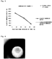
- a cross-section of the resulting tube perpendicular to the extrusion direction of the tube was mirror-polished until its surface roughness (Ra) became 0.05 um or less. Then, a determination coefficient was calculated by the aforementioned [Equation 1] using an elastic modulus ratio (%) obtained by measuring, on a straight line passing through the aforementioned regions (A), (B) and (C), the elastic moduli at any three points in each region, provided that the wall thickness of the tube at the cross-section was 100%, the elastic modulus ratio (%) being the ratio of the average value of the elastic moduli in each region and the average value of the elastic moduli in all the regions. The results are shown in Fig. 1 , and an optical microscope image of this cross-section is shown in Fig. 4 . Moreover, the peelability, transparency, diameter expansion rate, heat shrinkage rate, and peel strength of the measurement tube are shown in Table 1.
- a measurement tube was obtained in the same manner as in Example 1, except that heat shrinkage was not performed. Then, its determination coefficient was calculated. The results are shown in Fig. 2 . Moreover, the peelability, transparency, diameter expansion rate, and peel strength of the measurement tube are shown in Table 1.
- a measurement tube was obtained in the same manner as in Example 1, except that the difference between the cooling rate of the inner peripheral surface of the tube and the cooling rate of the outer peripheral surface of the tube was not reduced. Then, its determination coefficient was calculated. The results are shown in Fig. 3 .
- the heat shrink tubes of Examples 1 and 2 according to the present invention are easily peelable rectilinearly by hand, are both excellent in peelability, and have a high thermal (heat) shrinkage rate. Thus, they excel in work efficiency.
- the heat shrink tube of Comparative Example 1 has a determination coefficient close to 1.00, and its elastic modulus changes gradiently. Thus, it can be peeled manually, but is not easily peelable rectilinearly, and can be found to be inferior in peelability to Example 1.
- the heat shrink tube of Comparative Example 1 if given the same diameter expansion rate as that of Examples 1 and 2, cannot have its diameter expanded uniformly, because its elastic modulus in the region (B) is low. As a result, its shrinkage behavior during heat shrinkage is unstable. Although its heat shrinkage rate is nearly equal to that of Example 1, therefore, the tube of Comparative Example 1 cannot become a uniformly heat-shrunk tube comparable to Example 1.
- the heat shrink tube according to the present invention is found to be a heat shrink tube, which ensures a sufficient heat shrinkage rate, while possessing excellent diameter expansion strength and peelability, thus excels in both of peelability and heat shrinkage rate, and is also excellent in transparency, as compared with the conventional technologies.
- the heat shrink tube of the present invention is excellent in both of the characteristics, peelability and heat shrinkage rate, and also excels in transparency. Thus, it is useful in foods, medicine, pharmaceutics, chemistry, analytical instruments, and any other technical field.
Landscapes
- Engineering & Computer Science (AREA)
- Mechanical Engineering (AREA)
- General Engineering & Computer Science (AREA)
- Physics & Mathematics (AREA)
- Thermal Sciences (AREA)
- Manufacturing & Machinery (AREA)
- Shaping By String And By Release Of Stress In Plastics And The Like (AREA)
- Extrusion Moulding Of Plastics Or The Like (AREA)
- Manufacture Of Macromolecular Shaped Articles (AREA)
- Laminated Bodies (AREA)
Description
- This invention relates to a heat shrink tube comprising a fluororesin, excelling in peelability, and having a high thermal (heat) shrinkage rate and high transparency.
- Fluororesins are superior to other plastics, for example, in chemical stability, heat resistance, and mold release characteristics. Thus, heat shrink tubes made of fluororesins are used as protective and insulating heat shrink tubes in various fields including foods, medicine, pharmaceutics, chemistry, and analytical instruments.
- Among uses as general heat shrink tubes for protective and insulating purposes are uses involving processing of products in which the heat shrink tube is once shrink-coated, if required, and then only the heat shrink tube is peeled off.
- They include, for example, uses in which electric wires, tubes, etc. having a multilayer structure including a protective layer for a blade or the like, or having a heteromorphic structure, are shrink-coated with the heat shrink tube, and the interior members are molded or heat-welded, whereafter the heat shrink tube is removed.
- In addition to the excellent properties characteristic of fluororesins, the excellent property of the tube being easily peeled and strippable by hand, namely, peelability, is required of such uses.
-
Patent Document 1 describes a peelable tube comprising a mixture of a plurality of thermoplastic fluororesins containing different types of fluororesins. -
Patent Document 2 and Patent Document 3 show heat shrink tubes having peelability. These documents describe that fluororesins used therein are characterized by fulfilling the change amount of loss energy as specially defined; comprising a mixture of a plurality of fluororesins of different types; and containing a fluororesin accounting for a main proportion in the mixture (i.e., a main fluororesin), the main fluororesin being a polymer composed of at least three types of monomers, the polymer being a copolymer containing at least tetrafluoroethylene (TFE) and hexafluoropropylene (HFP) as its constituent monomers. - The heat shrink tubes of
Patent Documents 2 and 3, however, tend to be excellent in peelability, but are decreased in shrinkage rate, as the amounts added of the fluororesins other than the main fluororesin increase. Depending on the uses they are put to, therefore, the amount of their heat shrinkage is insufficient, and they fail to play the roles of heat shrink tubes, so that further improvements are required of them. - The present inventors have also found that the heat shrink tubes described in
Patent Documents 1 to 3 show a tendency toward better peelability with increases in the amounts of the other fluororesins added, but pose the problem of aggravated transparency such that they become cloudy, making it difficult to confirm the state of the underlying material through the heat-shrunk tube. - Patent Document 4 describes an extrusion molding apparatus, and more particularly a resin molding apparatus for molding a resin tube.
- Patent Document 5 describes a heat-shrinkable fluororesin tube which is molded by one-step operation in melt extrusion molding.
- Patent Document 6 describes an apparatus for continuously producing a heat-shrinkable cross-linked plastic tube suitable for use in covering terminal joints in pipelines and cables and shielding tubes and rods for anti-corrosion and heat insulation purposes.
-
Patent Document 1: Japanese Patent No. 4968823 Patent Document 2: Japanese Patent No. 5518268 Patent Document 3: JP-A-2014-129883 Patent Document 4: JP-A-2008-238664 Patent Document 5: JP-A-2010-125634 Patent Document 6: DE 37 87 329 T2 - A challenge for the present invention is to provide a heat shrink tube having the peelability of the publicly known heat shrink tubes and, in addition, improved in heat shrinkage rate, and excellent in transparency as well.
- The present invention provides a peelable heat shrink tube composed of a fluororesin characterized in that a determination coefficient calculated from the following [Equation 1] using an elastic modulus ratio (%) is more than 0.00, but 0.90 or less, the elastic modulus ratio (%) being obtained by measuring, on a straight line passing through regions (A), (B) and (C) below, the elastic moduli of at least three points freely selected from each region, provided that the wall thickness of the tube at a cross-section perpendicular to the extrusion direction of the tube is 100%, the elastic modulus ratio (%) being the ratio of the average value of the elastic moduli in each region and the average value of the elastic moduli in all the regions,
- (A) Region of less than 30% from the interior of the tube
- (B) Region of 30% or more, but less than 70%, from the interior of the tube
- (C) Region of 70% or more from the interior of the tube

- X: Proportion of the position of each point, where the elastic modulus was measured, from the interior of the tube
- Y: Elastic modulus ratio in each region
- Covariance: Average of the product of deviations of X and Y
- The heat shrink tube having a peel strength of 10N or less is a preferred aspect of the present invention.
- It is a preferred aspect of the present invention that the fluororesin is a copolymer melting at a temperature equal to or higher than a melting point to show fluidity, and is a copolymer of an unsaturated fluorinated hydrocarbon, an unsaturated fluorinated chlorinated hydrocarbon, or an ether group-containing unsaturated fluorinated hydrocarbon, or is at least one copolymer selected from copolymers of these unsaturated fluorinated hydrocarbons and ethylene.
- It is also a preferred aspect of the present invention that the fluororesin is a copolymer of tetrafluoroethylene and at least one monomer selected from hexafluoropropylene, fluoroalkoxytrifluoroethylene, chlorotrifluoroethylene, vinylidene fluoride and vinyl fluoride, or is at least one copolymer selected from copolymers of these monomers and ethylene.
- It is also a preferred aspect of the present invention that the fluororesin is at least one copolymer selected from tetrafluoroethylene-hexafluoropropylene copolymer (FEP), tetrafluoroethylene-perfluoroalkyl vinyl ether copolymer (PFA), tetrafluoroethylene-ethylene copolymer (ETFE), tetrafluoroethylene-hexafluoropropylene-vinylidene fluoride copolymer (THV), and polyvinylidene fluoride-polyvinylidene difluoride (PVDF).
- The present invention also provides a heat shrink tube forming method, comprising subjecting a fluororesin to melt extrusion to form a heat shrink tube, wherein the melt extrusion is performed using a melt extruder equipped with a cooling rate reducing means for reducing the difference between the cooling rate of the inner peripheral surface of the tube being melt-extruded and the cooling rate of the outer peripheral surface of the tube.
- It is a preferred aspect of the present invention that the cooling rate reducing means is provided with a mechanism for introducing at least one substance, selected from temperature controlled air, water, and a nitrogen gas, into the tube being melt-extruded by the melt extruder, so that at least one of temperature controlled air, water, and a nitrogen gas is introduced into the tube during melt extrusion.
- The heat shrink tube, and the method for producing it, according to the present invention, can be expected to show the following excellent effects:
The peel strength of the tube in the longitudinal direction is low. Thus, the tube need not be provided with a notch. Alternatively, the tube can be easily peeled by hand, with a notch measuring several millimeters or so as a starting point. Moreover, portions different in elastic modulus are present in the thickness direction of the tube. Thus, the tube is better in strength during diameter expansion than conventional tubes, so that rupture, cracking, burst or the like does not occur. As a result, a sufficient heat shrinkage rate can be ensured, with peelability stable over a continuous length being maintained. Consequently, a heat shrink tube excellent in both of peelability and heat shrinkage rate is obtained. - In addition, the heat shrinkage rate is 40% or more. Thus, clamping by the heat shrink tube is sufficiently ensured, a high work efficiency is obtained, and the tube can be put to any type of use.
-
- [
Fig. 1 ] is a view for finding a determination coefficient from the relation between the position (%) from the interior of a heat shrink tube, obtained in Example 1, and the elastic modulus ratio (%). - [
Fig. 2 ] is a view for finding a determination coefficient from the relation between the position (%) from the interior of a heat shrink tube, obtained in Example 2, and the elastic modulus ratio (%). - [
Fig. 3 ] is a view for finding a determination coefficient from the relation between the position (%) from the interior of a tube, obtained in Comparative Example 1, and the elastic modulus ratio (%). - [
Fig. 4 ] is an optical microscope image of a cross-section of the heat shrink tube of Example 1. - The peelable heat shrink tube of the present invention is obtained by melt-extruding a fluororesin. Its important feature is that a determination coefficient calculated from the aforementioned [Equation 1] using elastic moduli is more than 0.00, but 0.90 or less, the elastic moduli of optional points on a straight line connecting the optional points in the aforementioned regions (A), (B) and (C), provided that the wall thickness of the tube at a cross-section in the extrusion direction of the peelable heat shrink tube composed of the fluororesin is 100%, the straight line intersecting the regions (A), (B) and (C) perpendicularly at the optional points.
- The determination coefficient of more than 0.00, but 0.90 or less, means that there are clear differences in hardness between the regions (A), (C) and the region (B) owing to differences in the cooling rate of the resin. That is, since harder portions are present, the strength of the heat shrink tube during its diameter expansion is improved. Thus, a greater expansion in diameter can be achieved, and a greater shrinkage rate can be obtained.
- Moreover, the heat shrink tube of the present invention has a starting point for peeling, because it has portions clearly different in hardness. Thus, the tube without a notch, or having only a notch measuring several millimeters or so, can be peeled over a long distance by a smaller force.
- Generally, the amount of deformation of a cross-section of a tube when peeled is small at a site with a high elastic modulus (hard site), and is large at a site with a low elastic modulus (soft site). In a tube having sites with high and low elastic moduli present alternately, therefore, the amount of deformation is different at the points where the elastic modulus changes, presenting a starting point for breakage. There, cracking is apt to occur, resulting in easy peeling. That is, as the difference in elastic modulus at the point of change in elastic modulus increases, stable peelability is maintained over a long length, and an improvement in peelability is achieved.
- In a highly continuous tube, on the other hand, a cross-section of the tube gives a uniform or gradiently changed elastic modulus. In such a tube, the starting point for breakage occurs minimally. Thus, cracking occurs with difficulty, making it difficult to peel the tube stably over a long length.
- The above peelability at the point of change in elastic modulus can be expressed using an elastic modulus obtained by nanoindentation measurement.
- Concretely, peelability can be determined using a determination coefficient R2 according to [Equation 1] which is calculated using an elastic modulus ratio (%) obtained by measuring, on a straight line passing through the aforementioned regions (A), (B) and (C), the elastic moduli of at least three points freely selected from each region, provided that the wall thickness of the tube at a cross-section perpendicular to the extrusion direction of the tube is 100%, the elastic modulus ratio (%) being the ratio of the average value of the elastic moduli in each region and the average value of the elastic moduli in all the regions. The determination coefficient R2 represents the degree of correlation between the two parameters, i.e., the position (%) from the interior of the tube, and the ratio of the elastic modulus at each position. A determination coefficient R2 in excess of 0.90 means that the elastic moduli in the regions (A), (B) and (C) change linearly. This is not preferred, because there is no starting point for breakage, and the tube is difficult to peel.
- The heat shrink tube of the present invention preferably has a peel strength of 10N or less. With a peel strength of 10N or less, the tube can be easily peeled by hand, with a notch of the order of several millimeters as a starting point. The method of measuring the peel strength will be described later by Examples.
- More preferably, the peel strength is 5N or less. The tube with a peel strength of 5N or less can be peeled by hand, without the use of a notch as a starting point. In this case, the work efficiency of an operation for removing the heat shrink tube is improved.
- Examples of the fluororesin constituting the heat shrink tube of the present invention are copolymers melting at a temperature of a melting point or above to show fluidity, or compositions containing these copolymers. They include heat-fusible fluororesins, such as copolymers of unsaturated fluorinated hydrocarbons, unsaturated fluorinated chlorinated hydrocarbons, and ether group-containing unsaturated fluorinated hydrocarbons, etc., or copolymers of these unsaturated fluorinated hydrocarbons and ethylene.
- Their concrete examples include copolymers of tetrafluoroethylene and at least one monomer selected from hexafluoropropylene (hereinafter called HFP), fluoroalkoxytrifluoroethylene (preferably, perfluoroalkyl vinyl ether (hereinafter called PAVE)), chlorotrifluoroethylene, vinylidene fluoride, and vinyl fluoride; or copolymers of these monomers with ethylene.
- More concrete examples include tetrafluoroethylene-hexafluoropropylene copolymer (hereinafter, FEP), tetrafluoroethylene-perfluoroalkyl vinyl ether copolymer (hereinafter, PFA), tetrafluoroethylene-ethylene copolymer (hereinafter, ETFE), tetrafluoroethylene-hexafluoropropylene-vinylidene fluoride copolymer (hereinafter, THV), and polyvinylidene fluoride-polyvinylidene difluoride (hereinafter, PVDF).
- Preferred examples of the heat-fusible fluororesin, from the viewpoint of transparency, include FEP composed of two monomers (TFE and HFP). Other examples are mixtures of FEP with different melting points, and mixtures of FEP and heat-fusible fluororesins different from FEP.
- The heat-fusible fluororesins may be used alone, or may be mixtures of two or more of them. Also available are mixtures of at least two of the same type of copolymer different in the type of comonomer, comonomer content, molecular weight (weight average molecular weight or number average molecular weight), molecular weight distribution, melting point, melt flow rate (MFR), or the like, or different in mechanical properties. Their examples include mixtures of PFAs or FEPs. Such heat-fusible fluororesins can be produced by a publicly known method such as solution polymerization, emulsion polymerization, or suspension polymerization.
- The melt flow rate (MFR) of the heat-fusible fluororesin is preferably 1 to 100 g/10 min, more preferably 1 to 80 g/10 min, and further preferably 1 to 50 g/10 min. The MFR is measured at a temperature of 372°C under a load of 5 kg in accordance with ASTM D1238-95.
- The melting point of the heat-fusible fluororesin is not limited, as long as it is within a range where a tube can be formed. However, it is 150°C or higher, preferably in the range of 150 to 340°C.
- The fluororesin for use in the present invention may be a mixture of a heat-fusible fluororesin and a polymer of tetrafluoroethylene (PTFE) having no melt formability. If a heat-fusible fluororesin and PTFE are used as the fluororesin of the present invention, the melting point of the heat-fusible fluororesin is lower than the melting point of PTFE and, for the purpose of preventing compatibilization, is preferably different greatly from the melting point of PTFE.
- An example of the PTFE is a polymer of tetrafluoroethylene (TFE) alone, called a homopolymer of tetrafluoroethylene (PTFE), or a copolymer of tetrafluoroethylene containing 1% or less of a comonomer (i.e., modified PTFE). The melting point of the PTFE immediately after polymerization is 336 to 343°C, depending on the method of polymerization.
- The polymerization method for the PTFE can be a publicly known method such as solution polymerization, emulsion polymerization, or suspension polymerization. The resulting PTFE is preferably a fine powder with an average particle size of 300 to 600 um obtained by coagulating and drying polymeric primary particles obtained by emulsion polymerization.
- The content of the PTFE is 0.05 to 3.0 wt% based on the total weight of the heat-fusible fluororesin and the PTFE. If the PTFE content is in the range of 0.05 to 3.0 wt%, rupture, cracking, or burst does not occur during diameter expansion. The resulting tube is excellent in peelability, can be peeled easily by hand, and has a heat shrinkage rate of 40% or more and high work efficiency. The PTFE content is more preferably 0.2 to 1.0 wt%, because the resulting tube is excellent in peelability, and has a heat shrinkage rate of 40% or more, preferably 50% or more, demonstrating high work efficiency; that is, the tube is excellent in both of peelability and heat shrinkage.
- The method of mixing the at least two fluororesins, in preparation for forming them into a tubular shape, can be selected appropriately from the publicly known methods. Its examples will be shown below.
- The examples of the mixing method include a method of premixing dispersions of the at least two fluororesins for coaggregation; a method of premixing the at least wo fluororesins each in powdery form; and a method of further melt-mixing a fluororesin mixture, which has been obtained by premixing, to obtain a material in the form of pellets.
- The method of premixing the at least two fluororesins may be a publicly known method such as dry mixing or wet mixing. For example, the premixing can be performed using a publicly known dispersing or mixing machine such as a planetary mixer, a high speed impeller stirring machine, a rotary drum mixer, a screw mixer, a belt conveyor mixer, a ball mill, a pebble mill, a sand mill, a roll mill, an attritor, a bead mill, or a compounding extruder. A device capable of uniform dispersion is more preferred.
- The forms of the fluororesins for use in mixing are not limited. However, a dispersion of fine particles having a particle size of 0.05 to 1 µm, a powdery material measuring several micrometers to several tens of micrometers, granules of a powdery material measuring several hundred micrometers, or pellets can be named in consideration of work efficiency.
- The form of the mixture of the at least two fluororesins is, for example, a powdery material, granules of a powdery material, particles, flakes, or pellets. The average particle size of the resulting composition is 0.1 um or more, and is preferably in such a range as not to impair handleability.
- Usable as a method for obtaining the pellet-shaped material is a publicly known method, for example, comprising melt-extruding the composition by means of a single screw or twin-screw extruder to form a strand (string-shaped material), then cooling the strand, and cutting it into predetermined lengths to form pellets.
- Cutting into the predetermined lengths can be performed using a publicly known method such as strand cutting, hot cutting, or underwater cutting. The average particle size of the pellet-shaped material is 0.1 mm or more, and is preferably in such a range as not to impair handleability.
- The mixing method is not limited to those mentioned above, and a preferred method for obtaining more stable peelability over a continuous length is used.
- Next, an example of the method for melt-extruding the heat shrink tube of the present invention will be shown.
- The powdery mixture composed of at least one of the fluororesins or the pellet-shaped fluororesin mixture, prepared in advance, is melt-extruded into a tubular form. On this occasion, the melt extrusion is performed so as to fulfill the aforementioned determination coefficient.
- The melt forming (melt extrusion) refers to a forming method using a publicly known melt-forming apparatus. With this method, the material is fluidized in a molten state, whereby the melt can be converted into a formed product having sufficient strength and durability suitable for a predetermined purpose, such as a film, fibers, or a tube.
- In order for the determination coefficient calculated from the [Equation 1] to satisfy a value exceeding 0.00, but equal to or less than 0.90, among the aforementioned regions, (A) Region of less than 30% from the interior of the tube, (B) Region of 30% or more, but less than 70%, from the interior of the tube, and (C) Region of 70% or more from the interior of the tube, in the tube after melt extrusion, it is necessary to render the states of the region (A) and the region (C) nearly homogeneous, and render the state of the region (B) different in nature from those of the regions (A) and (C).
- To render the states of the region (A) and the region (C) nearly homogeneous, it is preferred to make the cooling conditions for the inner peripheral surface of the tube and the cooling conditions for the outer peripheral surface of the tube approximate to each other, when cooling the tube after melt extrusion. Normally, however, the cooling rate of the outer peripheral surface of the tube exposed to the outside air is faster than that of the inner peripheral surface of the tube presenting a closed space. In the tube after melt extrusion, therefore, the region (A) and the region (C) tend to be in heterogeneous states.
- With the present invention, in order to bring the states of the region (A) and the region (C) into practical homogeneity, it is preferred to use a cooling rate reducing means, which reduces the difference between the cooling rate of the inner peripheral surface and the cooling rate of the outer peripheral surface, during the melt extrusion of the tube.
- An example of the cooling rate reducing means is to introduce into the tube at least one of a temperature-controlled gas, for example, air, or an inert gas such as a nitrogen gas, and a liquid such as water, during melt extrusion. The use of the cooling rate reducing means during melt extrusion reduces the difference between the cooling conditions for the inner peripheral surface of the tube and the cooling conditions for the outer peripheral surface of the tube, thereby making the states of the region (A) and the region (C) nearly homogeneous in the tube after melt extrusion.
- The region (B), which is not directly exposed to the outside air temperature, is cooled more mildly than the regions (A), (C). Thus, its state is different in nature from the states of the regions (A), (C), with the result that the determination coefficient can be controlled to the predetermined range.
- As the cooling rate reducing means, other means than mentioned above may be adopted, if they contribute to the reduction of the difference in the cooling conditions for the region (A) and the region (C).
- For example, a method which comprises contacting the inner peripheral surface of the tube with a water-cooled cylindrical mold immediately after melt extrusion, thereby promoting the cooling of the inner peripheral surface of the tube, can be employed favorably.
- Moreover, if the outside air temperature is unstable, or is so high or low as to exert an adverse influence on the control of the determination coefficient, a measure for controlling the cooling rate of the outer peripheral surface of the tube, for example, by allowing the tube after melt extrusion to pass through a constant temperature bath, may also be used.
- The formed tube is heated and internally pressurized for diameter expansion, whereby it is turned into the heat shrink tube according to the present invention.
- A diameter expansion rate E is represented by the following [Equation 2]:

- L0: inner diameter of melt-extruded tube
- L: inner diameter of tube after diameter expansion
- The value of the diameter expansion rate E is not particularly limited, but correlates with the heat shrinkage rate, and an increase in the diameter expansion rate contributes to an increase in the work efficiency. If the increase is too great, however, rupture, cracking, or burst tends to occur during diameter expansion. Thus, a diameter expansion rate of 50 to 210% can be said to be a preferred range.
- However, the present invention has the region (B) which is higher in elastic modulus (harder) than the regions (A), (C). Hence, there is room for a greater diameter expansion rate and, if the strength of the fluororesin is taken into consideration, a diameter expansion rate of up to 210% or so can be achieved. Thus, the heat shrink tube of the present invention can gain a greater shrinkage rate.
- The heat shrinkage rate S is represented by the following [Equation 3]. The heat shrinkage rate S is preferably 40% or more, more preferably 50% or higher.

- P:
- inner diameter of tube after diameter expansion
- Q:
- inner diameter of tube after shrinkage
- As the heat shrinkage rate S increases, sufficient clamping by the heat shrink tube is obtained. Thus, excellent workability results, so that the tube can be put to every use. As the tube is shrunk at a higher temperature, the shrinkage rate becomes greater. To obtain a greater shrinkage rate, therefore, a method of shrinking the tube at a high temperature in a short time is also available. In this case, the shrinking temperature needs to be determined in consideration of the heat resistance of the material to be coated.
- The heat shrink tube of the present invention is characterized in that it retains a high thermal (heat) shrinkage rate, namely, a high work efficiency, and excels in contradictory properties, i.e., peelability.
- The melt extrusion method for the heat shrink tube of the present invention provides a drawdown ratio (DDR), as calculated from the following [Equation 4], of 10 to 500, preferably 20 to 300, more preferably 20 to 200.

- DD:
- inner diameter of die
- DT:
- outer diameter of mandrel
- Do:
- outer diameter of tube
- Dr:
- inner diameter of tube
- As the drawdown ratio increases, the resulting tube is better in peelability.
- The heat shrink tube of the present invention is excellent in both of peelability and heat shrinkage rate, and also excels in transparency. Thus, it is useful in foods, medicine, pharmaceutics, chemistry, analytical instruments, and any other technical field. The tube is particularly useful for uses in which electric wires, tubes, etc. having a multilayer structure including a protective layer for a blade or the like, or having a heteromorphic structure, are shrink-coated with the heat shrink tube, and interior members are molded or heat-welded, whereafter the heat shrink tube is removed.
- The present invention will now be described in more detail by way of concrete examples, but is not limited at all by these examples.
- The measuring methods are as described below.
- Using a measuring device (TI-950 Tribo Indenter, produced by Hysitron, Inc.) with an indenter of the Berkovich type under the following measurement conditions, room temperature as a measuring temperature, a maximum indentation force of 1,000 µN, an indentation speed of 200 µN/sec, a full load application time of 1.0 second, and an unloading speed of 200 µN/sec, static nanoindentation measurements were performed to obtain an elastic modulus. The points of measurements were separated by a distance equal to or more than 3 times the diameter of a dent.
- A 50 mm notch was provided near the center of the diameter at one end of a measurement sample measuring 150 mm, and bifurcated notched parts were held by chucks (fixing jigs) of a tensile tester.
- The notched parts of the measurement samples were peeled by 70 mm at a tension speed of 200 mm/min, and maximum strength under these conditions was measured. The weighted average value of the measurements (n=5) was used as peel strength.
- Peel strength was measured by the above-mentioned method, and peelability was evaluated on the following criteria:
- ⊚: Peelable by hand rectilinearly with ease.
- ○: Peelable by hand, but over a rectilinearly shorter distance than for ⊚ above.
- Measured in accordance with ASTM D1746 using a commercially available transparency measuring instrument.
- FEP (Teflon (registered trademark) FEP100-J, produced by Chemours-Mitsui Fluoroproducts Co., Ltd., MFR 7 g/10 min, melting point 260°C) comprising two monomers (TFE and HFP) was used as a heat-fusible fluororesin. A PTFE powder (melting point 336°C) lacking a heat history of the melting point thereof or higher after polymerization and having a specific gravity of 2.20 was mixed in an amount of 0.4 wt% with the heat-fusible resin. The resulting mixture was formed into pellets at a molding temperature of 300°C (a temperature lower than the melting point of PTFE). The pellets were melt-extruded (DDR=100) in the form of a tube at a forming temperature of 320°C (a temperature lower than the melting point of PTFE) by means of a melt extruder. The resulting tube was 0.35 mm in inner diameter and 1.00 mm in outer diameter. The forming temperature represents the temperature of the molten resin within the melt extruder.
- The melt extruder was equipped with a mechanism for introducing temperature-controlled air into the tube being melt-extruded. During melt extrusion, air controlled to the outside air temperature ± 3°C (20±3°C) was introduced into the tube to reduce the difference between the cooling rate of the inner peripheral surface of the tube and the cooling rate of the outer peripheral surface of the tube.
- Compressed air was poured into the resulting tube by an expansion means to expand the tube maximally to such a degree as not to cause breakage. Then, the size of the tube was measured to calculate the rate of diameter expansion. Then, the tube was heated for 10 min at 260°C for thermal shrinkage, whereby a tube for measurement was obtained.
- A cross-section of the resulting tube perpendicular to the extrusion direction of the tube was mirror-polished until its surface roughness (Ra) became 0.05 um or less. Then, a determination coefficient was calculated by the aforementioned [Equation 1] using an elastic modulus ratio (%) obtained by measuring, on a straight line passing through the aforementioned regions (A), (B) and (C), the elastic moduli at any three points in each region, provided that the wall thickness of the tube at the cross-section was 100%, the elastic modulus ratio (%) being the ratio of the average value of the elastic moduli in each region and the average value of the elastic moduli in all the regions. The results are shown in
Fig. 1 , and an optical microscope image of this cross-section is shown inFig. 4 . Moreover, the peelability, transparency, diameter expansion rate, heat shrinkage rate, and peel strength of the measurement tube are shown in Table 1. - A measurement tube was obtained in the same manner as in Example 1, except that heat shrinkage was not performed. Then, its determination coefficient was calculated. The results are shown in
Fig. 2 . Moreover, the peelability, transparency, diameter expansion rate, and peel strength of the measurement tube are shown in Table 1. - A measurement tube was obtained in the same manner as in Example 1, except that the difference between the cooling rate of the inner peripheral surface of the tube and the cooling rate of the outer peripheral surface of the tube was not reduced. Then, its determination coefficient was calculated. The results are shown in
Fig. 3 . - Moreover, the peelability, transparency, diameter expansion rate, heat shrinkage rate, and peel strength of the measurement tube are shown in Table 1.
[Table 1] PTFE content [wt%] Peelability Determination coefficient Transparency [%] Diameter Expansion rate [%] Example 1 0.4 ⊚ 0.3237 ≥80 208 2 0.4 ⊚ 0.0853 ≥80 208 Comparative Example 1 0.4 ○ 0.9854 ≥80 208 [Table 1] (Cont'd) Heat shrinkage rate [%] Peel strength [N] Example 1 59 4.5 2 - 4.1 Comparative Example 1 57 4.7 - The heat shrink tubes of Examples 1 and 2 according to the present invention are easily peelable rectilinearly by hand, are both excellent in peelability, and have a high thermal (heat) shrinkage rate. Thus, they excel in work efficiency.
- The heat shrink tube of Comparative Example 1, on the other hand, has a determination coefficient close to 1.00, and its elastic modulus changes gradiently. Thus, it can be peeled manually, but is not easily peelable rectilinearly, and can be found to be inferior in peelability to Example 1.
- In addition, the heat shrink tube of Comparative Example 1, if given the same diameter expansion rate as that of Examples 1 and 2, cannot have its diameter expanded uniformly, because its elastic modulus in the region (B) is low. As a result, its shrinkage behavior during heat shrinkage is unstable. Although its heat shrinkage rate is nearly equal to that of Example 1, therefore, the tube of Comparative Example 1 cannot become a uniformly heat-shrunk tube comparable to Example 1.
- As noted above, the heat shrink tube according to the present invention is found to be a heat shrink tube, which ensures a sufficient heat shrinkage rate, while possessing excellent diameter expansion strength and peelability, thus excels in both of peelability and heat shrinkage rate, and is also excellent in transparency, as compared with the conventional technologies.
- The heat shrink tube of the present invention is excellent in both of the characteristics, peelability and heat shrinkage rate, and also excels in transparency. Thus, it is useful in foods, medicine, pharmaceutics, chemistry, analytical instruments, and any other technical field.
Claims (8)
- A peelable heat shrink tube composed of a fluororesin,
characterised in that a determination coefficient calculated from [Equation 1] below using an elastic modulus ratio (%) is more than 0.00, but 0.90 or less, the elastic modulus ratio (%) being obtained by measuring, on a straight line passing through regions (A), (B) and (C) below, elastic moduli of at least three points freely selected from each region, provided that a wall thickness of the tube at a cross-section perpendicular to an extrusion direction of the tube is 100%, the elastic modulus ratio (%) being a ratio of an average value of the elastic moduli in each region and an average value of the elastic moduli in all the regions,(A) Region of less than 30% from an interior of the tube(B) Region of 30% or more, but less than 70%, from the interior of the tube(C) Region of 70% or more from the interior of the tubewhere X, Y and covariance represent the following: X: Proportion of a position of each point, where the elastic modulus was measured, from the interior of the tubeY: Elastic modulus ratio in each regionCovariance: Average of a product of deviations of X and Y
 - The peelable heat shrink tube according to claim 1, which has a peel strength of 10N or less.
- The peelable heat shrink tube according to claim 1 or 2, wherein
the fluororesin is a copolymer melting at a temperature equal to or higher than a melting point to show fluidity, and is a copolymer of an unsaturated fluorinated hydrocarbon, an unsaturated fluorinated chlorinated hydrocarbon, or an ether group-containing unsaturated fluorinated hydrocarbon, or is at least one copolymer selected from copolymers of these unsaturated fluorinated hydrocarbons and ethylene. - The peelable heat shrink tube according to any one of claims 1 to 3, wherein
the fluororesin is a copolymer of tetrafluoroethylene and at least one monomer selected from hexafluoropropylene, fluoroalkoxytrifluoroethylene, chlorotrifluoroethylene, vinylidene fluoride and vinyl fluoride, or is at least one copolymer selected from copolymers of these monomers and ethylene. - The peelable heat shrink tube according to any one of claims 1 to 4, wherein
the fluororesin is at least one copolymer selected from tetrafluoroethylene-hexafluoropropylene copolymer (FEP), tetrafluoroethylene-perfluoroalkyl vinyl ether copolymer (PFA), tetrafluoroethylene-ethylene copolymer (ETFE), tetrafluoroethylene-hexafluoropropylene-vinylidene fluoride copolymer (THV), and polyvinylidene fluoride-polyvinylidene difluoride (PVDF). - A heat shrink tube forming method, comprising subjecting a fluororesin to melt extrusion to form a heat shrink tube, wherein
the melt extrusion is performed using a melt extruder , the method being characterised in that said melt extruder is equipped with a cooling rate reducing means for reducing a difference between a cooling rate of an inner peripheral surface of the tube being melt-extruded and a cooling rate of an outer peripheral surface of the tube. - The heat shrink tube forming method according to claim 6, wherein
the cooling rate reducing means is provided with a mechanism for introducing at least one substance, selected from a temperature controlled gas, and a liquid, into the tube being melt-extruded by the melt extruder, so that at least one of the temperature controlled gas and the liquid is introduced into the tube during the melt extrusion. - The heat shrink tube forming method according to claim 6 or 7, whereinthe gas is at least one gas selected from air and a nitrogen gas, andthe liquid is water.
Applications Claiming Priority (2)
| Application Number | Priority Date | Filing Date | Title |
|---|---|---|---|
| JP2019158783 | 2019-08-30 | ||
| PCT/JP2020/032161 WO2021039837A1 (en) | 2019-08-30 | 2020-08-26 | Heat-shrinkable tube and method for forming same |
Publications (3)
| Publication Number | Publication Date |
|---|---|
| EP4023416A1 EP4023416A1 (en) | 2022-07-06 |
| EP4023416A4 EP4023416A4 (en) | 2022-11-30 |
| EP4023416B1 true EP4023416B1 (en) | 2024-11-13 |
Family
ID=74685034
Family Applications (1)
| Application Number | Title | Priority Date | Filing Date |
|---|---|---|---|
| EP20859022.4A Active EP4023416B1 (en) | 2019-08-30 | 2020-08-26 | Heat-shrinkable tube and method for forming same |
Country Status (5)
| Country | Link |
|---|---|
| US (1) | US12313191B2 (en) |
| EP (1) | EP4023416B1 (en) |
| JP (1) | JP6957782B2 (en) |
| CN (1) | CN114364721B (en) |
| WO (1) | WO2021039837A1 (en) |
Families Citing this family (1)
| Publication number | Priority date | Publication date | Assignee | Title |
|---|---|---|---|---|
| CN117511093A (en) * | 2023-11-10 | 2024-02-06 | 浙江脉通智造科技(集团)有限公司 | Heat shrinkable tube and preparation method thereof |
Family Cites Families (29)
| Publication number | Priority date | Publication date | Assignee | Title |
|---|---|---|---|---|
| GB1280172A (en) * | 1969-11-05 | 1972-07-05 | Pennsylvania Fluorocarbon Comp | Heat shrinkable fluorocarbon tubing |
| JPS5518268B2 (en) | 1973-04-13 | 1980-05-17 | ||
| US4510300A (en) * | 1982-04-08 | 1985-04-09 | E. I. Du Pont De Nemours And Company | Perfluorocarbon copolymer films |
| JPH0637060B2 (en) * | 1989-07-12 | 1994-05-18 | 日本ピラー工業株式会社 | Tube made of tetrafluoroethylene copolymer resin and method for producing the same |
| US7597775B2 (en) * | 2001-10-30 | 2009-10-06 | Boston Scientific Scimed, Inc. | Green fluoropolymer tube and endovascular prosthesis formed using same |
| JP4533115B2 (en) * | 2004-12-03 | 2010-09-01 | 三井・デュポンフロロケミカル株式会社 | Fluororesin molding method and fluororesin molding |
| WO2007032425A1 (en) * | 2005-09-16 | 2007-03-22 | Air Water Mach Inc. | Apparatus for producing resin tube, method for producing resin tube and resin tube |
| JP4993188B2 (en) * | 2006-03-29 | 2012-08-08 | 国立大学法人東北大学 | Resin piping |
| JP2007287876A (en) * | 2006-04-14 | 2007-11-01 | Tohoku Univ | Chemical or pure water supply apparatus, substrate processing system, substrate processing apparatus or substrate processing method |
| JP4968823B2 (en) | 2006-07-14 | 2012-07-04 | 株式会社潤工社 | Tearable tube made of fluororesin |
| US20080199646A1 (en) * | 2007-02-15 | 2008-08-21 | Medtronic Vascular, Inc. | Inline Particle Deposition Extrusion |
| US20080248226A1 (en) * | 2007-03-07 | 2008-10-09 | Saint-Gobain Performance Plastics Corporation | Multi-layer tubes |
| JP5334082B2 (en) | 2007-03-28 | 2013-11-06 | 国立大学法人東北大学 | Resin molding equipment |
| CN101678590A (en) * | 2007-05-10 | 2010-03-24 | 郡是株式会社 | Fluororesin tube and process for producing the same |
| JP2010125634A (en) | 2008-11-26 | 2010-06-10 | Suzuka Fuji Xerox Co Ltd | Method for producing heat-shrinkable fluororesin tube |
| WO2011099229A1 (en) * | 2010-02-10 | 2011-08-18 | 住友電工ファインポリマー株式会社 | Heat shrinkable tube, and production method and production device thereof |
| JP5545639B2 (en) * | 2010-04-30 | 2014-07-09 | 三井・デュポンフロロケミカル株式会社 | Fluoropolymer molded product and method for producing the same |
| SG11201401004XA (en) * | 2011-11-21 | 2014-09-26 | Junkosha Inc | Heat-shrinkable tube having tearability |
| US9370908B1 (en) * | 2012-05-18 | 2016-06-21 | Fluoron Inc. | Heat-shrink tubing process apparatus and method of making heat-shrink tubing |
| AU2015269211B2 (en) * | 2014-06-06 | 2019-12-12 | Zeus Company Inc. | Peelable heat-shrinking tubing |
| CN105216276A (en) | 2014-06-23 | 2016-01-06 | 天津春阳机械设备制造有限公司 | The air cooled chiller of thermoplastic pipes extruder |
| JP5839310B1 (en) | 2015-02-01 | 2016-01-06 | 株式会社潤工社 | Heat shrinkable tube with tearability |
| US10661497B2 (en) * | 2015-06-16 | 2020-05-26 | Nissei Electric Co., Ltd. | Heat shrink tube and method for producing the same |
| EP3135313B1 (en) | 2015-08-24 | 2020-12-02 | Junkosha Inc. | Heat-shrinkable tube having tearability |
| JP6990501B2 (en) * | 2015-08-24 | 2022-02-03 | 株式会社潤工社 | Heat-shrinkable tube with tearability |
| US10898616B1 (en) * | 2017-07-11 | 2021-01-26 | Teleflex Medical Incorporated | Peelable heat-shrink tubing |
| JP2019130880A (en) * | 2017-09-26 | 2019-08-08 | 株式会社潤工社 | Polytetrafluoroethylene tube |
| CN208468991U (en) | 2018-04-27 | 2019-02-05 | 山东东宏管业股份有限公司 | A large-diameter thick-walled pipe forming and internal air cooling device |
| JP7251550B2 (en) * | 2018-08-24 | 2023-04-04 | Agc株式会社 | Film, film manufacturing method, laminate and packaging material |
-
2020
- 2020-08-26 CN CN202080060932.9A patent/CN114364721B/en active Active
- 2020-08-26 JP JP2021515051A patent/JP6957782B2/en active Active
- 2020-08-26 WO PCT/JP2020/032161 patent/WO2021039837A1/en not_active Ceased
- 2020-08-26 US US17/638,299 patent/US12313191B2/en active Active
- 2020-08-26 EP EP20859022.4A patent/EP4023416B1/en active Active
Also Published As
| Publication number | Publication date |
|---|---|
| JPWO2021039837A1 (en) | 2021-09-27 |
| EP4023416A1 (en) | 2022-07-06 |
| CN114364721A (en) | 2022-04-15 |
| CN114364721B (en) | 2024-07-09 |
| JP6957782B2 (en) | 2021-11-02 |
| WO2021039837A1 (en) | 2021-03-04 |
| EP4023416A4 (en) | 2022-11-30 |
| US20220349500A1 (en) | 2022-11-03 |
| US12313191B2 (en) | 2025-05-27 |
Similar Documents
| Publication | Publication Date | Title |
|---|---|---|
| EP3311982B1 (en) | Heat-shrinkable tube and method for producing same | |
| US8231974B2 (en) | Fluoropolymer molding method and molded article | |
| EP2749802B1 (en) | Thermally shrinkable tube having tearing properties | |
| JP4406099B2 (en) | Formulation of fluorine plastics and polyether ketone ketone | |
| CN105840920B (en) | With lancinating heat-shrink tube | |
| EP3135313B1 (en) | Heat-shrinkable tube having tearability | |
| JPS58174407A (en) | Fluorine-containing copolymer having improved extrudability | |
| BR112016004218B1 (en) | composite fluoropolymer combination, process for forming said combination and article comprising the same | |
| US7435466B2 (en) | Polytetrafluoroethylene-based-resin tube and production method thereof | |
| JP2004035885A (en) | Blend of fluoropolymer | |
| US12313191B2 (en) | Heat shrink tube and method for forming same | |
| WO2024143463A1 (en) | Tube for semiconductor manufacturing device | |
| JP5356048B2 (en) | Thermoplastic halogenated polymer composition, process for its preparation and use thereof | |
| EP3919259B1 (en) | Heat-shrinkable tube having tearability | |
| JP7833802B2 (en) | Tear-resistant heat shrink tubing | |
| JPH05262892A (en) | Molded fluororesin product |
Legal Events
| Date | Code | Title | Description |
|---|---|---|---|
| STAA | Information on the status of an ep patent application or granted ep patent |
Free format text: STATUS: THE INTERNATIONAL PUBLICATION HAS BEEN MADE |
|
| PUAI | Public reference made under article 153(3) epc to a published international application that has entered the european phase |
Free format text: ORIGINAL CODE: 0009012 |
|
| STAA | Information on the status of an ep patent application or granted ep patent |
Free format text: STATUS: REQUEST FOR EXAMINATION WAS MADE |
|
| 17P | Request for examination filed |
Effective date: 20220221 |
|
| AK | Designated contracting states |
Kind code of ref document: A1 Designated state(s): AL AT BE BG CH CY CZ DE DK EE ES FI FR GB GR HR HU IE IS IT LI LT LU LV MC MK MT NL NO PL PT RO RS SE SI SK SM TR |
|
| A4 | Supplementary search report drawn up and despatched |
Effective date: 20221031 |
|
| RIC1 | Information provided on ipc code assigned before grant |
Ipc: B29C 48/89 20190101ALI20221025BHEP Ipc: B29C 48/885 20190101ALI20221025BHEP Ipc: B29C 48/32 20190101ALI20221025BHEP Ipc: B29C 48/09 20190101ALI20221025BHEP Ipc: C08J 5/00 20060101ALI20221025BHEP Ipc: B29C 61/02 20060101AFI20221025BHEP |
|
| DAV | Request for validation of the european patent (deleted) | ||
| DAX | Request for extension of the european patent (deleted) | ||
| GRAP | Despatch of communication of intention to grant a patent |
Free format text: ORIGINAL CODE: EPIDOSNIGR1 |
|
| STAA | Information on the status of an ep patent application or granted ep patent |
Free format text: STATUS: GRANT OF PATENT IS INTENDED |
|
| INTG | Intention to grant announced |
Effective date: 20240610 |
|
| RAP3 | Party data changed (applicant data changed or rights of an application transferred) |
Owner name: CHEMOURS-MITSUI FLUOROPRODUCTS CO., LTD. Owner name: NISSEI ELECTRIC CO., LTD. |
|
| GRAS | Grant fee paid |
Free format text: ORIGINAL CODE: EPIDOSNIGR3 |
|
| GRAA | (expected) grant |
Free format text: ORIGINAL CODE: 0009210 |
|
| STAA | Information on the status of an ep patent application or granted ep patent |
Free format text: STATUS: THE PATENT HAS BEEN GRANTED |
|
| GRAT | Correction requested after decision to grant or after decision to maintain patent in amended form |
Free format text: ORIGINAL CODE: EPIDOSNCDEC |
|
| RIN1 | Information on inventor provided before grant (corrected) |
Inventor name: SUZUKI, KOTA Inventor name: MIYAMOTO,KEI Inventor name: KIKUCHI, HIDEKI Inventor name: YABE, HIROMASA Inventor name: NODA, MINEYUKI |
|
| RIN1 | Information on inventor provided before grant (corrected) |
Inventor name: SUZUKI, KOTA Inventor name: MIYAMOTO,KEI Inventor name: KIKUCHI, HIDEKI Inventor name: YABE, HIROMASA Inventor name: NODA, MINEYUKI |
|
| AK | Designated contracting states |
Kind code of ref document: B1 Designated state(s): AL AT BE BG CH CY CZ DE DK EE ES FI FR GB GR HR HU IE IS IT LI LT LU LV MC MK MT NL NO PL PT RO RS SE SI SK SM TR |
|
| REG | Reference to a national code |
Ref country code: GB Ref legal event code: FG4D |
|
| REG | Reference to a national code |
Ref country code: CH Ref legal event code: EP |
|
| REG | Reference to a national code |
Ref country code: DE Ref legal event code: R096 Ref document number: 602020041457 Country of ref document: DE |
|
| RAP4 | Party data changed (patent owner data changed or rights of a patent transferred) |
Owner name: CHEMOURS-MITSUI FLUOROPRODUCTS CO., LTD. Owner name: NISSEI ELECTRIC CO., LTD. |
|
| REG | Reference to a national code |
Ref country code: IE Ref legal event code: FG4D |
|
| REG | Reference to a national code |
Ref country code: LT Ref legal event code: MG9D |
|
| REG | Reference to a national code |
Ref country code: NL Ref legal event code: MP Effective date: 20241113 |
|
| PG25 | Lapsed in a contracting state [announced via postgrant information from national office to epo] |
Ref country code: HR Free format text: LAPSE BECAUSE OF FAILURE TO SUBMIT A TRANSLATION OF THE DESCRIPTION OR TO PAY THE FEE WITHIN THE PRESCRIBED TIME-LIMIT Effective date: 20241113 Ref country code: IS Free format text: LAPSE BECAUSE OF FAILURE TO SUBMIT A TRANSLATION OF THE DESCRIPTION OR TO PAY THE FEE WITHIN THE PRESCRIBED TIME-LIMIT Effective date: 20250313 Ref country code: PT Free format text: LAPSE BECAUSE OF FAILURE TO SUBMIT A TRANSLATION OF THE DESCRIPTION OR TO PAY THE FEE WITHIN THE PRESCRIBED TIME-LIMIT Effective date: 20250313 |
|
| PG25 | Lapsed in a contracting state [announced via postgrant information from national office to epo] |
Ref country code: FI Free format text: LAPSE BECAUSE OF FAILURE TO SUBMIT A TRANSLATION OF THE DESCRIPTION OR TO PAY THE FEE WITHIN THE PRESCRIBED TIME-LIMIT Effective date: 20241113 Ref country code: NL Free format text: LAPSE BECAUSE OF FAILURE TO SUBMIT A TRANSLATION OF THE DESCRIPTION OR TO PAY THE FEE WITHIN THE PRESCRIBED TIME-LIMIT Effective date: 20241113 |
|
| REG | Reference to a national code |
Ref country code: AT Ref legal event code: MK05 Ref document number: 1741370 Country of ref document: AT Kind code of ref document: T Effective date: 20241113 |
|
| PG25 | Lapsed in a contracting state [announced via postgrant information from national office to epo] |
Ref country code: BG Free format text: LAPSE BECAUSE OF FAILURE TO SUBMIT A TRANSLATION OF THE DESCRIPTION OR TO PAY THE FEE WITHIN THE PRESCRIBED TIME-LIMIT Effective date: 20241113 |
|
| PG25 | Lapsed in a contracting state [announced via postgrant information from national office to epo] |
Ref country code: ES Free format text: LAPSE BECAUSE OF FAILURE TO SUBMIT A TRANSLATION OF THE DESCRIPTION OR TO PAY THE FEE WITHIN THE PRESCRIBED TIME-LIMIT Effective date: 20241113 |
|
| PG25 | Lapsed in a contracting state [announced via postgrant information from national office to epo] |
Ref country code: NO Free format text: LAPSE BECAUSE OF FAILURE TO SUBMIT A TRANSLATION OF THE DESCRIPTION OR TO PAY THE FEE WITHIN THE PRESCRIBED TIME-LIMIT Effective date: 20250213 |
|
| PG25 | Lapsed in a contracting state [announced via postgrant information from national office to epo] |
Ref country code: LV Free format text: LAPSE BECAUSE OF FAILURE TO SUBMIT A TRANSLATION OF THE DESCRIPTION OR TO PAY THE FEE WITHIN THE PRESCRIBED TIME-LIMIT Effective date: 20241113 Ref country code: GR Free format text: LAPSE BECAUSE OF FAILURE TO SUBMIT A TRANSLATION OF THE DESCRIPTION OR TO PAY THE FEE WITHIN THE PRESCRIBED TIME-LIMIT Effective date: 20250214 Ref country code: AT Free format text: LAPSE BECAUSE OF FAILURE TO SUBMIT A TRANSLATION OF THE DESCRIPTION OR TO PAY THE FEE WITHIN THE PRESCRIBED TIME-LIMIT Effective date: 20241113 |
|
| PG25 | Lapsed in a contracting state [announced via postgrant information from national office to epo] |
Ref country code: PL Free format text: LAPSE BECAUSE OF FAILURE TO SUBMIT A TRANSLATION OF THE DESCRIPTION OR TO PAY THE FEE WITHIN THE PRESCRIBED TIME-LIMIT Effective date: 20241113 |
|
| PG25 | Lapsed in a contracting state [announced via postgrant information from national office to epo] |
Ref country code: RS Free format text: LAPSE BECAUSE OF FAILURE TO SUBMIT A TRANSLATION OF THE DESCRIPTION OR TO PAY THE FEE WITHIN THE PRESCRIBED TIME-LIMIT Effective date: 20250213 |
|
| PG25 | Lapsed in a contracting state [announced via postgrant information from national office to epo] |
Ref country code: SM Free format text: LAPSE BECAUSE OF FAILURE TO SUBMIT A TRANSLATION OF THE DESCRIPTION OR TO PAY THE FEE WITHIN THE PRESCRIBED TIME-LIMIT Effective date: 20241113 |
|
| PG25 | Lapsed in a contracting state [announced via postgrant information from national office to epo] |
Ref country code: DK Free format text: LAPSE BECAUSE OF FAILURE TO SUBMIT A TRANSLATION OF THE DESCRIPTION OR TO PAY THE FEE WITHIN THE PRESCRIBED TIME-LIMIT Effective date: 20241113 |
|
| PG25 | Lapsed in a contracting state [announced via postgrant information from national office to epo] |
Ref country code: EE Free format text: LAPSE BECAUSE OF FAILURE TO SUBMIT A TRANSLATION OF THE DESCRIPTION OR TO PAY THE FEE WITHIN THE PRESCRIBED TIME-LIMIT Effective date: 20241113 |
|
| PG25 | Lapsed in a contracting state [announced via postgrant information from national office to epo] |
Ref country code: RO Free format text: LAPSE BECAUSE OF FAILURE TO SUBMIT A TRANSLATION OF THE DESCRIPTION OR TO PAY THE FEE WITHIN THE PRESCRIBED TIME-LIMIT Effective date: 20241113 |
|
| PG25 | Lapsed in a contracting state [announced via postgrant information from national office to epo] |
Ref country code: SK Free format text: LAPSE BECAUSE OF FAILURE TO SUBMIT A TRANSLATION OF THE DESCRIPTION OR TO PAY THE FEE WITHIN THE PRESCRIBED TIME-LIMIT Effective date: 20241113 |
|
| PG25 | Lapsed in a contracting state [announced via postgrant information from national office to epo] |
Ref country code: CZ Free format text: LAPSE BECAUSE OF FAILURE TO SUBMIT A TRANSLATION OF THE DESCRIPTION OR TO PAY THE FEE WITHIN THE PRESCRIBED TIME-LIMIT Effective date: 20241113 |
|
| PG25 | Lapsed in a contracting state [announced via postgrant information from national office to epo] |
Ref country code: IT Free format text: LAPSE BECAUSE OF FAILURE TO SUBMIT A TRANSLATION OF THE DESCRIPTION OR TO PAY THE FEE WITHIN THE PRESCRIBED TIME-LIMIT Effective date: 20241113 |
|
| PGFP | Annual fee paid to national office [announced via postgrant information from national office to epo] |
Ref country code: IE Payment date: 20250624 Year of fee payment: 6 |
|
| REG | Reference to a national code |
Ref country code: DE Ref legal event code: R097 Ref document number: 602020041457 Country of ref document: DE |
|
| PG25 | Lapsed in a contracting state [announced via postgrant information from national office to epo] |
Ref country code: SE Free format text: LAPSE BECAUSE OF FAILURE TO SUBMIT A TRANSLATION OF THE DESCRIPTION OR TO PAY THE FEE WITHIN THE PRESCRIBED TIME-LIMIT Effective date: 20241113 |
|
| PLBE | No opposition filed within time limit |
Free format text: ORIGINAL CODE: 0009261 |
|
| STAA | Information on the status of an ep patent application or granted ep patent |
Free format text: STATUS: NO OPPOSITION FILED WITHIN TIME LIMIT |
|
| PGFP | Annual fee paid to national office [announced via postgrant information from national office to epo] |
Ref country code: DE Payment date: 20250702 Year of fee payment: 6 |
|
| PGFP | Annual fee paid to national office [announced via postgrant information from national office to epo] |
Ref country code: GB Payment date: 20250703 Year of fee payment: 6 |
|
| PGFP | Annual fee paid to national office [announced via postgrant information from national office to epo] |
Ref country code: FR Payment date: 20250703 Year of fee payment: 6 |
|
| 26N | No opposition filed |
Effective date: 20250814 |
|
| REG | Reference to a national code |
Ref country code: CH Ref legal event code: H13 Free format text: ST27 STATUS EVENT CODE: U-0-0-H10-H13 (AS PROVIDED BY THE NATIONAL OFFICE) Effective date: 20260324 |
|
| PG25 | Lapsed in a contracting state [announced via postgrant information from national office to epo] |
Ref country code: MC Free format text: LAPSE BECAUSE OF FAILURE TO SUBMIT A TRANSLATION OF THE DESCRIPTION OR TO PAY THE FEE WITHIN THE PRESCRIBED TIME-LIMIT Effective date: 20241113 |
|
| PG25 | Lapsed in a contracting state [announced via postgrant information from national office to epo] |
Ref country code: LU Free format text: LAPSE BECAUSE OF NON-PAYMENT OF DUE FEES Effective date: 20250826 |
|
| PG25 | Lapsed in a contracting state [announced via postgrant information from national office to epo] |
Ref country code: CH Free format text: LAPSE BECAUSE OF NON-PAYMENT OF DUE FEES Effective date: 20250831 |