EP4023391A1 - Method for working a workpiece made of wood and working plant for implementing the method - Google Patents
Method for working a workpiece made of wood and working plant for implementing the method Download PDFInfo
- Publication number
- EP4023391A1 EP4023391A1 EP21213813.5A EP21213813A EP4023391A1 EP 4023391 A1 EP4023391 A1 EP 4023391A1 EP 21213813 A EP21213813 A EP 21213813A EP 4023391 A1 EP4023391 A1 EP 4023391A1
- Authority
- EP
- European Patent Office
- Prior art keywords
- workpiece
- decoration
- working
- worked
- unit
- Prior art date
- Legal status (The legal status is an assumption and is not a legal conclusion. Google has not performed a legal analysis and makes no representation as to the accuracy of the status listed.)
- Granted
Links
Images
Classifications
-
- B—PERFORMING OPERATIONS; TRANSPORTING
- B29—WORKING OF PLASTICS; WORKING OF SUBSTANCES IN A PLASTIC STATE IN GENERAL
- B29C—SHAPING OR JOINING OF PLASTICS; SHAPING OF MATERIAL IN A PLASTIC STATE, NOT OTHERWISE PROVIDED FOR; AFTER-TREATMENT OF THE SHAPED PRODUCTS, e.g. REPAIRING
- B29C63/00—Lining or sheathing, i.e. applying preformed layers or sheathings of plastics; Apparatus therefor
- B29C63/02—Lining or sheathing, i.e. applying preformed layers or sheathings of plastics; Apparatus therefor using sheet or web-like material
-
- B—PERFORMING OPERATIONS; TRANSPORTING
- B24—GRINDING; POLISHING
- B24B—MACHINES, DEVICES, OR PROCESSES FOR GRINDING OR POLISHING; DRESSING OR CONDITIONING OF ABRADING SURFACES; FEEDING OF GRINDING, POLISHING, OR LAPPING AGENTS
- B24B7/00—Machines or devices designed for grinding plane surfaces on work, including polishing plane glass surfaces; Accessories therefor
- B24B7/06—Machines or devices designed for grinding plane surfaces on work, including polishing plane glass surfaces; Accessories therefor involving conveyor belts, a sequence of travelling work-tables or the like
-
- B—PERFORMING OPERATIONS; TRANSPORTING
- B24—GRINDING; POLISHING
- B24B—MACHINES, DEVICES, OR PROCESSES FOR GRINDING OR POLISHING; DRESSING OR CONDITIONING OF ABRADING SURFACES; FEEDING OF GRINDING, POLISHING, OR LAPPING AGENTS
- B24B7/00—Machines or devices designed for grinding plane surfaces on work, including polishing plane glass surfaces; Accessories therefor
- B24B7/20—Machines or devices designed for grinding plane surfaces on work, including polishing plane glass surfaces; Accessories therefor characterised by a special design with respect to properties of the material of non-metallic articles to be ground
- B24B7/28—Machines or devices designed for grinding plane surfaces on work, including polishing plane glass surfaces; Accessories therefor characterised by a special design with respect to properties of the material of non-metallic articles to be ground for grinding wood
-
- B—PERFORMING OPERATIONS; TRANSPORTING
- B24—GRINDING; POLISHING
- B24B—MACHINES, DEVICES, OR PROCESSES FOR GRINDING OR POLISHING; DRESSING OR CONDITIONING OF ABRADING SURFACES; FEEDING OF GRINDING, POLISHING, OR LAPPING AGENTS
- B24B7/00—Machines or devices designed for grinding plane surfaces on work, including polishing plane glass surfaces; Accessories therefor
- B24B7/20—Machines or devices designed for grinding plane surfaces on work, including polishing plane glass surfaces; Accessories therefor characterised by a special design with respect to properties of the material of non-metallic articles to be ground
- B24B7/30—Machines or devices designed for grinding plane surfaces on work, including polishing plane glass surfaces; Accessories therefor characterised by a special design with respect to properties of the material of non-metallic articles to be ground for grinding plastics
Definitions
- the present invention relates to a method of working workpiece made of wood, in particular the decoration and lamination of pieces.
- the present invention also relates to a plant for working workpieces made of wood, which implements the method, in particular a sanding type machine, equipped with a decoration unit and a pressing unit, and a sanding unit.
- the invention relates to a method of working workpieces made of wood or other materials too, such as plastic, glass, fiberglass, metal, ceramic, and the like, in particular for the decoration by means of a laser source and the subsequent lamination, but which can be used for any decoration of a wooden workpiece.
- Each roller rotates on a workpiece by compressing it, thus allowing to impress on the surface of the workpiece the decoration on the surface of the roller itself.
- the workpiece is subsequently inserted into an autoclave device, where an ennobled layer is applied on the worked surface of the workpiece.
- the ennobled layer adheres to the worked surface of the workpiece, assuming the same conformation as the worked surface of the workpiece.
- a further disadvantage of the prior art is that the dimensions of the decorations to be carried out on the workpieces are limited by the physical sizes of the rollers or of the pre-printed cards.
- an object of the present invention to provide a method for processing wooden pieces that performs a fast and safe decoration machining for the workpiece and the subsequent lamination.
- Another object of the invention is to provide a method for working pieces by means of which it is possible to impress on the same piece, or on following pieces, different decorative elements, which can be modified quickly.
- Another object of the present invention is to provide a method that allows the entire surface of the piece to be decorated.
- a further object of the present invention is to provide a plant, which implements the method of machining wooden pieces.
- said decoration carried out in said step b is a removal of material by means of a laser source or a print by means of a print head or a painting.
- said method may comprise the following step: b1. detecting the quality of the decoration carried out in said step b., if the decoration corresponds to the predetermined decoration program, carrying out said step c.
- said method comprises the following step: a1. detecting the features of the workpiece to be worked, and/or an input data, and selecting the decoration program to carry out.
- a working plant for working a workpiece made of wood, plastic, glass, fiberglass, metal, ceramic comprising a machine capable of carrying out a decoration on a workpiece by means of a decoration unit, and comprising a pressing or laminating unit capable of pressing a layer of noble material on said decorated workpiece.
- said plant may comprise a second detecting device arranged between said machine and said pressing or laminating unit capable of detecting the quality of the decoration carried out on said workpiece.
- said plant may comprise a first detecting device arranged at the entry of said machine, capable of detecting the features of said workpiece.
- said plant may comprise a logic control unit in which decoration programs to carry out on said workpiece are stored.
- said logic control unit is capable of receiving signals corresponding to the quality of decoration detected by said detecting device and sending correspondingly said workpiece to said pressing or laminating unit.
- said logic control unit is capable of receiving signals corresponding to the features detected by said first detecting device and selecting correspondingly the decoration program to carry out on said workpiece.
- said machine (M) comprises an entry station for the entry of said workpiece to be worked and an exit station for the exit of said worked workpiece, a conveyor group for moving said workpiece to be worked, according to a forward direction, from said entry station towards said exit station; a decoration unit capable of carrying out a decoration on said workpiece, and at least one working unit, in particular a sanding unit, of said workpiece, arranged elevated with respect to said conveyor group comprising at least one working tool, in particular for sanding said workpiece.
- said machine comprises an entry station for the entry of said workpiece to be worked and an exit station for the exit of the worked workpiece, a conveyor group for moving said workpiece to be worked, according to a forward direction, from said entry station towards said exit station, and a decoration unit capable of carrying out a decoration on said workpiece.
- a machine for working a workpiece made of wood, plastic, glass, fiberglass, metal, ceramic comprising an entry station for the entry of said workpiece to be worked and an exit station for the exit of the worked workpiece, a conveyor group for moving said workpiece to be worked, according to a forward direction, from said entry station towards said exit station, a decoration unit capable of carrying out a decoration on said workpiece, and a pressing or laminating unit capable of pressing a layer of noble material on said decorated workpiece.
- said decoration unit is a laser source or a print head, or a painting unit.
- the method for working wooden workpieces object of the present invention, essentially comprises the steps of inserting a workpiece P to be worked in the plant, carrying out the decoration on the workpiece, performing the laminating of the workpiece.
- the workpiece P is essentially a panel such as furniture doors, or parquet strips, made of non-noble material that is subsequently ennobled by means of the method in at issue.
- the machining that is performed is the sanding or brushing or a working by using a laser source or printing or painting on the workpiece P.
- the lamination which consists in superimposing an ennobled layer on the worked surface of the workpiece, in order to give mechanical stability and impermeability to the workpiece.
- the working plant I object of the present invention, which implements the method described above, in a first embodiment, essentially comprises a machine M for working the workpiece P, a pressing or laminating unit L of the workpiece P, and a logic control unit U, operatively connected to said machine M and to said pressing or laminating unit L, for the operation of the plant I.
- Said machine M substantially comprises an entry station 1, where the workpieces P to be worked are inserted according to a first axis or forward direction X, an exit station 2 from which worked workpieces P exit, according to the same direction X, a conveyor group 3, for transporting the workpieces P to be worked according to said forward direction X, from said entry station 1, towards said exit station 2, at least one working unit 4 for carrying out a working, in particular sanding, on said workpieces P to be worked, and a decoration unit 5 for decorating said workpieces P.
- Said conveyor group 3 comprises a conveyor belt 31, on which the workpiece P to be worked is placed and transported from said entry station 1 towards said exit station 2, according to the forward direction X, and a first 32 and a second 33 shaft, which rotates said conveyor belt 31.
- Said at least one working unit 4 is arranged above said conveyor group 3 and it extends according to a third axis or development direction Z, orthogonal to said forward direction X.
- Said at least one working unit 4 comprises at least one sanding tool 41, provided with an abrasive surface, facing the underlying conveyor belt 31, for contacting with the upper surface of the workpiece P, arranged above the same conveyor belt 31.
- Said sanding tool 41 can also be an abrasive roller, or a rotary disk, such as a sanding pad, or a brush, or a tool with cutting elements.
- Said working unit 4 carries out the sanding of the workpiece P according to a second axis, or working direction Y, which is orthogonal to the plane identified by said forward direction X and the development direction Z.
- Said working unit 4 can also comprise several sanding tools 41.
- Said decoration unit 5 is arranged in said working unit 4, between said at least one working tool 41, and said exit station 2, for decorating said workpiece P.
- said decoration unit 5 is used to decorate said workpiece P, following the main sanding workings carried out by the previous working groups.
- Said decoration unit 5 can be a laser source or a printing head or a painting unit.
- Said decoration unit 5 also carries out the working on said workpiece P by moving along said working direction Y, while the workpiece P moves forward along said forward direction X.
- said decoration unit 5 is a laser source, the workings are carried out on the workpiece P according to predetermined decoration programs, in order to decorate the workpiece with veins, stripes, geometric effects, and the like, on the whole surface of the workpiece or on part of it, by removing material.
- said decoration unit 5 is a print head, the workings are carried out on the workpiece P according to predetermined decoration programs, in order to decorate the workpiece with prints, images, and the like, on the whole surface of the workpiece or on part of it.
- said decoration unit 5 is a painting unit, the workings are carried out on the workpiece P according to predetermined decoration programs, in order to paint the whole surface of the workpiece or part of it.
- Said first detecting device 6 is arranged in said entry station 1, elevated above said conveyor belt 31 and is operatively connected to said logic control unit U.
- Said working center C comprises a first detecting device 6.
- Said first detecting device 6 is capable of detecting one or more features of the workpiece P while entering into said plant I, such as for example the sizes of said workpiece P and/or the material of said workpiece P and/or the position of said workpiece P on said conveyor belt 31, in particular the rotation of the workpiece P on the plane XY, with respect to the forward direction X, and/or an input data, and to send corresponding signals to said logic control unit U.
- Said first detecting device 6 is a camera or an optical sensor.
- Said machine M comprises a second detecting device 7.
- Said second detecting device 7 is arranged in said exit station 2, elevated above said conveyor belt 31, and it is operatively connected to said logic control unit U.
- Said second detecting device 7 is capable of controlling the working carried out on said workpiece P, in particular of detecting the depth of the marking on the workpiece P, the shade of the workpiece P after the working, the resolution, and correspondence with respect to the input working.
- Said pressing or laminating unit L comprises a base B, on which the workpiece P to be laminated is placed, a pressing member S, which is moved, with respect to said base, by means of a plurality of hydraulic cylinders L1, L2, L3, and L4, in order to apply, by pressing, a layer of noble material N on said workpiece P.
- Said logic control unit U comprises processing programs to be carried out on said workpiece P by means of said working unit 4, and it is operatively connected to said working unit 4.
- Said logic control unit U also comprises the decoration programs to be carried out on said workpiece P by means of said decoration unit 5, and it is operatively connected with said decoration unit 5.
- Said logic control unit U is able to receive the signals coming from said second detecting device 7 and to consequently activate the laminating unit L.
- object of the present invention which implements the method described above, differs from the first embodiment I described above, just for the fact that it does not comprise said working unit 4. Therefore, the workpieces P are only decorated by said decoration unit 5, as described above.
- the plant comprises a single machine comprising an entry station 1, for the entry of said workpiece P to be worked, an exit station 2, for the exit of the worked workpiece P, a conveyor group 3 for transporting said workpiece P to be worked, according to a forward direction X, from said entry station 1 towards said exit station 2, and further comprising a decoration unit 5, able to carry out a decoration on said workpiece P, and a pressing or laminating unit L, capable of pressing a layer of noble material N on said decorated workpiece P.
- Said workpiece P is transported in said machine M according to said forward direction X.
- Said first detecting device 6 detects the features of the workpiece P and sends corresponding signals to said logic control unit U, which correspondingly selects the working and the decoration program to be carried out on said workpiece P.
- Said workpiece P is firstly worked by said working unit 4, according to the working program selected by said logic control unit U.
- said workpiece P is decorated by said decoration unit 5, along said working direction Y, according to the decoration program selected by said logic control unit U, i.e. working by means of a laser, or by a printing head or by a painting unit, while the workpiece P advances along said forward direction X.
- said conveyor belt 31 transports said decorated workpiece P to said exit station 2.
- Said second detecting device 7 detects the quality of the decoration of said workpiece P, and whether it corresponds to the resulting decoration from the selected decoration program, then said workpiece P is sent to said pressing or laminating unit L.
- Said pressing or laminating unit L applies a layer of noble material N on said workpiece P.
- said plurality of hydraulic cylinders L1, L2, L3, and L4 moves said pressing member S towards said workpiece P for pressing and adhering said layer of noble material N on said workpiece P.
- the operation of the plant I' is similar to the one just described, and differs only for the fact that the workpiece P is not worked first, but is only decorated.
- the method object of the present invention allows carrying out different decorations on said workpiece P quickly and on the whole surface of the workpiece, or part of it, according to the physical features of the workpiece.
Landscapes
- Engineering & Computer Science (AREA)
- Manufacturing & Machinery (AREA)
- Laser Beam Processing (AREA)
Abstract
Description
- The present invention relates to a method of working workpiece made of wood, in particular the decoration and lamination of pieces.
- The present invention also relates to a plant for working workpieces made of wood, which implements the method, in particular a sanding type machine, equipped with a decoration unit and a pressing unit, and a sanding unit.
- More in detail, the invention relates to a method of working workpieces made of wood or other materials too, such as plastic, glass, fiberglass, metal, ceramic, and the like, in particular for the decoration by means of a laser source and the subsequent lamination, but which can be used for any decoration of a wooden workpiece.
- In the following, the description will address a method for decorating a workpiece made of wood by means of a laser source, and for subsequently laminating it, but it is clear that it should not be considered limited to this specific use.
- As is well known, currently there exist methods and machines for working workpieces made of wood, in particular for decorating the workpieces with veins or geometric shapes or for impressing various kinds of decorations on the workpiece.
- These known machines are pressing machines, which carry out the working on the workpieces by pressing rollers.
- In particular, the machines equipped with rollers, on the surface of which there are veins, geometric shapes, and other kinds of decorative elements, are known.
- Each roller rotates on a workpiece by compressing it, thus allowing to impress on the surface of the workpiece the decoration on the surface of the roller itself.
- To ennoble the workpiece, the latter is subsequently inserted into an autoclave device, where an ennobled layer is applied on the worked surface of the workpiece.
- Due to the heat and the pressure of the autoclave device, the ennobled layer adheres to the worked surface of the workpiece, assuming the same conformation as the worked surface of the workpiece.
- Additionally known machines apply decorated surfaces or pre-printed cards on the workpieces by pressure.
- As is apparent, these known methods and machines provide for long working times, which are sometimes harmful to the workpieces, due to the pressure applied by the roller on the workpiece itself.
- Furthermore, to vary the working on a workpiece or on following workpieces, it is necessary to replace the roller in the machine for exerting a roller that has a surface with a different decorative element.
- A further disadvantage of the prior art is that the dimensions of the decorations to be carried out on the workpieces are limited by the physical sizes of the rollers or of the pre-printed cards.
- In the light of the above, it is, therefore, an object of the present invention to provide a method for processing wooden pieces that performs a fast and safe decoration machining for the workpiece and the subsequent lamination.
- Another object of the invention is to provide a method for working pieces by means of which it is possible to impress on the same piece, or on following pieces, different decorative elements, which can be modified quickly.
- Another object of the present invention is to provide a method that allows the entire surface of the piece to be decorated.
- A further object of the present invention is to provide a plant, which implements the method of machining wooden pieces.
- It is, therefore, a specific object of the present invention a method for working a workpiece made of wood, plastic, glass, fiberglass, metal, ceramic, comprising the following steps:
- a. providing a workpiece to be worked in a working plant, according to a forward direction;
- b. carrying out the decoration of the workpiece according to a predetermined decoration program, along a working direction, orthogonal to said forward direction, while said workpiece moves along said forward direction; and
- c. carrying out the pressing of a layer of noble material on said decorated workpiece.
- Further according to the invention, said decoration carried out in said step b. is a removal of material by means of a laser source or a print by means of a print head or a painting.
- Still according to the invention, said method may comprise the following step:
b1. detecting the quality of the decoration carried out in said step b., if the decoration corresponds to the predetermined decoration program, carrying out said step c. - Preferably according to the invention, said method comprises the following step:
a1. detecting the features of the workpiece to be worked, and/or an input data, and selecting the decoration program to carry out. - It is further object of the present invention, a working plant for working a workpiece made of wood, plastic, glass, fiberglass, metal, ceramic, comprising a machine capable of carrying out a decoration on a workpiece by means of a decoration unit, and comprising a pressing or laminating unit capable of pressing a layer of noble material on said decorated workpiece.
- Further according to the invention, said plant may comprise a second detecting device arranged between said machine and said pressing or laminating unit capable of detecting the quality of the decoration carried out on said workpiece.
- Still according to the invention, said plant may comprise a first detecting device arranged at the entry of said machine, capable of detecting the features of said workpiece.
- Preferably according to the invention, said plant may comprise a logic control unit in which decoration programs to carry out on said workpiece are stored.
- Always according to the invention, said logic control unit is capable of receiving signals corresponding to the quality of decoration detected by said detecting device and sending correspondingly said workpiece to said pressing or laminating unit.
- Further according to the invention, said logic control unit is capable of receiving signals corresponding to the features detected by said first detecting device and selecting correspondingly the decoration program to carry out on said workpiece.
- Still according to the invention, said machine (M) comprises an entry station for the entry of said workpiece to be worked and an exit station for the exit of said worked workpiece, a conveyor group for moving said workpiece to be worked, according to a forward direction, from said entry station towards said exit station; a decoration unit capable of carrying out a decoration on said workpiece, and at least one working unit, in particular a sanding unit, of said workpiece, arranged elevated with respect to said conveyor group comprising at least one working tool, in particular for sanding said workpiece.
- Preferably according to the invention, said machine comprises an entry station for the entry of said workpiece to be worked and an exit station for the exit of the worked workpiece, a conveyor group for moving said workpiece to be worked, according to a forward direction, from said entry station towards said exit station, and a decoration unit capable of carrying out a decoration on said workpiece.
- It is further object of the present invention a machine for working a workpiece made of wood, plastic, glass, fiberglass, metal, ceramic, comprising an entry station for the entry of said workpiece to be worked and an exit station for the exit of the worked workpiece, a conveyor group for moving said workpiece to be worked, according to a forward direction, from said entry station towards said exit station, a decoration unit capable of carrying out a decoration on said workpiece, and a pressing or laminating unit capable of pressing a layer of noble material on said decorated workpiece.
- Still according to the invention, said decoration unit is a laser source or a print head, or a painting unit.
- The present invention will be now described, for illustrative but not limitative purposes, according to its preferred embodiments, with particular reference to the figures of the enclosed drawings, wherein:
-
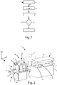
figure 1 shows a flowchart of the method for working workpieces made of wood, object of the present invention; -
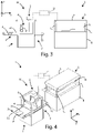
figure 2 shows a perspective side view of a first embodiment of the plant, which implements the working method, object of the present invention; -
figure 3 shows a side view of the plant offigure 2 ; -
figure 4 shows a top perspective view of the plant offigure 2 ; -
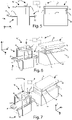
figure 5 shows a side view of a second embodiment of the plant, which implements the working method, object of the present invention; -
figure 6 shows a side perspective view of the plant offigure 5 ; and -
figure 7 shows a top perspective view of the plant offigure 5 . - In the various figures, similar parts will be indicated with the same numerical references.
- With reference to
figure 1 , the method for working wooden workpieces, object of the present invention, essentially comprises the steps of inserting a workpiece P to be worked in the plant, carrying out the decoration on the workpiece, performing the laminating of the workpiece. - The workpiece P is essentially a panel such as furniture doors, or parquet strips, made of non-noble material that is subsequently ennobled by means of the method in at issue.
- The machining that is performed is the sanding or brushing or a working by using a laser source or printing or painting on the workpiece P.
- Once the working of the workpiece is over, it is possible to perform the lamination, which consists in superimposing an ennobled layer on the worked surface of the workpiece, in order to give mechanical stability and impermeability to the workpiece.
- In the method, it is possible to provide a verification step of the quality of the working, to decide whether to laminate the workpiece or not.
- With reference to
figures 2-4 , the working plant I, object of the present invention, which implements the method described above, in a first embodiment, essentially comprises a machine M for working the workpiece P, a pressing or laminating unit L of the workpiece P, and a logic control unit U, operatively connected to said machine M and to said pressing or laminating unit L, for the operation of the plant I. - Said machine M substantially comprises an
entry station 1, where the workpieces P to be worked are inserted according to a first axis or forward direction X, anexit station 2 from which worked workpieces P exit, according to the same direction X, aconveyor group 3, for transporting the workpieces P to be worked according to said forward direction X, from saidentry station 1, towards saidexit station 2, at least one workingunit 4 for carrying out a working, in particular sanding, on said workpieces P to be worked, and adecoration unit 5 for decorating said workpieces P. - In particular, in said
entry station 1, a workpiece P is placed on saidconveyor group 3. - Said
conveyor group 3 comprises aconveyor belt 31, on which the workpiece P to be worked is placed and transported from saidentry station 1 towards saidexit station 2, according to the forward direction X, and a first 32 and a second 33 shaft, which rotates saidconveyor belt 31. - Said at least one working
unit 4 is arranged above saidconveyor group 3 and it extends according to a third axis or development direction Z, orthogonal to said forward direction X. - Said at least one working
unit 4 comprises at least onesanding tool 41, provided with an abrasive surface, facing theunderlying conveyor belt 31, for contacting with the upper surface of the workpiece P, arranged above thesame conveyor belt 31. - Said sanding
tool 41 can also be an abrasive roller, or a rotary disk, such as a sanding pad, or a brush, or a tool with cutting elements. - Said working
unit 4 carries out the sanding of the workpiece P according to a second axis, or working direction Y, which is orthogonal to the plane identified by said forward direction X and the development direction Z. - Said working
unit 4 can also compriseseveral sanding tools 41. - Said
decoration unit 5 is arranged in said workingunit 4, between said at least one workingtool 41, and saidexit station 2, for decorating said workpiece P. - In particular, said
decoration unit 5 is used to decorate said workpiece P, following the main sanding workings carried out by the previous working groups. - Said
decoration unit 5 can be a laser source or a printing head or a painting unit. - Said
decoration unit 5 also carries out the working on said workpiece P by moving along said working direction Y, while the workpiece P moves forward along said forward direction X. - If said
decoration unit 5 is a laser source, the workings are carried out on the workpiece P according to predetermined decoration programs, in order to decorate the workpiece with veins, stripes, geometric effects, and the like, on the whole surface of the workpiece or on part of it, by removing material. - If said
decoration unit 5 is a print head, the workings are carried out on the workpiece P according to predetermined decoration programs, in order to decorate the workpiece with prints, images, and the like, on the whole surface of the workpiece or on part of it. - If said
decoration unit 5 is a painting unit, the workings are carried out on the workpiece P according to predetermined decoration programs, in order to paint the whole surface of the workpiece or part of it. - Said first detecting
device 6 is arranged in saidentry station 1, elevated above saidconveyor belt 31 and is operatively connected to said logic control unit U. - Said working center C comprises a first detecting
device 6. - Said first detecting
device 6 is capable of detecting one or more features of the workpiece P while entering into said plant I, such as for example the sizes of said workpiece P and/or the material of said workpiece P and/or the position of said workpiece P on saidconveyor belt 31, in particular the rotation of the workpiece P on the plane XY, with respect to the forward direction X, and/or an input data, and to send corresponding signals to said logic control unit U. - Said first detecting
device 6 is a camera or an optical sensor. - Said machine M comprises a second detecting
device 7. - Said second detecting
device 7 is arranged in saidexit station 2, elevated above saidconveyor belt 31, and it is operatively connected to said logic control unit U. - Said second detecting
device 7 is capable of controlling the working carried out on said workpiece P, in particular of detecting the depth of the marking on the workpiece P, the shade of the workpiece P after the working, the resolution, and correspondence with respect to the input working. - Said pressing or laminating unit L comprises a base B, on which the workpiece P to be laminated is placed, a pressing member S, which is moved, with respect to said base, by means of a plurality of hydraulic cylinders L1, L2, L3, and L4, in order to apply, by pressing, a layer of noble material N on said workpiece P.
- Said logic control unit U comprises processing programs to be carried out on said workpiece P by means of said working
unit 4, and it is operatively connected to said workingunit 4. - Said logic control unit U also comprises the decoration programs to be carried out on said workpiece P by means of said
decoration unit 5, and it is operatively connected with saiddecoration unit 5. - Said logic control unit U is able to receive the signals coming from said second detecting
device 7 and to consequently activate the laminating unit L. - Referring now to
figures 5-7 , in a second embodiment of said plant I', object of the present invention, which implements the method described above, differs from the first embodiment I described above, just for the fact that it does not comprise said workingunit 4. Therefore, the workpieces P are only decorated by saiddecoration unit 5, as described above. - In a third embodiment, not shown in the figures, it is also possible that the plant comprises a single machine comprising an
entry station 1, for the entry of said workpiece P to be worked, anexit station 2, for the exit of the worked workpiece P, aconveyor group 3 for transporting said workpiece P to be worked, according to a forward direction X, from saidentry station 1 towards saidexit station 2, and further comprising adecoration unit 5, able to carry out a decoration on said workpiece P, and a pressing or laminating unit L, capable of pressing a layer of noble material N on said decorated workpiece P. - The operation of the plant I described above is as follows.
- When decorating a workpiece P is desired, the latter is inserted in said plant I, in particular on said
conveyor belt 31 in saidentry station 1. - Said workpiece P is transported in said machine M according to said forward direction X.
- Said first detecting
device 6 detects the features of the workpiece P and sends corresponding signals to said logic control unit U, which correspondingly selects the working and the decoration program to be carried out on said workpiece P. - Said workpiece P is firstly worked by said working
unit 4, according to the working program selected by said logic control unit U. - Subsequently, said workpiece P is decorated by said
decoration unit 5, along said working direction Y, according to the decoration program selected by said logic control unit U, i.e. working by means of a laser, or by a printing head or by a painting unit, while the workpiece P advances along said forward direction X. - At the end of the decoration, said
conveyor belt 31 transports said decorated workpiece P to saidexit station 2. - Said second detecting
device 7 detects the quality of the decoration of said workpiece P, and whether it corresponds to the resulting decoration from the selected decoration program, then said workpiece P is sent to said pressing or laminating unit L. - Said pressing or laminating unit L applies a layer of noble material N on said workpiece P.
- In particular, said plurality of hydraulic cylinders L1, L2, L3, and L4, moves said pressing member S towards said workpiece P for pressing and adhering said layer of noble material N on said workpiece P.
- The operation of the plant I' is similar to the one just described, and differs only for the fact that the workpiece P is not worked first, but is only decorated.
- As is evident from the present invention, the method object of the present invention allows carrying out different decorations on said workpiece P quickly and on the whole surface of the workpiece, or part of it, according to the physical features of the workpiece.
- The present invention has been described for illustrative but not limitative purposes, according to its preferred embodiments, but it is to be understood that modifications and/or changes can be introduced by those skilled in the art without departing from the relevant scope as defined in the enclosed claims.
Claims (14)
- Method for working a workpiece (P) made of wood, plastic, glass, fiberglass, metal, ceramic, comprising the following steps:a. providing a workpiece (P) to be worked in a working plant (I, I'), according to a forward direction (X);b. carrying out the decoration of the workpiece (P) according to a predetermined decoration program, along a working direction (Y), orthogonal to said forward direction (X), while said workpiece (P) moves along said forward direction (X); andc. carrying out the pressing of a layer of noble material (N) on said decorated workpiece (P).
- Method according to the preceding claim, characterized in that said decoration carried out in said step b. is a removal of material by means of a laser source, or a print by means of a print head or a painting.
- Method according to any one of the preceding claims, characterized in that it comprises the following step:
b1. detecting the quality of the decoration carried out in said step b., if the decoration corresponds to the predetermined decoration program, carrying out said step c. - Method according to any one of the preceding claims, characterized in that it comprises the following step:
a1. detecting the features of the workpiece (P) to be worked, and/or an input data, and selecting the decoration program to carry out. - Working plant (I, I') for working a workpiece (P) made of wood, plastic, glass, fiberglass, metal, ceramic, characterizedin that it comprises a machine (M, M') capable of carrying out a decoration on a workpiece (P) by means of a decoration unit (5), andin that it comprises a pressing or laminating unit (L) capable of pressing a layer of noble material (N) on said decorated workpiece (P).
- Plant (I, I') according to the preceding claim, characterized in that it comprises a second detecting device (7) arranged between said machine (M, M') and said pressing or laminating unit (L) capable of detecting the quality of the decoration carried out on said workpiece (P).
- Plant (I, I') according to any one of claims 5 or 6, characterized in that it comprises a first detecting device (6) arranged at the entry of said machine (M, M'), capable of detecting the features of said workpiece (P).
- Plant (I, I') according to any one of claims 5-7, characterized in that it comprises a logic control unit (U) in which decoration programs to carry out on said workpiece (P) are stored.
- Plant (I, I') according to the preceding claim, when dependent on claim 6, characterized in that said logic control unit (U) is capable of receiving signals corresponding to the quality of decoration detected by said detecting device (7) and sending correspondingly said workpiece to said pressing or laminating unit (L).
- Plant (I, I') according to claim 8, when dependent on claim 7, characterized in that said logic control unit (U) is capable of receiving signals corresponding to the features detected by said first detecting device (6) and selecting correspondingly the decoration program to carry out on said workpiece (P).
- Plant (I) according to any one of claims 5-10, characterized in that said machine (M) comprises:an entry station (1) for the entry of said workpiece (P) to be worked and an exit station (2) for the exit of said worked workpiece (P);a conveyor group (3) for moving said workpiece (P) to be worked, according to a forward direction (X), from said entry station (1) towards said exit station (2);a decoration unit (5) capable of carrying out a decoration on said workpiece (P); andat least one working unit (4), in particular a sanding unit, of said workpiece (P), arranged elevated with respect to said conveyor group (3) comprising at least one working tool (41), in particular for sanding said workpiece (P).
- Plant (I') according to any one of claims 5-10, characterized in that said machine (M') comprises:an entry station (1) for the entry of said workpiece (P) to be worked and an exit station (2) for the exit of the worked workpiece (P);a conveyor group (3) for moving said workpiece (P) to be worked, according to a forward direction (X), from said entry station (1) towards said exit station (2); anda decoration unit (5) capable of carrying out a decoration on said workpiece (P).
- Plant (I, I') according to any one of claims 5-12, characterized in that said decoration unit (5) is a laser source or a print head or a painting unit.
- Machine for working a workpiece (P) made of wood, plastic, glass, fiberglass, metal, ceramic, comprising:an entry station (1) for the entry of said workpiece (P) to be worked and an exit station (2) for the exit of the worked workpiece (P);a conveyor group (3) for moving said workpiece (P) to be worked, according to a forward direction (X), from said entry station (1) towards said exit station (2);characterized in that it further comprises a decoration unit (5) capable of carrying out a decoration on said workpiece (P), and a pressing or laminating unit (L) capable of pressing a layer of noble material (N) on said decorated workpiece (P).
Applications Claiming Priority (1)
| Application Number | Priority Date | Filing Date | Title |
|---|---|---|---|
| IT202000032729 | 2020-12-30 |
Publications (2)
| Publication Number | Publication Date |
|---|---|
| EP4023391A1 true EP4023391A1 (en) | 2022-07-06 |
| EP4023391B1 EP4023391B1 (en) | 2024-07-24 |
Family
ID=75252637
Family Applications (1)
| Application Number | Title | Priority Date | Filing Date |
|---|---|---|---|
| EP21213813.5A Active EP4023391B1 (en) | 2020-12-30 | 2021-12-10 | Method for working a workpiece made of wood and working plant for implementing the method |
Country Status (1)
| Country | Link |
|---|---|
| EP (1) | EP4023391B1 (en) |
Citations (3)
| Publication number | Priority date | Publication date | Assignee | Title |
|---|---|---|---|---|
| GB2263884A (en) * | 1992-02-07 | 1993-08-11 | Sagittario S R L | Method of decorating a molding made of wood or similar material by means of engraving |
| KR20110069982A (en) * | 2009-12-18 | 2011-06-24 | 김영갑 | How to make medals made of aluminum |
| CN111361342A (en) * | 2020-04-16 | 2020-07-03 | 邢台市洛宸牌匾碑刻艺术有限公司 | Method for engraving convex book body |
-
2021
- 2021-12-10 EP EP21213813.5A patent/EP4023391B1/en active Active
Patent Citations (3)
| Publication number | Priority date | Publication date | Assignee | Title |
|---|---|---|---|---|
| GB2263884A (en) * | 1992-02-07 | 1993-08-11 | Sagittario S R L | Method of decorating a molding made of wood or similar material by means of engraving |
| KR20110069982A (en) * | 2009-12-18 | 2011-06-24 | 김영갑 | How to make medals made of aluminum |
| CN111361342A (en) * | 2020-04-16 | 2020-07-03 | 邢台市洛宸牌匾碑刻艺术有限公司 | Method for engraving convex book body |
Also Published As
| Publication number | Publication date |
|---|---|
| EP4023391B1 (en) | 2024-07-24 |
Similar Documents
| Publication | Publication Date | Title |
|---|---|---|
| US4128119A (en) | Apparatus for processing workpieces in the form of short-length elongate timber waste into usable timber | |
| US5751435A (en) | Method and apparatus for aligning a cylinder in an engraver | |
| US20100196678A1 (en) | Method of manufacturing a laminate panel, an apparatus and a laminate panel | |
| US6210512B1 (en) | Embossing of laminated picture frame molding | |
| US20230038080A1 (en) | Method for printing on a workpiece and printing device | |
| PT2080630E (en) | Production line for manufacturing of flat wood-based panels with a printed upper surface | |
| CN105593029A (en) | Method for producing a hydrophobic or superhydrophobic surface topography | |
| US20020132050A1 (en) | Apparatus and methods for producing artificially distressed plank flooring | |
| US20240307915A1 (en) | Machine and method for treating a workpiece | |
| US20230330693A1 (en) | Coating apparatus and method | |
| EP4023391B1 (en) | Method for working a workpiece made of wood and working plant for implementing the method | |
| EP3254817A1 (en) | Process for the restoration or the consolidation of slabs of stone material | |
| TWI793304B (en) | Machine and method for machining an edge of a workpiece | |
| JPH06508073A (en) | Equipment with a polisher that operates transversely in the direction of workpiece progress and its application to polishing frames | |
| CN117021267B (en) | Decorative plate processing flaw treatment system and processing method thereof | |
| CN111098370A (en) | Production process of spliced ecological plate | |
| EP3302906B1 (en) | Method for producing a wood structure with a decorational pattern, a device for patterning a piece of wood and a decorational wood structure | |
| US20050090183A1 (en) | Automated processing unit for a working station | |
| KR101866856B1 (en) | MDF laminated plywood seat system in the | |
| EP1403019A2 (en) | Apparatus for making a kind of artistic decoration on ceramic tiles | |
| EP3741573B1 (en) | Machine for printing substrates and method for printing substrates using said machine | |
| EP0835850B1 (en) | Method for surface processing a glass plate and processed glass plate obtained thereby | |
| WO2008082322A1 (en) | Method for producing a shaped surface and a device for carrying out said method | |
| KR20040027275A (en) | process and apparatus for making a pattern on a surface of synthetic wood | |
| KR101849283B1 (en) | Apparatus for surface treatment of synthetic wood |
Legal Events
| Date | Code | Title | Description |
|---|---|---|---|
| PUAI | Public reference made under article 153(3) epc to a published international application that has entered the european phase |
Free format text: ORIGINAL CODE: 0009012 |
|
| STAA | Information on the status of an ep patent application or granted ep patent |
Free format text: STATUS: THE APPLICATION HAS BEEN PUBLISHED |
|
| AK | Designated contracting states |
Kind code of ref document: A1 Designated state(s): AL AT BE BG CH CY CZ DE DK EE ES FI FR GB GR HR HU IE IS IT LI LT LU LV MC MK MT NL NO PL PT RO RS SE SI SK SM TR |
|
| STAA | Information on the status of an ep patent application or granted ep patent |
Free format text: STATUS: REQUEST FOR EXAMINATION WAS MADE |
|
| 17P | Request for examination filed |
Effective date: 20221229 |
|
| RBV | Designated contracting states (corrected) |
Designated state(s): AL AT BE BG CH CY CZ DE DK EE ES FI FR GB GR HR HU IE IS IT LI LT LU LV MC MK MT NL NO PL PT RO RS SE SI SK SM TR |
|
| P01 | Opt-out of the competence of the unified patent court (upc) registered |
Effective date: 20230518 |
|
| REG | Reference to a national code |
Ref country code: DE Ref legal event code: R079 Free format text: PREVIOUS MAIN CLASS: B24B0007060000 Ipc: B29C0063020000 Ref country code: DE Ref legal event code: R079 Ref document number: 602021016091 Country of ref document: DE Free format text: PREVIOUS MAIN CLASS: B24B0007060000 Ipc: B29C0063020000 |
|
| GRAP | Despatch of communication of intention to grant a patent |
Free format text: ORIGINAL CODE: EPIDOSNIGR1 |
|
| STAA | Information on the status of an ep patent application or granted ep patent |
Free format text: STATUS: GRANT OF PATENT IS INTENDED |
|
| RIC1 | Information provided on ipc code assigned before grant |
Ipc: B24B 7/30 20060101ALN20240227BHEP Ipc: B24B 7/28 20060101ALN20240227BHEP Ipc: B24B 7/06 20060101ALN20240227BHEP Ipc: B29C 63/02 20060101AFI20240227BHEP |
|
| INTG | Intention to grant announced |
Effective date: 20240312 |
|
| GRAS | Grant fee paid |
Free format text: ORIGINAL CODE: EPIDOSNIGR3 |
|
| GRAA | (expected) grant |
Free format text: ORIGINAL CODE: 0009210 |
|
| STAA | Information on the status of an ep patent application or granted ep patent |
Free format text: STATUS: THE PATENT HAS BEEN GRANTED |
|
| AK | Designated contracting states |
Kind code of ref document: B1 Designated state(s): AL AT BE BG CH CY CZ DE DK EE ES FI FR GB GR HR HU IE IS IT LI LT LU LV MC MK MT NL NO PL PT RO RS SE SI SK SM TR |
|
| REG | Reference to a national code |
Ref country code: GB Ref legal event code: FG4D |
|
| REG | Reference to a national code |
Ref country code: CH Ref legal event code: EP |
|
| REG | Reference to a national code |
Ref country code: IE Ref legal event code: FG4D Ref country code: DE Ref legal event code: R096 Ref document number: 602021016091 Country of ref document: DE |
|
| REG | Reference to a national code |
Ref country code: LT Ref legal event code: MG9D |
|
| REG | Reference to a national code |
Ref country code: NL Ref legal event code: MP Effective date: 20240724 |
|
| PG25 | Lapsed in a contracting state [announced via postgrant information from national office to epo] |
Ref country code: PT Free format text: LAPSE BECAUSE OF FAILURE TO SUBMIT A TRANSLATION OF THE DESCRIPTION OR TO PAY THE FEE WITHIN THE PRESCRIBED TIME-LIMIT Effective date: 20241125 |
|
| REG | Reference to a national code |
Ref country code: AT Ref legal event code: MK05 Ref document number: 1705942 Country of ref document: AT Kind code of ref document: T Effective date: 20240724 |
|
| PG25 | Lapsed in a contracting state [announced via postgrant information from national office to epo] |
Ref country code: NL Free format text: LAPSE BECAUSE OF FAILURE TO SUBMIT A TRANSLATION OF THE DESCRIPTION OR TO PAY THE FEE WITHIN THE PRESCRIBED TIME-LIMIT Effective date: 20240724 |
|
| PG25 | Lapsed in a contracting state [announced via postgrant information from national office to epo] |
Ref country code: PT Free format text: LAPSE BECAUSE OF FAILURE TO SUBMIT A TRANSLATION OF THE DESCRIPTION OR TO PAY THE FEE WITHIN THE PRESCRIBED TIME-LIMIT Effective date: 20241125 Ref country code: NL Free format text: LAPSE BECAUSE OF FAILURE TO SUBMIT A TRANSLATION OF THE DESCRIPTION OR TO PAY THE FEE WITHIN THE PRESCRIBED TIME-LIMIT Effective date: 20240724 |
|
| PG25 | Lapsed in a contracting state [announced via postgrant information from national office to epo] |
Ref country code: NO Free format text: LAPSE BECAUSE OF FAILURE TO SUBMIT A TRANSLATION OF THE DESCRIPTION OR TO PAY THE FEE WITHIN THE PRESCRIBED TIME-LIMIT Effective date: 20241024 |
|
| PG25 | Lapsed in a contracting state [announced via postgrant information from national office to epo] |
Ref country code: FI Free format text: LAPSE BECAUSE OF FAILURE TO SUBMIT A TRANSLATION OF THE DESCRIPTION OR TO PAY THE FEE WITHIN THE PRESCRIBED TIME-LIMIT Effective date: 20240724 Ref country code: GR Free format text: LAPSE BECAUSE OF FAILURE TO SUBMIT A TRANSLATION OF THE DESCRIPTION OR TO PAY THE FEE WITHIN THE PRESCRIBED TIME-LIMIT Effective date: 20241025 Ref country code: PL Free format text: LAPSE BECAUSE OF FAILURE TO SUBMIT A TRANSLATION OF THE DESCRIPTION OR TO PAY THE FEE WITHIN THE PRESCRIBED TIME-LIMIT Effective date: 20240724 |
|
| PG25 | Lapsed in a contracting state [announced via postgrant information from national office to epo] |
Ref country code: BG Free format text: LAPSE BECAUSE OF FAILURE TO SUBMIT A TRANSLATION OF THE DESCRIPTION OR TO PAY THE FEE WITHIN THE PRESCRIBED TIME-LIMIT Effective date: 20240724 |
|
| PG25 | Lapsed in a contracting state [announced via postgrant information from national office to epo] |
Ref country code: LV Free format text: LAPSE BECAUSE OF FAILURE TO SUBMIT A TRANSLATION OF THE DESCRIPTION OR TO PAY THE FEE WITHIN THE PRESCRIBED TIME-LIMIT Effective date: 20240724 |
|
| PG25 | Lapsed in a contracting state [announced via postgrant information from national office to epo] |
Ref country code: IS Free format text: LAPSE BECAUSE OF FAILURE TO SUBMIT A TRANSLATION OF THE DESCRIPTION OR TO PAY THE FEE WITHIN THE PRESCRIBED TIME-LIMIT Effective date: 20241124 Ref country code: AT Free format text: LAPSE BECAUSE OF FAILURE TO SUBMIT A TRANSLATION OF THE DESCRIPTION OR TO PAY THE FEE WITHIN THE PRESCRIBED TIME-LIMIT Effective date: 20240724 |
|
| PG25 | Lapsed in a contracting state [announced via postgrant information from national office to epo] |
Ref country code: HR Free format text: LAPSE BECAUSE OF FAILURE TO SUBMIT A TRANSLATION OF THE DESCRIPTION OR TO PAY THE FEE WITHIN THE PRESCRIBED TIME-LIMIT Effective date: 20240724 |
|
| PG25 | Lapsed in a contracting state [announced via postgrant information from national office to epo] |
Ref country code: RS Free format text: LAPSE BECAUSE OF FAILURE TO SUBMIT A TRANSLATION OF THE DESCRIPTION OR TO PAY THE FEE WITHIN THE PRESCRIBED TIME-LIMIT Effective date: 20241024 Ref country code: ES Free format text: LAPSE BECAUSE OF FAILURE TO SUBMIT A TRANSLATION OF THE DESCRIPTION OR TO PAY THE FEE WITHIN THE PRESCRIBED TIME-LIMIT Effective date: 20240724 |
|
| PG25 | Lapsed in a contracting state [announced via postgrant information from national office to epo] |
Ref country code: RS Free format text: LAPSE BECAUSE OF FAILURE TO SUBMIT A TRANSLATION OF THE DESCRIPTION OR TO PAY THE FEE WITHIN THE PRESCRIBED TIME-LIMIT Effective date: 20241024 Ref country code: PL Free format text: LAPSE BECAUSE OF FAILURE TO SUBMIT A TRANSLATION OF THE DESCRIPTION OR TO PAY THE FEE WITHIN THE PRESCRIBED TIME-LIMIT Effective date: 20240724 Ref country code: NO Free format text: LAPSE BECAUSE OF FAILURE TO SUBMIT A TRANSLATION OF THE DESCRIPTION OR TO PAY THE FEE WITHIN THE PRESCRIBED TIME-LIMIT Effective date: 20241024 Ref country code: LV Free format text: LAPSE BECAUSE OF FAILURE TO SUBMIT A TRANSLATION OF THE DESCRIPTION OR TO PAY THE FEE WITHIN THE PRESCRIBED TIME-LIMIT Effective date: 20240724 Ref country code: IS Free format text: LAPSE BECAUSE OF FAILURE TO SUBMIT A TRANSLATION OF THE DESCRIPTION OR TO PAY THE FEE WITHIN THE PRESCRIBED TIME-LIMIT Effective date: 20241124 Ref country code: HR Free format text: LAPSE BECAUSE OF FAILURE TO SUBMIT A TRANSLATION OF THE DESCRIPTION OR TO PAY THE FEE WITHIN THE PRESCRIBED TIME-LIMIT Effective date: 20240724 Ref country code: GR Free format text: LAPSE BECAUSE OF FAILURE TO SUBMIT A TRANSLATION OF THE DESCRIPTION OR TO PAY THE FEE WITHIN THE PRESCRIBED TIME-LIMIT Effective date: 20241025 Ref country code: FI Free format text: LAPSE BECAUSE OF FAILURE TO SUBMIT A TRANSLATION OF THE DESCRIPTION OR TO PAY THE FEE WITHIN THE PRESCRIBED TIME-LIMIT Effective date: 20240724 Ref country code: ES Free format text: LAPSE BECAUSE OF FAILURE TO SUBMIT A TRANSLATION OF THE DESCRIPTION OR TO PAY THE FEE WITHIN THE PRESCRIBED TIME-LIMIT Effective date: 20240724 Ref country code: BG Free format text: LAPSE BECAUSE OF FAILURE TO SUBMIT A TRANSLATION OF THE DESCRIPTION OR TO PAY THE FEE WITHIN THE PRESCRIBED TIME-LIMIT Effective date: 20240724 Ref country code: AT Free format text: LAPSE BECAUSE OF FAILURE TO SUBMIT A TRANSLATION OF THE DESCRIPTION OR TO PAY THE FEE WITHIN THE PRESCRIBED TIME-LIMIT Effective date: 20240724 |
|
| PG25 | Lapsed in a contracting state [announced via postgrant information from national office to epo] |
Ref country code: SM Free format text: LAPSE BECAUSE OF FAILURE TO SUBMIT A TRANSLATION OF THE DESCRIPTION OR TO PAY THE FEE WITHIN THE PRESCRIBED TIME-LIMIT Effective date: 20240724 Ref country code: RO Free format text: LAPSE BECAUSE OF FAILURE TO SUBMIT A TRANSLATION OF THE DESCRIPTION OR TO PAY THE FEE WITHIN THE PRESCRIBED TIME-LIMIT Effective date: 20240724 Ref country code: DK Free format text: LAPSE BECAUSE OF FAILURE TO SUBMIT A TRANSLATION OF THE DESCRIPTION OR TO PAY THE FEE WITHIN THE PRESCRIBED TIME-LIMIT Effective date: 20240724 |
|
| PG25 | Lapsed in a contracting state [announced via postgrant information from national office to epo] |
Ref country code: EE Free format text: LAPSE BECAUSE OF FAILURE TO SUBMIT A TRANSLATION OF THE DESCRIPTION OR TO PAY THE FEE WITHIN THE PRESCRIBED TIME-LIMIT Effective date: 20240724 |
|
| PG25 | Lapsed in a contracting state [announced via postgrant information from national office to epo] |
Ref country code: CZ Free format text: LAPSE BECAUSE OF FAILURE TO SUBMIT A TRANSLATION OF THE DESCRIPTION OR TO PAY THE FEE WITHIN THE PRESCRIBED TIME-LIMIT Effective date: 20240724 |
|
| REG | Reference to a national code |
Ref country code: DE Ref legal event code: R097 Ref document number: 602021016091 Country of ref document: DE |
|
| PG25 | Lapsed in a contracting state [announced via postgrant information from national office to epo] |
Ref country code: SK Free format text: LAPSE BECAUSE OF FAILURE TO SUBMIT A TRANSLATION OF THE DESCRIPTION OR TO PAY THE FEE WITHIN THE PRESCRIBED TIME-LIMIT Effective date: 20240724 |
|
| PLBE | No opposition filed within time limit |
Free format text: ORIGINAL CODE: 0009261 |
|
| STAA | Information on the status of an ep patent application or granted ep patent |
Free format text: STATUS: NO OPPOSITION FILED WITHIN TIME LIMIT |
|
| 26N | No opposition filed |
Effective date: 20250425 |
|
| PG25 | Lapsed in a contracting state [announced via postgrant information from national office to epo] |
Ref country code: MC Free format text: LAPSE BECAUSE OF FAILURE TO SUBMIT A TRANSLATION OF THE DESCRIPTION OR TO PAY THE FEE WITHIN THE PRESCRIBED TIME-LIMIT Effective date: 20240724 |
|
| PG25 | Lapsed in a contracting state [announced via postgrant information from national office to epo] |
Ref country code: LU Free format text: LAPSE BECAUSE OF NON-PAYMENT OF DUE FEES Effective date: 20241210 |
|
| PG25 | Lapsed in a contracting state [announced via postgrant information from national office to epo] |
Ref country code: SE Free format text: LAPSE BECAUSE OF FAILURE TO SUBMIT A TRANSLATION OF THE DESCRIPTION OR TO PAY THE FEE WITHIN THE PRESCRIBED TIME-LIMIT Effective date: 20240724 |
|
| REG | Reference to a national code |
Ref country code: BE Ref legal event code: MM Effective date: 20241231 |
|
| PG25 | Lapsed in a contracting state [announced via postgrant information from national office to epo] |
Ref country code: BE Free format text: LAPSE BECAUSE OF NON-PAYMENT OF DUE FEES Effective date: 20241231 |
|
| PG25 | Lapsed in a contracting state [announced via postgrant information from national office to epo] |
Ref country code: FR Free format text: LAPSE BECAUSE OF NON-PAYMENT OF DUE FEES Effective date: 20241231 |
|
| PG25 | Lapsed in a contracting state [announced via postgrant information from national office to epo] |
Ref country code: IE Free format text: LAPSE BECAUSE OF NON-PAYMENT OF DUE FEES Effective date: 20241210 |
|
| REG | Reference to a national code |
Ref country code: CH Ref legal event code: U11 Free format text: ST27 STATUS EVENT CODE: U-0-0-U10-U11 (AS PROVIDED BY THE NATIONAL OFFICE) Effective date: 20260101 |
|
| PGFP | Annual fee paid to national office [announced via postgrant information from national office to epo] |
Ref country code: IT Payment date: 20251013 Year of fee payment: 5 |
|
| PGFP | Annual fee paid to national office [announced via postgrant information from national office to epo] |
Ref country code: DE Payment date: 20251222 Year of fee payment: 5 |
|
| PGFP | Annual fee paid to national office [announced via postgrant information from national office to epo] |
Ref country code: CH Payment date: 20260101 Year of fee payment: 5 |
|
| PG25 | Lapsed in a contracting state [announced via postgrant information from national office to epo] |
Ref country code: CY Free format text: LAPSE BECAUSE OF FAILURE TO SUBMIT A TRANSLATION OF THE DESCRIPTION OR TO PAY THE FEE WITHIN THE PRESCRIBED TIME-LIMIT Effective date: 20240724 |