EP4023377A1 - Chuck device - Google Patents
Chuck device Download PDFInfo
- Publication number
- EP4023377A1 EP4023377A1 EP20888897.4A EP20888897A EP4023377A1 EP 4023377 A1 EP4023377 A1 EP 4023377A1 EP 20888897 A EP20888897 A EP 20888897A EP 4023377 A1 EP4023377 A1 EP 4023377A1
- Authority
- EP
- European Patent Office
- Prior art keywords
- workpiece
- rod
- rods
- housing
- chuck device
- Prior art date
- Legal status (The legal status is an assumption and is not a legal conclusion. Google has not performed a legal analysis and makes no representation as to the accuracy of the status listed.)
- Pending
Links
- 210000000078 claw Anatomy 0.000 claims abstract description 63
- 238000003754 machining Methods 0.000 description 18
- 230000008878 coupling Effects 0.000 description 15
- 238000010168 coupling process Methods 0.000 description 15
- 238000005859 coupling reaction Methods 0.000 description 15
- 230000037431 insertion Effects 0.000 description 10
- 238000003780 insertion Methods 0.000 description 10
- 230000002093 peripheral effect Effects 0.000 description 6
- 238000007789 sealing Methods 0.000 description 4
- 230000000694 effects Effects 0.000 description 2
Images


Classifications
-
- B—PERFORMING OPERATIONS; TRANSPORTING
- B23—MACHINE TOOLS; METAL-WORKING NOT OTHERWISE PROVIDED FOR
- B23B—TURNING; BORING
- B23B31/00—Chucks; Expansion mandrels; Adaptations thereof for remote control
- B23B31/02—Chucks
- B23B31/10—Chucks characterised by the retaining or gripping devices or their immediate operating means
- B23B31/12—Chucks with simultaneously-acting jaws, whether or not also individually adjustable
- B23B31/18—Chucks with simultaneously-acting jaws, whether or not also individually adjustable pivotally movable in planes containing the axis of the chuck
-
- B—PERFORMING OPERATIONS; TRANSPORTING
- B23—MACHINE TOOLS; METAL-WORKING NOT OTHERWISE PROVIDED FOR
- B23B—TURNING; BORING
- B23B31/00—Chucks; Expansion mandrels; Adaptations thereof for remote control
- B23B31/02—Chucks
- B23B31/10—Chucks characterised by the retaining or gripping devices or their immediate operating means
- B23B31/12—Chucks with simultaneously-acting jaws, whether or not also individually adjustable
- B23B31/19—Chucks with simultaneously-acting jaws, whether or not also individually adjustable moving parallel to the axis of the chuck
-
- B—PERFORMING OPERATIONS; TRANSPORTING
- B23—MACHINE TOOLS; METAL-WORKING NOT OTHERWISE PROVIDED FOR
- B23B—TURNING; BORING
- B23B2270/00—Details of turning, boring or drilling machines, processes or tools not otherwise provided for
- B23B2270/09—Details relating to unclamping
-
- Y—GENERAL TAGGING OF NEW TECHNOLOGICAL DEVELOPMENTS; GENERAL TAGGING OF CROSS-SECTIONAL TECHNOLOGIES SPANNING OVER SEVERAL SECTIONS OF THE IPC; TECHNICAL SUBJECTS COVERED BY FORMER USPC CROSS-REFERENCE ART COLLECTIONS [XRACs] AND DIGESTS
- Y10—TECHNICAL SUBJECTS COVERED BY FORMER USPC
- Y10T—TECHNICAL SUBJECTS COVERED BY FORMER US CLASSIFICATION
- Y10T279/00—Chucks or sockets
- Y10T279/18—Pivoted jaw
Definitions
- the present invention relates to a chuck device for holding a workpiece supplied to a machine tool, and more particularly to a chuck device provided with a plurality of workpiece holding claws.
- a workpiece chuck device which comprises: a chuck main body; a reference fixing claw that is fixed to one end side of the chuck main body and is for supporting one end of the workpiece; a movable claw that is provided on one end side of the chuck main body so as to be able to be opened and closed with respect to the reference fixing claw and is for supporting one end portion of the workpiece; drive means for opening and closing the movable claw; and a stopper for supporting the other end of the workpiece (for example, in the patent literature 1).
- the side of the workpiece is clamped by the claws. Therefore, when the workpiece is a plate material, the workpiece may be deformed or buckled.
- the present invention is for solving the problem of the prior art as described above, that is, the object of the present invention is to provide a chuck device for holding a plate material workpiece supplied to a machine tool without deforming the workpiece.
- the present invention is characterized by a chuck device comprising: a plurality of rods provided with workpiece holding claws for holding a workpiece supplied to a machine tool; a support body for supporting each of the plurality of rods; a housing for swingably accommodating each of the plurality of rods around the support body; and a drive body for integrally moving forward and backward the plurality of rods with respect to the housing, wherein the housing has a workpiece contact surface that is arranged so as to face the workpiece holding claws, wherein when holding of the workpiece is released, the plurality of rods integrally swing so that the workpiece holding claws are moved away from the workpiece contact surface of the housing and moved away from each other, and wherein when holding the workpiece, after the plurality of rods integrally swing so that the workpiece holding claws are brought close to the workpiece contact surface of the housing and brought close to each other, the plurality of rods move integrally in parallel with the forward/backward moving direction of the drive body to bring the workpiece holding claws
- the present invention is characterized in that the chuck device is provided with a rod swing mechanism for swinging each of the plurality of rods around the support body, the rod swing mechanism has a guide groove and a protrusion for engaging with the guide groove, when the protrusion and the guide groove are engaged with each other, the rod is parallel to the forward/backward moving direction of the drive body, and when the protrusion and the guide groove are not engaged with each other, the rod is tilted with respect to the forward/backward moving direction of the drive body.
- the present invention is characterized in that the guide groove of the rod swing mechanism is formed in the rod, and the protrusion of the rod swing mechanism is formed in the housing.
- the present invention is characterized in that an elastic body, which urges the rod so that each of the workpiece holding claws of the plurality of rods is brought close to each other, is interposed between the rod and the drive body.
- a chuck device comprises: a plurality of rods provided with workpiece holding claws for holding a workpiece supplied to a machine tool; a support body for supporting each of the plurality of rods; a housing for swingably accommodating each of the plurality of rods around the support body; and a drive body for integrally moving forward and backward the plurality of rods with respect to the housing, wherein the housing has a workpiece contact surface that is arranged so as to face the workpiece holding claws, wherein when holding of the workpiece is released, the plurality of rods integrally swing so that the workpiece holding claws are moved away from the workpiece contact surface of the housing and moved away from each other, and wherein when holding the workpiece, after the plurality of rods integrally swing so that the workpiece holding claws are brought close to the workpiece contact surface of the housing and brought close to each other, the plurality of rods move integrally in parallel with the forward/backward moving direction of the drive body to bring the workpiece
- Fig. 1 is a perspective view of the machine tool 10 in which the chuck device 100 according to the example of the present invention is incorporated
- Fig. 2 is a plan view of a machining chamber in the machine tool shown in Fig. 1 .
- the machine tool 10 has a plurality of machining modules, and as shown in Fig. 1 , has a sliding door 12 on the front side for ensuring access to a machining chamber 11 in which the workpiece is processed.
- a machining module moving mechanism 13 is provided on a bed 14.
- the machining module moving mechanism 13 is movable in the Y direction on the bed 14, and a machining module 15 is mounted on the machining module moving mechanism 13 so as to be movable in the Z direction.
- a tool post (not shown) and the chuck device 100 for holding a workpiece supplied to the machine tool 10 are attached to the machining module 15.
- Fig. 3A is a perspective view showing the chuck device 100 according to the example of the present invention
- Fig. 3B is a perspective view showing the inside of the chuck device 100 shown in Fig. 3A
- Fig. 4 is a sectional view taken along the line IV-IV in Fig. 3A .
- the chuck device 100 has a columnar shape, and the rear end side thereof is connected to the machining module 15.
- the major axis direction of the chuck device 100 corresponds to the Z direction, and the direction orthogonal to the Z direction and the X direction (vertical direction) corresponds to the Y direction.
- the chuck device 100 includes a housing 110 that is coupled to the machining module 15 via a drive body 140 described later.
- the housing 110 includes a base 111, a housing main body 112 attached to the base 111, a sleeve 113 for slidably holding a rod 120 described later, an engagement member 114 for engaging with a guide groove 121a of the rod 120 described later, a columnar receiving member 115 for receiving the workpiece, and a columnar support body retainer 116 for preventing a support body 130, which is inserted into the housing main body 112 and will be described later, from coming off from the housing main body 112.
- the base 111 is a disk-shaped member, and a through hole 111a extending in the Z direction is formed at the center thereof.
- the housing main body 112 is a columnar member and is fixed to the base 111 by bolts (not shown).
- a cylindrical recess 112a extending in the Z direction is formed on the rear end side of the housing main body 112, and a drive body moving space V for allowing the drive body 140 described later to move forward and backward is formed between the recess 112a and the base 111.
- the housing main body 112 is formed with three through holes 112b extending in the Z direction and communicating with the recess 112a.
- the central axes of the through holes 112b are substantially parallel to the central axis C of the chuck device 100 and are provided on a single circumference whose center is the central axis C.
- the through holes 112b are formed at equal intervals (120-degree intervals in the present example) when viewed from the Z direction.
- a support body insertion hole 112d which is for inserting the support body 130 described later
- an engagement member insertion hole 112e which is for inserting the engagement member 114
- a columnar receiving member accommodating recess 112g for accommodating the rear end portion of the receiving member 115 is formed on a front surface 112f of the housing main body 112.
- the sleeve 113 has a cylindrical sleeve main body 113a for being inserted into the through hole 112b of the housing main body 112 and engaging with the support body 130 described later, a sealing member 113b for sealing the gap between the sleeve main body 113a and the housing main body 112, and a retaining ring 113c for preventing the sealing member 113b from coming off the sleeve main body 113a.
- the engagement member 114 is a columnar member, is inserted into the engagement member insertion hole 112e of the housing main body 112, and is fixed to the housing main body 112.
- a V-shaped protrusion 114a (viewed from the Z direction) is formed at the tip (on the central axis C side) of the engagement member 114.
- the receiving member 115 is appropriately selected according to the thickness of the workpiece and is inserted and fixed in the receiving member accommodating recess 112g.
- a planar workpiece contact surface 115a orthogonal to the Z direction is formed at the front end of the receiving member 115.
- the support body retainer 116 is inserted into the support body insertion hole 112d after the support body 130 described later is inserted into the support body insertion hole 112d.
- the chuck device 100 includes three rods 120 that are accommodated in the housing 110 and are movable forward and backward in the housing 110, the three support bodies 130 mounted on the housing 110, the drive body 140 that is mounted on the hosing 110 and moves forward and backward the three rods 120 integrally, and a coupling mechanism 150 that couples the rods 120 and the drive body 140 and swings the three rods 120 integrally.
- the rod 120 has a columnar rod main body 121 that is slidable in the support body 130, and a workpiece holding claw 122 coupled to the tip of the rod main body 121 for holding a workpiece.
- the rod main body 121 is formed with the guide groove 121a extending in the Z direction (that is, the direction in which the central axis C of the chuck device 100 extends) on the surface that faces an inner peripheral surface 112h of the housing main body 112.
- the workpiece holding claw 122 can be replaced with respect to the rod main body 121 depending on the size of the workpiece to be held, and protrudes from the housing 110.
- the workpiece holding claw 122 is composed of an arm portion 122a that is coupled to the rod main body 121 and extends toward the central axis C of the chuck device 100, a workpiece contact portion 122b that extends from the tip of the arm portion 122a to the front substantially parallel to the central axis C, and a claw portion 122c that extends from the tip of the workpiece contact portion 122b toward the central axis C and faces the workpiece contact surface 115a of the housing 110 when holding the workpiece.
- the support body 130 is a columnar member and swingable with respect to the housing main body 112.
- the housing 110 swingably accommodates each rod 120 via each support body 130.
- the support body 130 is formed with a through hole 131 in the radial direction.
- the diameter of the through hole 131 is substantially equal to the diameter of the sleeve main body 113a and the rod main body 121.
- the support body 130 supports the rod 120 in a loosely inserted state.
- the drive body 140 has a drive shaft 141 that moves forward and backward along the central axis C of the chuck device 100 and is inserted through the housing main body 112, a coupling member 142 through which the drive shaft 141 is inserted, and a retainer 143 through which the drive shaft 141 is inserted and for preventing the coupling member 142 from coming off from the drive shaft 141.
- One end side of the drive shaft 141 is coupled to the machining module 15, and the other end side is inserted into the housing main body 112.
- the drive shaft 141 is movable forward and backward with respect to the housing 110.
- the coupling member 142 is a triangular columnar member, and a rod holding portion 142a protrudes from each side surface.
- the rod holding portion 142a is U-shaped when viewed from the Z direction, and accommodates the rod main body 121.
- a pin insertion hole 142aa is formed on a surface of the rod holding portion 142a, which faces the rod main body 121.
- the coupling mechanism 150 has a coupling pin 151 for being inserted into the rod 120 and the drive body 140, a set screw 152 for preventing the coupling pin 151 from coming off, and a spring (elastic body) interposed between the rod 120 and the drive body 140.
- the coupling pin 151 is inserted through the pin insertion hole 142aa of the drive body 140 and a through hole 121b formed on the back side of the rod main body 121.
- the set screw 152 is screwed into a screw hole 121c orthogonal to the through hole 121b formed in the rod main body 121 and is in contact with the coupling pin 151.
- a spring 153 urges the rod 120 in the direction away from the central axis C of the chuck device 100.
- Fig. 5A is a cross-sectional view of the chuck device 100 in a state where the workpiece holding claws 122 are opened
- Fig. 5B is a cross-sectional view of the chuck device 100 in a state where the workpiece holding claws122 are closed and the workpiece is held
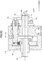
- Fig. 5C is a cross-sectional view of the chuck device 100 in a state where the workpiece holding claws 122 are closed and are brought close to the workpiece contact surface 115a.
- the rod 120 loosely inserted into the support body 130 swings around the support body 130, and the workpiece holding claw 122 of the rod 120 swings in the direction away from the central axis C of the chuck device 100.
- the chuck device 100 can receive a workpiece W in this state.
- a workpiece loading device brings the workpiece W into contact with the workpiece contact surface 115a of the chuck device 100.
- the rod 120 loosely inserted into the support body 130 swings around the support body 130, and the workpiece holding claw 122 of the rod 120 swings in the direction approaching the central axis C of the chuck device 100.
- the rod 120 is substantially parallel to the central axis C of the chuck device 100 (the forward/backward moving direction of the drive body 140), and the workpiece holding claws 122 are closed as shown in Fig. 5B .
- the direction in which the spring 153 urges the rod 120 is a direction such that the distance between the workpiece holding claws 122 of the rod 120 becomes shorter.
- the rod body 120 moves backward in the Z direction in a state where the rod body 120 is kept parallel to the central axis C of the chuck device 100 (that is, the forward/backward moving direction of the drive body 140). Then, the side end surface 122cb of the workpiece holding claw 122 is brought into contact with the workpiece W as shown in Fig. 5C , and the workpiece W is held by the claw portion 122c of the workpiece holding claw 122 and the workpiece contact surface 115a. That is, the workpiece W is held in the thickness direction of the workpiece W.
- the rod swing mechanism is composed of the guide groove 121a of the rod 120, the protrusion 114a of the housing 110, the support body 130, the drive body 140 and the like, and swings the three rods 120 integrally.
- the plurality of rods 120 integrally swing so that the workpiece holding claws 122 are moved away from the workpiece contact surface 115a of the housing 110 and moved away from each other, and when holding the workpiece W, after the plurality of rods 120 integrally swing so that the workpiece holding claws 122 are brought close to the workpiece contact surface 115a of the housing 110 and brought close to each other, the plurality of rods 120 move integrally in parallel with the forward/backward moving direction of the drive body 140 to bring the workpiece holding claws 122 into contact with the workpiece W.
- the workpiece W can be held without being deformed.
- the rod 120 and the drive body 140 are connected by the spring 153 that urges the rod 120 in the direction so that the distance between the workpiece holding claws 122 of the rod 120 becomes shorter, even if a force in the direction of increasing the distance between the workpiece holding claws 122 of the rod 120 is applied to the workpiece holding claws 122 while the workpiece holding claws 122 of the rod are being brought close to the workpiece contact surface 115a, the plurality of rods 120 can be kept parallel to each other while the workpiece holding claw 122 of the rod 120 is brought close to the workpiece contact surface 115a because the urging force by the spring 153 is applied to the rod 120.
- the machine tool 10 is provided with one machining module moving mechanism 13, one machining module 15 and one chuck device 100.
- the number of each component is not limited to that in the present example.
- the chuck device 100 is not movable in the X direction in the machine tool 10.
- the chuck device may be movable in the X direction.
- the number of rods 120 of the chuck device 100 is three.
- the number of rods is not limited to three as long as the number of rods is plural.
- the number of support bodies is not limited as well as the number of the rods.
- the rod swing mechanism is composed of the guide groove 121a of the rod 120 and the protrusion 114a of the housing 110.
- the protrusion may be provided on the rod side and the guide groove may be provided on the housing side.
- the shape of the workpiece may be any shape in a plan view as long as the thickness is sufficiently smaller than the width and height.
Landscapes
- Engineering & Computer Science (AREA)
- Mechanical Engineering (AREA)
- Gripping On Spindles (AREA)
Abstract
Description
- The present invention relates to a chuck device for holding a workpiece supplied to a machine tool, and more particularly to a chuck device provided with a plurality of workpiece holding claws.
- Conventionally, as a chuck device for gripping a workpiece, a workpiece chuck device is known which comprises: a chuck main body; a reference fixing claw that is fixed to one end side of the chuck main body and is for supporting one end of the workpiece; a movable claw that is provided on one end side of the chuck main body so as to be able to be opened and closed with respect to the reference fixing claw and is for supporting one end portion of the workpiece; drive means for opening and closing the movable claw; and a stopper for supporting the other end of the workpiece (for example, in the patent literature 1).
- [Patent Literature 1]
JP 2004-154876 A - In the workpiece chuck device described above, the side of the workpiece is clamped by the claws. Therefore, when the workpiece is a plate material, the workpiece may be deformed or buckled.
- Therefore, the present invention is for solving the problem of the prior art as described above, that is, the object of the present invention is to provide a chuck device for holding a plate material workpiece supplied to a machine tool without deforming the workpiece.
- Firstly, the present invention is characterized by a chuck device comprising: a plurality of rods provided with workpiece holding claws for holding a workpiece supplied to a machine tool; a support body for supporting each of the plurality of rods; a housing for swingably accommodating each of the plurality of rods around the support body; and a drive body for integrally moving forward and backward the plurality of rods with respect to the housing, wherein the housing has a workpiece contact surface that is arranged so as to face the workpiece holding claws, wherein when holding of the workpiece is released, the plurality of rods integrally swing so that the workpiece holding claws are moved away from the workpiece contact surface of the housing and moved away from each other, and wherein when holding the workpiece, after the plurality of rods integrally swing so that the workpiece holding claws are brought close to the workpiece contact surface of the housing and brought close to each other, the plurality of rods move integrally in parallel with the forward/backward moving direction of the drive body to bring the workpiece holding claws into contact with the workpiece.
- Secondly, the present invention is characterized in that the chuck device is provided with a rod swing mechanism for swinging each of the plurality of rods around the support body, the rod swing mechanism has a guide groove and a protrusion for engaging with the guide groove, when the protrusion and the guide groove are engaged with each other, the rod is parallel to the forward/backward moving direction of the drive body, and when the protrusion and the guide groove are not engaged with each other, the rod is tilted with respect to the forward/backward moving direction of the drive body.
- Thirdly, the present invention is characterized in that the guide groove of the rod swing mechanism is formed in the rod, and the protrusion of the rod swing mechanism is formed in the housing.
- Fourthly, the present invention is characterized in that an elastic body, which urges the rod so that each of the workpiece holding claws of the plurality of rods is brought close to each other, is interposed between the rod and the drive body.
- By adopting the chuck device according to the present invention, the following effects can be obtained.
- (1) When holding of the workpiece is released, the plurality of rods integrally swing so that the workpiece holding claws are moved away from the workpiece contact surface of the housing and moved away from each other. Therefore, since the workpiece is held in the forward/backward moving direction of the drive body, which is the thickness direction of the workpiece, in a case where the workpiece is a plate material, the workpiece can be held without being deformed.
- (2) When the protrusion and the guide groove are engaged with each other, the rod is parallel to the forward/backward moving direction of the drive body, and when the protrusion and the guide groove are not engaged with each other, the rod is tilted with respect to the forward/backward moving direction of the drive body. Therefore, the rod can be made swingable only by providing a guide groove and a protrusion, so that the rod can be made swingable with a simple configuration.
- (3) The guide groove of the rod swing mechanism is formed in the rod, and the protrusion of the rod swing mechanism is formed in the housing. Therefore, since the rod does not easily come into contact with the housing when the rod is accommodated in the housing, the chuck device can be manufactured more easily than in the case where the protrusion of the rod swing mechanism is formed on the rod.
- (4) An elastic body, which urges the rod so that each of the workpiece holding claws of the plurality of rods is brought close to each other, is interposed between the rod and the drive body. Therefore, even if a force in the direction of increasing the distance between the workpiece holding claws of the rod is applied to the workpiece holding claws while the workpiece holding claws of the rod are being brought close to the workpiece contact surface, since the urging force by the elastic body is applied to the rod, the plurality of rods can be kept parallel to each other while the workpiece holding claw of the rod is brought close to the workpiece contact surface.
-
-
Fig. 1 is a perspective view of a machine tool in which a chuck device according to the example of the present invention is incorporated. -
Fig. 2 is a plan view of a machining chamber in the machine tool shown inFig. 1 . -
Fig. 3A is a perspective view showing the chuck device according to the example of the present invention. -
Fig. 3B is a perspective view showing the inside of the chuck device shown inFig. 3A . -
Fig. 4 is a sectional view taken along the line IV-IV inFig. 3A . -
Fig. 5A is a cross-sectional view of the chuck device in a state where the workpiece holding claws are opened. -
Fig. 5B is a cross-sectional view of the chuck device in a state where the workpiece holding claws are closed and the workpiece is held. -
Fig. 5C is a cross-sectional view of the chuck device in a state where the workpiece holding claws are closed and are brought close to the workpiece contact surface. - The specific embodiment of the present invention may be arbitrary as long as a chuck device comprises: a plurality of rods provided with workpiece holding claws for holding a workpiece supplied to a machine tool; a support body for supporting each of the plurality of rods; a housing for swingably accommodating each of the plurality of rods around the support body; and a drive body for integrally moving forward and backward the plurality of rods with respect to the housing, wherein the housing has a workpiece contact surface that is arranged so as to face the workpiece holding claws, wherein when holding of the workpiece is released, the plurality of rods integrally swing so that the workpiece holding claws are moved away from the workpiece contact surface of the housing and moved away from each other, and wherein when holding the workpiece, after the plurality of rods integrally swing so that the workpiece holding claws are brought close to the workpiece contact surface of the housing and brought close to each other, the plurality of rods move integrally in parallel with the forward/backward moving direction of the drive body to bring the workpiece holding claws into contact with the workpiece, so that, in a case where the workpiece supplied to the machine tool is a plate material, the workpiece can be held without being deformed.
- Hereinafter, a chuck device according to an example of the present invention will be described with reference to
Figs. 1 to 5C . - First, the summary of a
machine tool 10 in which achuck device 100 according to the example of the present invention is incorporated will be described with reference toFigs. 1 and2 . -
Fig. 1 is a perspective view of themachine tool 10 in which thechuck device 100 according to the example of the present invention is incorporated, andFig. 2 is a plan view of a machining chamber in the machine tool shown inFig. 1 . - The
machine tool 10 has a plurality of machining modules, and as shown inFig. 1 , has a slidingdoor 12 on the front side for ensuring access to amachining chamber 11 in which the workpiece is processed. - In the
machining chamber 11, as shown inFig. 2 , a machiningmodule moving mechanism 13 is provided on abed 14. - The machining
module moving mechanism 13 is movable in the Y direction on thebed 14, and amachining module 15 is mounted on the machiningmodule moving mechanism 13 so as to be movable in the Z direction. - A tool post (not shown) and the
chuck device 100 for holding a workpiece supplied to themachine tool 10 are attached to themachining module 15. - Next, the
chuck device 100 according to the example of the present invention will be described with reference toFigs. 3A ,3B and4 . -
Fig. 3A is a perspective view showing thechuck device 100 according to the example of the present invention,Fig. 3B is a perspective view showing the inside of thechuck device 100 shown inFig. 3A , andFig. 4 is a sectional view taken along the line IV-IV inFig. 3A . - As shown in
Fig. 3A , thechuck device 100 has a columnar shape, and the rear end side thereof is connected to themachining module 15. - The major axis direction of the
chuck device 100 corresponds to the Z direction, and the direction orthogonal to the Z direction and the X direction (vertical direction) corresponds to the Y direction. - As shown in
Figs. 3A ,3B and4 , thechuck device 100 includes ahousing 110 that is coupled to themachining module 15 via adrive body 140 described later. - The
housing 110 includes abase 111, a housingmain body 112 attached to thebase 111, asleeve 113 for slidably holding arod 120 described later, anengagement member 114 for engaging with aguide groove 121a of therod 120 described later, a columnar receivingmember 115 for receiving the workpiece, and a columnarsupport body retainer 116 for preventing asupport body 130, which is inserted into the housingmain body 112 and will be described later, from coming off from the housingmain body 112. - The
base 111 is a disk-shaped member, and a throughhole 111a extending in the Z direction is formed at the center thereof. - The housing
main body 112 is a columnar member and is fixed to thebase 111 by bolts (not shown). - A
cylindrical recess 112a extending in the Z direction is formed on the rear end side of the housingmain body 112, and a drive body moving space V for allowing thedrive body 140 described later to move forward and backward is formed between therecess 112a and thebase 111. - Further, the housing
main body 112 is formed with three throughholes 112b extending in the Z direction and communicating with therecess 112a. - The central axes of the through
holes 112b are substantially parallel to the central axis C of thechuck device 100 and are provided on a single circumference whose center is the central axis C. - The through
holes 112b are formed at equal intervals (120-degree intervals in the present example) when viewed from the Z direction. - Further, on a side
peripheral surface 112c of the housingmain body 112, a supportbody insertion hole 112d, which is for inserting thesupport body 130 described later, and an engagementmember insertion hole 112e, which is for inserting theengagement member 114, are formed in the same number as the throughholes 112b. - Further, a columnar receiving
member accommodating recess 112g for accommodating the rear end portion of the receivingmember 115 is formed on afront surface 112f of the housingmain body 112. - The
sleeve 113 has a cylindrical sleevemain body 113a for being inserted into the throughhole 112b of the housingmain body 112 and engaging with thesupport body 130 described later, a sealingmember 113b for sealing the gap between the sleevemain body 113a and the housingmain body 112, and a retainingring 113c for preventing the sealingmember 113b from coming off the sleevemain body 113a. - The
engagement member 114 is a columnar member, is inserted into the engagementmember insertion hole 112e of the housingmain body 112, and is fixed to the housingmain body 112. - A V-shaped
protrusion 114a (viewed from the Z direction) is formed at the tip (on the central axis C side) of theengagement member 114. - The receiving
member 115 is appropriately selected according to the thickness of the workpiece and is inserted and fixed in the receivingmember accommodating recess 112g. - Further, a planar
workpiece contact surface 115a orthogonal to the Z direction is formed at the front end of the receivingmember 115. - The
support body retainer 116 is inserted into the supportbody insertion hole 112d after thesupport body 130 described later is inserted into the supportbody insertion hole 112d. - Further, as shown in
Figs. 3B and4 , thechuck device 100 includes threerods 120 that are accommodated in thehousing 110 and are movable forward and backward in thehousing 110, the threesupport bodies 130 mounted on thehousing 110, thedrive body 140 that is mounted on the hosing 110 and moves forward and backward the threerods 120 integrally, and acoupling mechanism 150 that couples therods 120 and thedrive body 140 and swings the threerods 120 integrally. - The
rod 120 has a columnar rodmain body 121 that is slidable in thesupport body 130, and aworkpiece holding claw 122 coupled to the tip of the rodmain body 121 for holding a workpiece. - The rod
main body 121 is formed with theguide groove 121a extending in the Z direction (that is, the direction in which the central axis C of thechuck device 100 extends) on the surface that faces an innerperipheral surface 112h of the housingmain body 112. - The
workpiece holding claw 122 can be replaced with respect to the rodmain body 121 depending on the size of the workpiece to be held, and protrudes from thehousing 110. - The
workpiece holding claw 122 is composed of anarm portion 122a that is coupled to the rodmain body 121 and extends toward the central axis C of thechuck device 100, aworkpiece contact portion 122b that extends from the tip of thearm portion 122a to the front substantially parallel to the central axis C, and aclaw portion 122c that extends from the tip of theworkpiece contact portion 122b toward the central axis C and faces theworkpiece contact surface 115a of thehousing 110 when holding the workpiece. - The
support body 130 is a columnar member and swingable with respect to the housingmain body 112. - Therefore, the
housing 110 swingably accommodates eachrod 120 via eachsupport body 130. - Further, the
support body 130 is formed with a throughhole 131 in the radial direction. - The diameter of the through
hole 131 is substantially equal to the diameter of the sleevemain body 113a and the rodmain body 121. - Therefore, the
support body 130 supports therod 120 in a loosely inserted state. - The
drive body 140 has adrive shaft 141 that moves forward and backward along the central axis C of thechuck device 100 and is inserted through the housingmain body 112, acoupling member 142 through which thedrive shaft 141 is inserted, and aretainer 143 through which thedrive shaft 141 is inserted and for preventing thecoupling member 142 from coming off from thedrive shaft 141. - One end side of the
drive shaft 141 is coupled to themachining module 15, and the other end side is inserted into the housingmain body 112. - As a result, the
drive shaft 141 is movable forward and backward with respect to thehousing 110.
thecoupling member 142 is a triangular columnar member, and arod holding portion 142a protrudes from each side surface. - The
rod holding portion 142a is U-shaped when viewed from the Z direction, and accommodates the rodmain body 121. - A pin insertion hole 142aa is formed on a surface of the
rod holding portion 142a, which faces the rodmain body 121. - The
coupling mechanism 150 has acoupling pin 151 for being inserted into therod 120 and thedrive body 140, aset screw 152 for preventing thecoupling pin 151 from coming off, and a spring (elastic body) interposed between therod 120 and thedrive body 140. - The
coupling pin 151 is inserted through the pin insertion hole 142aa of thedrive body 140 and a throughhole 121b formed on the back side of the rodmain body 121. - The
set screw 152 is screwed into a screw hole 121c orthogonal to the throughhole 121b formed in the rodmain body 121 and is in contact with thecoupling pin 151. - A
spring 153 urges therod 120 in the direction away from the central axis C of thechuck device 100. - Next, holding of the workpiece by the rod swing mechanism of the
chuck device 100 according to the example of the present invention configured as described above will be described with reference toFigs. 4 ,5A to 5C . -
Fig. 5A is a cross-sectional view of thechuck device 100 in a state where theworkpiece holding claws 122 are opened,Fig. 5B is a cross-sectional view of thechuck device 100 in a state where the workpiece holding claws122 are closed and the workpiece is held, andFig. 5C is a cross-sectional view of thechuck device 100 in a state where theworkpiece holding claws 122 are closed and are brought close to theworkpiece contact surface 115a. - First, when the
drive body 140 is moved forward in the Z direction from the state where theworkpiece holding claw 122 is closed as shown inFig. 4 (the state where therod 120 is substantially parallel to the central axis C of the chuck device 100), the threerods 120 coupled to thedrive body 140 by thecoupling mechanism 150 also move forward in the Z direction. - When the
protrusion 114a of theengagement member 114 climbs a rear end slope 121d (seeFig. 5A ) formed on the rear end side of theguide groove 121a of therod 120, since theengagement member 114 is fixed to the housingmain body 112, therod 120 moves to the central axis C side of thechuck device 100 due to theengagement member 114. - At this time, since the
support body 130 is swingable with respect to the housing 110 (housing main body 112), therod 120 loosely inserted into thesupport body 130 swings around thesupport body 130, and theworkpiece holding claw 122 of therod 120 swings in the direction away from the central axis C of thechuck device 100. - Therefore, when the
protrusion 114a climbs the rear end slope 121d of therod 120 and theprotrusion 114a and theguide groove 121a are not engaged, therod 120 tilts with respect to the central axis C of the chuck device 100 (the forward/backward moving direction of the drive body 140), and theworkpiece holding claw 122 is opened as shown inFIG. 5A (a state where an inner end surface 122ca of theworkpiece holding claw 122, which is parallel to the central axis C of thechuck device 100, is widely open than the receivingmember 115 when viewed from the Z direction). - The
chuck device 100 can receive a workpiece W in this state. - Then, a workpiece loading device (not shown) brings the workpiece W into contact with the
workpiece contact surface 115a of thechuck device 100. - When the
drive body 140 is moved backward in the Z direction from this state, the threerods 120 coupled to thedrive body 140 by thecoupling mechanism 150 also move backward in the Z direction. - When the
protrusion 114a of theengagement member 114 descends the rear end slope 121d of therod 120, since theprotrusion 114a of theengagement member 114 is fixed to the housingmain body 112 and therod 120 is urged to the outer peripheral side of the housingmain body 112 by thespring 153, therod 120 moves to the side away from the central axis C of thechuck device 100 due to theengagement member 114. - At this time, since the
support body 130 is swingable with respect to the housing 110 (housing main body 112), therod 120 loosely inserted into thesupport body 130 swings around thesupport body 130, and theworkpiece holding claw 122 of therod 120 swings in the direction approaching the central axis C of thechuck device 100. - Therefore, when the
protrusion 114a descends the rear end slope 121d of therod 120 and theprotrusion 114a and theguide groove 121a are engaged, therod 120 is substantially parallel to the central axis C of the chuck device 100 (the forward/backward moving direction of the drive body 140), and theworkpiece holding claws 122 are closed as shown inFig. 5B . - Further, the direction in which the
spring 153 urges therod 120 is a direction such that the distance between theworkpiece holding claws 122 of therod 120 becomes shorter. - When the
drive body 140 is further moved backward in the Z direction from this state, the threerods 120 coupled to thedrive body 140 by thecoupling mechanism 150 are also further moved rearward in the Z direction. - At this time, since the
protrusion 114a of theengagement member 114 is fixed to the housingmain body 112, when therod 120 moves backward in the Z direction, theprotrusion 114a of theengagement member 114 slides in theguide groove 121a in a state of engaging with theguide groove 121a of therod 120. - As a result, the
rod body 120 moves backward in the Z direction in a state where therod body 120 is kept parallel to the central axis C of the chuck device 100 (that is, the forward/backward moving direction of the drive body 140). Then, the side end surface 122cb of theworkpiece holding claw 122 is brought into contact with the workpiece W as shown inFig. 5C , and the workpiece W is held by theclaw portion 122c of theworkpiece holding claw 122 and theworkpiece contact surface 115a. That is, the workpiece W is held in the thickness direction of the workpiece W. - When the
rod 120 moves backward in the Z direction while therod body 120 is kept parallel to the central axis C of thechuck device 100, since therod 120 is urged to the outer peripheral side of the housingmain body 112 by thespring 153, therod 120 continues to be urged in the direction so that the distance between theworkpiece holding claws 122 of therod 120 becomes shorter. - Therefore, the rod swing mechanism is composed of the
guide groove 121a of therod 120, theprotrusion 114a of thehousing 110, thesupport body 130, thedrive body 140 and the like, and swings the threerods 120 integrally. - Then, by adopting this rod swing mechanism, when holding of the workpiece W is released, the plurality of
rods 120 integrally swing so that theworkpiece holding claws 122 are moved away from theworkpiece contact surface 115a of thehousing 110 and moved away from each other, and when holding the workpiece W, after the plurality ofrods 120 integrally swing so that theworkpiece holding claws 122 are brought close to theworkpiece contact surface 115a of thehousing 110 and brought close to each other, the plurality ofrods 120 move integrally in parallel with the forward/backward moving direction of thedrive body 140 to bring theworkpiece holding claws 122 into contact with the workpiece W. - As a result, even if the workpiece W is a thin plate material, the workpiece W can be held without being deformed.
- Further, since the
rod 120 and thedrive body 140 are connected by thespring 153 that urges therod 120 in the direction so that the distance between theworkpiece holding claws 122 of therod 120 becomes shorter, even if a force in the direction of increasing the distance between theworkpiece holding claws 122 of therod 120 is applied to theworkpiece holding claws 122 while theworkpiece holding claws 122 of the rod are being brought close to theworkpiece contact surface 115a, the plurality ofrods 120 can be kept parallel to each other while theworkpiece holding claw 122 of therod 120 is brought close to theworkpiece contact surface 115a because the urging force by thespring 153 is applied to therod 120. - The example of the present invention has been described above. However, the present invention is not limited to the above example.
- For example, in the present example, the
machine tool 10 is provided with one machiningmodule moving mechanism 13, onemachining module 15 and onechuck device 100. However, the number of each component is not limited to that in the present example. - For example, in the present example, the
chuck device 100 is not movable in the X direction in themachine tool 10. However, the chuck device may be movable in the X direction. - For example, in the present example, the number of
rods 120 of thechuck device 100 is three. However, the number of rods is not limited to three as long as the number of rods is plural. - The number of support bodies is not limited as well as the number of the rods.
- For example, in the present example, the rod swing mechanism is composed of the
guide groove 121a of therod 120 and theprotrusion 114a of thehousing 110. However, the protrusion may be provided on the rod side and the guide groove may be provided on the housing side. - For example, the shape of the workpiece may be any shape in a plan view as long as the thickness is sufficiently smaller than the width and height.
-
- 10
- machine tool
- 11
- machining chamber
- 12
- door
- 13
- machining module moving mechanism
- 14
- bed
- 15
- machining module
- 100
- chuck device
- 110
- housing
- 111
- base
- 111a
- through hole
- 112
- housing main body
- 112a
- recess
- 112b
- through hole
- 112c
- side peripheral surface
- 112d
- support body insertion hole
- 112e
- engagement member insertion hole
- 112f
- front surface
- 112g
- receiving member accommodating recess
- 112h
- inner peripheral surface
- 113
- sleeve
- 113a
- sleeve main body
- 113b
- sealing member
- 113c
- retaining ring
- 114
- engagement member
- 114a
- protrusion
- 115
- receiving member
- 115a
- workpiece contact surface
- 116
- support body retainer
- 120
- rod
- 121
- rod main body
- 121a
- guide groove
- 121b
- through hole
- 121c
- screw hole
- 121d
- rear end slope
- 122
- workpiece holding claw
- 122a
- arm portion
- 122b
- workpiece contact portion
- 122c
- claw portion
- 122ca
- inner end surface
- 122cb
- side end surface
- 130
- support body
- 131
- through hole
- 140
- drive body
- 141
- drive shaft
- 142
- coupling member
- 142a
- rod holding portion
- 142aa
- pin insertion hole
- 143
- retainer
- 150
- coupling mechanism
- 151
- coupling pin
- 152
- set screw
- 153
- spring (elastic body)
- V
- drive body moving space
- C
- central axis
- W
- workpiece
Claims (4)
- A chuck device comprising:a plurality of rods provided with workpiece holding claws for holding a workpiece supplied to a machine tool;a support body for supporting each of the plurality of rods;a housing for swingably accommodating each of the plurality of rods around the support body; anda drive body for integrally moving forward and backward the plurality of rods with respect to the housing, whereinthe housing has a workpiece contact surface that is arranged so as to face the workpiece holding claws, whereinwhen holding of the workpiece is released, the plurality of rods integrally swing so that the workpiece holding claws are moved away from the workpiece contact surface of the housing and moved away from each other, and whereinwhen holding the workpiece, after the plurality of rods integrally swing so that the workpiece holding claws are brought close to the workpiece contact surface of the housing and brought close to each other, the plurality of rods move integrally in parallel with the forward/backward moving direction of the drive body to bring the workpiece holding claws into contact with the workpiece.
- The chuck device according to claim 1, wherein the chuck device is provided with a rod swing mechanism for swinging each of the plurality of rods around the support body,the rod swing mechanism has a guide groove and a protrusion for engaging with the guide groove,when the protrusion and the guide groove are engaged with each other, the rod is parallel to the forward/backward moving direction of the drive body, andwhen the protrusion and the guide groove are not engaged with each other, the rod is tilted with respect to the forward/backward moving direction of the drive body.
- The chuck device according to claim 2, wherein the guide groove of the rod swing mechanism is formed in the rod, and
the protrusion of the rod swing mechanism is formed in the housing. - The chuck device according to claim 3, wherein an elastic body, which urges the rod so that each of the workpiece holding claws of the plurality of rods is brought close to each other, is interposed between the rod and the drive body.
Applications Claiming Priority (2)
| Application Number | Priority Date | Filing Date | Title |
|---|---|---|---|
| JP2019209243A JP7467080B2 (en) | 2019-11-20 | 2019-11-20 | Chuck Device |
| PCT/JP2020/041489 WO2021100489A1 (en) | 2019-11-20 | 2020-11-06 | Chuck device |
Publications (2)
| Publication Number | Publication Date |
|---|---|
| EP4023377A1 true EP4023377A1 (en) | 2022-07-06 |
| EP4023377A4 EP4023377A4 (en) | 2023-09-06 |
Family
ID=75963261
Family Applications (1)
| Application Number | Title | Priority Date | Filing Date |
|---|---|---|---|
| EP20888897.4A Pending EP4023377A4 (en) | 2019-11-20 | 2020-11-06 | Chuck device |
Country Status (7)
| Country | Link |
|---|---|
| US (1) | US12296394B2 (en) |
| EP (1) | EP4023377A4 (en) |
| JP (1) | JP7467080B2 (en) |
| KR (1) | KR20220093326A (en) |
| CN (1) | CN114761163B (en) |
| TW (1) | TWI857175B (en) |
| WO (1) | WO2021100489A1 (en) |
Families Citing this family (3)
| Publication number | Priority date | Publication date | Assignee | Title |
|---|---|---|---|---|
| CN115533146B (en) * | 2022-11-02 | 2023-12-19 | 昆山岱屹精密机械有限公司 | Machine tool claw disc for eccentric part |
| CN116475856B (en) * | 2023-05-09 | 2025-10-31 | 株洲圣达切削刀具有限公司 | Automatic center of grinding machine |
| CN117644410B (en) * | 2024-01-29 | 2024-04-26 | 象山申达轿车配件有限公司 | Oil distribution plate positioning and clamping device |
Family Cites Families (43)
| Publication number | Priority date | Publication date | Assignee | Title |
|---|---|---|---|---|
| US1812006A (en) * | 1926-12-27 | 1931-06-30 | Heald Machine Co | Chuck |
| US1823902A (en) * | 1926-12-27 | 1931-09-22 | Heald Machine Co | Chuck |
| US1882975A (en) * | 1929-12-10 | 1932-10-18 | Heald Machine Co | Chuck |
| US2361763A (en) * | 1943-03-15 | 1944-10-31 | Jack & Heintz Inc | Pneumatic finger chuck |
| US2865643A (en) * | 1957-06-27 | 1958-12-23 | John J Parker | Edge clamping chuck |
| US3420538A (en) * | 1966-01-21 | 1969-01-07 | Erickson Tool Co | Swivel finger chuck |
| JPS5813906U (en) * | 1981-07-17 | 1983-01-28 | 豊和工業株式会社 | finger chuck |
| JP2656047B2 (en) * | 1987-11-16 | 1997-09-24 | 寺坂 哲一 | Internal and external diameter processing chuck |
| JPH03277408A (en) * | 1990-03-23 | 1991-12-09 | Teikoku Chuck Kk | Chuck for processing thin wall work |
| JP2517463Y2 (en) * | 1990-05-25 | 1996-11-20 | 松本機械工業株式会社 | Finger chuck for wheel processing |
| FR2665092B1 (en) * | 1990-07-24 | 1995-02-03 | Gamet Precision | TIGHTENING CHUCK FOR MACHINE TOOL. |
| JPH0549207U (en) * | 1991-12-04 | 1993-06-29 | 帝国チャック株式会社 | Chuck for lathe |
| JP3183367B2 (en) * | 1993-03-08 | 2001-07-09 | 豊和工業株式会社 | Finger chuck |
| JP3059357B2 (en) * | 1995-03-27 | 2000-07-04 | 松本機械工業株式会社 | Work gripper moving device for finger chuck for wheel machining |
| JPH0957508A (en) * | 1995-08-24 | 1997-03-04 | Howa Mach Ltd | Finger chuck |
| JP3446416B2 (en) * | 1995-08-31 | 2003-09-16 | 豊和工業株式会社 | Finger chuck |
| DE69705597T2 (en) * | 1996-09-16 | 2002-04-18 | Howa Machinery, Ltd. | Interchangeable chuck system |
| FR2755049A1 (en) * | 1996-10-25 | 1998-04-30 | Ragonot | Compact gripping head for handling metal sheet |
| FR2781400B1 (en) * | 1998-07-27 | 2000-09-29 | Genus Technologies | CENTERING AND CLAMPING DEVICE, PARTICULARLY FOR PARTS OF AUTOMOTIVE BODYWORK |
| FR2788711B1 (en) * | 1999-01-25 | 2001-03-09 | Sandvik Tobler | ADAPTIVE TIGHTENING CHUCK |
| JP2001219309A (en) * | 2000-02-07 | 2001-08-14 | Howa Mach Ltd | Chuck |
| DE20003067U1 (en) | 2000-02-19 | 2000-04-20 | Röhm GmbH, 89567 Sontheim | Power operated lever chuck |
| JP3690987B2 (en) * | 2000-05-16 | 2005-08-31 | 有限会社志田製作所 | Work chucking device |
| TW557238B (en) * | 2001-07-18 | 2003-10-11 | Kitagawa Iron Works Co | Chuck with pull-in function |
| JP2004154876A (en) | 2002-11-05 | 2004-06-03 | Nisshin Kogyo Kk | Work chuck device |
| JP4135506B2 (en) | 2003-01-15 | 2008-08-20 | 豊和工業株式会社 | Drawdown chuck |
| FR2850306B1 (en) * | 2003-01-29 | 2006-01-20 | Sandvik Tobler | CHUCK PINCE |
| JP4288124B2 (en) * | 2003-09-04 | 2009-07-01 | 株式会社北川鉄工所 | Finger chuck |
| IL180448A0 (en) * | 2006-01-30 | 2007-06-03 | Tool Internat Ag F | Clamping apparatus |
| EP1862241B1 (en) * | 2006-06-03 | 2011-10-05 | SMW-AUTOBLOK Spannsysteme GmbH | Powered Chuck |
| US8534677B2 (en) * | 2007-02-27 | 2013-09-17 | Forkardt Inc. | Work-holding chuck with quick-release jaws |
| JP5049850B2 (en) * | 2008-04-02 | 2012-10-17 | 株式会社北川鉄工所 | Friction welding machine chuck device and work grip opening method |
| JP2009285780A (en) * | 2008-05-29 | 2009-12-10 | Howa Mach Ltd | Draw-down chuck |
| JP5644448B2 (en) * | 2010-12-06 | 2014-12-24 | 村田機械株式会社 | Chuck device |
| JP2013059826A (en) * | 2011-09-13 | 2013-04-04 | Nakamura Tome Precision Ind Co Ltd | Work grip tool and method of work handling of lathe turning machine |
| JP5861835B2 (en) * | 2012-06-13 | 2016-02-16 | 豊和工業株式会社 | Chuck |
| TWM441530U (en) * | 2012-06-28 | 2012-11-21 | Chiu Tai Precise Co Ltd | Improved structure of adjustable oil hydraulic soft jaw block |
| CN107624085B (en) * | 2016-05-16 | 2019-03-26 | 有限会社新沙泰克 | Chuck mechanism, guide jaws and working machines |
| CN106346032B (en) | 2016-11-17 | 2018-08-03 | 常州倍得福机械科技有限公司 | Axis processes retractable floating dog chuck |
| US20190329327A1 (en) * | 2016-11-24 | 2019-10-31 | Kitagawa Iron Works Co., Ltd | Chuck device |
| JP6888995B2 (en) | 2017-03-22 | 2021-06-18 | 株式会社北川鉄工所 | Chuck device |
| US11376697B2 (en) * | 2017-12-22 | 2022-07-05 | Citizen Watch Co., Ltd. | Tool holding device and machine tool |
| JPWO2019167927A1 (en) * | 2018-02-27 | 2021-02-04 | 株式会社北川鉄工所 | Chuck |
-
2019
- 2019-11-20 JP JP2019209243A patent/JP7467080B2/en active Active
-
2020
- 2020-11-06 CN CN202080078994.2A patent/CN114761163B/en active Active
- 2020-11-06 TW TW109138860A patent/TWI857175B/en active
- 2020-11-06 WO PCT/JP2020/041489 patent/WO2021100489A1/en not_active Ceased
- 2020-11-06 KR KR1020227016275A patent/KR20220093326A/en active Pending
- 2020-11-06 EP EP20888897.4A patent/EP4023377A4/en active Pending
- 2020-11-06 US US17/771,203 patent/US12296394B2/en active Active
Also Published As
| Publication number | Publication date |
|---|---|
| TW202120228A (en) | 2021-06-01 |
| WO2021100489A1 (en) | 2021-05-27 |
| JP7467080B2 (en) | 2024-04-15 |
| US20220355390A1 (en) | 2022-11-10 |
| US12296394B2 (en) | 2025-05-13 |
| KR20220093326A (en) | 2022-07-05 |
| TWI857175B (en) | 2024-10-01 |
| JP2021079491A (en) | 2021-05-27 |
| EP4023377A4 (en) | 2023-09-06 |
| CN114761163A (en) | 2022-07-15 |
| CN114761163B (en) | 2024-03-15 |
Similar Documents
| Publication | Publication Date | Title |
|---|---|---|
| US12296394B2 (en) | Chuck device | |
| US5709391A (en) | Bit mounting device | |
| KR102113464B1 (en) | Inlet type chuck | |
| US20190329327A1 (en) | Chuck device | |
| US8272646B2 (en) | Quick change jaw system for chucks | |
| KR102217778B1 (en) | Tool gripper arrangement | |
| US9393654B2 (en) | Instant clamping mechanism | |
| US11524377B2 (en) | Lockable tool clamp | |
| JPS63171488A (en) | Assembling device for magnetic disk cartridge | |
| JP3837629B2 (en) | Tool pot | |
| JP5779205B2 (en) | Assembling method with circlip, and guide jig for attaching circlip | |
| EP4131681B1 (en) | Rubber plug holding device and electric wire insertion device | |
| JPH10193225A (en) | Method and device for assembling torsion spring | |
| US5584638A (en) | Guided disk handling system | |
| CN109877781B (en) | A kind of torsion spring loading mechanism for trigger | |
| CN214933759U (en) | Non-magnetic battery supporting cup | |
| JP7733395B2 (en) | E-type retaining ring insertion tool and E-type retaining ring supply device | |
| KR100398134B1 (en) | Jig pin apparatus for fixing pannel | |
| JP6796455B2 (en) | Sample stand support | |
| JP2002283104A (en) | A device for supporting bars in the spindle of a machine tool | |
| JP4871094B2 (en) | Deformation workpiece chuck device | |
| JP7135247B2 (en) | Chuck device | |
| CN207824230U (en) | Positioning column mechanism | |
| JP7202101B2 (en) | Spindle unit and cutting equipment equipped with it | |
| JP2008030140A (en) | Machine Tools |
Legal Events
| Date | Code | Title | Description |
|---|---|---|---|
| STAA | Information on the status of an ep patent application or granted ep patent |
Free format text: STATUS: THE INTERNATIONAL PUBLICATION HAS BEEN MADE |
|
| PUAI | Public reference made under article 153(3) epc to a published international application that has entered the european phase |
Free format text: ORIGINAL CODE: 0009012 |
|
| STAA | Information on the status of an ep patent application or granted ep patent |
Free format text: STATUS: REQUEST FOR EXAMINATION WAS MADE |
|
| 17P | Request for examination filed |
Effective date: 20220401 |
|
| AK | Designated contracting states |
Kind code of ref document: A1 Designated state(s): AL AT BE BG CH CY CZ DE DK EE ES FI FR GB GR HR HU IE IS IT LI LT LU LV MC MK MT NL NO PL PT RO RS SE SI SK SM TR |
|
| DAV | Request for validation of the european patent (deleted) | ||
| DAX | Request for extension of the european patent (deleted) | ||
| REG | Reference to a national code |
Ref country code: DE Ref legal event code: R079 Free format text: PREVIOUS MAIN CLASS: B23B0031020000 Ipc: B23B0031180000 |
|
| A4 | Supplementary search report drawn up and despatched |
Effective date: 20230804 |
|
| RIC1 | Information provided on ipc code assigned before grant |
Ipc: B23B 31/19 20060101ALI20230731BHEP Ipc: B23B 31/18 20060101AFI20230731BHEP |
|
| RIN1 | Information on inventor provided before grant (corrected) |
Inventor name: SAKAI, MASAO Inventor name: NAKAZAWA, SAKAE |
|
| STAA | Information on the status of an ep patent application or granted ep patent |
Free format text: STATUS: EXAMINATION IS IN PROGRESS |
|
| 17Q | First examination report despatched |
Effective date: 20250404 |