EP4023271B1 - Disposable circuit for extracorporeal treatment of blood, apparatus for extracorporeal treatment of blood and associated method - Google Patents
Disposable circuit for extracorporeal treatment of blood, apparatus for extracorporeal treatment of blood and associated method Download PDFInfo
- Publication number
- EP4023271B1 EP4023271B1 EP20306706.1A EP20306706A EP4023271B1 EP 4023271 B1 EP4023271 B1 EP 4023271B1 EP 20306706 A EP20306706 A EP 20306706A EP 4023271 B1 EP4023271 B1 EP 4023271B1
- Authority
- EP
- European Patent Office
- Prior art keywords
- connector
- blood
- auxiliary
- circuit
- line
- Prior art date
- Legal status (The legal status is an assumption and is not a legal conclusion. Google has not performed a legal analysis and makes no representation as to the accuracy of the status listed.)
- Active
Links
Images


Classifications
-
- A—HUMAN NECESSITIES
- A61—MEDICAL OR VETERINARY SCIENCE; HYGIENE
- A61M—DEVICES FOR INTRODUCING MEDIA INTO, OR ONTO, THE BODY; DEVICES FOR TRANSDUCING BODY MEDIA OR FOR TAKING MEDIA FROM THE BODY; DEVICES FOR PRODUCING OR ENDING SLEEP OR STUPOR
- A61M1/00—Suction or pumping devices for medical purposes; Devices for carrying-off, for treatment of, or for carrying-over, body-liquids; Drainage systems
- A61M1/36—Other treatment of blood in a by-pass of the natural circulatory system, e.g. temperature adaptation, irradiation ; Extra-corporeal blood circuits
- A61M1/3621—Extra-corporeal blood circuits
- A61M1/3643—Priming, rinsing before or after use
- A61M1/3644—Mode of operation
-
- A—HUMAN NECESSITIES
- A61—MEDICAL OR VETERINARY SCIENCE; HYGIENE
- A61M—DEVICES FOR INTRODUCING MEDIA INTO, OR ONTO, THE BODY; DEVICES FOR TRANSDUCING BODY MEDIA OR FOR TAKING MEDIA FROM THE BODY; DEVICES FOR PRODUCING OR ENDING SLEEP OR STUPOR
- A61M1/00—Suction or pumping devices for medical purposes; Devices for carrying-off, for treatment of, or for carrying-over, body-liquids; Drainage systems
- A61M1/36—Other treatment of blood in a by-pass of the natural circulatory system, e.g. temperature adaptation, irradiation ; Extra-corporeal blood circuits
- A61M1/3621—Extra-corporeal blood circuits
- A61M1/3643—Priming, rinsing before or after use
- A61M1/3644—Mode of operation
- A61M1/3647—Mode of operation with recirculation of the priming solution
-
- A—HUMAN NECESSITIES
- A61—MEDICAL OR VETERINARY SCIENCE; HYGIENE
- A61M—DEVICES FOR INTRODUCING MEDIA INTO, OR ONTO, THE BODY; DEVICES FOR TRANSDUCING BODY MEDIA OR FOR TAKING MEDIA FROM THE BODY; DEVICES FOR PRODUCING OR ENDING SLEEP OR STUPOR
- A61M1/00—Suction or pumping devices for medical purposes; Devices for carrying-off, for treatment of, or for carrying-over, body-liquids; Drainage systems
- A61M1/36—Other treatment of blood in a by-pass of the natural circulatory system, e.g. temperature adaptation, irradiation ; Extra-corporeal blood circuits
- A61M1/3621—Extra-corporeal blood circuits
- A61M1/3653—Interfaces between patient blood circulation and extra-corporal blood circuit
-
- A—HUMAN NECESSITIES
- A61—MEDICAL OR VETERINARY SCIENCE; HYGIENE
- A61M—DEVICES FOR INTRODUCING MEDIA INTO, OR ONTO, THE BODY; DEVICES FOR TRANSDUCING BODY MEDIA OR FOR TAKING MEDIA FROM THE BODY; DEVICES FOR PRODUCING OR ENDING SLEEP OR STUPOR
- A61M1/00—Suction or pumping devices for medical purposes; Devices for carrying-off, for treatment of, or for carrying-over, body-liquids; Drainage systems
- A61M1/36—Other treatment of blood in a by-pass of the natural circulatory system, e.g. temperature adaptation, irradiation ; Extra-corporeal blood circuits
- A61M1/3621—Extra-corporeal blood circuits
- A61M1/367—Circuit parts not covered by the preceding subgroups of group A61M1/3621
-
- A—HUMAN NECESSITIES
- A61—MEDICAL OR VETERINARY SCIENCE; HYGIENE
- A61M—DEVICES FOR INTRODUCING MEDIA INTO, OR ONTO, THE BODY; DEVICES FOR TRANSDUCING BODY MEDIA OR FOR TAKING MEDIA FROM THE BODY; DEVICES FOR PRODUCING OR ENDING SLEEP OR STUPOR
- A61M39/00—Tubes, tube connectors, tube couplings, valves, access sites or the like, specially adapted for medical use
- A61M39/10—Tube connectors; Tube couplings
Definitions
- the present disclosure relates to a disposable circuit for extracorporeal treatment of blood configurable for fluid recirculation, to an apparatus for extracorporeal treatment of blood, a method of blood flow recirculation in the disposable circuit and an associated computer program product.
- the disposable circuit is particularly suitable for temporary disconnection of a patient from the apparatus for extracorporeal treatment of blood and subsequent reconnection to the same disposable circuit for treatment prosecution.
- Extracorporeal blood treatment involves removing blood from a patient, treating the blood externally to the patient, and returning the treated blood to the patient.
- Extracorporeal blood treatment is typically used to extract undesirable matter or molecules from the patient's blood and/or add desirable matter or molecules to the blood.
- Extracorporeal blood treatment is used with patients unable to effectively remove matter from their blood, such as when a patient has suffered temporary or permanent kidney failure. These patients and other patients may undergo extracorporeal blood treatment to add or remove matter to their blood, to maintain an acid/base balance or to remove excess body fluids, for example.
- Extracorporeal blood treatment is typically accomplished by removing the blood from the patient in e.g. a continuous flow, introducing the blood into a primary chamber, also referred to as blood chamber, of a filtration unit (such as a dialyzer or a hemofilter) where the blood is allowed to flow past a semipermeable membrane.
- a primary chamber also referred to as blood chamber
- a filtration unit such as a dialyzer or a hemofilter
- the semipermeable membrane selectively allows matter in the blood to cross the membrane from the primary chamber into a secondary chamber and also selectively allows matter in the secondary chamber to cross the membrane into the blood in the primary chamber, depending on the type of treatment.
- a number of different types of extracorporeal blood treatments may be performed.
- an ultrafiltration (UF) treatment undesirable matter is removed from the blood by convection across the membrane into the secondary chamber.
- UF ultrafiltration
- HF hemofiltration
- the blood flows past the semipermeable membrane as in UF and desirable matter is added to the blood, typically by dispensing a fluid into the blood either before and/or after it passes through the filtration unit and before it is returned to the patient.
- a hemodialysis (HD) treatment a secondary fluid containing desirable matter is introduced into the secondary chamber of the filtration unit. Undesirable matter from the blood crosses the semipermeable membrane into the secondary fluid and desirable matter from the secondary fluid may cross the membrane into the blood.
- HDF hemodiafiltration
- blood and secondary fluid exchange matter as in HD and, in addition, matter is added to the blood, typically by dispensing a fluid into the treated blood before its return to the patient as in HF.
- Some treatments for patients may involve very long procedures wherein blood is treated for several days or even weeks; this is the case of continuous renal replacement therapies CRRT wherein the blood treatment apparatuses may be operated continuously for some days.
- the treatment is for continuous renal replacement, or for acute or chronic patients, there may be cases wherein the patient may need to be disconnected from the apparatus when the treatment is still not yet completed. This is the case for instance when the patient shall be subjected to medical exams to be performed outside the renal unit room or when an intervention on the vascular access shall be suddenly performed.
- Disconnecting and reconnecting the blood treatment apparatus to the blood circuit lines requires disconnecting these lines from the patient, in particular from a venous connector and an arterial connector arranged on the ends of the blood circuit apparatus (for example the patient is disconnected from respective venous and arterial needles inserted into the fistula - chronic treatments - or from a catheter fixed to the patient - acute treatments).
- Disconnection and reconnection of blood circuit of the blood treatment apparatuses shall be performed in sterile conditions, and this requires a qualified operator who may not interact with the control unit of the apparatus, which is typically not sterile. Stagnant blood in the blood circuit of the apparatus may coagulate; therefore, the blood treatment apparatus shall be left non-operative for very short times to avoid harming the patient safety.
- complete substitution of disposable circuits during temporary interruption of the therapy should be avoided at least for an economic reason; in this latter case, substitution of disposable circuits would imply significantly higher costs for each single treatment.
- Document US9713670 discloses a method for temporarily interrupting an extracorporeal treatment of blood of a patient by use of a blood treatment apparatus.
- the method comprises activating a control device configured to bring the blood treatment apparatus into a state in which the blood treatment session of the patient can be interrupted with the intention to continue the blood treatment session.
- the ends of the blood lines are disconnected from the patient and connected through an 'Y' connector to the same saline solution bag. The fluid is then recirculated inside the blood circuit.
- a pump is aspirating liquid from a venous reservoir for sending it to a heater and oxygenator unit.
- An outlet of the oxygenator unit is connected to a first arterial Y-connector.
- the mainstream outlet of the first arterial Y-connector is connected via an arterial trunk conduit to the patient's arterial catheter.
- blood or liquid coming from the patient via a venous catheter passes a venous front conduit and a venous Y-connector.
- a shunt inlet of the venous Y-connector is connected to a shunting outlet of the first arterial Y-connector by means of a shunt conduit.
- the mainstream outlet is connected to the venous reservoir with an integrated filter.
- a third port of connector may send liquid to a collecting bag.
- Document US6913588 shows an extracorporeal circuit connected in line with an existing hemofiltration system.
- the hemofiltration system emerges from a patient venous connection in a conduit provided with a blood pump.
- An anticoagulant and replacement fluids are infused into the conduit with a pump to prevent blood coagulation and replace blood volume lost as a waste product.
- Blood enters a hemofilter where ultrafiltrate is separated from the blood. After filtration, blood leaves the hemofilter along a bloodline, through a shunt and a conduit, returning to a patient arterial system. Ultrafiltrate leaves the hemofilter at an ultrafiltrate port through the ultrafiltrate conduit.
- Document US5630946 discloses a method for removing leukocytes from the blood in an extracorporeal circuit by passing a leukocyte containing blood from a patient into a container, passing a portion of biological fluid from the container through a recirculation loop including a filter assembly for removing leukocytes and moving the portion of leukocyte-depleted blood into the container; additional blood with leukocyte is transferred from a patient into the container so that the additional blood is mixed with leukocyte depleted blood in the container to provide a mixture and then a portion of the mixture is sent to the patient while passing another portion of the mixture through the recirculation loop.
- Document US5895368 discloses an extracorporeal blood set for use in hemodialysis.
- the set comprises an arterial line connected to a dialyzer and from there to a venous set.
- Arterial line has a patient connector and a tubing with a roller pump tubing and distal end connector for connection with dialyzer.
- T-connector carries a branching tube which comprises an integrally and permanently attached set for connecting at its remote end to a source of saline.
- Branching solution set carries a Y member, to which is connected further branch tubing, which is terminated with a female luer lock connector.
- a disposable circuit for extracorporeal treatment of blood which allows a safe reconnection of the patient to the apparatus, and a safe reintroduction of the fluid and/or blood still present in the apparatus into the circulatory apparatus of the patient when this latter is reconnected to the treatment machine. It is a further object of embodiments of the disclosure to provide a disposable circuit that, when the patient is disconnected from the apparatus, is configurable in a configuration which prevents stagnation and/or reduces the risk of coagulation of the blood still present therein.
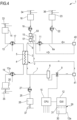
- Non-limiting embodiments of an apparatus 1 for extracorporeal treatment of blood - which may implement innovative aspects of the invention - are shown in figures.
- same components are identified by same reference numerals.
- Figure 1 shows an apparatus 1 designed for delivering extracorporeal blood treatments to patients, such as treatment for removing unwanted matter from the blood thereof.
- an apparatus for extracorporeal blood treatment by hemoperfusion and/or or ExtraCorporeal CO2 Removal are also included in the scope of the invention.
- the apparatus 1 is conceived for running of at least one of the following treatments: hemodialysis (HD), hemofiltration with pre-dilution (HF pre ), hemofiltration with post-dilution (HF post ), hemofiltration with both pre-dilution and post-dilution (HF pre-post ), hemodiafiltration with pre-dilution (HDF pre ), hemodiafiltration with post-dilution (HDF post ), hemodiafiltration with both pre-dilution and post-dilution (HDF pre-post ), ultrafiltration (UF).
- the apparatus may alternatively provide plasmafiltration.
- the apparatus 1 comprises a disposable circuit for blood treatment, which comprises several elements hereinafter identified.
- dispenser shall be meant an element intended, specifically conceived, for being thrown away or anyway disposed after use, in particular after a single use.
- single use shall be intended a single patient treatment. It is understood that the temporary disconnection of the patient from the apparatus 1, in the course of a non-completed treatment, does not interrupt the single treatment; reconnection of the patient to the disposable circuit after the temporary disconnection is yet still within the single use as herewith defined.
- the elements which according to any of the non-limiting embodiments hereinafter described are part of the disposable circuit, are marked in thick lines in the annexed figures; those being part of the apparatus 1 are marked in thin lines; this helps the reader to clearly identify which elements belong to the disposable circuit and which are in contrast part of the apparatus.
- the disposable circuit hereinafter described may be detachably connected to the apparatus and may be sold or anyway provided separately from the apparatus 1.
- the disposable circuit comprises a filtration unit 2, such as an hemofilter, an ultrafilter, an hemodiafilter, a dialyzer, a plasmafilter, a gas exchanger, an adsorbent cartridge and the like; specifically, in a first example according to figure 1 particularly dealing with a dialysis apparatus, the filtration unit may have a primary chamber 3 and a secondary chamber 4 separated by a semi-permeable membrane 5; depending upon the treatment the membrane of the filtration unit may be selected to have different properties and performances.
- a filtration unit 2 such as an hemofilter, an ultrafilter, an hemodiafilter, a dialyzer, a plasmafilter, a gas exchanger, an adsorbent cartridge and the like; specifically, in a first example according to figure 1 particularly dealing with a dialysis apparatus, the filtration unit may have a primary chamber 3 and a secondary chamber 4 separated by a semi-permeable membrane 5; depending upon the treatment the membrane of the filtration unit may be selected to have different properties and performances.
- the disposable circuit comprises a blood withdrawal line 6 connected to an inlet of the primary chamber 3, and a blood return line 7 connected to an outlet of the primary chamber 3.
- the blood withdrawal line 6 and the blood return line 7 are connected to a vascular access device in communication with the patient vascular system.
- the blood withdrawal and return lines may be connected to a fixed catheter (e.g., a central venous catheter for acute patients) or to respective needles, in particular albeit in a non-limiting extent metal needles (to be inserted in e.g., an arteriovenous fistula for chronic patients), or other access device (not shown in annexed figures) which, in a first configuration of the disposable circuit herein described as "operative configuration” or “treatment configuration", is placed in fluid communication with the patient vascular system, such that blood may be withdrawn through the blood withdrawal line, flowed through the primary chamber and then returned to the patient's vascular system through the blood return line.
- the blood return line 7 and the blood withdrawal line 6 are made of flexible plastic material. In a non-limiting solution, the blood withdrawal line 6 and the blood return line 7 are made of transparent plastic material, allowing to identify presence of blood.
- the blood withdrawal line 6 comprises a first end connected to the inlet of the primary chamber 3 and a second end opposite to the first end connected to an arterial connector 40, which is the last part of the disposable circuit an placed downstream the arterial access 40a providing access to the vascular system of the patient "P";
- the blood return line 7 comprises a first end connected to the outlet of the primary chamber 3 and a second end opposite to the first end connected to a venous connector 41, which is the last part of the disposable circuit upstream the venous access 41a of the patient "P".
- the arterial connector 40 and the venous connector 41 are non-disconnectable connectors, which are provided with a port fixed (e.g., welded or glued) to a respective tube portion (the blood withdrawal line and the blood return line), and a free port which is detachably connectable to the respective arterial access 40a or venous access 41a (for example the arterial and venous needles or the catheter).
- the free port of the arterial and venous connector may be of a male type or of a female type.
- the free ports of both the arterial and venous connectors 40, 41 are of a same type.
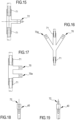
- Figure 18 and 19 show non-limiting and schematic embodiments of arterial or venous connectors whose free port 72 is of a female type ( figure 18 ) or of a male type ( figure 19 ). Luer connectors are preferably used. Being of the same connection type, the arterial connector 40 and the venous connector 41 cannot be directly connected together.
- At least one air separator such as a bubble trap 8 is present in the blood circuit 6, 7, and preferably on the blood return line (a further bubble trap may be provided in the withdrawal line, too); moreover, a safety clamp 9 of the apparatus is active on the blood return line, and it is usually placed downstream the bubble trap 8 and close to the venous connector 41.
- the safety clamp 9 may be controlled by a control unit 10 of the apparatus 1. It shall be noted that albeit an air separator and a safety clamp are optional elements, their presence is preferable.
- the apparatus further comprises a bubble sensor 8a, active in correspondence of a portion of the return line 7 between bubble trap 8 and safety clamp 9; the bubble sensor is connected to the control unit 10 and sends to the control unit signals in case one or more bubbles are detected; in such a case, the control unit may stop the treatment and cause closure of the clamp 9.
- a corresponding safety clamp of the apparatus (not represented) may be provided in correspondence of the blood withdrawal line 6. The safety clamp is active on the blood withdrawal line 6 immediately downstream the arterial connector 40.
- the blood flow through the blood lines is controlled by a blood pump 11, for instance a peristaltic blood pump, acting either on the blood withdrawal line or on the blood return line.
- the blood pump 11 is a peristaltic blood pump, part of the apparatus 1.
- An operator may enter a set value for the blood flow rate Q B through a user interface 12 (or the apparatus may calculate the blood flow rate based on other set parameters) and the control unit 10, during treatment, is configured to control the blood pump based on the set/calculated blood flow rate.
- the control unit is "configured” or "programmed” to execute certain steps: this may be achieved in practice by any means which allow configuring or programming the control unit.
- the apparatus 1 is provided with a (graphic) user interface which is configured to allow setting parameters for the treatment and to impart commands and controls to the apparatus 1 in the various operative configurations thereof.
- the user interface may comprise a screen or monitor, optionally touch sensitive, and one or more switches and/or pushbuttons specifically configured to cause a particular operation of the apparatus 1.
- the disposable circuit further comprise an effluent fluid line 13 connected, at one end, to an outlet of the secondary chamber 4 and, at the other end, to an effluent fluid container 14 collecting spent fluid extracted from the secondary chamber.
- the effluent line 13 may direct spent fluid directly to a drain.
- the effluent fluid line is configured to be interfaced with an effluent fluid pump 17 of the apparatus: the effluent fluid pump 17 operates on the effluent fluid line under the control of the control unit 10 to regulate the flow rate Q eff across the effluent fluid line.
- a dialysis fluid line 19 is connected at one end with a dialysis fluid container 20 (or to a dialysis fluid preparation device) and at its other end with the inlet of the secondary chamber 4 of the filtration unit.
- the dialysis fluid line 19 of the fluid circuit is configured to cooperate with a dialysis liquid pump 17a of the apparatus 1.
- the dialysis liquid pump 17a works on the dialysis liquid fluid line under the control of said control unit 10, to supply fresh dialysis fluid from the dialysis liquid container to the secondary chamber at a flow rate Q dial .
- disposable circuits may comprise the above mentioned effluent fluid line 13 and dialysis fluid line 19 as disposable components integrally fixed to the filtration unit. At the end of the treatment, the entire disposable set is disposed. The dialysis fluid line 19 received fresh fluid from container 20, the spent dialysis fluid is routed to the effluent bag 14.
- chronic renal treatment disposables include neither the dialysis fluid line nor the effluent fluid line as disposable parts.
- the dialysis fluid line and the effluent fluid line are non-disposable fluid paths arranged into the apparatus 1.
- a detachable connection is provided to removably place in fluid communication the dialysis fluid line and the effluent fluid line respectively to the inlet and the outlet of the secondary chamber 4 of the filtration unit; the latter being part of the disposable circuit.
- Dialysis fluid is either on-line prepared mixing water with concentrates, or received from a central dialysis fluid preparation plant.
- Effluent fluid pump 17 and dialysis pump 17a cooperate to force fluid flow from the dialysis fluid container 20 through the dialysis fluid line 19, to the dialysis pump 17a, then to the inlet of the secondary chamber 4 through the filter 2 up to the outlet of the secondary chamber 4, when fluid enters the effluent fluid line 13 to flow at the effluent fluid pump 17 and then to the effluent fluid container 14.
- the dialysis fluid pump 17a and the effluent fluid pump 17 are part of means for regulating the flow of fluid through the respective lines and, as mentioned, are operatively connected to the control unit 10 which controls the pumps.
- the control unit 10 is also connected to the user interface 12, for instance a graphic user interface, which receives operator's inputs and displays the apparatus outputs.
- the graphic user interface 12 may include a touch screen, a display screen and hard or soft keys for entering user's inputs or a combination thereof.
- the disposable circuit shown in figure 1 may include an infusion line 21 connected, at one end, with a portion 6a of the blood withdrawal line 6 positioned upstream the blood pump 11 and, at its other end, with an infusion fluid container 23, which for instance may contain a regional anticoagulant such as a citrate solution, or a replacement solution or other fluids.
- This infusion line is hereinafter referred to as pre-blood pump pre-dilution infusion line 21.
- the means for regulating the fluid flow comprises a pump 22, for instance a peristaltic pump controlled by control unit 10, acting on a segment of the pre-blood pump pre-dilution infusion line 21 to regulate a pre-blood pump infusion rate Q pbp .
- the pump 22 is part of the apparatus 1.
- the three way connector above described is a "non-disconnectable connector", that means that in the normal use the connector is not configured to be disconnected from any portion of conduit connected at any of its three ports or, equivalently, that the portion of conduits connected at any of its three ports are fixedly jointed thereto, e.g. through bonding or sealing.
- the embodiment of figure 1 also includes a post-blood pump pre-dilution fluid line 15 connected, at one end, directly with a portion 6a of the blood withdrawal line 6 positioned downstream the blood pump 11 and, at its other end, with a further infusion fluid container: this post-blood pump pre-dilution fluid line 15 supplies replacement fluid from an infusion fluid container 16 connected at one end of the post-blood pump pre-dilution fluid line 15.
- the apparatus further comprises an infusion pump 18, for instance a peristaltic pump, operating on the post-blood pump pre-dilution fluid line 15 to regulate the flow rate Q pre through the line 15.
- the apparatus of figure 1 may also present a post-dilution fluid line 25 connected at one end with a further container 26 of infusion liquid and connected at its other end with the blood return line 7.
- a further pump 27, for instance a peristaltic pump, may act under the control of control unit 10 on the post-dilution fluid line 25 and thus also be part of said means for regulating the flow through the fluid lines.
- the apparatus of figure 1 may comprise one or more auxiliary lines, which are connected, at one end, with the blood circuit, for example to the blood withdrawal line 6.
- Figure 1 shows a single auxiliary line 42.
- a further pump, not shown in figure 1 may act under the control of control circuit 10 on the auxiliary line and thus also be part of said means for regulating the flow through the fluid lines.
- the apparatus 1 may also comprise a first scale 33 operative for providing weight information relative to the amount of the spent fluid collected in the effluent fluid container 14; a second scale 34 operative for providing weight information relative to the amount of the fluid supplied from the infusion fluid container 16 via a post blood pump pre-dilution infusion line 15; a third scale 35 operative for providing weight information relative to the amount of the fluid supplied from dialysis fluid container 20.
- a respective scale 36 and 37 could be present to provide weight information relative to the amount of fluid supplied from infusion containers 23, 26.
- the scales are all connected to the control unit 10 and provide said weight information for the control unit 10 to determine the actual quantity of fluid in each container and/or the actual flow rate of fluid supplied by or received in each container.
- the control unit 10 may then be configured to receive treatment selection information and check if the user entered the required dialysis parameters.
- the control unit may also be configured to receive weight information from the first scale and, depending upon the selected treatment, from the scales associated to the container supplying the lines involved in the delivery of the selected treatment) and to control, at least at the beginning of the treatment, the flow rate of at least one of the effluent fluid, the infusion fluid, the dialysis fluid by controlling said means for regulating based on said weight information, and the initial set values.
- the containers 14, 16, 20, 23, 26 may be disposable plastic containers, preferably soft plastic bags which are hang on a support carried by the respective scale.
- the means for regulating flows typically comprises pumps, although other regulating means as valves or combinations of valves and pumps could be used.
- the scales may comprise piezoelectric sensors, or strain gauges, or spring sensors, or any other type of transducer able to sense forces applied thereon. Although the examples in the figures show use of scales for determining the amount of fluid in the respective containers and for allowing calculation of the respective flow rates through the various lines, it should be noted that the above described aspects of the invention are compatible also with blood treatment machines using volumetric sensors for determining flow rates or combinations of mass and volumetric sensors.
- Hemoperfusion is a method of filtering the blood extracorporeally to remove one or more toxins.
- the blood travels from the patient into a blood withdrawal line 6, gets filtered in a filtration unit 2, and then travels back into the patient through a blood return line 7, typically by using venovenous access.
- the blood perfuses a filter composed of artificial cells filled with activated carbon or another microporous material.
- no infusion line may be present.
- the first and second auxiliary connectors are placed on the blood line, for examples in the positions as below disclosed according to the fourth embodiment.
- a pre-blood pump pre-infusion line may be included for injecting a solution into the blood upstream the blood pump.
- the first and the second auxiliary connectors may be placed on the pre-blood pump pre-infusion line, or may remain on the blood circuit (or one connector may be placed on the pre-blood pump pre-infusion line and the other one may be placed on the blood line.
- the apparatus of embodiments may be (alternatively or in addition) an extracorporeal CO 2 Removal (ECCO2R) device; the blood line circuit may be connected to a CO 2 removal filtration unit 2 and the apparatus may or may not include any infusion lines.
- the first and second auxiliary connectors may be placed on the blood circuit in case no infusion line is available, or on either the blood circuit or the infusion line, if present.
- the disposable circuit of the present disclosure is designed to allow for temporary disconnection and then patient reconnection to the same disposable circuit to continue a (temporary) interrupted treatment.
- the disposable set is reconfigurable for allowing fluid (e.g., blood) recirculation mainly in the blood circuit.
- fluid e.g., blood
- recirculation configuration another configuration for the disposable circuit herewith described is here referred as "recirculation configuration”. In said configuration, the patient is disconnected from the disposable circuit and fluid therein present may be recirculated for allowing the patient to move away from the extracorporeal blood treatment apparatus.
- a patient may be temporarily disconnected from the apparatus 1 to perform or undergo other exams or treatments while the treatment performed with the apparatus 1 is suspended in a very easy way, without requesting expensive complete change of disposable circuit and with a reduced health risk in relation to the disconnection - recirculation - reconnection operations.
- no additional components are required to achieve temporary disconnection, such as additional 'Y' connector, saline bag, etc.
- An easy switching or reconfiguration capability between the operative configuration and the recirculation configuration further eases the activity of the qualified operators that help the patient throughout the performance of the treatment.
- the recirculation configuration i.e.
- the target means values of flow rate(s) and/or prescribed does is interrupted, average values that may have been calculated and/or measured by the control unit 10 or any of the sensors operatively connected thereto are preferably stored in a memory. Calculation and/or measurement thereof, starts back at the end of the temporary disconnection of the patient, when the control unit 10 is properly set for re-establishing the original operative configuration of blood treatment; optionally, albeit preferably, the control unit 10 may be configured to allow calculation and/or measurement of partial values before the instauration of the recirculation configuration and after the re-instauration of the operative configuration.
- a first and a second auxiliary connector which in the recirculation configuration are connected one with the venous connector 40 and the other with the arterial connector 41 for the purposes of defining a properly closed circuit allowing the fluid recirculation under the action of the blood pump 11.
- two auxiliary connectors are disclosed, in line of principle at least one auxiliary connector could be sufficient to make the closed circuit.
- the fluid inside the closed loop may then be recirculated.
- saline or other replacement fluid should be recirculated (i.e., not blood).
- the auxiliary connectors are three way connectors having a main inlet and a main outlet receiving pieces of the main line where they are placed and are provided with at least one disconnectable port which may be sealed through a cap or, alternatively, which may be of a self-sealing type.
- This latter type is such that the port automatically seals when another connector is disconnected from the disconnectable port of the auxiliary connector and automatically opens when the other connector is connected to the disconnectable port of the auxiliary connector.
- a self-sealing type auxiliary connector helps preventing unwanted fluid (in particular blood) leakage when the patient treatment is interrupted and the configuration of the disposable circuit is switched between the operative configuration and the recirculation configuration, reduces the risk of inclusion of air bubbles in the blood circuit and further eases the operations performed by the qualified operators that assist the patient.
- the auxiliary connector may have a wide variety of shapes, and may be provided with at least one first, or even with a second, disconnectable and free port which may be used to connect the auxiliary connector with another auxiliary connector and/or with the other one of the venous and the arterial connector.
- Non-limiting configurations of the connectors according to the present disclosure comprise three way auxiliary connectors like a "T" shaped connector ( figure 15 ).
- the illustrated connector (being it the first or the second auxiliary connector) comprises a first and a second non-disconnectable service port 71 fixed (e.g., sealed) to respective flexible tube portions.
- the tube portions may be respective tube portions of the pre-blood pump pre-dilution line 21; alternatively, the tube portions may be respective tube portions of any other infusion line or tube portions of the blood withdrawal or return line.
- the disconnectable port 72 represented only schematically may be a male (or female) Luer connector configured to couple with the corresponding female (or male) Luer connector 40, 41 of the blood withdrawal line 6 or of the blood return line 7.
- a "Y" shaped connector, a half-snowflake shaped connector or another connector of different geometry may be used.
- the first and second auxiliary connectors may be made in a single piece, wherein the first and the second non-disconnectable service port 71 are still fixed (e.g., sealed) to respective flexible tube portions, but the merged connector includes two disconnectable ports 70, 70a for receiving the withdrawal line connector 40 and the return line connector 41, respectively. Also in this design, if the withdrawal line connector 40 and the return line connector 41 are Luer male connectors, then the two disconnectable ports 70 are Luer female connectors and vice versa.
- the geometry of the 'integral' connector may also be different, such as the embodiment of figure 17 , wherein the two disconnectable ports 70 emerge parallel to each other on the same lateral side of the device.
- Figure 1 presents, in a single schematic diagram, principal and non-limiting embodiments conceived by the inventors that are further herewith described in detail.
- first auxiliary connector 53 and the second auxiliary connector 52 are arranged on the pre-blood pump pre-dilution infusion line 21, in a portion of conduit that once the disposable circuit is properly installed on the apparatus 1, lies downstream the pump 22 arranged on the pre-blood pump pre-dilution infusion line 21.
- the first auxiliary connector 53 is arranged downstream the second auxiliary connector 52.
- full flow rate (double arrow) is present in the blood withdrawal line 6 downstream the pre-blood pump pre-dilution infusion line 21 and in the blood return line 7; a full flow rate arrives to the second auxiliary connector 52 and there the flow rate is split into partial flow rates (single arrows) that are present in the portions of lines connecting the second auxiliary connector 52 to the first auxiliary connector 53 and then in the portion of line that connects the arterial connector 40 to the pre-blood pump pre-dilution infusion line 21 injection point in the blood withdrawal line 6.
- the two partial flow rates merges again generating a full flow rate.
- a double arrow indicates a full flow rate and its direction along the lines; a single arrow indicates a split (partial) flow rate and its direction along the line portion.
- the same representation is used in respect to all the figures showing recirculation.
- the first and the second auxiliary connectors are both three-way connectors which are provided each with a disconnectable port 70 configured to be connected to the disconnectable port 72 of one connector selected between the venous connector 40 and the arterial connector 41 in accordance to one of the two possible alternatives above identified.
- the disconnectable port 72 of the first and second auxiliary connectors 53, 52 are of a type which opposite to the type of the disconnectable port of the venous and arterial connectors. In other words, when the disconnectable port 72 of the first and second auxiliary connectors 53, 52 are of a male type, the disconnectable port of the arterial and venous connector is of a female type, and vice-versa.
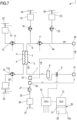
- first auxiliary connector 51 and the second auxiliary connector 50 are arranged on the post-blood pump pre-dilution infusion line 15, in a portion of conduit that once the disposable circuit is properly installed on the apparatus 1, lies downstream the pump 18 arranged on the post-blood pump pre-dilution infusion line 15.
- the first auxiliary connector 51 is arranged downstream the second auxiliary connector 50.
- full flow rate is present in the blood withdrawal line 6 upstream the post-blood pump pre-dilution infusion line 15 and, the full flow rate is split at the injection point of line 15 and partial flow rate is present in the blood return line 7, in the venous connector 41 up to the first auxiliary connector 51; here the partial flow coming up from the blood withdrawal line and the partial flow at the to the first auxiliary connector 50 merge and in the portion of line that connects the first auxiliary connector 51 to the second auxiliary connector 50 and up to the blood withdrawal line 6 there is full flow, as represented.
- the first and the second auxiliary connectors 50, 51 are both three-way connectors which are provided each with a disconnectable port 70 configured to be connected to another disconnectable port 72 of one connector selected between the venous connector 40, and the arterial connector 41 in accordance to one of the two possible alternatives above identified.
- the disconnectable port 72 of the first and second auxiliary connectors 51, 50 are of a type which opposite to the type of the disconnectable port of the venous and arterial connectors. In other words, when the disconnectable port 72 of the first and second auxiliary connectors 51, 50 are of a male type, the disconnectable port of the arterial and venous connector is of a female type, and vice-versa.
- the post-blood pump pre-dilution infusion line 15 may comprise a pressure drop valve or flow resistor 60, which is in particular and in a non-limiting extent installed downstream the first auxiliary connector 51, just upstream the non-disconnectable three way connector that connects the post-blood pump pre-dilution infusion line 15 to the blood withdrawal line 6.
- the pressure drop valve or flow resistor 60 is configured to even flow resistances during recirculation and may be detachable or fixedly installed on the fluid line; optionally, the drop valve or flow resistor may be of a variable-resistance type.
- the aim of the drop valve or flow resistor 60 is to make the resistances of the respective portions of the pipe similar so that the flows generated in each of the circuit branches are as similar as possible.
- first auxiliary connector 57 and the second auxiliary connector 56 are arranged on the post-dilution fluid line 25, in a portion of conduit that once the disposable circuit is properly installed on the apparatus 1, lies downstream the pump 27 arranged on the post-dilution fluid line 25.
- the first auxiliary connector 57 is arranged downstream the second auxiliary connector 56.
- full flow rate is present in the blood withdrawal line 6 and in the portion of blood return line 7 that departs from the outlet of the primary chamber 3 and arrives to the non-disconnectable connector which connects the blood return line 7 to the post-dilution fluid line 25; partial flow rate is present in the portions of lines connecting the first auxiliary connector 57 to the second auxiliary connector 56 and then in the portion of the blood return line 7 downstream the post-dilution fluid line 25.
- the first and the second auxiliary connectors are both three-way connectors which are provided each with a disconnectable port 70 configured to be connected to another disconnectable port 72 of one connector selected between the venous connector 40, the arterial connector 41 in accordance to one of the two possible alternatives above identified.
- the disconnectable port 72 of the first and second auxiliary connectors 57, 56 are of a type which opposite to the type of the disconnectable port of the venous and arterial connectors. In other words, when the disconnectable port 72 of the first and second auxiliary connectors 57, 56 are of a male type, the disconnectable port of the arterial and venous connector is of a female type, and vice-versa.
- the post-dilution fluid line 25 may comprise a pressure drop valve or flow resistor 60, which is in particular installed downstream the first auxiliary connector 57 just upstream the non-disconnectable three way connector that connects the post-dilution fluid line 25 to the blood return line 7.
- the pressure drop valve or flow resistor 60 is configured to even flow resistances during recirculation and may be detachable or fixedly installed on the fluid line; optionally, the drop valve or flow resistor may be of a variable-resistance type.
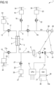
- the first auxiliary connector 59 and the second auxiliary connector 58 are arranged both on the blood circuit, being configured so that the first auxiliary connector 59 is arranged on the blood return line 7 while the second auxiliary connector 58 is arranged on the blood withdrawal line 6.
- the second auxiliary connector 58 lies on the portion 6a of the blood withdrawal line 6 that once the disposable circuit is properly installed on the apparatus 1, lies upstream the blood pump 11; the first auxiliary connector 59 is preferably installed upstream the bubble detector 8a and the safety clamp 9. Therefore, the first auxiliary connector 59 is arranged downstream the second auxiliary connector 58.
- the first auxiliary connector 59 is connected to the arterial connector 40 and the second auxiliary connector 58 is connected to the venous connector.
- full flow rate is present in the blood withdrawal line 6 downstream the second auxiliary connector 58 and upstream the first auxiliary connector 59, i.e. in the respective portions of blood withdrawal lines 6 between the second auxiliary connector 58 and the inlet of the primary chamber 3, and in the portion of blood return line 7 between the outlet of the primary chamber and the first auxiliary connector 59; partial flow rate is present in the portions of blood withdrawal line 6 that lies between the second auxiliary connector 58 and the arterial connector 40 and in the blood return line 7 that lies between the first auxiliary connector 59 and the venous connector 41.
- the first and the second auxiliary connectors are both three-way connectors which are provided each with a disconnectable port 70 configured to be connected to another disconnectable port 72 of one connector selected between the venous connector 40, the arterial connector 41.
- the disconnectable port 72 of the first and second auxiliary connectors 59, 58 are of a type which opposite to the type of the disconnectable port of the venous and arterial connectors. In other words, when the disconnectable port 72 of the first and second auxiliary connectors 59, 58 are of a male type, the disconnectable port of the arterial and venous connector is of a female type, and vice-versa.
- Figure 11 shows an alternative connection wherein the first and the second auxiliary connectors are both placed on the blood withdrawal line 6, in the line portion 6a upstream the blood pump 11; the venous connector 41 is connected directly to the second auxiliary connector 58; the arterial connector 40 is connected directly to the first auxiliary connector 59 which is placed downstream the second auxiliary connector 58. It may be noted that this latter configuration is not to be considered as preferred but anyway still allowable to define a closed circuit allowing fluid recirculation as intended in the present disclosure.
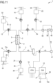
- the first auxiliary connector 55 and the second auxiliary connector 54 are arranged both on a single auxiliary line which is installed in a portion of e.g., the blood withdrawal line 6, preferably but in a non-limiting extent, in a portion of the blood withdrawal line that once the disposable circuit is properly arranged on the apparatus 1 lies upstream the blood pump 11.
- the first auxiliary connector 55 is arranged downstream the second auxiliary connector 54.
- full flow rate is present in the blood withdrawal line 6 downstream the auxiliary line 42 and in the blood return line 7; partial flow rate is present in the auxiliary line 42 and in the portion of blood withdrawal line 6 which is comprised between the three way non-disconnectable connector which connects one end of the auxiliary line 42 with the blood withdrawal line 6 and the second end of the blood withdrawal line 6 which ends on the arterial connector 40.
- one connector between the first and the second auxiliary connectors is a three-way connector which is provided with a disconnectable port 70 configured to be connected to another disconnectable port 72 of one connector selected between the venous connector 40, the arterial connector 41 in accordance to one of the two possible alternatives above identified.
- the other connector is a two way connector provided with a disconnectable port and a non-disconnectable port fixedly installed on a respective tube portion of the auxiliary line 42.
- the disconnectable port 72 of the first and second auxiliary connectors 55, 54 are of a type which opposite to the type of the disconnectable port of the venous and arterial connectors. In other words, when the disconnectable port 72 of the first and second auxiliary connectors 55, 54 are of a male type, the disconnectable port of the arterial and venous connector is of a female type, and vice-versa.
- the fifth embodiment is similar to the first embodiment; however, a service line 42 instead of a treatment line 21 is used for the temporary disconnection and recirculation.
- a sixth embodiment of the disposable circuit is schematically shown in figure 14 ; it is provided with a first auxiliary line 42 and a second auxiliary line 42a arranged on a portion of the blood withdrawal line 6 which - preferably albeit in a non-limiting extent - when the disposable circuit is properly arranged on the apparatus 1 lie both upstream the blood pump 11 and optionally upstream the pre-blood pump pre-infusion line 21.
- Each of the first and second auxiliary lines 42, 42a are provided with a first end connected to the blood withdrawal line 6 and a second end which terminates on a respective first auxiliary connector 55 arranged on the first auxiliary line 42 and a second auxiliary connector 54 arranged on the second auxiliary line 42a.
- full flow rate is present in the blood withdrawal line 6 downstream the second auxiliary line 42a and in the blood return line 7; partial flow rate is present in the first, second auxiliary lines 42, 42a and in the portion of blood withdrawal line 6 which is comprised between the three way non-disconnectable connector which connects one end of the first auxiliary line 42 with the three way non-disconnectable connector which connects one end of the second auxiliary line 42a upstream up to the second end where the blood withdrawal line 6 ends with the arterial connector 40.
- both the first and the second auxiliary connectors are two way connectors provided with a disconnectable port and a non-disconnectable port fixedly installed on a respective tube portion of the respective first, second auxiliary line 42.
- the disconnectable port 72 of the first and second auxiliary connectors 55, 54 are of a type which opposite to the type of the disconnectable port of the venous and arterial connectors. In other words, when the disconnectable port 72 of the first and second auxiliary connectors 55, 54 are of a male type, the disconnectable port of the arterial and venous connector is of a female type, and vice-versa.
- first and second auxiliary connectors may be placed one on any of the described infusion lines and the other on the blood circuit, properly allowing for blood recirculation when connected to the arterial and venous connectors 40, 41.
- the disposable circuit In use, before starting with the treatment configuration, the disposable circuit is installed on the apparatus 1; for easing the installation of the disposable circuit, and as well for reducing the risk of errors performed by the qualified operators during said installation, the apparatus 1 may be provided with visual instructions on the GUI helping the operator in the correct placement.
- the control unit 10 provides on a screen of the user interface of the apparatus 1 selection items for the machine configuration before the treatment. Once prescription and the relevant parameters are entered, the disposable circuit is properly primed; thereafter, the blood circuit is connected to the patient vascular access and the treatment is started.
- the user interface has a corresponding screen, wherein a selection item, for instance an icon, for the recirculation configuration may be user selected.
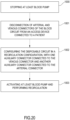
- the control unit 10 configures the apparatus 1 in a particular configuration wherein first at least the blood pump 11 and preferably all the pumps of the apparatus 1 are stopped (block 1000). Stopping of at least the blood pump 11 is required for switching or reconfiguring the apparatus 1 to the aforementioned recirculation configuration, and thus the disposable circuit from the treatment configuration to the recirculation configuration and vice-versa, since the blood pump 11 is the pump mainly involved in forcing fluid circulation from the arterial connector to the venous connector in both the operative and in the recirculation configuration.
- the stopping signal may be sent also to the effluent fluid pump 17 and the dialysis pump 17a.
- dialysis fluid continues circulating in the fluid circuit, at least the ultrafiltration is stopped or set to a minimum very low value.
- one or more infusion pumps may run, and the infused fluid be balanced by ultrafiltration.
- a disconnection of the patient from the apparatus 1 takes place: the user (and/or the apparatus) clamps the blood line ends and then disconnect the arterial connector 40 and venous connector 41 from the access device (e.g., the central catheter or the access needles), so that the arterial connector and the venous connector 40, 41 result both with a respective disconnectable end actually free, ready to be connected to the respective free end of the auxiliary connectors, according to one of the aforementioned embodiments.
- the access device e.g., the central catheter or the access needles
- the first auxiliary connector and the second auxiliary connector are then connected to the venous connector 41 and to the arterial connector 40, preferably according to the disclosure of any of the configurations of the embodiments described before.
- the first auxiliary connector and the second auxiliary connectors are of a self-sealing type, there is typically no need for the operator to remove closing caps from the disconnectable ports 70, 70a of the auxiliary connectors; otherwise, before properly setting the connection of the auxiliary connectors to the respective arterial connector 40 and venous connector 41, the operator shall properly remove any protective and/or closing cap from the disconnectable port.
- the self-sealing connector has no cap, there may be a need to clean/disinfect the self-sealing port before making a connection to it.
- the portions of the blood circuit 6, 7 closer to both the arterial connector 40 and venous connector 41 may be the ones which are the more easily accessible and/or free or anyway distant from a position at least temporarily defined on pathways on the apparatus 1: therefore, the step of reciprocal connection of an auxiliary connector with either a venous connector 40 or an arterial connector 41 may be preferably performed by moving a portion of the blood circuit 6, 7, so that is physically the venous connector (or the arterial connector) to be brought first closer and then in contact with the free end port of the respective auxiliary connector.
- the blood lines are unclamped and the operator shall promptly intervene on the user interface of the apparatus 1 to set a command of reactivation of at least the blood pump 11.
- This step is schematically indicated in block 1003 of figure 24. Preferably this is made through an interaction with a specific icon provided on a screen of the apparatus 1, or through the action on a specific activation button on the apparatus 1 (block 1003, figure 24).
- any pump of a fluid line connected to the blood circuit 6, 7 is, and rests, deactivated for the entire process of recirculation. This is particularly suitable when the first auxiliary connector and the second auxiliary connector are arranged both downstream the pumps of the fluid lines, because stopping of the pump acts as a means for impeding free fluid circulation in the respective fluid line upstream the pump.
- the user selects a specific command on the user interface operatively connected to control unit 10 which stops the activation of the blood pump 11, and if the effluent fluid pump 17 and the dialysis pump 17a were left active during the recirculation of fluid, also those pumps may be stopped. Then the operator clamps and disconnects the venous connector 40 and arterial connector 41 from the respective first auxiliary connector, second auxiliary connector at which they are connected. The closed configuration for the circuit defined when the recirculation configuration of the disposable circuit was started is then ended, and temporarily the disposable circuit is open.
- first auxiliary connector and the second auxiliary connector are not of a self-sealing type, the operator then provides to close the free disconnectable end thereof; otherwise, if the first auxiliary connector and the second auxiliary connector are of a self-sealing type, this latter action of the operator is not required.
- the venous connector 40 and arterial connector 41 are then reconnected to the access device of the patient and unclamped; through the menu of the control unit 10 on the screen, the user selects the selection item corresponding to the restart of the blood treatment, and pumps of the apparatus 1, in particular at least the blood pump 11, is then reactivated. Reactivation is preferably made also for the effluent fluid pump 17 and the dialysis pump 17a, and for all infusion pumps (as required by the set treatment mode) for allowing treatment delivery.
- extracorporeal blood may be restituted to the patient before recirculation.
- the arterial connector 40 is disconnected from the access device of the patient and is connected to a bag containing physiological fluid (e.g., saline or replacement fluid).
- physiological fluid e.g., saline or replacement fluid.
- the blood withdrawal line is unclamped and blood pump reactivated to return blood to the patient via the blood return line which is still connected to the vascular access.
- blood withdrawal line is clamped and the arterial connector is properly connected to the first or the second auxiliary connector.
- the blood return line is clamped, the venous connector 41 removed from the access device and connected to the other one of the first and second auxiliary connector.
- the user unclamps the blood lines and starts recirculation of the physiological fluid inside the recirculation circuit.
- the content of the bag feeding the infusion line may be used to provide a suitable fluid for restituting blood.
- the blood withdrawal line is clamped and the infusion pump (and if necessary the blood pump, too) is activated to force fluid to enter into the blood lines and push blood to the patient via the blood return line and vascular access.
- This alternative procedure may be performed even before disconnecting the arterial connector.
- the usual alarms such as the access, arterial and venous pressure alarms are deactivated or the alarm windows changed. Indeed, the different conditions during recirculation is not compatible with the usual alarm thresholds and with no change/deactivation would generate several false alarms.
- Parts of the process therein described may be provided through a data processing unit, technically interchangeable with one or more data processing units conceived for executing a portion of a software program or a firmware program loaded to a memory support.
- the software or firmware program may be written in any known programming language.
- the electronic computers if two or more, may be connected each other through a data connection such that the computation powers thereof may be shared; the electronic computers may therefore be installed in different positions thereby realizing the data connection in a distributed computing environment.
- the data processing unit, or control unit may be a general purpose processor, specifically configured for executing one or more parts of the process defined in the present disclosure through the software or firmware program, or may be an ASIC or a dedicated processor or an FPGA, specifically programmed for executing at least part of the operations of the process herein described.
- the memory support may be located inside or outside the processor or control unit or data processing unit, and may be geographically remotely located therefrom.
Landscapes
- Health & Medical Sciences (AREA)
- Heart & Thoracic Surgery (AREA)
- Vascular Medicine (AREA)
- Biomedical Technology (AREA)
- Engineering & Computer Science (AREA)
- Anesthesiology (AREA)
- Hematology (AREA)
- Life Sciences & Earth Sciences (AREA)
- Animal Behavior & Ethology (AREA)
- General Health & Medical Sciences (AREA)
- Public Health (AREA)
- Veterinary Medicine (AREA)
- Cardiology (AREA)
- Pulmonology (AREA)
- External Artificial Organs (AREA)
Priority Applications (7)
| Application Number | Priority Date | Filing Date | Title |
|---|---|---|---|
| EP20306706.1A EP4023271B1 (en) | 2020-12-29 | 2020-12-29 | Disposable circuit for extracorporeal treatment of blood, apparatus for extracorporeal treatment of blood and associated method |
| PL20306706.1T PL4023271T3 (pl) | 2020-12-29 | 2020-12-29 | Jednorazowy obwód do pozaustrojowego oczyszczania krwi, aparat do pozaustrojowego oczyszczania krwi i powiązany sposób |
| ES20306706T ES2996859T3 (en) | 2020-12-29 | 2020-12-29 | Disposable circuit for extracorporeal treatment of blood, apparatus for extracorporeal treatment of blood and associated method |
| PCT/EP2021/078070 WO2022144117A1 (en) | 2020-12-29 | 2021-10-11 | Disposable circuit for extracorporeal treatment of blood, apparatus for extracorporeal treatment of blood and associated method |
| JP2023538095A JP7763840B2 (ja) | 2020-12-29 | 2021-10-11 | 血液の体外処理のための使い捨て回路、血液の体外処理のための装置、および、関連する方法 |
| CN202180094865.7A CN116916982A (zh) | 2020-12-29 | 2021-10-11 | 用于血液体外处理的一次性回路,用于血液体外处理的装置和相关联的方法 |
| US18/270,122 US20240058519A1 (en) | 2020-12-29 | 2021-10-11 | Disposable circuit for extracorporeal treatment of blood, apparatus for extracorporeal treatment of blood and associated method |
Applications Claiming Priority (1)
| Application Number | Priority Date | Filing Date | Title |
|---|---|---|---|
| EP20306706.1A EP4023271B1 (en) | 2020-12-29 | 2020-12-29 | Disposable circuit for extracorporeal treatment of blood, apparatus for extracorporeal treatment of blood and associated method |
Publications (2)
| Publication Number | Publication Date |
|---|---|
| EP4023271A1 EP4023271A1 (en) | 2022-07-06 |
| EP4023271B1 true EP4023271B1 (en) | 2024-09-11 |
Family
ID=74191517
Family Applications (1)
| Application Number | Title | Priority Date | Filing Date |
|---|---|---|---|
| EP20306706.1A Active EP4023271B1 (en) | 2020-12-29 | 2020-12-29 | Disposable circuit for extracorporeal treatment of blood, apparatus for extracorporeal treatment of blood and associated method |
Country Status (7)
| Country | Link |
|---|---|
| US (1) | US20240058519A1 (pl) |
| EP (1) | EP4023271B1 (pl) |
| JP (1) | JP7763840B2 (pl) |
| CN (1) | CN116916982A (pl) |
| ES (1) | ES2996859T3 (pl) |
| PL (1) | PL4023271T3 (pl) |
| WO (1) | WO2022144117A1 (pl) |
Families Citing this family (1)
| Publication number | Priority date | Publication date | Assignee | Title |
|---|---|---|---|---|
| DE102020132472A1 (de) * | 2020-12-07 | 2022-06-09 | Fresenius Medical Care Deutschland Gmbh | Membrangasaustauscher |
Citations (1)
| Publication number | Priority date | Publication date | Assignee | Title |
|---|---|---|---|---|
| US5895368A (en) * | 1996-09-23 | 1999-04-20 | Medisystems Technology Corporation | Blood set priming method and apparatus |
Family Cites Families (6)
| Publication number | Priority date | Publication date | Assignee | Title |
|---|---|---|---|---|
| US5630946A (en) * | 1995-02-15 | 1997-05-20 | Pall Corporation | Method for processing a biological fluid including leukocyte removal in an extracorporeal circuit |
| US6561997B1 (en) | 1999-04-23 | 2003-05-13 | The Regents Of The University Of Michigan | Extracorporeal fluid circuit and related methods |
| US6649063B2 (en) * | 2001-07-12 | 2003-11-18 | Nxstage Medical, Inc. | Method for performing renal replacement therapy including producing sterile replacement fluid in a renal replacement therapy unit |
| SE0202172L (sv) * | 2002-02-25 | 2003-08-26 | Jostra Ab | Anordning och metod för cirkulatorisk isolering och behandling av kroppsdel |
| US7935258B2 (en) * | 2005-09-15 | 2011-05-03 | Gambro Lundia Ab | Process and an apparatus for filling and/or rinsing an extracorporeal blood circuit |
| US9713670B2 (en) | 2009-11-24 | 2017-07-25 | Fresenius Medical Care Deutschland Gmbh | Method for temporarily interrupting an extracorporeal blood treatment, control device and blood treatment apparatus |
-
2020
- 2020-12-29 PL PL20306706.1T patent/PL4023271T3/pl unknown
- 2020-12-29 ES ES20306706T patent/ES2996859T3/es active Active
- 2020-12-29 EP EP20306706.1A patent/EP4023271B1/en active Active
-
2021
- 2021-10-11 JP JP2023538095A patent/JP7763840B2/ja active Active
- 2021-10-11 WO PCT/EP2021/078070 patent/WO2022144117A1/en not_active Ceased
- 2021-10-11 US US18/270,122 patent/US20240058519A1/en active Pending
- 2021-10-11 CN CN202180094865.7A patent/CN116916982A/zh active Pending
Patent Citations (1)
| Publication number | Priority date | Publication date | Assignee | Title |
|---|---|---|---|---|
| US5895368A (en) * | 1996-09-23 | 1999-04-20 | Medisystems Technology Corporation | Blood set priming method and apparatus |
Also Published As
| Publication number | Publication date |
|---|---|
| PL4023271T3 (pl) | 2025-02-10 |
| JP7763840B2 (ja) | 2025-11-04 |
| JP2024500172A (ja) | 2024-01-04 |
| WO2022144117A1 (en) | 2022-07-07 |
| US20240058519A1 (en) | 2024-02-22 |
| EP4023271A1 (en) | 2022-07-06 |
| ES2996859T3 (en) | 2025-02-13 |
| CN116916982A (zh) | 2023-10-20 |
Similar Documents
| Publication | Publication Date | Title |
|---|---|---|
| EP2404629B1 (en) | Apparatus for controlling an extra-corporeal blood treatment in a medical device | |
| EP1590017B2 (en) | Extracorporeal blood treatment machine. | |
| AU2024204207B2 (en) | Apparatus for extracorporeal blood treatment | |
| EP2571546B1 (en) | User interface and machine | |
| US7314554B2 (en) | Extracorporeal blood treatment machine | |
| CA2762300C (en) | Method and system for providing priming and restitution liquids for an extracorporeal blood treatment | |
| EP4023271B1 (en) | Disposable circuit for extracorporeal treatment of blood, apparatus for extracorporeal treatment of blood and associated method | |
| US20250032693A1 (en) | Blood Treatment Apparatus With A Coupled Blood Pump And Compressed Pressure Device | |
| EP4072614B1 (en) | Fluid diverting device for an apparatus for extracorporeal treatment of blood and blood set provided with said fluid diverting device | |
| EP4194023A1 (en) | Disposable set and extracorporeal blood treatment apparatus for preventing degassing in an infusion fluid line |
Legal Events
| Date | Code | Title | Description |
|---|---|---|---|
| PUAI | Public reference made under article 153(3) epc to a published international application that has entered the european phase |
Free format text: ORIGINAL CODE: 0009012 |
|
| STAA | Information on the status of an ep patent application or granted ep patent |
Free format text: STATUS: THE APPLICATION HAS BEEN PUBLISHED |
|
| AK | Designated contracting states |
Kind code of ref document: A1 Designated state(s): AL AT BE BG CH CY CZ DE DK EE ES FI FR GB GR HR HU IE IS IT LI LT LU LV MC MK MT NL NO PL PT RO RS SE SI SK SM TR |
|
| STAA | Information on the status of an ep patent application or granted ep patent |
Free format text: STATUS: REQUEST FOR EXAMINATION WAS MADE |
|
| 17P | Request for examination filed |
Effective date: 20221227 |
|
| RBV | Designated contracting states (corrected) |
Designated state(s): AL AT BE BG CH CY CZ DE DK EE ES FI FR GB GR HR HU IE IS IT LI LT LU LV MC MK MT NL NO PL PT RO RS SE SI SK SM TR |
|
| REG | Reference to a national code |
Ref country code: DE Ref legal event code: R079 Free format text: PREVIOUS MAIN CLASS: A61M0001360000 Ipc: A61M0039100000 Ref document number: 602020037475 Country of ref document: DE |
|
| GRAP | Despatch of communication of intention to grant a patent |
Free format text: ORIGINAL CODE: EPIDOSNIGR1 |
|
| STAA | Information on the status of an ep patent application or granted ep patent |
Free format text: STATUS: GRANT OF PATENT IS INTENDED |
|
| RIC1 | Information provided on ipc code assigned before grant |
Ipc: A61M 1/36 20060101ALI20240422BHEP Ipc: A61M 39/10 20060101AFI20240422BHEP |
|
| INTG | Intention to grant announced |
Effective date: 20240514 |
|
| GRAS | Grant fee paid |
Free format text: ORIGINAL CODE: EPIDOSNIGR3 |
|
| GRAA | (expected) grant |
Free format text: ORIGINAL CODE: 0009210 |
|
| STAA | Information on the status of an ep patent application or granted ep patent |
Free format text: STATUS: THE PATENT HAS BEEN GRANTED |
|
| AK | Designated contracting states |
Kind code of ref document: B1 Designated state(s): AL AT BE BG CH CY CZ DE DK EE ES FI FR GB GR HR HU IE IS IT LI LT LU LV MC MK MT NL NO PL PT RO RS SE SI SK SM TR |
|
| REG | Reference to a national code |
Ref country code: GB Ref legal event code: FG4D |
|
| REG | Reference to a national code |
Ref country code: CH Ref legal event code: EP |
|
| REG | Reference to a national code |
Ref country code: DE Ref legal event code: R096 Ref document number: 602020037475 Country of ref document: DE |
|
| REG | Reference to a national code |
Ref country code: IE Ref legal event code: FG4D |
|
| REG | Reference to a national code |
Ref country code: SE Ref legal event code: TRGR |
|
| PGFP | Annual fee paid to national office [announced via postgrant information from national office to epo] |
Ref country code: DE Payment date: 20241121 Year of fee payment: 5 |
|
| REG | Reference to a national code |
Ref country code: LT Ref legal event code: MG9D |
|
| PG25 | Lapsed in a contracting state [announced via postgrant information from national office to epo] |
Ref country code: NO Free format text: LAPSE BECAUSE OF FAILURE TO SUBMIT A TRANSLATION OF THE DESCRIPTION OR TO PAY THE FEE WITHIN THE PRESCRIBED TIME-LIMIT Effective date: 20241211 |
|
| REG | Reference to a national code |
Ref country code: NL Ref legal event code: MP Effective date: 20240911 |
|
| PG25 | Lapsed in a contracting state [announced via postgrant information from national office to epo] |
Ref country code: GR Free format text: LAPSE BECAUSE OF FAILURE TO SUBMIT A TRANSLATION OF THE DESCRIPTION OR TO PAY THE FEE WITHIN THE PRESCRIBED TIME-LIMIT Effective date: 20241212 Ref country code: FI Free format text: LAPSE BECAUSE OF FAILURE TO SUBMIT A TRANSLATION OF THE DESCRIPTION OR TO PAY THE FEE WITHIN THE PRESCRIBED TIME-LIMIT Effective date: 20240911 |
|
| PGFP | Annual fee paid to national office [announced via postgrant information from national office to epo] |
Ref country code: GB Payment date: 20241122 Year of fee payment: 5 |
|
| PG25 | Lapsed in a contracting state [announced via postgrant information from national office to epo] |
Ref country code: BG Free format text: LAPSE BECAUSE OF FAILURE TO SUBMIT A TRANSLATION OF THE DESCRIPTION OR TO PAY THE FEE WITHIN THE PRESCRIBED TIME-LIMIT Effective date: 20240911 |
|
| PGFP | Annual fee paid to national office [announced via postgrant information from national office to epo] |
Ref country code: FR Payment date: 20241121 Year of fee payment: 5 |
|
| PG25 | Lapsed in a contracting state [announced via postgrant information from national office to epo] |
Ref country code: LV Free format text: LAPSE BECAUSE OF FAILURE TO SUBMIT A TRANSLATION OF THE DESCRIPTION OR TO PAY THE FEE WITHIN THE PRESCRIBED TIME-LIMIT Effective date: 20240911 |
|
| PG25 | Lapsed in a contracting state [announced via postgrant information from national office to epo] |
Ref country code: HR Free format text: LAPSE BECAUSE OF FAILURE TO SUBMIT A TRANSLATION OF THE DESCRIPTION OR TO PAY THE FEE WITHIN THE PRESCRIBED TIME-LIMIT Effective date: 20240911 |
|
| PG25 | Lapsed in a contracting state [announced via postgrant information from national office to epo] |
Ref country code: RS Free format text: LAPSE BECAUSE OF FAILURE TO SUBMIT A TRANSLATION OF THE DESCRIPTION OR TO PAY THE FEE WITHIN THE PRESCRIBED TIME-LIMIT Effective date: 20241211 |
|
| PGFP | Annual fee paid to national office [announced via postgrant information from national office to epo] |
Ref country code: IT Payment date: 20241218 Year of fee payment: 5 |
|
| PGFP | Annual fee paid to national office [announced via postgrant information from national office to epo] |
Ref country code: SE Payment date: 20241121 Year of fee payment: 5 |
|
| PG25 | Lapsed in a contracting state [announced via postgrant information from national office to epo] |
Ref country code: RS Free format text: LAPSE BECAUSE OF FAILURE TO SUBMIT A TRANSLATION OF THE DESCRIPTION OR TO PAY THE FEE WITHIN THE PRESCRIBED TIME-LIMIT Effective date: 20241211 Ref country code: NO Free format text: LAPSE BECAUSE OF FAILURE TO SUBMIT A TRANSLATION OF THE DESCRIPTION OR TO PAY THE FEE WITHIN THE PRESCRIBED TIME-LIMIT Effective date: 20241211 Ref country code: LV Free format text: LAPSE BECAUSE OF FAILURE TO SUBMIT A TRANSLATION OF THE DESCRIPTION OR TO PAY THE FEE WITHIN THE PRESCRIBED TIME-LIMIT Effective date: 20240911 Ref country code: HR Free format text: LAPSE BECAUSE OF FAILURE TO SUBMIT A TRANSLATION OF THE DESCRIPTION OR TO PAY THE FEE WITHIN THE PRESCRIBED TIME-LIMIT Effective date: 20240911 Ref country code: GR Free format text: LAPSE BECAUSE OF FAILURE TO SUBMIT A TRANSLATION OF THE DESCRIPTION OR TO PAY THE FEE WITHIN THE PRESCRIBED TIME-LIMIT Effective date: 20241212 Ref country code: FI Free format text: LAPSE BECAUSE OF FAILURE TO SUBMIT A TRANSLATION OF THE DESCRIPTION OR TO PAY THE FEE WITHIN THE PRESCRIBED TIME-LIMIT Effective date: 20240911 Ref country code: BG Free format text: LAPSE BECAUSE OF FAILURE TO SUBMIT A TRANSLATION OF THE DESCRIPTION OR TO PAY THE FEE WITHIN THE PRESCRIBED TIME-LIMIT Effective date: 20240911 |
|
| REG | Reference to a national code |
Ref country code: ES Ref legal event code: FG2A Ref document number: 2996859 Country of ref document: ES Kind code of ref document: T3 Effective date: 20250213 |
|
| REG | Reference to a national code |
Ref country code: AT Ref legal event code: MK05 Ref document number: 1722154 Country of ref document: AT Kind code of ref document: T Effective date: 20240911 |
|
| PG25 | Lapsed in a contracting state [announced via postgrant information from national office to epo] |
Ref country code: NL Free format text: LAPSE BECAUSE OF FAILURE TO SUBMIT A TRANSLATION OF THE DESCRIPTION OR TO PAY THE FEE WITHIN THE PRESCRIBED TIME-LIMIT Effective date: 20240911 |
|
| PG25 | Lapsed in a contracting state [announced via postgrant information from national office to epo] |
Ref country code: PT Free format text: LAPSE BECAUSE OF FAILURE TO SUBMIT A TRANSLATION OF THE DESCRIPTION OR TO PAY THE FEE WITHIN THE PRESCRIBED TIME-LIMIT Effective date: 20250113 Ref country code: IS Free format text: LAPSE BECAUSE OF FAILURE TO SUBMIT A TRANSLATION OF THE DESCRIPTION OR TO PAY THE FEE WITHIN THE PRESCRIBED TIME-LIMIT Effective date: 20250111 |
|
| PG25 | Lapsed in a contracting state [announced via postgrant information from national office to epo] |
Ref country code: SM Free format text: LAPSE BECAUSE OF FAILURE TO SUBMIT A TRANSLATION OF THE DESCRIPTION OR TO PAY THE FEE WITHIN THE PRESCRIBED TIME-LIMIT Effective date: 20240911 Ref country code: RO Free format text: LAPSE BECAUSE OF FAILURE TO SUBMIT A TRANSLATION OF THE DESCRIPTION OR TO PAY THE FEE WITHIN THE PRESCRIBED TIME-LIMIT Effective date: 20240911 |
|
| PGFP | Annual fee paid to national office [announced via postgrant information from national office to epo] |
Ref country code: ES Payment date: 20250102 Year of fee payment: 5 |
|
| PG25 | Lapsed in a contracting state [announced via postgrant information from national office to epo] |
Ref country code: AT Free format text: LAPSE BECAUSE OF FAILURE TO SUBMIT A TRANSLATION OF THE DESCRIPTION OR TO PAY THE FEE WITHIN THE PRESCRIBED TIME-LIMIT Effective date: 20240911 Ref country code: EE Free format text: LAPSE BECAUSE OF FAILURE TO SUBMIT A TRANSLATION OF THE DESCRIPTION OR TO PAY THE FEE WITHIN THE PRESCRIBED TIME-LIMIT Effective date: 20240911 |
|
| PG25 | Lapsed in a contracting state [announced via postgrant information from national office to epo] |
Ref country code: CZ Free format text: LAPSE BECAUSE OF FAILURE TO SUBMIT A TRANSLATION OF THE DESCRIPTION OR TO PAY THE FEE WITHIN THE PRESCRIBED TIME-LIMIT Effective date: 20240911 |
|
| PGFP | Annual fee paid to national office [announced via postgrant information from national office to epo] |
Ref country code: PL Payment date: 20241122 Year of fee payment: 5 |
|
| PG25 | Lapsed in a contracting state [announced via postgrant information from national office to epo] |
Ref country code: SK Free format text: LAPSE BECAUSE OF FAILURE TO SUBMIT A TRANSLATION OF THE DESCRIPTION OR TO PAY THE FEE WITHIN THE PRESCRIBED TIME-LIMIT Effective date: 20240911 |
|
| REG | Reference to a national code |
Ref country code: DE Ref legal event code: R097 Ref document number: 602020037475 Country of ref document: DE |
|
| PG25 | Lapsed in a contracting state [announced via postgrant information from national office to epo] |
Ref country code: MC Free format text: LAPSE BECAUSE OF FAILURE TO SUBMIT A TRANSLATION OF THE DESCRIPTION OR TO PAY THE FEE WITHIN THE PRESCRIBED TIME-LIMIT Effective date: 20240911 |
|
| PG25 | Lapsed in a contracting state [announced via postgrant information from national office to epo] |
Ref country code: DK Free format text: LAPSE BECAUSE OF FAILURE TO SUBMIT A TRANSLATION OF THE DESCRIPTION OR TO PAY THE FEE WITHIN THE PRESCRIBED TIME-LIMIT Effective date: 20240911 |
|
| PLBE | No opposition filed within time limit |
Free format text: ORIGINAL CODE: 0009261 |
|
| STAA | Information on the status of an ep patent application or granted ep patent |
Free format text: STATUS: NO OPPOSITION FILED WITHIN TIME LIMIT |
|
| REG | Reference to a national code |
Ref country code: CH Ref legal event code: PL |
|
| PG25 | Lapsed in a contracting state [announced via postgrant information from national office to epo] |
Ref country code: LU Free format text: LAPSE BECAUSE OF NON-PAYMENT OF DUE FEES Effective date: 20241229 |
|
| 26N | No opposition filed |
Effective date: 20250612 |
|
| REG | Reference to a national code |
Ref country code: BE Ref legal event code: MM Effective date: 20241231 |
|
| PG25 | Lapsed in a contracting state [announced via postgrant information from national office to epo] |
Ref country code: BE Free format text: LAPSE BECAUSE OF NON-PAYMENT OF DUE FEES Effective date: 20241231 |
|
| PG25 | Lapsed in a contracting state [announced via postgrant information from national office to epo] |
Ref country code: CH Free format text: LAPSE BECAUSE OF NON-PAYMENT OF DUE FEES Effective date: 20241231 |
|
| PG25 | Lapsed in a contracting state [announced via postgrant information from national office to epo] |
Ref country code: IE Free format text: LAPSE BECAUSE OF NON-PAYMENT OF DUE FEES Effective date: 20241229 |