EP4023188B1 - Buccal tube with hidden traction hook - Google Patents
Buccal tube with hidden traction hook Download PDFInfo
- Publication number
- EP4023188B1 EP4023188B1 EP20869173.3A EP20869173A EP4023188B1 EP 4023188 B1 EP4023188 B1 EP 4023188B1 EP 20869173 A EP20869173 A EP 20869173A EP 4023188 B1 EP4023188 B1 EP 4023188B1
- Authority
- EP
- European Patent Office
- Prior art keywords
- traction hook
- limiting member
- main body
- traction
- accommodation space
- Prior art date
- Legal status (The legal status is an assumption and is not a legal conclusion. Google has not performed a legal analysis and makes no representation as to the accuracy of the status listed.)
- Active
Links
Images






Classifications
-
- A—HUMAN NECESSITIES
- A61—MEDICAL OR VETERINARY SCIENCE; HYGIENE
- A61C—DENTISTRY; APPARATUS OR METHODS FOR ORAL OR DENTAL HYGIENE
- A61C7/00—Orthodontics, i.e. obtaining or maintaining the desired position of teeth, e.g. by straightening, evening, regulating, separating, or by correcting malocclusions
- A61C7/12—Brackets; Arch wires; Combinations thereof; Accessories therefor
- A61C7/28—Securing arch wire to bracket
- A61C7/282—Buccal tubes
-
- A—HUMAN NECESSITIES
- A61—MEDICAL OR VETERINARY SCIENCE; HYGIENE
- A61C—DENTISTRY; APPARATUS OR METHODS FOR ORAL OR DENTAL HYGIENE
- A61C7/00—Orthodontics, i.e. obtaining or maintaining the desired position of teeth, e.g. by straightening, evening, regulating, separating, or by correcting malocclusions
- A61C7/12—Brackets; Arch wires; Combinations thereof; Accessories therefor
- A61C7/28—Securing arch wire to bracket
-
- A—HUMAN NECESSITIES
- A61—MEDICAL OR VETERINARY SCIENCE; HYGIENE
- A61C—DENTISTRY; APPARATUS OR METHODS FOR ORAL OR DENTAL HYGIENE
- A61C7/00—Orthodontics, i.e. obtaining or maintaining the desired position of teeth, e.g. by straightening, evening, regulating, separating, or by correcting malocclusions
- A61C7/12—Brackets; Arch wires; Combinations thereof; Accessories therefor
- A61C7/28—Securing arch wire to bracket
- A61C7/30—Securing arch wire to bracket by resilient means; Dispensers therefor
Definitions
- the disclosure relates to an orthodontic buccal tube.
- the buccal tube is an important part of the orthodontic fixed appliance and consists of a hollow tube, a traction hook, and a base plate. Generally, the buccal tube is glued directly onto the anchoring tooth surface or is glued and fixed onto the anchoring tooth surface through a belt ring. The orthodontics arch wire passes through the hollow tube of the buccal tube, and the buccal tube may fix the arch wire.
- a traction hook is provided on the buccal tube and is configured to allow a rubber band or tension spring to be hooked for intra-maxillary or inter-maxillary traction. Usually, the traction hook is not applied throughout the entire orthodontic cycle, but only used in the early or middle and late stages of the orthodontic treatment.
- the traction hooks set on the buccal tubes currently available on the market are all fixed traction hooks, and at present, the traction hooks cannot be removed when the traction hooks of the buccal tubes are not in use. Due to its functional requirements, the structure of the traction hook may generate irritation to the oral mucosa, and a patient may easily feel foreign body sensation. In addition, the traction hooks currently available on the market all contain a sharp angle structure, which brings discomfort to the patient. In order to reduce patient's foreign body sensation, a buccal tube in which the traction hook may be hidden when not in use is provided, and the discomfort brought to the patient during the use of the buccal tube may be greatly reduced.
- CN 200 987 705 Y discloses a buccal tube comprising a traction hook that can be set to active or inactive positions through rotation.
- the disclosure provides a buccal tube with a hidden hook according to the appended claims.
- a buccal tube includes a bottom plate and a main body connected to each other.
- the main body is provided with a traction hook which is movable or rotatable relative to the main body.
- the main body is internally provided with an accommodation space, and the traction hook is disposed in the accommodation space.
- the traction hook is in use, one end of the traction hook outwardly rotates or moves away from the accommodation space.
- the disclosure provides a buccal tube with a hidden traction hook.
- the buccal tube includes a bottom plate and a main body that are connected to each other.
- the main body is provided with the traction hook which can move or rotate relative to the main body, and the main body is internally provided with an accommodation space.
- the traction hook is disposed in the accommodation space.
- the traction hook outwardly rotates or moves away from the accommodation space.
- a fixed traction hook which is provided on a conventional buccal tube, is modified into the rotatable or movable traction hook, such that when the traction hook does not need to be used, same is hidden in the accommodation space so as to greatly reduce the irritation of the traction hook to the oral mucosa of a patient to relieve the patient's discomfort.
- same is rotated or moved and is taken out from the accommodation space, which does not affect the use of the traction hook.
- FIG. 1 is a three-dimensional view of a structure of a buccal tube with a traction hook in a hidden state in the embodiment 1.
- This embodiment provides a buccal tube including a bottom plate 1 and a main body 2 connected to each other.
- the bottom plate 1 is configured for being directly glued onto an anchoring tooth surface or being glued and fixed onto an anchoring tooth surface through a belt, and the bottom plate 1 and the main body 2 are fixedly connected.
- the main body 2 is provided with a through hole 20 for an arch wire to pass therethrough.
- a shape of the through hole 20 may be a round hole or a square hole known in the market, or may be a hole formed by combining a through slot and a cover plate.
- the through hole 20 is a hole formed by the combination of the through slot and the cover plate.
- the main body 2 is provided with a traction hook 3 that can rotate relative thereto.
- FIG. 2 shows an internal state of the buccal tube when the traction hook is not in use and the main body 2 in FIG. 2 is in a perspective state. As can be seen from FIG.
- the main body 2 is provided with an accommodation space 21, and when the traction hook 3 is not in use, the traction hook 3 is disposed in the accommodation space 21.
- the accommodation space 21 may have arbitrary shapes, and in this embodiment, the shape of the accommodation space 21 matches a shape of the traction hook 3.
- the accommodation space 21 and the through hole 20 may or may not communicate with each other, and in this embodiment, the accommodation space 21 does not communicate with the through hole 20.
- an outer surface of the traction hook 3 matches an outer surface of the main body 2 to form a smooth curved surface.
- the outer surface of the traction hook 3 matches the outer surface of the main body 2 to form a smooth curved surface similar to a semi-cylindrical surface.
- the buccal tubes currently available on the market are all semi-cylindrical, two ends which the through hole penetrates therethrough have sharp structures, and the traction hook also has a sharp structure, which may cause a patient to have a strong foreign body sensation, and the patient may thereby experience a poor using experience.
- the traction hook provided by this embodiment may be hidden, and the outer surface of the buccal tube forms a smooth curved surface, so that the patient may enjoy an improved using experience.
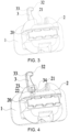
- FIG. 3 is a three-dimensional view of the structure of the buccal tube when the traction hook is in use in the embodiment 1
- FIG. 4 is a view of the internal structure of the buccal tube when the traction hook is in use in the embodiment 1.
- the main body 2 further includes a limiting member 24, and the limiting member 24 is configured to limit a rotation angle of the traction hook 3.
- the limiting member 24 is fixedly connected to the main body 2, and in this embodiment, the limiting member 24 and the main body 2 are integrally formed.
- the limiting member 24 limits a maximum rotation angle of the traction hook 3.
- the main body 2 further includes an elastic limiting member 22 disposed in the accommodation space 21, and the elastic limiting member 22 contacts a side surface of the traction hook 3.
- the elastic limiting member 22 may have arbitrary shapes, and preferably, the surface of the elastic limiting member 22 in contact with the traction hook 3 is a smooth curved surface.
- the elastic limiting member 22 is a cylindrical rod.
- the main body 2 is provided with holes for allowing both ends of the elastic limiting member 22 to be inserted, both ends of the elastic limiting member 22 are respectively inserted into the two holes, and the elastic limiting member 22 may rotate axially.
- the side surface of the traction hook 3 is provided with a third limiting protrusion 34.
- the elastic limiting member 22 abuts against a side wall of the third limiting protrusion 34 to block the traction hook 3 from rotating.
- the elastic limiting member 22 and the third limiting protrusion 34 fix the traction hook 3 to a hidden position, so that the traction hook 3 may not automatically rotate out.
- a force is applied to rotate the traction hook 3 and the third limiting protrusion 34 presses the elastic limiting member 22 to deform the elastic limiting member 22.
- the third limiting protrusion 34 then passes over the elastic limiting member 22, and one end of the traction hook 3 leaves the accommodation space 21.
- the third limiting protrusion 34 presses the elastic limiting member 22 to deform the elastic limiting member 22.
- the third limiting protrusion 34 may then pass over the elastic limiting member 22, and the traction hook 3 returns to the hidden position.
- One end of the traction hook 3 facing the outside of the main body 2 in use is a free end 32.
- a recess 33 is formed on a portion of the traction hook 3 near the free end 32, and the recess 33 makes the free end 32 bulge, which may be configured for hanging a rubber band or a pulling band and the like.
- An outer surface of the free end 32 has a smooth transition and does not contain sharp corners, which may greatly reduce the irritation of the traction hook 3 to the patient's oral mucosa, and food may not be easily hooked.
- the traction hook is configured to allow a rubber band or tension spring to be hooked for intra-maxillary or inter-maxillary traction.
- the traction hook is not applied throughout the entire orthodontic cycle, but only used in the early or middle and late stages of the orthodontic treatment.
- the traction hooks set on the buccal tubes currently available on the market are all fixed traction hooks, and the traction hooks cannot be removed when the traction hooks are not in use.
- the fixed traction hook of the conventional buccal tube is replaced with a movable traction hook.
- the traction hook 3 When the traction hook 3 is not required to be used, the traction hook 3 is hidden in the accommodation space 21 inside the main body 2, and the traction hook 3 is pulled out of the accommodation space 21 when it is required to be used. The patient may not feel uncomfortable when the traction hook 3 is not in use in this way.
- All the traction hooks of the buccal tubes on the market are hooks formed by bending the cylindrical bodies.
- these traction hooks contain a sharp angle structure, which may easily stimulate the oral mucosa of the patient, resulting in a strong foreign body sensation and discomfort.
- these traction hooks easily cause the food to be hooked, resulting in inconvenience for the patient when eating.
- One end of the traction hook 3 facing the outside of the main body 2 in use is the free end 32.
- the fee end 32 bulges, and the outer surface of the free end 32 has a smooth transition and does not contain sharp corners, which may greatly reduce the irritation of the traction hook 3 to the patient's oral mucosa, and food may not be easily hooked.
- FIG. 6 is a three-dimensional view of a structure of a buccal tube with a traction hook in a hidden state in the embodiment 2.
- This embodiment provides a buccal tube including a bottom plate 1 and a main body 2 connected to each other.
- the bottom plate 1 is configured for being directly glued onto an anchoring tooth surface or being glued and fixed onto an anchoring tooth surface through a belt, and the bottom plate 1 and the main body 2 are fixedly connected.
- the main body 2 is provided with a through hole 20 for an arch wire to pass through.
- a shape of the through hole 20 may be a round hole or a square hole known in the market, or may be a hole formed by combining a through slot and a cover plate. In this embodiment, the through hole 20 is a square hole.
- FIG. 1 shows a state of the buccal tube when the traction hook is not in use.
- the main body 2 shown in FIG. 7 is in a perspective state, and the dotted line shows an internal structure of the main body 2.
- the main body 2 is provided with an accommodation space 21, and the traction hook 3 is disposed in the accommodation space 21 when the traction hook 3 is not in use.
- the accommodation space 21 may have arbitrary shapes, and in this embodiment, the accommodation space 21 is an elongated strip space.
- the accommodation space 21 is located above the through hole 20.
- the accommodation space 21 and the through hole 20 may or may not communicate with each other, and in this embodiment, the accommodation space 21 communicates with the through hole 20.
- the main body 2 is provided with an elastic limiting member 22 in the accommodation space 21, the elastic limiting member 22 is configured to limit movement and displacement of the traction hook 3, and the elastic limiting member 22 contacts a side surface of the traction hook 3.
- FIG. 8 is an exploded view of the structure of the buccal tube in the embodiment 2.
- the elastic limiting member 22 may have arbitrary shapes, and preferably, the surface of the elastic limiting member 22 in contact with the traction hook 3 is a smooth curved surface.
- the elastic limiting member 22 is a cylindrical rod.
- the main body 2 is provided with holes for allowing both ends of the elastic limiting member 22 to be inserted, both ends of the elastic limiting member 22 are respectively inserted into the two holes, and the elastic limiting member 22 may rotate axially.
- Two limiting protrusions are formed on the side surface of the traction hook 3, namely, a first limiting protrusion 30 and a second limiting protrusion 31.
- the elastic limiting member 22 abuts against a side wall of the first limiting protrusion 30 to block the traction hook 3 from moving.
- the first limiting protrusion 30 may fix the traction hook 3 to a hidden position, so that the traction hook 3 is prevented from automatically falling out.
- the traction hook 3 When the traction hook 3 is in use, a force is applied to pull one end of the traction hook 3 facing an outer side of the main body 2, and the first limiting protrusion 30 presses the elastic limiting member 22 to deform the elastic limiting member 22. The first limiting protrusion 30 then passes over the elastic limiting member 22, and one end of the traction hook 3 leaves the accommodation space 21.
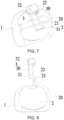
- FIG. 9 is a three-dimensional view of the structure of the buccal tube when the traction hook is in use in the embodiment 2
- FIG. 10 is a view of the internal structure of the buccal tube when the traction hook is in use in the embodiment 2.
- the main body 2 in FIG. 10 is in a perspective state.
- the elastic limiting member 22 abuts against a side wall of the second limiting protrusion 31 to block the traction hook 3 from moving continuously.
- the second limiting protrusion 31 controls maximum displacement of the traction hook 3.
- the two sides of the elastic limiting member 22 respectively abut against the side wall of the first limiting protrusion 30 and the side wall of the second limiting protrusion 31. That is, the first limiting protrusion 30 and the second limiting protrusion 31 clamp the elastic limiting member 22.
- the traction hook is configured to allow a rubber band or tension spring to be hooked for intra-maxillary or inter-maxillary traction.
- the traction hook is not applied throughout the entire orthodontic cycle, but only used in the early or middle and late stages of the orthodontic treatment.
- the traction hooks set on the buccal tubes currently available on the market are all fixed traction hooks, and the traction hooks cannot be removed when the traction hooks are not in use.
- the fixed traction hook of the conventional buccal tube is changed to a movable traction hook.
- the traction hook 3 When the traction hook 3 is not required to be used, the traction hook 3 is hidden in the accommodation space 21 inside the main body 2, and the traction hook 3 is pulled out of the accommodation space 21 when it is required to be used. A patient may not feel uncomfortable when the traction hook 3 is not in use in this way.
- All the traction hooks of the buccal tubes on the market are hooks formed by bending the cylindrical bodies.
- these traction hooks contain a sharp angle structure, which may easily stimulate the oral mucosa of the patient, resulting in a strong feeling of presence of a foreign object and discomfort.
- these traction hooks easily cause the food to be hooked, resulting in inconvenience for the patient when eating.
- One end of the traction hook 3 facing the outside of the main body 2 in use is the free end 32.
- the fee end 32 bulges, and the outer surface of the free end 32 has a smooth transition and does not contain sharp corners, which may greatly reduce the irritation of the traction hook 3 to the patient's oral mucosa, and food may not be easily hooked.
- FIG. 11 is a three-dimensional view of a structure of a buccal tube with a traction hook in a hidden state in the embodiment 3.
- This embodiment provides a buccal tube including a bottom plate 1 and a main body 2 connected to each other.
- the bottom plate 1 is configured for being directly glued or fixed onto an anchoring tooth surface, the bottom plate 1 may also be a common belt, and the bottom plate 1 and the main body 2 are fixedly connected.
- the main body 2 is provided with a through hole 20 for an arch wire to pass through.
- a shape of the through hole 20 may be a round hole or a square hole known in the market, or may be a through hole formed by combining a through slot and a cover plate. In this embodiment, the through hole 20 is a square hole.
- the main body 2 is provided with a traction hook 3 that can rotate relative to it.
- FIG. 11 shows the state of the buccal tube when the traction hook is not in use
- FIG. 12 is a view of an internal structure of the buccal tube when the traction hook is hidden in the embodiment 3.
- the main body 2 shown in FIG. 12 is in a perspective state.
- the dotted line shows an internal structure of the main body 2.
- the main body 2 is provided with an accommodation space 21, and the traction hook 3 is disposed in the accommodation space 21 when the traction hook 3 is not in use.
- the accommodation space 21 may have arbitrary shapes, and in this embodiment, the shape of the accommodation space 21 matches a shape of the traction hook 3 and is shaped as an arc-shaped space.
- an outer surface of the traction hook 3 matches an outer surface of the main body 2 to form a smooth curved surface.
- the smooth curved surface may be any smooth shape, and preferably, the surface may selectively be an ellipsoid-like surface or a spherical-like surface. In this embodiment, the smooth curved surface is shaped as an ellipsoid-like shape.
- the outer surface of the traction hook 3 matches the outer surface of the main body 2 to form a smooth curved surface, so that irritation generated by the buccal tube to the oral mucosa of a patient is greatly reduced, and the patient may thus feel less discomfort.
- the main body 2 is provided with a rotating shaft 23, and the traction hook 3 is rotatably connected to the main body 2 through the rotating shaft 23.
- a direction of the rotating shaft 23 may be set arbitrarily, and in this embodiment, the rotating shaft 23 is perpendicular to the bottom plate 1.
- the main body 2 is provided with an elastic limiting member 22 in the accommodation space 21, the elastic limiting member 22 is configured to limit a rotation angle of the traction hook 3, and the elastic limiting member 22 contacts a side surface of the traction hook 3.
- FIG. 13 is an exploded view of the structure of the buccal tube in the embodiment 3.
- the end of the traction hook 3 facing the outside of the main body 2 in use is a free end 32.
- the free end 32 is in the shape of a hook
- the outer surface of the end of the traction hook 3 facing the outside of the main body 2 is in the shape of a smooth curved surface.
- the outer surface of the traction hook 3 has a smooth transition and does not contain sharp corners, which may greatly reduce the irritation of the traction hook 3 to the patient's oral mucosa, and food may not be easily hooked.
- a shape of the elastic limiting member 22 may be arbitrary, and preferably, the surface of the elastic limiting member 22 in contact with the traction hook 3 is a smooth curved surface.
- the elastic limiting member 22 is a cylindrical rod, and the main body 2 is fixedly connected to the elastic limiting member 22.
- Two limiting protrusions are formed on the side surface of the traction hook 3, namely, a first limiting protrusion 30 and a second limiting protrusion 31.
- the elastic limiting member 22 abuts against a side wall of the first limiting protrusion 30 to block the traction hook 3 from rotating.
- the first limiting protrusion 30 and the elastic limiting member 22 may fix the traction hook 3 to a hidden position, so that the traction hook 3 is prevented from automatically rotating out.
- a force is applied to rotate one end of the traction hook 3 facing an outer side of the main body 2, and the first limiting protrusion 30 presses the elastic limiting member 22 to deform the elastic limiting member 22.
- the first limiting protrusion 30 then passes over the elastic limiting member 22, and one end of the traction hook 3 leaves the accommodation space 21.
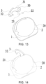
- FIG. 14 is a three-dimensional view of the structure of the buccal tube when the traction hook is in use in the embodiment 3
- FIG. 15 is a view of the internal structure of the buccal tube when the traction hook is in use in the embodiment 3.
- the main body 2 in FIG. 15 is in a perspective state.
- the elastic limiting member 22 abuts against a side wall of the second limiting protrusion 31 to block the traction hook 3 from rotating continuously.
- the second limiting protrusion 31 limits a maximum rotation angle of the traction hook 3.
- the two sides of the elastic limiting member 22 respectively abut against the side wall of the first limiting protrusion 30 and the side wall of the second limiting protrusion 31. That is, the first limiting protrusion 30 and the second limiting protrusion 31 clamp the elastic limiting member 22.
- FIG. 16 is a three-dimensional view of a structure of a buccal tube with a traction hook in a hidden state in the embodiment 4.
- This embodiment provides a buccal tube including a bottom plate 1 and a main body 2 connected to each other.
- the bottom plate 1 is configured for being directly glued onto an anchoring tooth surface or being glued and fixed on to an anchoring tooth surface through a belt, and the bottom plate 1 and the main body 2 are fixedly connected.
- the main body 2 is provided with a through hole 20 for an arch wire to pass through.
- a shape of the through hole 20 may be a round hole or a square hole known in the market, or may be a through hole formed by combining a through slot and a cover plate. In this embodiment, the through hole 20 is a square hole.
- the main body 2 is provided with a traction hook 3 that can rotate relative to it.
- an outer surface of the traction hook 3 matches an outer surface of the main body 2 to form a smooth curved surface.
- the smooth curved surface may be any smooth shape, and preferably, the surface may selectively be an ellipsoid-shaped surface or a spherical-shaped surface. In this embodiment, the smooth curved surface is shaped as an ellipsoid-shaped shape.
- the outer surface of the traction hook 3 matches the outer surface of the main body 2 to form a smooth curved surface, so that irritation generated by the buccal tube to the oral mucosa of a patient is greatly reduced, and the patient may thus feel less discomfort.
- FIG. 17 is a three-dimensional view of the structure of the buccal tube when the traction hook is in use in the embodiment 4.
- the main body 2 is provided with an accommodation space 21, and the traction hook 3 is disposed in the accommodation space 21 when the traction hook 3 is not in use.
- the accommodation space 21 may have arbitrary shapes, and in this embodiment, the shape of the accommodation space 21 matches a shape of the traction hook 3.
- the traction hook 3 may be used by rotating the traction hook 3 with a tool such as a hook.
- FIG. 18 is an exploded view of the structure of the buccal tube in the embodiment 4.
- the main body is provided with a rotating shaft 23, and the traction hook 3 is rotatably connected to the main body 2 through the rotating shaft 23.
- a direction of the rotating shaft 23 may be set arbitrarily, and in this embodiment, the rotating shaft 23 is parallel to the bottom plate 1.
- the main body 2 is provided with holes 25 into which both ends of the rotating shaft 23 are inserted. Both ends of the rotating shaft 23 are inserted into the hole 25, and the rotating shaft 23 may rotate around an axis in the hole 25.
- the main body 2 further includes a limiting member 24 disposed in the accommodation space 21, and the limiting member 24 is configured to limit a rotation angle of the traction hook 3.
- the limiting member 24 is fixedly connected to the main body 2, and in this embodiment, the limiting member 24 and the main body 2 are integrally formed. When the traction hook 3 rotates to a use position, the limiting member 24 abuts against the traction hook 3 to block the traction hook 3 from rotating further.
- the limiting member 24 limits a maximum rotation angle of the traction hook 3.
- One end of the traction hook 3 facing the outside of the main body 2 in use is a free end 32.
- a recess 33 is formed on a portion of the traction hook 3 near the free end 32, and the recess 33 makes the free end 32 bulge, which may be configured for hanging a rubber band or a pulling band and the like.
- An outer surface of the free end 32 has a smooth transition and does not contain sharp corners, which may greatly reduce the irritation of the traction hook 3 to the patient's oral mucosa, and food may not be easily hooked.
- the traction hook 3 is disposed on an upper side of the main body 2, and the traction hook 3 may be kept hidden under the action of gravity.
- the traction hook 3 is hooked out by a hook, and the traction hook 3 may be kept in the use position by traction members such as a rubber band and a tension spring.
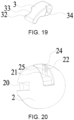
- FIG. 19 is a three-dimensional view of the structure of the buccal tube in the embodiment 4, and FIG. 20 is a three-dimensional view of a structure of a main body in the embodiment 4.
- the main body 2 is provided with an elastic limiting member 22 in the accommodation space 21.
- the side surface of the traction hook 3 is provided with a third limiting protrusion 34.
- the elastic limiting member 22 abuts against a side wall of the third limiting protrusion 34 to block the traction hook 3 from rotating.
- the elastic limiting member 22 and the third limiting protrusion 34 fix the traction hook 3 to the hidden position, so that the traction hook 3 may not automatically rotate out.
- the third limiting protrusion 34 presses the elastic limiting member 22 to deform the elastic limiting member 22.
- the third limiting protrusion 34 then passes over the elastic limiting member 22, and one end of the traction hook 3 leaves the accommodation space 21.
- the third limiting protrusion 34 abuts against the limiting member 24 to block the traction hook 3 from rotating further.
- the limiting member 24 limits a maximum rotation angle of the traction hook 3.
- both sides of the third limiting protrusion 34 respectively abut against the elastic limiting member 22 and the limiting member 24. That is, the elastic limiting member 22 and the limiting member 24 clamp the third limiting protrusion 34 to fix the traction hook 3 to the use position and cannot rotate.
- a force is only required to be inwardly applied to rotate the traction hook 3, and the third limiting protrusion 34 presses the elastic limiting member 22 to deform the elastic limiting member 22.
- the third limiting protrusion 34 may then pass over the elastic limiting member 22, and the traction hook 3 returns to the hidden position.
Landscapes
- Health & Medical Sciences (AREA)
- Oral & Maxillofacial Surgery (AREA)
- Dentistry (AREA)
- Epidemiology (AREA)
- Life Sciences & Earth Sciences (AREA)
- Animal Behavior & Ethology (AREA)
- General Health & Medical Sciences (AREA)
- Public Health (AREA)
- Veterinary Medicine (AREA)
- Dental Tools And Instruments Or Auxiliary Dental Instruments (AREA)
Description
- The disclosure relates to an orthodontic buccal tube.
- The buccal tube is an important part of the orthodontic fixed appliance and consists of a hollow tube, a traction hook, and a base plate. Generally, the buccal tube is glued directly onto the anchoring tooth surface or is glued and fixed onto the anchoring tooth surface through a belt ring. The orthodontics arch wire passes through the hollow tube of the buccal tube, and the buccal tube may fix the arch wire. A traction hook is provided on the buccal tube and is configured to allow a rubber band or tension spring to be hooked for intra-maxillary or inter-maxillary traction. Usually, the traction hook is not applied throughout the entire orthodontic cycle, but only used in the early or middle and late stages of the orthodontic treatment. However, the traction hooks set on the buccal tubes currently available on the market are all fixed traction hooks, and at present, the traction hooks cannot be removed when the traction hooks of the buccal tubes are not in use. Due to its functional requirements, the structure of the traction hook may generate irritation to the oral mucosa, and a patient may easily feel foreign body sensation. In addition, the traction hooks currently available on the market all contain a sharp angle structure, which brings discomfort to the patient. In order to reduce patient's foreign body sensation, a buccal tube in which the traction hook may be hidden when not in use is provided, and the discomfort brought to the patient during the use of the buccal tube may be greatly reduced.
-
CN 200 987 705 Y discloses a buccal tube comprising a traction hook that can be set to active or inactive positions through rotation. - In view of the above technical problems, the disclosure provides a buccal tube with a hidden hook according to the appended claims.
- The technical solutions adopted by the disclosure to solve the technical problem include the following.
- A buccal tube includes a bottom plate and a main body connected to each other. The main body is provided with a traction hook which is movable or rotatable relative to the main body. When the traction hook is not in use, the main body is internally provided with an accommodation space, and the traction hook is disposed in the accommodation space. When the traction hook is in use, one end of the traction hook outwardly rotates or moves away from the accommodation space.
- Compared to the related art, the effects of the disclosure include the following. The disclosure provides a buccal tube with a hidden traction hook. The buccal tube includes a bottom plate and a main body that are connected to each other. The main body is provided with the traction hook which can move or rotate relative to the main body, and the main body is internally provided with an accommodation space. When the traction hook is not in use, the traction hook is disposed in the accommodation space. When the traction hook is in use, the traction hook outwardly rotates or moves away from the accommodation space. A fixed traction hook, which is provided on a conventional buccal tube, is modified into the rotatable or movable traction hook, such that when the traction hook does not need to be used, same is hidden in the accommodation space so as to greatly reduce the irritation of the traction hook to the oral mucosa of a patient to relieve the patient's discomfort. When the traction hook needs to be used, same is rotated or moved and is taken out from the accommodation space, which does not affect the use of the traction hook.
- The disclosure is further described in detail in combination with accompanying figures and embodiments.
-
-
FIG. 1 is a three-dimensional view of a structure of a buccal tube with a traction hook in a hidden state in anembodiment 1. -
FIG. 2 is a view of an internal structure of the buccal tube with the traction hook in the hidden state in theembodiment 1. -
FIG. 3 is a three-dimensional view of the structure of the buccal tube when the traction hook is in use in theembodiment 1. -
FIG. 4 is a view of the internal structure of the buccal tube when the traction hook is in use in theembodiment 1. -
FIG. 5 is a three-dimensional view of the structure of the buccal tube when the traction hook is in use from another viewing angle in theembodiment 1. -
FIG. 6 is a three-dimensional view of a structure of a buccal tube with a traction hook in a hidden state in anembodiment 2. -
FIG. 7 is a view of an internal structure of the buccal tube with the traction hook in the hidden state in theembodiment 2. -
FIG. 8 is an exploded view of the structure of the buccal tube in theembodiment 2. -
FIG. 9 is a three-dimensional view of the structure of the buccal tube when the traction hook is in use in theembodiment 2. -
FIG. 10 is a view of the internal structure of the buccal tube when the traction hook is in use in theembodiment 2. -
FIG. 11 is a three-dimensional view of a structure of a buccal tube with a traction hook in a hidden state in anembodiment 3. -
FIG. 12 is a view of an internal structure of the buccal tube with the traction hook in the hidden state in theembodiment 3. -
FIG. 13 is an exploded view of the structure of the buccal tube in theembodiment 3. -
FIG. 14 is a three-dimensional view of the structure of the buccal tube when the traction hook is in use in theembodiment 3. -
FIG. 15 is a view of the internal structure of the buccal tube when the traction hook is in use in theembodiment 3. -
FIG. 16 is a three-dimensional view of a structure of a buccal tube with a traction hook in a hidden state in an embodiment 4. -
FIG. 17 is a three-dimensional view of the structure of the buccal tube when the traction hook is in use in the embodiment 4. -
FIG. 18 is an exploded view of the structure of the buccal tube in the embodiment 4. -
FIG. 19 is a three-dimensional view of the structure of the buccal tube in the embodiment 4. -
FIG. 20 is a three-dimensional view of a structure of a main body in the embodiment 4. - With reference to
FIG. 1, FIG. 1 is a three-dimensional view of a structure of a buccal tube with a traction hook in a hidden state in theembodiment 1. This embodiment provides a buccal tube including abottom plate 1 and amain body 2 connected to each other. Thebottom plate 1 is configured for being directly glued onto an anchoring tooth surface or being glued and fixed onto an anchoring tooth surface through a belt, and thebottom plate 1 and themain body 2 are fixedly connected. - The
main body 2 is provided with athrough hole 20 for an arch wire to pass therethrough. A shape of the throughhole 20 may be a round hole or a square hole known in the market, or may be a hole formed by combining a through slot and a cover plate. In this embodiment, thethrough hole 20 is a hole formed by the combination of the through slot and the cover plate. Themain body 2 is provided with atraction hook 3 that can rotate relative thereto. In order to show the structure of the buccal tube conveniently,FIG. 2 shows an internal state of the buccal tube when the traction hook is not in use and themain body 2 inFIG. 2 is in a perspective state. As can be seen fromFIG. 2 , themain body 2 is provided with anaccommodation space 21, and when thetraction hook 3 is not in use, thetraction hook 3 is disposed in theaccommodation space 21. Theaccommodation space 21 may have arbitrary shapes, and in this embodiment, the shape of theaccommodation space 21 matches a shape of thetraction hook 3. Theaccommodation space 21 and the throughhole 20 may or may not communicate with each other, and in this embodiment, theaccommodation space 21 does not communicate with the throughhole 20. When thetraction hook 3 is disposed in theaccommodation space 21, an outer surface of thetraction hook 3 matches an outer surface of themain body 2 to form a smooth curved surface. In this embodiment, the outer surface of thetraction hook 3 matches the outer surface of themain body 2 to form a smooth curved surface similar to a semi-cylindrical surface. The buccal tubes currently available on the market are all semi-cylindrical, two ends which the through hole penetrates therethrough have sharp structures, and the traction hook also has a sharp structure, which may cause a patient to have a strong foreign body sensation, and the patient may thereby experience a poor using experience. The traction hook provided by this embodiment may be hidden, and the outer surface of the buccal tube forms a smooth curved surface, so that the patient may enjoy an improved using experience. - With reference to
FIG. 3 to FIG. 4, FIG. 3 is a three-dimensional view of the structure of the buccal tube when the traction hook is in use in theembodiment 1, andFIG. 4 is a view of the internal structure of the buccal tube when the traction hook is in use in theembodiment 1. Themain body 2 further includes a limitingmember 24, and the limitingmember 24 is configured to limit a rotation angle of thetraction hook 3. The limitingmember 24 is fixedly connected to themain body 2, and in this embodiment, the limitingmember 24 and themain body 2 are integrally formed. When thetraction hook 3 rotates to a use position, the limitingmember 24 abuts against thetraction hook 3 to block thetraction hook 3 from rotating further. The limitingmember 24 limits a maximum rotation angle of thetraction hook 3. - The
main body 2 further includes an elastic limitingmember 22 disposed in theaccommodation space 21, and the elastic limitingmember 22 contacts a side surface of thetraction hook 3. The elastic limitingmember 22 may have arbitrary shapes, and preferably, the surface of the elastic limitingmember 22 in contact with thetraction hook 3 is a smooth curved surface. In this embodiment, the elastic limitingmember 22 is a cylindrical rod. Themain body 2 is provided with holes for allowing both ends of the elastic limitingmember 22 to be inserted, both ends of the elastic limitingmember 22 are respectively inserted into the two holes, and the elastic limitingmember 22 may rotate axially. - The side surface of the
traction hook 3 is provided with a third limitingprotrusion 34. When the traction hook is not in use, the elastic limitingmember 22 abuts against a side wall of the third limitingprotrusion 34 to block thetraction hook 3 from rotating. The elastic limitingmember 22 and the third limitingprotrusion 34 fix thetraction hook 3 to a hidden position, so that thetraction hook 3 may not automatically rotate out. When thetraction hook 3 is in use, a force is applied to rotate thetraction hook 3, and the third limitingprotrusion 34 presses the elastic limitingmember 22 to deform the elastic limitingmember 22. The third limitingprotrusion 34 then passes over the elastic limitingmember 22, and one end of thetraction hook 3 leaves theaccommodation space 21. - When the
traction hook 3 is required to rotate back to the hidden position, a force is only required to be inwardly applied to rotate thetraction hook 3, and the third limitingprotrusion 34 presses the elastic limitingmember 22 to deform the elastic limitingmember 22. The third limitingprotrusion 34 may then pass over the elastic limitingmember 22, and thetraction hook 3 returns to the hidden position. - One end of the
traction hook 3 facing the outside of themain body 2 in use is afree end 32. Arecess 33 is formed on a portion of thetraction hook 3 near thefree end 32, and therecess 33 makes thefree end 32 bulge, which may be configured for hanging a rubber band or a pulling band and the like. An outer surface of thefree end 32 has a smooth transition and does not contain sharp corners, which may greatly reduce the irritation of thetraction hook 3 to the patient's oral mucosa, and food may not be easily hooked. - The traction hook is configured to allow a rubber band or tension spring to be hooked for intra-maxillary or inter-maxillary traction. Usually, the traction hook is not applied throughout the entire orthodontic cycle, but only used in the early or middle and late stages of the orthodontic treatment. However, the traction hooks set on the buccal tubes currently available on the market are all fixed traction hooks, and the traction hooks cannot be removed when the traction hooks are not in use. In the buccal tube provided in this embodiment, the fixed traction hook of the conventional buccal tube is replaced with a movable traction hook. When the
traction hook 3 is not required to be used, thetraction hook 3 is hidden in theaccommodation space 21 inside themain body 2, and thetraction hook 3 is pulled out of theaccommodation space 21 when it is required to be used. The patient may not feel uncomfortable when thetraction hook 3 is not in use in this way. - All the traction hooks of the buccal tubes on the market are hooks formed by bending the cylindrical bodies. On the one hand, these traction hooks contain a sharp angle structure, which may easily stimulate the oral mucosa of the patient, resulting in a strong foreign body sensation and discomfort. On the other hand, during the patient's eating process, these traction hooks easily cause the food to be hooked, resulting in inconvenience for the patient when eating. One end of the
traction hook 3 facing the outside of themain body 2 in use is thefree end 32. Thefee end 32 bulges, and the outer surface of thefree end 32 has a smooth transition and does not contain sharp corners, which may greatly reduce the irritation of thetraction hook 3 to the patient's oral mucosa, and food may not be easily hooked. - With reference to
FIG. 6, FIG. 6 is a three-dimensional view of a structure of a buccal tube with a traction hook in a hidden state in theembodiment 2. This embodiment provides a buccal tube including abottom plate 1 and amain body 2 connected to each other. Thebottom plate 1 is configured for being directly glued onto an anchoring tooth surface or being glued and fixed onto an anchoring tooth surface through a belt, and thebottom plate 1 and themain body 2 are fixedly connected. Themain body 2 is provided with a throughhole 20 for an arch wire to pass through. A shape of the throughhole 20 may be a round hole or a square hole known in the market, or may be a hole formed by combining a through slot and a cover plate. In this embodiment, the throughhole 20 is a square hole. Themain body 2 is provided with atraction hook 3 that can move relative thereto.FIG. 1 shows a state of the buccal tube when the traction hook is not in use. In order to conveniently show the structure of the buccal tube, themain body 2 shown inFIG. 7 is in a perspective state, and the dotted line shows an internal structure of themain body 2. As can be seen fromFIG. 7 , themain body 2 is provided with anaccommodation space 21, and thetraction hook 3 is disposed in theaccommodation space 21 when thetraction hook 3 is not in use. Theaccommodation space 21 may have arbitrary shapes, and in this embodiment, theaccommodation space 21 is an elongated strip space. Theaccommodation space 21 is located above the throughhole 20. Theaccommodation space 21 and the throughhole 20 may or may not communicate with each other, and in this embodiment, theaccommodation space 21 communicates with the throughhole 20. - The
main body 2 is provided with an elastic limitingmember 22 in theaccommodation space 21, the elastic limitingmember 22 is configured to limit movement and displacement of thetraction hook 3, and the elastic limitingmember 22 contacts a side surface of thetraction hook 3. - With reference to
FIG. 8, FIG. 8 is an exploded view of the structure of the buccal tube in theembodiment 2. The elastic limitingmember 22 may have arbitrary shapes, and preferably, the surface of the elastic limitingmember 22 in contact with thetraction hook 3 is a smooth curved surface. In this embodiment, the elastic limitingmember 22 is a cylindrical rod. Themain body 2 is provided with holes for allowing both ends of the elastic limitingmember 22 to be inserted, both ends of the elastic limitingmember 22 are respectively inserted into the two holes, and the elastic limitingmember 22 may rotate axially. - Two limiting protrusions are formed on the side surface of the
traction hook 3, namely, a first limitingprotrusion 30 and a second limitingprotrusion 31. When the traction hook is not in use, the elastic limitingmember 22 abuts against a side wall of the first limitingprotrusion 30 to block thetraction hook 3 from moving. The first limitingprotrusion 30 may fix thetraction hook 3 to a hidden position, so that thetraction hook 3 is prevented from automatically falling out. - When the
traction hook 3 is in use, a force is applied to pull one end of thetraction hook 3 facing an outer side of themain body 2, and the first limitingprotrusion 30 presses the elastic limitingmember 22 to deform the elastic limitingmember 22. The first limitingprotrusion 30 then passes over the elastic limitingmember 22, and one end of thetraction hook 3 leaves theaccommodation space 21. - With reference to
FIG. 9 to FIG. 10, FIG. 9 is a three-dimensional view of the structure of the buccal tube when the traction hook is in use in theembodiment 2, andFIG. 10 is a view of the internal structure of the buccal tube when the traction hook is in use in theembodiment 2. In order to conveniently show the internal structure, themain body 2 inFIG. 10 is in a perspective state. When thetraction hook 3 moves to a use position, the elastic limitingmember 22 abuts against a side wall of the second limitingprotrusion 31 to block thetraction hook 3 from moving continuously. The second limitingprotrusion 31 controls maximum displacement of thetraction hook 3. In order to better fix thetraction hook 3 to the use position, when thetraction hook 3 moves to the use position, the two sides of the elastic limitingmember 22 respectively abut against the side wall of the first limitingprotrusion 30 and the side wall of the second limitingprotrusion 31. That is, the first limitingprotrusion 30 and the second limitingprotrusion 31 clamp the elastic limitingmember 22. - The traction hook is configured to allow a rubber band or tension spring to be hooked for intra-maxillary or inter-maxillary traction. Usually, the traction hook is not applied throughout the entire orthodontic cycle, but only used in the early or middle and late stages of the orthodontic treatment. However, the traction hooks set on the buccal tubes currently available on the market are all fixed traction hooks, and the traction hooks cannot be removed when the traction hooks are not in use. In the buccal tube provided in this embodiment, the fixed traction hook of the conventional buccal tube is changed to a movable traction hook. When the
traction hook 3 is not required to be used, thetraction hook 3 is hidden in theaccommodation space 21 inside themain body 2, and thetraction hook 3 is pulled out of theaccommodation space 21 when it is required to be used. A patient may not feel uncomfortable when thetraction hook 3 is not in use in this way. - All the traction hooks of the buccal tubes on the market are hooks formed by bending the cylindrical bodies. On the one hand, these traction hooks contain a sharp angle structure, which may easily stimulate the oral mucosa of the patient, resulting in a strong feeling of presence of a foreign object and discomfort. On the other hand, during the patient's eating process, these traction hooks easily cause the food to be hooked, resulting in inconvenience for the patient when eating. One end of the
traction hook 3 facing the outside of themain body 2 in use is thefree end 32. Thefee end 32 bulges, and the outer surface of thefree end 32 has a smooth transition and does not contain sharp corners, which may greatly reduce the irritation of thetraction hook 3 to the patient's oral mucosa, and food may not be easily hooked. - With reference to
FIG. 11, FIG. 11 is a three-dimensional view of a structure of a buccal tube with a traction hook in a hidden state in theembodiment 3. This embodiment provides a buccal tube including abottom plate 1 and amain body 2 connected to each other. Thebottom plate 1 is configured for being directly glued or fixed onto an anchoring tooth surface, thebottom plate 1 may also be a common belt, and thebottom plate 1 and themain body 2 are fixedly connected. Themain body 2 is provided with a throughhole 20 for an arch wire to pass through. A shape of the throughhole 20 may be a round hole or a square hole known in the market, or may be a through hole formed by combining a through slot and a cover plate. In this embodiment, the throughhole 20 is a square hole. Themain body 2 is provided with atraction hook 3 that can rotate relative to it.FIG. 11 shows the state of the buccal tube when the traction hook is not in use, andFIG. 12 is a view of an internal structure of the buccal tube when the traction hook is hidden in theembodiment 3. In order to conveniently show the structure of the buccal tube, themain body 2 shown inFIG. 12 is in a perspective state. The dotted line shows an internal structure of themain body 2. As can be seen fromFIG. 12 , themain body 2 is provided with anaccommodation space 21, and thetraction hook 3 is disposed in theaccommodation space 21 when thetraction hook 3 is not in use. Theaccommodation space 21 may have arbitrary shapes, and in this embodiment, the shape of theaccommodation space 21 matches a shape of thetraction hook 3 and is shaped as an arc-shaped space. - When the
traction hook 3 is disposed in theaccommodation space 21, an outer surface of thetraction hook 3 matches an outer surface of themain body 2 to form a smooth curved surface. The smooth curved surface may be any smooth shape, and preferably, the surface may selectively be an ellipsoid-like surface or a spherical-like surface. In this embodiment, the smooth curved surface is shaped as an ellipsoid-like shape. The outer surface of thetraction hook 3 matches the outer surface of themain body 2 to form a smooth curved surface, so that irritation generated by the buccal tube to the oral mucosa of a patient is greatly reduced, and the patient may thus feel less discomfort. - The
main body 2 is provided with arotating shaft 23, and thetraction hook 3 is rotatably connected to themain body 2 through the rotatingshaft 23. A direction of therotating shaft 23 may be set arbitrarily, and in this embodiment, the rotatingshaft 23 is perpendicular to thebottom plate 1. - The
main body 2 is provided with an elastic limitingmember 22 in theaccommodation space 21, the elastic limitingmember 22 is configured to limit a rotation angle of thetraction hook 3, and the elastic limitingmember 22 contacts a side surface of thetraction hook 3. - With reference to
FIG. 13, FIG. 13 is an exploded view of the structure of the buccal tube in theembodiment 3. The end of thetraction hook 3 facing the outside of themain body 2 in use is afree end 32. Thefree end 32 is in the shape of a hook, and the outer surface of the end of thetraction hook 3 facing the outside of themain body 2 is in the shape of a smooth curved surface. The outer surface of thetraction hook 3 has a smooth transition and does not contain sharp corners, which may greatly reduce the irritation of thetraction hook 3 to the patient's oral mucosa, and food may not be easily hooked. A shape of the elastic limitingmember 22 may be arbitrary, and preferably, the surface of the elastic limitingmember 22 in contact with thetraction hook 3 is a smooth curved surface. In this embodiment, the elastic limitingmember 22 is a cylindrical rod, and themain body 2 is fixedly connected to the elastic limitingmember 22. - Two limiting protrusions are formed on the side surface of the
traction hook 3, namely, a first limitingprotrusion 30 and a second limitingprotrusion 31. When the traction hook is not in use, the elastic limitingmember 22 abuts against a side wall of the first limitingprotrusion 30 to block thetraction hook 3 from rotating. The first limitingprotrusion 30 and the elastic limitingmember 22 may fix thetraction hook 3 to a hidden position, so that thetraction hook 3 is prevented from automatically rotating out. When thetraction hook 3 is in use, a force is applied to rotate one end of thetraction hook 3 facing an outer side of themain body 2, and the first limitingprotrusion 30 presses the elastic limitingmember 22 to deform the elastic limitingmember 22. The first limitingprotrusion 30 then passes over the elastic limitingmember 22, and one end of thetraction hook 3 leaves theaccommodation space 21. - With reference to
FIG. 14 to FIG. 15 ,FIG. 14 is a three-dimensional view of the structure of the buccal tube when the traction hook is in use in theembodiment 3, andFIG. 15 is a view of the internal structure of the buccal tube when the traction hook is in use in theembodiment 3. In order to conveniently show the internal structure, themain body 2 inFIG. 15 is in a perspective state. When thetraction hook 3 rotates to a use position, the elastic limitingmember 22 abuts against a side wall of the second limitingprotrusion 31 to block thetraction hook 3 from rotating continuously. The second limitingprotrusion 31 limits a maximum rotation angle of thetraction hook 3. In order to better fix thetraction hook 3 to the use position, when thetraction hook 3 rotates to the use position, the two sides of the elastic limitingmember 22 respectively abut against the side wall of the first limitingprotrusion 30 and the side wall of the second limitingprotrusion 31. That is, the first limitingprotrusion 30 and the second limitingprotrusion 31 clamp the elastic limitingmember 22. - With reference to
FIG. 16, FIG. 16 is a three-dimensional view of a structure of a buccal tube with a traction hook in a hidden state in the embodiment 4. This embodiment provides a buccal tube including abottom plate 1 and amain body 2 connected to each other. Thebottom plate 1 is configured for being directly glued onto an anchoring tooth surface or being glued and fixed on to an anchoring tooth surface through a belt, and thebottom plate 1 and themain body 2 are fixedly connected. Themain body 2 is provided with a throughhole 20 for an arch wire to pass through. A shape of the throughhole 20 may be a round hole or a square hole known in the market, or may be a through hole formed by combining a through slot and a cover plate. In this embodiment, the throughhole 20 is a square hole. Themain body 2 is provided with atraction hook 3 that can rotate relative to it. - When the
traction hook 3 is disposed in theaccommodation space 21, an outer surface of thetraction hook 3 matches an outer surface of themain body 2 to form a smooth curved surface. The smooth curved surface may be any smooth shape, and preferably, the surface may selectively be an ellipsoid-shaped surface or a spherical-shaped surface. In this embodiment, the smooth curved surface is shaped as an ellipsoid-shaped shape. The outer surface of thetraction hook 3 matches the outer surface of themain body 2 to form a smooth curved surface, so that irritation generated by the buccal tube to the oral mucosa of a patient is greatly reduced, and the patient may thus feel less discomfort. - With reference to
FIG. 17, FIG. 17 is a three-dimensional view of the structure of the buccal tube when the traction hook is in use in the embodiment 4. As can be seen fromFIG. 17 , themain body 2 is provided with anaccommodation space 21, and thetraction hook 3 is disposed in theaccommodation space 21 when thetraction hook 3 is not in use. Theaccommodation space 21 may have arbitrary shapes, and in this embodiment, the shape of theaccommodation space 21 matches a shape of thetraction hook 3. When thetraction hook 3 is in use, thetraction hook 3 may be used by rotating thetraction hook 3 with a tool such as a hook. - With reference to
FIG. 18, FIG. 18 is an exploded view of the structure of the buccal tube in the embodiment 4. The main body is provided with arotating shaft 23, and thetraction hook 3 is rotatably connected to themain body 2 through the rotatingshaft 23. A direction of therotating shaft 23 may be set arbitrarily, and in this embodiment, the rotatingshaft 23 is parallel to thebottom plate 1. Themain body 2 is provided withholes 25 into which both ends of therotating shaft 23 are inserted. Both ends of therotating shaft 23 are inserted into thehole 25, and therotating shaft 23 may rotate around an axis in thehole 25. - The
main body 2 further includes a limitingmember 24 disposed in theaccommodation space 21, and the limitingmember 24 is configured to limit a rotation angle of thetraction hook 3. The limitingmember 24 is fixedly connected to themain body 2, and in this embodiment, the limitingmember 24 and themain body 2 are integrally formed. When thetraction hook 3 rotates to a use position, the limitingmember 24 abuts against thetraction hook 3 to block thetraction hook 3 from rotating further. The limitingmember 24 limits a maximum rotation angle of thetraction hook 3. - One end of the
traction hook 3 facing the outside of themain body 2 in use is afree end 32. Arecess 33 is formed on a portion of thetraction hook 3 near thefree end 32, and therecess 33 makes thefree end 32 bulge, which may be configured for hanging a rubber band or a pulling band and the like. An outer surface of thefree end 32 has a smooth transition and does not contain sharp corners, which may greatly reduce the irritation of thetraction hook 3 to the patient's oral mucosa, and food may not be easily hooked. - The
traction hook 3 is disposed on an upper side of themain body 2, and thetraction hook 3 may be kept hidden under the action of gravity. Thetraction hook 3 is hooked out by a hook, and thetraction hook 3 may be kept in the use position by traction members such as a rubber band and a tension spring. - In order to further improve the solution, regarding fixing of the
traction hook 3 to a hidden position and the use position, an optimized implementation is introduced below. - With reference to
FIG. 19 to FIG. 20, FIG. 19 is a three-dimensional view of the structure of the buccal tube in the embodiment 4, andFIG. 20 is a three-dimensional view of a structure of a main body in the embodiment 4. Themain body 2 is provided with an elastic limitingmember 22 in theaccommodation space 21. The side surface of thetraction hook 3 is provided with a third limitingprotrusion 34. When the traction hook is not in use, the elastic limitingmember 22 abuts against a side wall of the third limitingprotrusion 34 to block thetraction hook 3 from rotating. The elastic limitingmember 22 and the third limitingprotrusion 34 fix thetraction hook 3 to the hidden position, so that thetraction hook 3 may not automatically rotate out. When thetraction hook 3 is in use, a force is applied to rotate one end of thetraction hook 3 facing an outer side of themain body 2, and the third limitingprotrusion 34 presses the elastic limitingmember 22 to deform the elastic limitingmember 22. The third limitingprotrusion 34 then passes over the elastic limitingmember 22, and one end of thetraction hook 3 leaves theaccommodation space 21. When thetraction hook 3 rotates to the use position, the third limitingprotrusion 34 abuts against the limitingmember 24 to block thetraction hook 3 from rotating further. The limitingmember 24 limits a maximum rotation angle of thetraction hook 3. - In a further optimized embodiment, when the
traction hook 3 rotates to the use position, both sides of the third limitingprotrusion 34 respectively abut against the elastic limitingmember 22 and the limitingmember 24. That is, the elastic limitingmember 22 and the limitingmember 24 clamp the third limitingprotrusion 34 to fix thetraction hook 3 to the use position and cannot rotate. When thetraction hook 3 is required to rotate back to the hidden position, a force is only required to be inwardly applied to rotate thetraction hook 3, and the third limitingprotrusion 34 presses the elastic limitingmember 22 to deform the elastic limitingmember 22. The third limitingprotrusion 34 may then pass over the elastic limitingmember 22, and thetraction hook 3 returns to the hidden position.
Claims (13)
- A buccal tube, comprising a bottom plate (1) and a main body (2) connected to each other, wherein the main body (2) is provided with a traction hook (3) which is movable relative to the main body (2), the main body (2) is internally provided with an accommodation space (21), when the traction hook (3) is not in use, the traction hook (3) is disposed in the accommodation space (21), when the traction hook (3) is in use, one end of the traction hook (3) outwardly moves away from the accommodation space (21), and the main body (2) comprises a limiting member (24) configured to limit a movement displacement of the traction hook (3), characterized in thatthe limiting member (24) comprises an elastic limiting member (22) disposed in the accommodation space (21), andtwo limiting protrusions (30, 31) are formed on a side surface of the traction hook (3), when the traction hook (3) is not in use, the elastic limiting member (22) abuts against a side wall of a first limiting protrusion (30) to block the traction hook (3) from moving, when the traction hook (3) is in use, a force is applied to move the traction hook (3), the first limiting protrusion (30) presses the elastic limiting member (22) to deform the elastic limiting member (22), and the first limiting protrusion (30) then passes over the elastic limiting member, and when the traction hook (3) moves to a use position, the elastic limiting member (22) abuts against a side wall of a second limiting protrusion (31) and blocks the traction hook (3) from moving continuously.
- The buccal tube according to claim 1, characterized in that the accommodation space (21) is an elongated space, one end of the traction hook (3) is inserted into the accommodation space (21), and the traction hook (3) moves in an extending direction of the accommodation space (21).
- The buccal tube according to claim 1, characterized in that when the traction hook (3) moves to the use position, two sides of the elastic limiting member (22) respectively abut against the side wall of the first limiting protrusion (30) and the side wall of the second limiting protrusion (31).
- A buccal tube, comprising a bottom plate (1) and a main body (2) connected to each other, wherein the main body (2) is provided with a traction hook (3) which is rotatable relative to the main body (2), the main body (2) is internally provided with an accommodation space (21), when the traction hook (3) is not in use, the traction hook (3) is disposed in the accommodation space (21), when the traction hook (3) is in use, one end of the traction hook (3) outwardly rotates from the accommodation space (21), and the main body (2) comprises a limiting member (24) configured to limit a rotation angle of the traction hook (3), characterized in thatthe limiting member (24) comprises an elastic limiting member (22) disposed in the accommodation space (21), andtwo limiting protrusions (30, 31) are formed on a side surface of the traction hook (3), when the traction hook (3) is not in use, the elastic limiting member (22) abuts against a side wall of a first limiting protrusion (30) to block the traction hook (3) from rotating, when the traction hook (3) is in use, a force is applied to move the traction hook (3), the first limiting protrusion (30) presses the elastic limiting member (22) to deform the elastic limiting member (22), and the first limiting protrusion (30) then passes over the elastic limiting member, and when the traction hook (3) rotates to a use position, the elastic limiting member (22) abuts against a side wall of a second limiting protrusion (31) and blocks the traction hook (3) from rotating continuously.
- The buccal tube according to claim 4, characterized in that the main body (2) is provided with a rotating shaft (23), and the traction hook (3) is rotatably connected to the main body (2) through the rotating shaft (23).
- The buccal tube according to claim 4, characterized in that when the traction hook (3) rotates to the use position, two sides of the elastic limiting member (22) respectively abut against the side wall of the first limiting protrusion (30) and the side wall of the second limiting protrusion (31).
- A buccal tube, comprising a bottom plate (1) and a main body (2) connected to each other, wherein the main body (2) is provided with a traction hook (3) which is rotatable relative to the main body (2), the main body (2) is internally provided with an accommodation space (21), when the traction hook (3) is not in use, the traction hook (3) is disposed in the accommodation space (21), when the traction hook (3) is in use, one end of the traction hook (3) outwardly rotates from the accommodation space (21), and the main body (2) comprises a limiting member (24) configured to limit a rotation angle of the traction hook (3), characterized in thatthe limiting member (24) comprises an elastic limiting member (22) disposed in the accommodation space (21), andthe main body (2) comprises the limiting member (24) and the elastic limiting member (22), the elastic limiting member (22) is disposed in the accommodation space (21), a third limiting protrusion (34) is formed on a side surface of the traction hook (3), when the traction hook (3) is not in use, the elastic limiting member (22) abuts against a side wall of the third limiting protrusion (34) to block the traction hook (3) from rotating, when the traction hook (3) is in use, a force is applied to rotate the traction hook (3), the third limiting protrusion (34) presses the elastic limiting member (22) to deform the elastic limiting member (22), and the third limiting protrusion (34) then passes over the elastic limiting member (22), and when the traction hook (3) rotates to a use position, the limiting member (24) abuts against the traction hook (3) and blocks the traction hook (3) from rotating continuously.
- The buccal tube according to claim 7, characterized in that the main body (2) is provided with a rotating shaft (23), and the traction hook (3) is rotatably connected to the main body (2) through the rotating shaft (23).
- The buccal tube according to claim 7, characterized in that when the traction hook (3) rotates to the use position, two sides of the third limiting protrusion (34) respectively abut against the elastic limiting member (22) and the limiting member (24).
- The buccal tube according to any one of claims 1 to 9, characterized in that when the traction hook (3) is disposed in the accommodation space (21), an outer surface of the traction hook (3) matches an outer surface of the main body (2) to form a smooth curved surface.
- The buccal tube according to claim 10, characterized in that the smooth curved surface is an ellipsoid-shaped surface or a spherical-shaped surface.
- The buccal tube according to any one of claims 1 to 9, characterized in that an outer surface of the traction hook (3) is a smooth curved surface.
- The buccal tube according to any one of claims 1 to 9, characterized in that one end of the traction hook (3) facing outside of the main body (2) is in a shape of a hook or a protrusion when the traction hook (3) is in use, and the hook or protrusion is configured to allow a traction accessory to be hooked.
Applications Claiming Priority (2)
| Application Number | Priority Date | Filing Date | Title |
|---|---|---|---|
| CN201910911881.5A CN110584810B (en) | 2019-09-25 | 2019-09-25 | A buccal tube with hidden traction hook |
| PCT/CN2020/116967 WO2021057754A1 (en) | 2019-09-25 | 2020-09-23 | Buccal tube with hidden traction hook |
Publications (3)
| Publication Number | Publication Date |
|---|---|
| EP4023188A1 EP4023188A1 (en) | 2022-07-06 |
| EP4023188A4 EP4023188A4 (en) | 2022-10-05 |
| EP4023188B1 true EP4023188B1 (en) | 2024-03-13 |
Family
ID=68863375
Family Applications (1)
| Application Number | Title | Priority Date | Filing Date |
|---|---|---|---|
| EP20869173.3A Active EP4023188B1 (en) | 2019-09-25 | 2020-09-23 | Buccal tube with hidden traction hook |
Country Status (7)
| Country | Link |
|---|---|
| US (1) | US12171636B2 (en) |
| EP (1) | EP4023188B1 (en) |
| CN (4) | CN110584810B (en) |
| ES (1) | ES2978741T3 (en) |
| HU (1) | HUE066604T2 (en) |
| PL (1) | PL4023188T3 (en) |
| WO (1) | WO2021057754A1 (en) |
Families Citing this family (9)
| Publication number | Priority date | Publication date | Assignee | Title |
|---|---|---|---|---|
| CN119097440A (en) * | 2019-09-25 | 2024-12-10 | 广州欧欧医疗科技有限责任公司 | A bracket with hidden traction hook |
| CN110584810B (en) | 2019-09-25 | 2024-10-11 | 广州欧欧医疗科技有限责任公司 | A buccal tube with hidden traction hook |
| USD975853S1 (en) * | 2019-11-01 | 2023-01-17 | Guangzhou Oo Medical Scientific Limited | Dental buccal tube |
| CN113349959B (en) * | 2020-03-06 | 2025-04-18 | 广州欧欧医疗科技有限责任公司 | Buccal tube with movable traction member |
| CN113349958B (en) * | 2020-03-06 | 2024-10-11 | 广州欧欧医疗科技有限责任公司 | Bracket with movable traction piece |
| CN113648090B (en) * | 2020-05-12 | 2024-10-11 | 广州欧欧医疗科技有限责任公司 | Orthodontic appliance with traction piece easy to open |
| CN113876448B (en) | 2020-07-03 | 2026-03-17 | 广州欧欧医疗科技有限责任公司 | A locking orthodontic appliance |
| CN113057746B (en) * | 2021-03-26 | 2022-12-30 | 桂林医学院附属口腔医院 | Invisible tooth socket and invisible orthodontic maxillary anterior traction system with same |
| CN116269859A (en) * | 2022-12-15 | 2023-06-23 | 上海市口腔医院(上海市口腔健康中心) | A buccal tube for deciduous molars |
Family Cites Families (34)
| Publication number | Priority date | Publication date | Assignee | Title |
|---|---|---|---|---|
| US3748740A (en) * | 1972-05-05 | 1973-07-31 | Consyne Corp | Orthodontic bracket |
| US4781582A (en) * | 1987-04-27 | 1988-11-01 | Tp Orthodontics, Inc. | Convertible buccal tube assembly |
| US5160261A (en) * | 1991-05-20 | 1992-11-03 | Rmo, Inc. | Orthodontic bracket and method |
| JP3934207B2 (en) * | 1997-06-13 | 2007-06-20 | デンツプライ三金株式会社 | Bracket with hook |
| DE19812184A1 (en) * | 1998-03-19 | 1999-09-23 | Norbert Abels | Orthodontic fixture element with base and holder |
| JP4160661B2 (en) * | 1998-07-28 | 2008-10-01 | トミー株式会社 | Orthodontic appliance |
| US5993207A (en) * | 1998-10-06 | 1999-11-30 | Spencer; William A. | Orthodontic accessory for corrective force application to orthodontic bracket |
| US6632088B2 (en) * | 2001-04-25 | 2003-10-14 | Orthoarm, Inc. | Powered orthodontic bracket |
| US20060263737A1 (en) * | 2005-05-20 | 2006-11-23 | Ormco Corporation | Orthodontic brackets and appliances and methods of making and using orthodontic brackets |
| JP2007000202A (en) | 2005-06-21 | 2007-01-11 | Yoneo Sugano | Bracket for orthodontics |
| US7704072B2 (en) * | 2006-04-19 | 2010-04-27 | Ormco Corporation | Orthodontic bracket |
| CN200987705Y (en) * | 2006-11-21 | 2007-12-12 | 马金骥 | Biting tractor |
| CN101190150A (en) * | 2006-11-21 | 2008-06-04 | 马金骥 | Occlude tractor |
| US7837466B2 (en) * | 2007-04-08 | 2010-11-23 | Griffith Richard J | Orthodontic apparatus and method |
| US20080286711A1 (en) * | 2007-05-16 | 2008-11-20 | Ormco Corporation | Orthodontic hook device and appliance system |
| US7845939B2 (en) * | 2007-11-02 | 2010-12-07 | Mark Minium | Orthodontic apparatus with self-ligating bracket |
| KR100945592B1 (en) | 2008-01-14 | 2010-03-09 | (주)덴토스 | Self-ligating orthodontic bracket |
| US8992214B2 (en) * | 2012-11-13 | 2015-03-31 | Mem Dental Technology Co., Ltd. | Orthodontic self-ligating brackets |
| CN203354668U (en) * | 2013-06-04 | 2013-12-25 | 中国人民解放军军事医学科学院附属医院 | Molar buccal tube with double draw hooks for orthodontics |
| US20160175072A1 (en) * | 2014-12-19 | 2016-06-23 | Ormco Corporation | Self-ligating orthodontic bracket with rotatable closure member |
| WO2016130828A1 (en) * | 2015-02-12 | 2016-08-18 | Lancer Orthodontics, Inc. | Buccal tube |
| CN105213045A (en) | 2015-11-16 | 2016-01-06 | 上海市徐汇区牙病防治所 | For the buccal tube in mouth cavity orthodontic |
| US20180368948A1 (en) * | 2015-11-26 | 2018-12-27 | Oklahoma Medical Research Foundation | Geared Orthodontic Buccal Tube |
| CN205286566U (en) * | 2016-01-18 | 2016-06-08 | 杭州雅美口腔医疗器材厂 | Arch wire and buccal surface pipe assembly |
| JP3205166U (en) * | 2016-04-26 | 2016-07-07 | 李 弘 | Orthodontic appliance |
| CN105852995B (en) * | 2016-04-27 | 2018-08-07 | 叶年嵩 | A kind of customized lingual brackets appliance and preparation method thereof |
| CN206102763U (en) * | 2016-04-27 | 2017-04-19 | 叶年嵩 | Individualized tongue side holds in palm groove and rescues ware |
| US20180271623A1 (en) | 2017-03-22 | 2018-09-27 | World Class Technology Corporation | Self-ligating bracket having a ligating member |
| CN207949916U (en) * | 2017-06-28 | 2018-10-12 | 徐超 | A kind of traction hook device for mouth cavity orthodontic |
| CN208892802U (en) * | 2018-06-25 | 2019-05-24 | 有研医疗器械(北京)有限公司 | A kind of self-locking bracket for tooth orthodontic |
| CN209122498U (en) * | 2018-10-22 | 2019-07-19 | 杭州奥索医疗器械有限公司 | A kind of orthodontic bracket |
| CN209236421U (en) * | 2018-10-26 | 2019-08-13 | 杭州德泰克医疗器材有限公司 | A kind of buccal tube |
| CN110584810B (en) | 2019-09-25 | 2024-10-11 | 广州欧欧医疗科技有限责任公司 | A buccal tube with hidden traction hook |
| CN210990829U (en) * | 2019-09-25 | 2020-07-14 | 广州欧欧医疗科技有限责任公司 | Buccal tube with hidden traction hook |
-
2019
- 2019-09-25 CN CN201910911881.5A patent/CN110584810B/en active Active
- 2019-09-25 CN CN202111039048.XA patent/CN113693750B/en active Active
- 2019-09-25 CN CN202411279050.8A patent/CN119235482A/en active Pending
- 2019-09-25 CN CN202410734263.9A patent/CN118662259A/en active Pending
-
2020
- 2020-09-23 EP EP20869173.3A patent/EP4023188B1/en active Active
- 2020-09-23 ES ES20869173T patent/ES2978741T3/en active Active
- 2020-09-23 PL PL20869173.3T patent/PL4023188T3/en unknown
- 2020-09-23 US US17/640,337 patent/US12171636B2/en active Active
- 2020-09-23 HU HUE20869173A patent/HUE066604T2/en unknown
- 2020-09-23 WO PCT/CN2020/116967 patent/WO2021057754A1/en not_active Ceased
Also Published As
| Publication number | Publication date |
|---|---|
| CN110584810A (en) | 2019-12-20 |
| HUE066604T2 (en) | 2024-08-28 |
| CN118662259A (en) | 2024-09-20 |
| US20220338961A1 (en) | 2022-10-27 |
| WO2021057754A1 (en) | 2021-04-01 |
| EP4023188A4 (en) | 2022-10-05 |
| US12171636B2 (en) | 2024-12-24 |
| CN113693750A (en) | 2021-11-26 |
| ES2978741T3 (en) | 2024-09-19 |
| PL4023188T3 (en) | 2024-06-10 |
| CN119235482A (en) | 2025-01-03 |
| EP4023188A1 (en) | 2022-07-06 |
| CN110584810B (en) | 2024-10-11 |
| CN113693750B (en) | 2024-02-27 |
Similar Documents
| Publication | Publication Date | Title |
|---|---|---|
| US12171636B2 (en) | Buccal tube with hidden traction hook | |
| JP2579431B2 (en) | Edge-wise bracket for orthodontics | |
| US4268250A (en) | Orthodontic appliance | |
| CN110584809B (en) | A bracket with hidden traction hook | |
| EP1184005A2 (en) | Unitary metal injection molded orthodontic bracket | |
| US5362233A (en) | Orthodontic appliance | |
| JPS626456B2 (en) | ||
| JP3096332U (en) | Orthodontic screw device | |
| JP3923752B2 (en) | Orthodontic ligature | |
| CN108601633A (en) | lingual surface orthodontic appliance | |
| CN210990829U (en) | Buccal tube with hidden traction hook | |
| KR20030047634A (en) | Orthodontic device using multiple hooks | |
| KR100367328B1 (en) | Self-ligating lingual bracket | |
| JP2001198143A (en) | Partially size- and elasticity-changed wire for orthodontic treatment | |
| JP3123693U (en) | Beauty massager | |
| CN210990830U (en) | Bracket with hidden traction hook | |
| JP2011083521A (en) | Beauty facial massage device | |
| US5799674A (en) | Dental flossing device | |
| CN202665723U (en) | Self-locking bracket with rotatable stereoscopic type elastic metal lock cover | |
| US2818061A (en) | Gum massage device | |
| CN221770335U (en) | An orthodontic appliance | |
| CN221600218U (en) | Groove full-coverage type flip self-locking bracket | |
| CN222341322U (en) | Tongue-blocking appliance | |
| CN215739554U (en) | A cake-type free traction hook former | |
| CN215021857U (en) | An anti-flatulence device for hepatobiliary and pancreatic surgery nursing |
Legal Events
| Date | Code | Title | Description |
|---|---|---|---|
| STAA | Information on the status of an ep patent application or granted ep patent |
Free format text: STATUS: THE INTERNATIONAL PUBLICATION HAS BEEN MADE |
|
| PUAI | Public reference made under article 153(3) epc to a published international application that has entered the european phase |
Free format text: ORIGINAL CODE: 0009012 |
|
| STAA | Information on the status of an ep patent application or granted ep patent |
Free format text: STATUS: REQUEST FOR EXAMINATION WAS MADE |
|
| 17P | Request for examination filed |
Effective date: 20220328 |
|
| AK | Designated contracting states |
Kind code of ref document: A1 Designated state(s): AL AT BE BG CH CY CZ DE DK EE ES FI FR GB GR HR HU IE IS IT LI LT LU LV MC MK MT NL NO PL PT RO RS SE SI SK SM TR |
|
| A4 | Supplementary search report drawn up and despatched |
Effective date: 20220902 |
|
| RIC1 | Information provided on ipc code assigned before grant |
Ipc: A61C 7/30 20060101ALI20220829BHEP Ipc: A61C 7/28 20060101AFI20220829BHEP |
|
| DAV | Request for validation of the european patent (deleted) | ||
| DAX | Request for extension of the european patent (deleted) | ||
| STAA | Information on the status of an ep patent application or granted ep patent |
Free format text: STATUS: EXAMINATION IS IN PROGRESS |
|
| 17Q | First examination report despatched |
Effective date: 20230515 |
|
| GRAP | Despatch of communication of intention to grant a patent |
Free format text: ORIGINAL CODE: EPIDOSNIGR1 |
|
| STAA | Information on the status of an ep patent application or granted ep patent |
Free format text: STATUS: GRANT OF PATENT IS INTENDED |
|
| INTG | Intention to grant announced |
Effective date: 20231107 |
|
| GRAS | Grant fee paid |
Free format text: ORIGINAL CODE: EPIDOSNIGR3 |
|
| GRAA | (expected) grant |
Free format text: ORIGINAL CODE: 0009210 |
|
| STAA | Information on the status of an ep patent application or granted ep patent |
Free format text: STATUS: THE PATENT HAS BEEN GRANTED |
|
| AK | Designated contracting states |
Kind code of ref document: B1 Designated state(s): AL AT BE BG CH CY CZ DE DK EE ES FI FR GB GR HR HU IE IS IT LI LT LU LV MC MK MT NL NO PL PT RO RS SE SI SK SM TR |
|
| REG | Reference to a national code |
Ref country code: GB Ref legal event code: FG4D |
|
| REG | Reference to a national code |
Ref country code: CH Ref legal event code: EP |
|
| REG | Reference to a national code |
Ref country code: DE Ref legal event code: R096 Ref document number: 602020027341 Country of ref document: DE |
|
| REG | Reference to a national code |
Ref country code: IE Ref legal event code: FG4D |
|
| REG | Reference to a national code |
Ref country code: GR Ref legal event code: EP Ref document number: 20240400915 Country of ref document: GR Effective date: 20240516 |
|
| PG25 | Lapsed in a contracting state [announced via postgrant information from national office to epo] |
Ref country code: LT Free format text: LAPSE BECAUSE OF FAILURE TO SUBMIT A TRANSLATION OF THE DESCRIPTION OR TO PAY THE FEE WITHIN THE PRESCRIBED TIME-LIMIT Effective date: 20240313 |
|
| REG | Reference to a national code |
Ref country code: LT Ref legal event code: MG9D |
|
| REG | Reference to a national code |
Ref country code: NL Ref legal event code: MP Effective date: 20240313 |
|
| PG25 | Lapsed in a contracting state [announced via postgrant information from national office to epo] |
Ref country code: HR Free format text: LAPSE BECAUSE OF FAILURE TO SUBMIT A TRANSLATION OF THE DESCRIPTION OR TO PAY THE FEE WITHIN THE PRESCRIBED TIME-LIMIT Effective date: 20240313 Ref country code: RS Free format text: LAPSE BECAUSE OF FAILURE TO SUBMIT A TRANSLATION OF THE DESCRIPTION OR TO PAY THE FEE WITHIN THE PRESCRIBED TIME-LIMIT Effective date: 20240613 |
|
| PG25 | Lapsed in a contracting state [announced via postgrant information from national office to epo] |
Ref country code: RS Free format text: LAPSE BECAUSE OF FAILURE TO SUBMIT A TRANSLATION OF THE DESCRIPTION OR TO PAY THE FEE WITHIN THE PRESCRIBED TIME-LIMIT Effective date: 20240613 Ref country code: NO Free format text: LAPSE BECAUSE OF FAILURE TO SUBMIT A TRANSLATION OF THE DESCRIPTION OR TO PAY THE FEE WITHIN THE PRESCRIBED TIME-LIMIT Effective date: 20240613 Ref country code: LT Free format text: LAPSE BECAUSE OF FAILURE TO SUBMIT A TRANSLATION OF THE DESCRIPTION OR TO PAY THE FEE WITHIN THE PRESCRIBED TIME-LIMIT Effective date: 20240313 Ref country code: HR Free format text: LAPSE BECAUSE OF FAILURE TO SUBMIT A TRANSLATION OF THE DESCRIPTION OR TO PAY THE FEE WITHIN THE PRESCRIBED TIME-LIMIT Effective date: 20240313 Ref country code: FI Free format text: LAPSE BECAUSE OF FAILURE TO SUBMIT A TRANSLATION OF THE DESCRIPTION OR TO PAY THE FEE WITHIN THE PRESCRIBED TIME-LIMIT Effective date: 20240313 |
|
| REG | Reference to a national code |
Ref country code: AT Ref legal event code: MK05 Ref document number: 1665029 Country of ref document: AT Kind code of ref document: T Effective date: 20240313 |
|
| REG | Reference to a national code |
Ref country code: HU Ref legal event code: AG4A Ref document number: E066604 Country of ref document: HU |
|
| PG25 | Lapsed in a contracting state [announced via postgrant information from national office to epo] |
Ref country code: SE Free format text: LAPSE BECAUSE OF FAILURE TO SUBMIT A TRANSLATION OF THE DESCRIPTION OR TO PAY THE FEE WITHIN THE PRESCRIBED TIME-LIMIT Effective date: 20240313 Ref country code: LV Free format text: LAPSE BECAUSE OF FAILURE TO SUBMIT A TRANSLATION OF THE DESCRIPTION OR TO PAY THE FEE WITHIN THE PRESCRIBED TIME-LIMIT Effective date: 20240313 |
|
| PG25 | Lapsed in a contracting state [announced via postgrant information from national office to epo] |
Ref country code: NL Free format text: LAPSE BECAUSE OF FAILURE TO SUBMIT A TRANSLATION OF THE DESCRIPTION OR TO PAY THE FEE WITHIN THE PRESCRIBED TIME-LIMIT Effective date: 20240313 |
|
| PG25 | Lapsed in a contracting state [announced via postgrant information from national office to epo] |
Ref country code: NL Free format text: LAPSE BECAUSE OF FAILURE TO SUBMIT A TRANSLATION OF THE DESCRIPTION OR TO PAY THE FEE WITHIN THE PRESCRIBED TIME-LIMIT Effective date: 20240313 |
|
| PG25 | Lapsed in a contracting state [announced via postgrant information from national office to epo] |
Ref country code: IS Free format text: LAPSE BECAUSE OF FAILURE TO SUBMIT A TRANSLATION OF THE DESCRIPTION OR TO PAY THE FEE WITHIN THE PRESCRIBED TIME-LIMIT Effective date: 20240713 |
|
| PG25 | Lapsed in a contracting state [announced via postgrant information from national office to epo] |
Ref country code: SM Free format text: LAPSE BECAUSE OF FAILURE TO SUBMIT A TRANSLATION OF THE DESCRIPTION OR TO PAY THE FEE WITHIN THE PRESCRIBED TIME-LIMIT Effective date: 20240313 Ref country code: PT Free format text: LAPSE BECAUSE OF FAILURE TO SUBMIT A TRANSLATION OF THE DESCRIPTION OR TO PAY THE FEE WITHIN THE PRESCRIBED TIME-LIMIT Effective date: 20240715 |
|
| PG25 | Lapsed in a contracting state [announced via postgrant information from national office to epo] |
Ref country code: EE Free format text: LAPSE BECAUSE OF FAILURE TO SUBMIT A TRANSLATION OF THE DESCRIPTION OR TO PAY THE FEE WITHIN THE PRESCRIBED TIME-LIMIT Effective date: 20240313 Ref country code: CZ Free format text: LAPSE BECAUSE OF FAILURE TO SUBMIT A TRANSLATION OF THE DESCRIPTION OR TO PAY THE FEE WITHIN THE PRESCRIBED TIME-LIMIT Effective date: 20240313 |
|
| PG25 | Lapsed in a contracting state [announced via postgrant information from national office to epo] |
Ref country code: AT Free format text: LAPSE BECAUSE OF FAILURE TO SUBMIT A TRANSLATION OF THE DESCRIPTION OR TO PAY THE FEE WITHIN THE PRESCRIBED TIME-LIMIT Effective date: 20240313 |
|
| PG25 | Lapsed in a contracting state [announced via postgrant information from national office to epo] |
Ref country code: SK Free format text: LAPSE BECAUSE OF FAILURE TO SUBMIT A TRANSLATION OF THE DESCRIPTION OR TO PAY THE FEE WITHIN THE PRESCRIBED TIME-LIMIT Effective date: 20240313 |
|
| PG25 | Lapsed in a contracting state [announced via postgrant information from national office to epo] |
Ref country code: SM Free format text: LAPSE BECAUSE OF FAILURE TO SUBMIT A TRANSLATION OF THE DESCRIPTION OR TO PAY THE FEE WITHIN THE PRESCRIBED TIME-LIMIT Effective date: 20240313 Ref country code: SK Free format text: LAPSE BECAUSE OF FAILURE TO SUBMIT A TRANSLATION OF THE DESCRIPTION OR TO PAY THE FEE WITHIN THE PRESCRIBED TIME-LIMIT Effective date: 20240313 Ref country code: PT Free format text: LAPSE BECAUSE OF FAILURE TO SUBMIT A TRANSLATION OF THE DESCRIPTION OR TO PAY THE FEE WITHIN THE PRESCRIBED TIME-LIMIT Effective date: 20240715 Ref country code: IS Free format text: LAPSE BECAUSE OF FAILURE TO SUBMIT A TRANSLATION OF THE DESCRIPTION OR TO PAY THE FEE WITHIN THE PRESCRIBED TIME-LIMIT Effective date: 20240713 Ref country code: EE Free format text: LAPSE BECAUSE OF FAILURE TO SUBMIT A TRANSLATION OF THE DESCRIPTION OR TO PAY THE FEE WITHIN THE PRESCRIBED TIME-LIMIT Effective date: 20240313 Ref country code: CZ Free format text: LAPSE BECAUSE OF FAILURE TO SUBMIT A TRANSLATION OF THE DESCRIPTION OR TO PAY THE FEE WITHIN THE PRESCRIBED TIME-LIMIT Effective date: 20240313 Ref country code: AT Free format text: LAPSE BECAUSE OF FAILURE TO SUBMIT A TRANSLATION OF THE DESCRIPTION OR TO PAY THE FEE WITHIN THE PRESCRIBED TIME-LIMIT Effective date: 20240313 |
|
| REG | Reference to a national code |
Ref country code: DE Ref legal event code: R097 Ref document number: 602020027341 Country of ref document: DE |
|
| PG25 | Lapsed in a contracting state [announced via postgrant information from national office to epo] |
Ref country code: DK Free format text: LAPSE BECAUSE OF FAILURE TO SUBMIT A TRANSLATION OF THE DESCRIPTION OR TO PAY THE FEE WITHIN THE PRESCRIBED TIME-LIMIT Effective date: 20240313 |
|
| PLBE | No opposition filed within time limit |
Free format text: ORIGINAL CODE: 0009261 |
|
| STAA | Information on the status of an ep patent application or granted ep patent |
Free format text: STATUS: NO OPPOSITION FILED WITHIN TIME LIMIT |
|
| PG25 | Lapsed in a contracting state [announced via postgrant information from national office to epo] |
Ref country code: DK Free format text: LAPSE BECAUSE OF FAILURE TO SUBMIT A TRANSLATION OF THE DESCRIPTION OR TO PAY THE FEE WITHIN THE PRESCRIBED TIME-LIMIT Effective date: 20240313 |
|
| 26N | No opposition filed |
Effective date: 20241216 |
|
| PG25 | Lapsed in a contracting state [announced via postgrant information from national office to epo] |
Ref country code: MC Free format text: LAPSE BECAUSE OF FAILURE TO SUBMIT A TRANSLATION OF THE DESCRIPTION OR TO PAY THE FEE WITHIN THE PRESCRIBED TIME-LIMIT Effective date: 20240313 Ref country code: SI Free format text: LAPSE BECAUSE OF FAILURE TO SUBMIT A TRANSLATION OF THE DESCRIPTION OR TO PAY THE FEE WITHIN THE PRESCRIBED TIME-LIMIT Effective date: 20240313 |
|
| REG | Reference to a national code |
Ref country code: CH Ref legal event code: PL |
|
| PG25 | Lapsed in a contracting state [announced via postgrant information from national office to epo] |
Ref country code: LU Free format text: LAPSE BECAUSE OF NON-PAYMENT OF DUE FEES Effective date: 20240923 |
|
| GBPC | Gb: european patent ceased through non-payment of renewal fee |
Effective date: 20240923 |
|
| PG25 | Lapsed in a contracting state [announced via postgrant information from national office to epo] |
Ref country code: GB Free format text: LAPSE BECAUSE OF NON-PAYMENT OF DUE FEES Effective date: 20240923 |
|
| REG | Reference to a national code |
Ref country code: BE Ref legal event code: MM Effective date: 20240930 |
|
| PG25 | Lapsed in a contracting state [announced via postgrant information from national office to epo] |
Ref country code: BE Free format text: LAPSE BECAUSE OF NON-PAYMENT OF DUE FEES Effective date: 20240930 |
|
| PG25 | Lapsed in a contracting state [announced via postgrant information from national office to epo] |
Ref country code: CH Free format text: LAPSE BECAUSE OF NON-PAYMENT OF DUE FEES Effective date: 20240930 |
|
| PG25 | Lapsed in a contracting state [announced via postgrant information from national office to epo] |
Ref country code: IE Free format text: LAPSE BECAUSE OF NON-PAYMENT OF DUE FEES Effective date: 20240923 |
|
| PGFP | Annual fee paid to national office [announced via postgrant information from national office to epo] |
Ref country code: DE Payment date: 20250805 Year of fee payment: 6 |
|
| PGFP | Annual fee paid to national office [announced via postgrant information from national office to epo] |
Ref country code: GR Payment date: 20250918 Year of fee payment: 6 |
|
| PGFP | Annual fee paid to national office [announced via postgrant information from national office to epo] |
Ref country code: TR Payment date: 20250915 Year of fee payment: 6 Ref country code: PL Payment date: 20250916 Year of fee payment: 6 |
|
| PGFP | Annual fee paid to national office [announced via postgrant information from national office to epo] |
Ref country code: BG Payment date: 20250917 Year of fee payment: 6 Ref country code: HU Payment date: 20250918 Year of fee payment: 6 |
|
| PGFP | Annual fee paid to national office [announced via postgrant information from national office to epo] |
Ref country code: FR Payment date: 20250925 Year of fee payment: 6 |
|
| PGFP | Annual fee paid to national office [announced via postgrant information from national office to epo] |
Ref country code: RO Payment date: 20250918 Year of fee payment: 6 |
|
| PGFP | Annual fee paid to national office [announced via postgrant information from national office to epo] |
Ref country code: IT Payment date: 20250930 Year of fee payment: 6 |
|
| PG25 | Lapsed in a contracting state [announced via postgrant information from national office to epo] |
Ref country code: CY Free format text: LAPSE BECAUSE OF FAILURE TO SUBMIT A TRANSLATION OF THE DESCRIPTION OR TO PAY THE FEE WITHIN THE PRESCRIBED TIME-LIMIT; INVALID AB INITIO Effective date: 20200923 |
|
| PGFP | Annual fee paid to national office [announced via postgrant information from national office to epo] |
Ref country code: ES Payment date: 20251020 Year of fee payment: 6 |