EP4023108A1 - Slide rail assembly - Google Patents
Slide rail assembly Download PDFInfo
- Publication number
- EP4023108A1 EP4023108A1 EP21174641.7A EP21174641A EP4023108A1 EP 4023108 A1 EP4023108 A1 EP 4023108A1 EP 21174641 A EP21174641 A EP 21174641A EP 4023108 A1 EP4023108 A1 EP 4023108A1
- Authority
- EP
- European Patent Office
- Prior art keywords
- rail
- blocking
- positioning member
- extending position
- slide rail
- Prior art date
- Legal status (The legal status is an assumption and is not a legal conclusion. Google has not performed a legal analysis and makes no representation as to the accuracy of the status listed.)
- Granted
Links
Images






Classifications
-
- A—HUMAN NECESSITIES
- A47—FURNITURE; DOMESTIC ARTICLES OR APPLIANCES; COFFEE MILLS; SPICE MILLS; SUCTION CLEANERS IN GENERAL
- A47B—TABLES; DESKS; OFFICE FURNITURE; CABINETS; DRAWERS; GENERAL DETAILS OF FURNITURE
- A47B88/00—Drawers for tables, cabinets or like furniture; Guides for drawers
- A47B88/40—Sliding drawers; Slides or guides therefor
- A47B88/473—Braking devices, e.g. linear or rotational dampers or friction brakes; Buffers; End stops
- A47B88/477—Buffers; End stops
-
- A—HUMAN NECESSITIES
- A47—FURNITURE; DOMESTIC ARTICLES OR APPLIANCES; COFFEE MILLS; SPICE MILLS; SUCTION CLEANERS IN GENERAL
- A47B—TABLES; DESKS; OFFICE FURNITURE; CABINETS; DRAWERS; GENERAL DETAILS OF FURNITURE
- A47B88/00—Drawers for tables, cabinets or like furniture; Guides for drawers
- A47B88/50—Safety devices or the like for drawers
- A47B88/53—Safety devices or the like for drawers preventing unintentional closing, e.g. anti-pinch devices
-
- A—HUMAN NECESSITIES
- A47—FURNITURE; DOMESTIC ARTICLES OR APPLIANCES; COFFEE MILLS; SPICE MILLS; SUCTION CLEANERS IN GENERAL
- A47B—TABLES; DESKS; OFFICE FURNITURE; CABINETS; DRAWERS; GENERAL DETAILS OF FURNITURE
- A47B88/00—Drawers for tables, cabinets or like furniture; Guides for drawers
- A47B88/40—Sliding drawers; Slides or guides therefor
- A47B88/44—Sequencing or synchronisation of drawer slides or functional units
- A47B88/447—Simultaneous movement of rails within drawer slides, i.e. with a coordination of movement with all rail elements moving at the same time
-
- A—HUMAN NECESSITIES
- A47—FURNITURE; DOMESTIC ARTICLES OR APPLIANCES; COFFEE MILLS; SPICE MILLS; SUCTION CLEANERS IN GENERAL
- A47B—TABLES; DESKS; OFFICE FURNITURE; CABINETS; DRAWERS; GENERAL DETAILS OF FURNITURE
- A47B88/00—Drawers for tables, cabinets or like furniture; Guides for drawers
- A47B88/40—Sliding drawers; Slides or guides therefor
- A47B88/49—Sliding drawers; Slides or guides therefor with double extensible guides or parts
-
- H—ELECTRICITY
- H05—ELECTRIC TECHNIQUES NOT OTHERWISE PROVIDED FOR
- H05K—PRINTED CIRCUITS; CASINGS OR CONSTRUCTIONAL DETAILS OF ELECTRIC APPARATUS; MANUFACTURE OF ASSEMBLAGES OF ELECTRICAL COMPONENTS
- H05K7/00—Constructional details common to different types of electric apparatus
- H05K7/14—Mounting supporting structure in casing or on frame or rack
- H05K7/1485—Servers; Data center rooms, e.g. 19-inch computer racks
- H05K7/1488—Cabinets therefor, e.g. chassis or racks or mechanical interfaces between blades and support structures
- H05K7/1489—Cabinets therefor, e.g. chassis or racks or mechanical interfaces between blades and support structures characterized by the mounting of blades therein, e.g. brackets, rails, trays
-
- A—HUMAN NECESSITIES
- A47—FURNITURE; DOMESTIC ARTICLES OR APPLIANCES; COFFEE MILLS; SPICE MILLS; SUCTION CLEANERS IN GENERAL
- A47B—TABLES; DESKS; OFFICE FURNITURE; CABINETS; DRAWERS; GENERAL DETAILS OF FURNITURE
- A47B2210/00—General construction of drawers, guides and guide devices
- A47B2210/0002—Guide construction for drawers
- A47B2210/0064—Guide sequencing or synchronisation
- A47B2210/007—Three slide synchronisation
-
- A—HUMAN NECESSITIES
- A47—FURNITURE; DOMESTIC ARTICLES OR APPLIANCES; COFFEE MILLS; SPICE MILLS; SUCTION CLEANERS IN GENERAL
- A47B—TABLES; DESKS; OFFICE FURNITURE; CABINETS; DRAWERS; GENERAL DETAILS OF FURNITURE
- A47B2210/00—General construction of drawers, guides and guide devices
- A47B2210/0002—Guide construction for drawers
- A47B2210/0064—Guide sequencing or synchronisation
- A47B2210/0081—Telescopic drawer rails with stop blocks, e.g. synchronization buffers
-
- A—HUMAN NECESSITIES
- A47—FURNITURE; DOMESTIC ARTICLES OR APPLIANCES; COFFEE MILLS; SPICE MILLS; SUCTION CLEANERS IN GENERAL
- A47B—TABLES; DESKS; OFFICE FURNITURE; CABINETS; DRAWERS; GENERAL DETAILS OF FURNITURE
- A47B88/00—Drawers for tables, cabinets or like furniture; Guides for drawers
- A47B88/40—Sliding drawers; Slides or guides therefor
- A47B88/49—Sliding drawers; Slides or guides therefor with double extensible guides or parts
- A47B88/493—Sliding drawers; Slides or guides therefor with double extensible guides or parts with rollers, ball bearings, wheels, or the like
Definitions
- the present invention relates to a slide rail assembly, in which a mutual blocking relationship between two slide rails is capable of being released through an operation member.
- a slide rail assembly including a first rail, a second rail, a third rail, a locking member and an operation member.
- the second rail is capable of moving relative to the first rail from a first position to a second position.
- the third rail is capable of moving relative to the second rail.
- the locking member is mounted to the second rail for locking a portion of the first rail when the second rail is at the second position, such that the second rail is incapable of being moved relative to the first rail from the second position to the first position.
- a user can apply a force to the operation member to allow the operation member to displace relative to the second rail from a first predetermined position to a second predetermined position, such that the locking member is released from locking the portion of the first rail.
- a slide rail assembly including a first rail, a second rail, a blocking member, a positioning member and an operation member.
- the blocking member is attached to the first rail.
- the positioning member is arranged at the second rail.
- the operation member is movably connected to the first rail. When the second rail is displaced relative to the first rail to an extending position, the second rail is prevented from retracting from the extending position along a retracting direction through the positioning member being blocked by the blocking member.
- the operation member is capable of being displaced from an initial position to a predetermined position through a force applied by a user.
- the operation member drives the blocking member of the first rail, such that the blocking member is in an unblocking state which is incapable of blocking the positioning member any longer, and the second rail is allowed to retract from the extending position along the retracting direction.
- the present invention aims at providing a slide rail assembly.
- the claimed slide rail assembly includes a first rail, a second rail and an operation member.
- the first rail includes a positioning member.
- the second rail is capable of displacing relative to the first rail.
- the second rail includes a predetermined feature.
- the positioning member is driven through the operation member being operably moved from a second operation position to a first operation position, such that the predetermined feature is no longer engaged with the positioning member so as to allow the second rail to leave the second extending position.
- a slide rail assembly includes a first rail 22 and a second rail 24.
- the slide rail assembly can further include a third rail 26.
- the second rail 24 is movably mounted between the first rail 22 and the third rail 26.
- the first rail 22 can be mounted to a rack (a first post 25a and a second post 25b thereof).
- the third rail 26 can be configured to carry a carried object 27.
- the first rail 22 (such as an outer rail), the second rail 24 (such as a middle rail) and the third rail 26 (such as an inner rail) are capable of longitudinally displacing relative to each other.
- the slide rail assembly is capable of in a fully extending state.
- the X-axis direction is a longitudinal direction (or a length direction or a displacement direction of a slide rail)
- the Y-axis direction is a transverse direction (or a lateral direction of the slide rail)
- the Z-axis direction is a vertical direction (or a height direction of the slide rail) .
- the X-axis direction can be a longitudinal direction of the first rail 22
- the Z-axis direction can be a height direction of the first rail 22.
- Each of the first rail 22, the second rail 24 and the third rail 26 is a slide rail.
- the first rail 22 includes a first wall 28a, a second wall 28b and a longitudinal wall 30 connected between the first wall 28a and the second wall 28b of the first rail 22.
- the first wall 28a, the second wall 28b and the longitudinal wall 30 of the first rail 22 together define a first passage 31.
- the first passage 31 is for accommodating the second rail 24.
- the first rail 22 includes a blocking member 32 and a positioning member 34. At least one of the blocking member 32 and the positioning member 34 includes an elastic material.
- both of the blocking member 32 and the positioning member 34 are elastic components (such as elastic seats or spring leafs), which is only exemplary, and the present invention is not limited thereto.
- both of the blocking member 32 and the positioning member 34 are arranged at the longitudinal wall 30 of the first rail 22.
- the blocking member 32 includes a first guiding portion 36a, a second guiding portion 36b and a supporting structure 38.
- An end of the first guiding portion 36a and an end of the second guiding portion 36b are connected to the longitudinal wall 30 of the first rail 22.
- Both of the first guiding portion 36a and the second guiding portion 36b may exemplarily be inclined surfaces or curved surfaces.
- the supporting structure 38 is located between the first guiding portion 36a and the second guiding portion 36b.
- the supporting structure 38 includes a blocking section 40, a guiding section 42 and a longitudinal section 44.
- the blocking section 40 is a blocking wall (or an upright wall), which is only exemplary, and the present invention is not limited thereto.
- the longitudinal section 44 is located between the blocking section 40 and the guiding section 42.
- the guiding section 42 may exemplarily be an inclined surface or a curved surface.
- the blocking member 32 is exemplarily an elastic sheet structure, and protrudes from the longitudinal wall 30 of the first rail 22 and faces toward the second rail 24.
- the positioning member 34 includes a positioning portion 46.
- the positioning portion 46 is an edge wall of a space (such as a hole), which is only exemplary, and the present invention is not limited thereto.
- the positioning member 34 further includes a first guiding feature 48 and a second guiding feature 50, and the positioning portion 46 is located between the first guiding feature 48 and the second guiding feature 50.
- Surfaces of the first guiding feature 48 and the second guiding feature 50 may exemplarily be inclined surfaces or curved surfaces.
- the positioning member 34 is exemplarily an elastic sheet structure, and protrudes from the longitudinal wall 30 of the first rail 22 and faces toward the second rail 24.
- the blocking member 32 and the positioning member 34 are spaced by a distance along the X-axis direction, and the blocking member 32 is closer to a front end portion 22a of the first rail 22 than the positioning member 34.
- the blocking member 32 and the positioning member 34 are spaced by a distance along the Z-axis direction.
- the second rail 24 includes a first wall 52a, a second wall 52b and a longitudinal wall 54 connected between the first wall 52a and the second wall 52b of the second rail 24.
- the first wall 52a, the second wall 52b and the longitudinal wall 54 of the second rail 24 together define a second passage 55.
- the second passage 55 is for accommodating the third rail 26.
- the third rail 26 includes a first wall 56a, a second wall 56b and a longitudinal wall 58 connected between the first wall 56a and the second wall 56b of the third rail 26.
- the second rail 24 has a first side L1 and a second side L2 opposite to the first side L1.
- the first side L1 is adjacent to the first rail 22, and the second side L2 is adjacent to the third rail 26.
- the second rail 24 includes a predetermined feature 61.
- the predetermined feature 61 is configured to be cooperated with the positioning member 34 of the first rail 22.
- the predetermined feature 61 is a protrusion arranged on the first side L1 of the longitudinal wall 54 of the second rail 24.
- the predetermined feature 61 is a fixing pin connected to the longitudinal wall 54 of the second rail 24, which is only exemplary, and the present disclosure in not limited thereto.
- the predetermined feature 61 can be a protruding portion integrally formed on the longitudinal wall 54 of the second rail 24.
- the slide rail assembly further includes a working member 60 movably mounted to the second rail 24.
- the working member 60 is pivotally connected to the second side L2 of the longitudinal wall 54 of the second rail 24 through a shaft member 62, which is only exemplary, and the present disclosure in not limited thereto.
- the slide rail assembly further includes an elastic member 64 for providing an elastic force to the working member 60.
- the longitudinal wall 54 of the second rail 24 has a through hole 66 communicating the first side L1 and the second side L2 of the second rail 24.
- the working member 60 includes an extending portion 68 passing through a portion of the through hole 66 and protruding from the first side L1 of the second rail 24.
- the extending portion 68 is configured to be cooperated with the blocking member 32 of the first rail 22.
- the slide rail assembly includes an operation member 70 for operating the blocking member 32 and the positioning member 34.
- the operation member 70 is operably mounted to the second rail 24.
- the operation member 70 is movably mounted to the first side L1 of the longitudinal wall 54 of the second rail 24.
- the operation member 70 includes an operation portion 72, a driving portion 74 and a middle portion 76 connected between the operation portion 72 and the driving portion 74.
- the operation portion 72 is adjacent to a front end portion 24a of the second rail 24, and the driving portion 74 is adjacent to a rear end portion 24b of the second rail 24.
- the second rail 24 and the operation member 70 have limiting features cooperated with each other, such that the operation member 70 is capable of longitudinally moving relative to the second rail 24 within a limited range.
- the second rail 24 and the operation member 70 are mounted to each other through at least one connecting member 80 passing through a portion of at least one elongated hole 78, which is only exemplary, and the present disclosure in not limited thereto. That is, in the embodiment, the limiting features of the second rail 24 and the operation member 70 are the at least one connecting member 80 and the at least one elongated hole 78.
- a first opening 82 is formed on the longitudinal wall 54 of the second rail 24.
- a second opening 84 is formed on the operation member 70.
- the second opening 84 is corresponding to the first opening 82 and a size of the second opening 84 is less than a size of the first opening 82.
- the operation portion 72 is adjacent to the second opening 84.
- the second opening 84 is adapted to be passed through by a finger of the user to allow the user to apply a force to the operation portion 72, so as to drive the operation member 70 to move.
- the driving portion 74 of the operation member 70 includes a first driving section 86 and a second driving section 88 located at different heights.
- the first driving section 86 is for driving the blocking member 32 to move elastically.
- the second driving section 88 is for driving the positioning member 34 to move elastically.
- the height of the first driving section 86 is corresponding to a height of the blocking member 32.
- the height of the second driving section 88 is corresponding to a height of the positioning member 34.
- the operation member 70 further includes a first space S1 and a second space S2 communicating two sides of the operation member 70.
- the first driving section 86 is located behind the first space S1
- the second driving section 88 is located in front of the second space S2 (as shown in FIG. 4 ).
- the extending portion 68 of the working member 60 extends to the first space S1 of the operation member 70(as shown in FIG. 4 ).
- At least one extending hole 90 is formed on the longitudinal wall 54 of the second rail 24 for communicating the first side L1 and the second side L2 of the second rail 24.
- the operation member 70 further includes at least one auxiliary portion 92 passing through a portion of the at least one extending hole 90 and stretching out from the second side L2 of the second rail 24.
- the operation member 70 is capable of being operated to move between a first operation position P1 (as shown in FIG. 4 ) and a second operation position P2 (as shown in FIG. 5 ).
- the user can apply a force F to the operation member 70 to allow the operation member 70 to move from the first operation position P1 to the second operation position P2.
- the operation member 70 can be applied with another force to allow the operation member 70 to return to the first operation position P1 from the second operation position P2.
- the predetermined feature 61 of the second rail 24 is located inside the second space S2, and the predetermined feature 61 of the second rail 24 and the second driving section 88 of the operation member 70 are close to each other (as shown in FIG. 4 ).
- the predetermined feature 61 of the second rail 24 is located outside the second space S2, and the predetermined feature 61 of the second rail 24 and the second driving section 88 of the operation member 70 are far away from each other (as shown in FIG. 5 ).
- the slide rail assembly is applied to an environment with limited space.
- the second rail 24 is at a first extending position E1 relative to the first rail 22, and the third rail 26 is at an opening position K (as shown in FIG. 6 ) relative to the second rail 24.
- the slide rail assembly has a first length J1, and a first distance M1 is between the front end portion 26a of the third rail 26 and an object 93 (such as a door or an obstacle) . Because the first distance M1 is too short, the third rail 26 is incapable of being detached from the second passage 55 of the second rail 24 along an opening direction D1.
- the blocking member 32 of the first rail 22 is in a blocking state Q1 capable of blocking the working member 60 (i.e., blocking the second rail 24; as shown in FIG. 7 ), so as to prevent the second rail 24 from displacing from the first extending position E1 along a retracting direction D2.
- a top surface of the supporting structure 38 of the blocking member 32 and a surface of the longitudinal wall 30 of the first rail 22 together form a lateral height h1
- the blocking section 40 of the supporting structure 38 is capable of blocking the extending portion 68 of the working member 60 (as shown in FIG.
- the operation member 70 is at the first operation position P1 relative to the second rail 24, and the first driving section 86 of the operation member 70 is adjacent to the first guiding portion 36a of the blocking member 32.
- the blocking member 32 is driven to leave the blocking state Q1 (For example, the blocking member 32 is in an unblocking state Q2), such that the blocking member 32 is incapable of blocking the working member 60 so as to allow the second rail 24 to displace from the first extending position E1 along the retracting direction D2.
- the operation member 70 when the operation member 70 is moved from the first operation position P1 to the second operation position P2, the operation member 70 pushes the first guiding portion 36a of the blocking member 32 through the first driving section 86, such that the blocking member 32 is moved transversely (laterally) from the blocking state Q1 to the unblocking state Q2 (as shown in FIG. 9 ).
- the top surface of the supporting structure 38 of the blocking member 32 and the surface of the longitudinal wall 30 of the first rail 22 together form a height which is less that the lateral height h1, and the blocking section 40 of the supporting structure 38 is staggered from the extending portion 68 of the working member 60, such that the blocking section 40 of the supporting structure 38 is incapable of blocking the extending portion 68 of the working member 60 (as shown in FIG. 9 ) to allow the second rail 24 to displace from the first extending position E1 along the retracting direction D2.
- the blocking member 32 when the blocking member 32 is pushed toward the longitudinal wall 30 of the first rail 22 by the first driving section 86, the blocking member 32 is changed from the blocking state Q1 to the unblocking state Q2. Moreover, when the operation member 70 is moved from the first operation position P1 to the second operation position P2, the operation member 70 is moved relative to the second rail 24 along the opening direction D1.
- the second rail 24 contacts the first guiding feature 48 of the positioning member 34 through the predetermined feature 61 to drive the positioning member 34 to move from a first predetermined state W1 (as shown in FIG. 10 ) to a second predetermined state W2, such that the positioning member 34 accumulates an elastic force F' (as shown in FIG. 11 ).
- the positioning member 34 returns from the second predetermined state W2 to the first predetermined state W1 (as shown in FIG.
- the positioning member 34 in response to the release of the elastic force F', such that the positioning member 34 is engaged with the predetermined feature 61 through the positioning portion 46 so as to prevent the second rail 24 from leaving the second extending position E2 (as shown in FIG. 12 and FIG. 13 ). More specifically, when the positioning member 34 is in the first predetermined state W1, the positioning member 34 blocks a front end and a rear end of the predetermined feature 61 through a first wall 46a and a second wall 46b of the positioning portion 46, respectively. As such, the second rail 24 is incapable of displacing from the second extending position E2 along the opening direction D1 or the retracting direction D2 (as shown in FIG. 12 and FIG. 13 ). In other words, when the positioning member 34 is pushed toward the longitudinal wall 30 of the first rail 22 by the predetermined feature 61, the positioning member 34 is changed from the first predetermined state W1 to the second predetermined state W2.
- the slide rail assembly has a second length J2 less than the first length J1, such that a second distance M2 which is larger than the first distance M1 (as shown in FIG. 6 ) is between the front end portion 26a of the third rail 26 and the object 93. Accordingly, it is favorable for the third rail 26 to be displaced along the opening direction D1 so as to be detached from the second passage 55 of the second rail 24 (as shown in FIG. 14 ).
- a contacting portion 94 (such as a protrusion, which is only exemplary) is arranged on the longitudinal wall 58 of the third rail 26 for being cooperated with the at least one auxiliary portion 92 of the operation member 70.
- the third rail 26 can be reinserted into the second passage 55 of the second rail 24 (as shown in FIG. 15 ) from an outside of the second passage 55 of the second rail 24 (as shown in FIG. 14 ).
- the third rail 26 is capable of contacting the auxiliary portion 92 of the operation member 70 through the contacting portion 94 to drive the operation member 70 to move relative to the second rail 24 from the second operation position P2 (as shown in FIG. 14 and FIG.15 ) to the first operation position P1 (as shown in FIG.
- the positioning member 34 originally has a predetermined height h2 relative to the longitudinal wall 30 of the first rail 22 (as shown in FIG. 10 ).
- the positioning member 34 is pushed by the second driving section 88 of the operation member 70, such that the predetermined height h2 is decreased or the positioning member 34 is pushed to abut against the longitudinal wall 30 of the first rail 22.
- the positioning member 34 is no longer in the first predetermined state W1 (For example, the positioning member 34 is now in the second predetermined state W2 shown in FIG.
- the positioning portion 46 of the positioning member 34 is no longer engaged with the predetermined feature 61, which allows the second rail 24 to displace from the second extending position E2 along the retracting direction D2, or allows the second rail 24 to displace from the second extending position E2 along the opening direction D1.
- the operation member 70 is moved from the second operation position P2 to the first operation position P1, the operation member 70 is moved relative to the second rail 24 along the retracting direction D2.
- the engagement relationship between the second rail 24 and the first rail 22 not only can be disengaged through the third rail 26 (as shown in FIG. 16 ) but also can be disengaged by the user directly operating the operation member 70.
- the positioning member 34 can be driven to leave the first predetermined state W1 (for example, the positioning member 34 is in the second predetermined state W2 as shown in FIG.
- the positioning portion 46 of the positioning member 34 is no longer engaged with the predetermined feature 61 and the positioning member 34 is incapable of blocking the second rail 24 so as to allow the second rail 24 to displace from the second extending position E2 along the retracting direction D2 or to allow the second rail 24 to displace from the second extending position E2 along the opening direction D1.
- the extending portion 68 of the working member 60 is capable of moving along the guiding section 42 and the longitudinal section 44 of blocking member 32 of the first rail 22 so as to be guided to the blocking section 40 (which can refer to FIG. 2 ), such that the blocking section 40 of the blocking member 32 is capable of blocking the extending portion 68 of the working member 60 so as to prevent the second rail 24 to displace relative to the first rail 22 from the first extending position E1 along the retracting direction D2 (as shown in FIG. 6 and FIG. 7 ), which is well known in the art and is not described in detail for the sake of conciseness.
- the slide rail assembly according to the embodiment of the present invention includes the following features.
- the blocking relationship between the second rail 24 and the first rail 22 is capable of being released through the operating member 70 operating the blocking member 32 or the positioning member 34, such that the second rail 24 is allowed to displace relative to the first rail 22 from an extending position (such as the first extending position E1 or the second extending position E2) along the retracting direction D2.
- the second rail 24 is engaged with the positioning member 34 through the predetermined feature 61 so as to prevent the second rail 24 from leaving the second extending position E2.
- the predetermined feature 61 is allowed to disengage from the positioning member 34 so as to allow the second rail 24 to displace from the second extending position E2.
Landscapes
- Engineering & Computer Science (AREA)
- Computer Hardware Design (AREA)
- General Engineering & Computer Science (AREA)
- Microelectronics & Electronic Packaging (AREA)
- Drawers Of Furniture (AREA)
- Seats For Vehicles (AREA)
Abstract
Description
- The present invention relates to a slide rail assembly, in which a mutual blocking relationship between two slide rails is capable of being released through an operation member.
- As shown in the
US patent with Pat. No. 10,041,535 B2 - As shown in the
US patent with Pat. No. 9, 681, 749 B2 - However, depending on different market demands, sometimes it is not desirable to use the methods of the above two patents for releasing the mutual blocking relationship between two slide rails. Therefore, development of a different product to satisfy various market demands becomes an issue that cannot be ignored.
- This in mind, the present invention aims at providing a slide rail assembly.
- This is achieved by a slide rail assembly according to claim 1. The dependent claims pertain to corresponding further developments and improvements.
- As will be seen more clearly from the detailed description following below, the claimed slide rail assembly includes a first rail, a second rail and an operation member. The first rail includes a positioning member. The second rail is capable of displacing relative to the first rail. The second rail includes a predetermined feature. When the second rail is displaced relative to the first rail from a first extending position to a second extending position along a retracting direction, the second rail is engaged with the positioning member through the predetermined feature so as to prevent the second rail from leaving the second extending position. The positioning member is driven through the operation member being operably moved from a second operation position to a first operation position, such that the predetermined feature is no longer engaged with the positioning member so as to allow the second rail to leave the second extending position.
- In the following, the invention is further illustrated by way of example, taking reference to the accompanying drawings thereof:
-
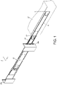
FIG. 1 is a three-dimensional diagram showing a slide rail assembly applicable to a rack and including a first rail, a second rail and a third rail according to an embodiment of the present invention; -
FIG. 2 is an exploded diagram showing the slide rail assembly according to the embodiment of the present invention; -
FIG. 3 is a three-dimensional diagram showing a second rail in a first view angle according to the embodiment of the present invention; -
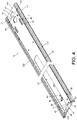
FIG. 4 is a three-dimensional diagram showing the second rail in a second view angle and an operation member at a position according to the embodiment of the present invention; -
FIG. 5 is a three-dimensional diagram showing the second rail in the second view angle and the operation member at another position according to the embodiment of the present invention; -
FIG. 6 is a schematic diagram showing the slide rail assembly applied to an environment with limited space and the slide rail assembly in an extending state according to the embodiment of the present invention; -
FIG. 7 is an enlarged view of a region A ofFIG. 6 ; -
FIG. 8 is a schematic diagram showing the slide rail assembly applied to the environment with limited space and the slide rail assembly in the extending state according to the embodiment of the present invention; -
FIG. 9 is an enlarged view of a region A ofFIG. 8 ; -
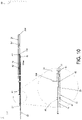
FIG. 10 is a schematic diagram showing the slide rail assembly applied to the environment with limited space and a third rail of the slide rail assembly capable of being displaced relative to the first rail along a retracting direction through the second rail according to the embodiment of the present invention; -
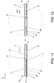
FIG. 11 is a schematic diagram showing the second rail of the slide rail assembly capable of being continuously displaced relative to the first rail along the retracting direction according to the embodiment of the present invention; -
FIG. 12 is a schematic diagram showing the second rail of the slide rail assembly capable of being further displaced relative to the first rail along the retracting direction according to the embodiment of the present invention; -
FIG. 13 is a schematic diagram showing the slide rail assembly applied to the environment with limited space and the slide rail assembly in another extending state according to the embodiment of the present invention; -
FIG. 14 is a schematic diagram showing the slide rail assembly applied to the environment with limited space and the slide rail assembly in the another extending state to allow the third rail to be detached from the second rail along an opening direction according to the embodiment of the present invention; -
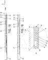
FIG. 15 is a schematic diagram showing the third rail of the slide rail assembly being remounted to the second rail along the retracting direction according to the embodiment of the present invention; -
FIG. 16 is a schematic diagram showing the third rail of the slide rail assembly being continuously displaced relative to the second rail along the retracting direction according to the embodiment of the present invention; -
FIG. 17 is a schematic diagram showing the slide rail assembly in another extending state and the operation member at the another position according to the embodiment of the present invention; and -
FIG. 18 is a schematic diagram showing the slide rail assembly in the another extending state and the operation member at the position according to the embodiment of the present invention. - As shown in
FIG. 1 , according to an embodiment of the present invention, a slide rail assembly includes afirst rail 22 and asecond rail 24. Preferably, the slide rail assembly can further include athird rail 26. Thesecond rail 24 is movably mounted between thefirst rail 22 and thethird rail 26. Thefirst rail 22 can be mounted to a rack (afirst post 25a and asecond post 25b thereof). Thethird rail 26 can be configured to carry a carriedobject 27. The first rail 22 (such as an outer rail), the second rail 24 (such as a middle rail) and the third rail 26 (such as an inner rail) are capable of longitudinally displacing relative to each other. The slide rail assembly is capable of in a fully extending state. Moreover, in the embodiment, the X-axis direction is a longitudinal direction (or a length direction or a displacement direction of a slide rail), the Y-axis direction is a transverse direction (or a lateral direction of the slide rail), and the Z-axis direction is a vertical direction (or a height direction of the slide rail) . Specifically, the X-axis direction can be a longitudinal direction of thefirst rail 22, and the Z-axis direction can be a height direction of thefirst rail 22. Each of thefirst rail 22, thesecond rail 24 and thethird rail 26 is a slide rail. - As shown in
FIG. 2 , thefirst rail 22 includes afirst wall 28a, asecond wall 28b and alongitudinal wall 30 connected between thefirst wall 28a and thesecond wall 28b of thefirst rail 22. Thefirst wall 28a, thesecond wall 28b and thelongitudinal wall 30 of thefirst rail 22 together define afirst passage 31. Thefirst passage 31 is for accommodating thesecond rail 24. Thefirst rail 22 includes a blockingmember 32 and apositioning member 34. At least one of the blockingmember 32 and the positioningmember 34 includes an elastic material. Herein, both of the blockingmember 32 and the positioningmember 34 are elastic components (such as elastic seats or spring leafs), which is only exemplary, and the present invention is not limited thereto. - Preferably, both of the blocking
member 32 and the positioningmember 34 are arranged at thelongitudinal wall 30 of thefirst rail 22. - Preferably, the blocking
member 32 includes afirst guiding portion 36a, asecond guiding portion 36b and a supportingstructure 38. An end of thefirst guiding portion 36a and an end of thesecond guiding portion 36b are connected to thelongitudinal wall 30 of thefirst rail 22. Both of thefirst guiding portion 36a and thesecond guiding portion 36b may exemplarily be inclined surfaces or curved surfaces. The supportingstructure 38 is located between thefirst guiding portion 36a and thesecond guiding portion 36b. The supportingstructure 38 includes a blockingsection 40, a guiding section 42 and alongitudinal section 44. Herein, the blockingsection 40 is a blocking wall (or an upright wall), which is only exemplary, and the present invention is not limited thereto. Thelongitudinal section 44 is located between the blockingsection 40 and the guiding section 42. The guiding section 42 may exemplarily be an inclined surface or a curved surface. Herein, the blockingmember 32 is exemplarily an elastic sheet structure, and protrudes from thelongitudinal wall 30 of thefirst rail 22 and faces toward thesecond rail 24. - Preferably, the positioning
member 34 includes apositioning portion 46. Herein, the positioningportion 46 is an edge wall of a space (such as a hole), which is only exemplary, and the present invention is not limited thereto. - Preferably, the positioning
member 34 further includes afirst guiding feature 48 and a second guiding feature 50, and thepositioning portion 46 is located between thefirst guiding feature 48 and the second guiding feature 50. Surfaces of thefirst guiding feature 48 and the second guiding feature 50 may exemplarily be inclined surfaces or curved surfaces. Herein, the positioningmember 34 is exemplarily an elastic sheet structure, and protrudes from thelongitudinal wall 30 of thefirst rail 22 and faces toward thesecond rail 24. - The blocking
member 32 and the positioningmember 34 are spaced by a distance along the X-axis direction, and the blockingmember 32 is closer to afront end portion 22a of thefirst rail 22 than the positioningmember 34. The blockingmember 32 and the positioningmember 34 are spaced by a distance along the Z-axis direction. - The
second rail 24 includes afirst wall 52a, asecond wall 52b and alongitudinal wall 54 connected between thefirst wall 52a and thesecond wall 52b of thesecond rail 24. Thefirst wall 52a, thesecond wall 52b and thelongitudinal wall 54 of thesecond rail 24 together define asecond passage 55. Thesecond passage 55 is for accommodating thethird rail 26. Thethird rail 26 includes afirst wall 56a, asecond wall 56b and alongitudinal wall 58 connected between thefirst wall 56a and thesecond wall 56b of thethird rail 26. - As shown in
FIG. 2 to FIG. 4 , thesecond rail 24 has a first side L1 and a second side L2 opposite to the first side L1. The first side L1 is adjacent to thefirst rail 22, and the second side L2 is adjacent to thethird rail 26. Thesecond rail 24 includes apredetermined feature 61. Thepredetermined feature 61 is configured to be cooperated with the positioningmember 34 of thefirst rail 22. - Preferably, the
predetermined feature 61 is a protrusion arranged on the first side L1 of thelongitudinal wall 54 of thesecond rail 24. Herein, thepredetermined feature 61 is a fixing pin connected to thelongitudinal wall 54 of thesecond rail 24, which is only exemplary, and the present disclosure in not limited thereto. For example, in other embodiment, thepredetermined feature 61 can be a protruding portion integrally formed on thelongitudinal wall 54 of thesecond rail 24. - Preferably, the slide rail assembly further includes a working
member 60 movably mounted to thesecond rail 24. Herein, the workingmember 60 is pivotally connected to the second side L2 of thelongitudinal wall 54 of thesecond rail 24 through ashaft member 62, which is only exemplary, and the present disclosure in not limited thereto. - Preferably, the slide rail assembly further includes an
elastic member 64 for providing an elastic force to the workingmember 60. - Preferably, the
longitudinal wall 54 of thesecond rail 24 has a throughhole 66 communicating the first side L1 and the second side L2 of thesecond rail 24. The workingmember 60 includes an extendingportion 68 passing through a portion of the throughhole 66 and protruding from the first side L1 of thesecond rail 24. The extendingportion 68 is configured to be cooperated with the blockingmember 32 of thefirst rail 22. - The slide rail assembly includes an
operation member 70 for operating the blockingmember 32 and the positioningmember 34. Theoperation member 70 is operably mounted to thesecond rail 24. For example, theoperation member 70 is movably mounted to the first side L1 of thelongitudinal wall 54 of thesecond rail 24. Theoperation member 70 includes anoperation portion 72, a drivingportion 74 and amiddle portion 76 connected between theoperation portion 72 and the drivingportion 74. - Preferably, the
operation portion 72 is adjacent to afront end portion 24a of thesecond rail 24, and the drivingportion 74 is adjacent to arear end portion 24b of thesecond rail 24. - Preferably, the
second rail 24 and theoperation member 70 have limiting features cooperated with each other, such that theoperation member 70 is capable of longitudinally moving relative to thesecond rail 24 within a limited range. Herein, thesecond rail 24 and theoperation member 70 are mounted to each other through at least one connectingmember 80 passing through a portion of at least oneelongated hole 78, which is only exemplary, and the present disclosure in not limited thereto. That is, in the embodiment, the limiting features of thesecond rail 24 and theoperation member 70 are the at least one connectingmember 80 and the at least oneelongated hole 78. - Preferably, a
first opening 82 is formed on thelongitudinal wall 54 of thesecond rail 24. Asecond opening 84 is formed on theoperation member 70. Thesecond opening 84 is corresponding to thefirst opening 82 and a size of thesecond opening 84 is less than a size of thefirst opening 82. Theoperation portion 72 is adjacent to thesecond opening 84. Thesecond opening 84 is adapted to be passed through by a finger of the user to allow the user to apply a force to theoperation portion 72, so as to drive theoperation member 70 to move. - Preferably, the driving
portion 74 of theoperation member 70 includes afirst driving section 86 and asecond driving section 88 located at different heights. Thefirst driving section 86 is for driving the blockingmember 32 to move elastically. Thesecond driving section 88 is for driving thepositioning member 34 to move elastically. - The height of the
first driving section 86 is corresponding to a height of the blockingmember 32. The height of thesecond driving section 88 is corresponding to a height of the positioningmember 34. - Preferably, the
operation member 70 further includes a first space S1 and a second space S2 communicating two sides of theoperation member 70. Thefirst driving section 86 is located behind the first space S1, and thesecond driving section 88 is located in front of the second space S2 (as shown inFIG. 4 ). - Preferably, the extending
portion 68 of the workingmember 60 extends to the first space S1 of the operation member 70(as shown inFIG. 4 ). - Preferably, at least one extending
hole 90 is formed on thelongitudinal wall 54 of thesecond rail 24 for communicating the first side L1 and the second side L2 of thesecond rail 24. Theoperation member 70 further includes at least oneauxiliary portion 92 passing through a portion of the at least one extendinghole 90 and stretching out from the second side L2 of thesecond rail 24. - As shown in
FIG. 4 andFIG. 5 , theoperation member 70 is capable of being operated to move between a first operation position P1 (as shown inFIG. 4 ) and a second operation position P2 (as shown inFIG. 5 ). For example, the user can apply a force F to theoperation member 70 to allow theoperation member 70 to move from the first operation position P1 to the second operation position P2. Alternatively, theoperation member 70 can be applied with another force to allow theoperation member 70 to return to the first operation position P1 from the second operation position P2. - Preferably, when the
operation member 70 is located at the first operation position P1 relative to thesecond rail 24, thepredetermined feature 61 of thesecond rail 24 is located inside the second space S2, and thepredetermined feature 61 of thesecond rail 24 and thesecond driving section 88 of theoperation member 70 are close to each other (as shown inFIG. 4 ). Alternatively, when theoperation member 70 is located at the second operation position P2 relative to thesecond rail 24, thepredetermined feature 61 of thesecond rail 24 is located outside the second space S2, and thepredetermined feature 61 of thesecond rail 24 and thesecond driving section 88 of theoperation member 70 are far away from each other (as shown inFIG. 5 ). - As shown in
FIG. 6 andFIG. 7 , the slide rail assembly is applied to an environment with limited space. When the slide rail assembly is in the fully extending state, thesecond rail 24 is at a first extending position E1 relative to thefirst rail 22, and thethird rail 26 is at an opening position K (as shown inFIG. 6 ) relative to thesecond rail 24. When thesecond rail 24 is at the first extending position E1 relative to thefirst rail 22, the slide rail assembly has a first length J1, and a first distance M1 is between thefront end portion 26a of thethird rail 26 and an object 93 (such as a door or an obstacle) . Because the first distance M1 is too short, thethird rail 26 is incapable of being detached from thesecond passage 55 of thesecond rail 24 along an opening direction D1. - When the
second rail 24 is at the first extending position E1 relative to thefirst rail 22, the blockingmember 32 of thefirst rail 22 is in a blocking state Q1 capable of blocking the working member 60 (i.e., blocking thesecond rail 24; as shown inFIG. 7 ), so as to prevent thesecond rail 24 from displacing from the first extending position E1 along a retracting direction D2. Specifically, when the blockingmember 32 is in the blocking state Q1, a top surface of the supportingstructure 38 of the blockingmember 32 and a surface of thelongitudinal wall 30 of thefirst rail 22 together form a lateral height h1, and the blockingsection 40 of the supportingstructure 38 is capable of blocking the extendingportion 68 of the working member 60 (as shown inFIG. 7 ), so as to prevent thesecond rail 24 from displacing from the first extending position E1 along the retracting direction D2. Wherein, theoperation member 70 is at the first operation position P1 relative to thesecond rail 24, and thefirst driving section 86 of theoperation member 70 is adjacent to thefirst guiding portion 36a of the blockingmember 32. - As shown in
FIG. 8 andFIG. 9 , with theoperation member 70 being operably moved from the first operation position P1 to the second operation position P2, the blockingmember 32 is driven to leave the blocking state Q1 (For example, the blockingmember 32 is in an unblocking state Q2), such that the blockingmember 32 is incapable of blocking the workingmember 60 so as to allow thesecond rail 24 to displace from the first extending position E1 along the retracting direction D2. Specifically, when theoperation member 70 is moved from the first operation position P1 to the second operation position P2, theoperation member 70 pushes thefirst guiding portion 36a of the blockingmember 32 through thefirst driving section 86, such that the blockingmember 32 is moved transversely (laterally) from the blocking state Q1 to the unblocking state Q2 (as shown inFIG. 9 ). When the blockingmember 32 is in the unblocking state Q2, the top surface of the supportingstructure 38 of the blockingmember 32 and the surface of thelongitudinal wall 30 of thefirst rail 22 together form a height which is less that the lateral height h1, and the blockingsection 40 of the supportingstructure 38 is staggered from the extendingportion 68 of the workingmember 60, such that the blockingsection 40 of the supportingstructure 38 is incapable of blocking the extendingportion 68 of the working member 60 (as shown inFIG. 9 ) to allow thesecond rail 24 to displace from the first extending position E1 along the retracting direction D2. In other words, when the blockingmember 32 is pushed toward thelongitudinal wall 30 of thefirst rail 22 by thefirst driving section 86, the blockingmember 32 is changed from the blocking state Q1 to the unblocking state Q2. Moreover, when theoperation member 70 is moved from the first operation position P1 to the second operation position P2, theoperation member 70 is moved relative to thesecond rail 24 along the opening direction D1. - As shown in
FIG. 10 to FIG. 13 , when thesecond rail 24 is displaced relative to thefirst rail 22 from the first extending position E1 to a second extending position E2 along the retracting direction D2 (as shown inFIG. 12 andFIG. 13 ), thesecond rail 24 is engaged with the positioningmember 34 through thepredetermined feature 61 so as to prevent thesecond rail 24 from leaving the second extending position E2. - Specifically, during a process that the
second rail 24 is displaced from the first extending position E1 to the second extending position E2 along the retracting direction D2, thesecond rail 24 contacts thefirst guiding feature 48 of the positioningmember 34 through thepredetermined feature 61 to drive the positioningmember 34 to move from a first predetermined state W1 (as shown inFIG. 10 ) to a second predetermined state W2, such that the positioningmember 34 accumulates an elastic force F' (as shown inFIG. 11 ). When thesecond rail 24 reaches the second extending position E2, the positioningmember 34 returns from the second predetermined state W2 to the first predetermined state W1 (as shown inFIG. 12 ) in response to the release of the elastic force F', such that the positioningmember 34 is engaged with thepredetermined feature 61 through thepositioning portion 46 so as to prevent thesecond rail 24 from leaving the second extending position E2 (as shown inFIG. 12 andFIG. 13 ). More specifically, when the positioningmember 34 is in the first predetermined state W1, the positioningmember 34 blocks a front end and a rear end of thepredetermined feature 61 through afirst wall 46a and asecond wall 46b of thepositioning portion 46, respectively. As such, thesecond rail 24 is incapable of displacing from the second extending position E2 along the opening direction D1 or the retracting direction D2 (as shown inFIG. 12 andFIG. 13 ). In other words, when the positioningmember 34 is pushed toward thelongitudinal wall 30 of thefirst rail 22 by thepredetermined feature 61, the positioningmember 34 is changed from the first predetermined state W1 to the second predetermined state W2. - As shown in
FIG. 13 and FIG. 14 , when thesecond rail 24 is at the second extending position E2 relative to thefirst rail 22, the slide rail assembly has a second length J2 less than the first length J1, such that a second distance M2 which is larger than the first distance M1 (as shown inFIG. 6 ) is between thefront end portion 26a of thethird rail 26 and theobject 93. Accordingly, it is favorable for thethird rail 26 to be displaced along the opening direction D1 so as to be detached from thesecond passage 55 of the second rail 24 (as shown inFIG. 14 ). - As shown in
FIG. 2 andFIG. 14 toFIG. 16 , a contacting portion 94 (such as a protrusion, which is only exemplary) is arranged on thelongitudinal wall 58 of thethird rail 26 for being cooperated with the at least oneauxiliary portion 92 of theoperation member 70. - When the
second rail 24 is desired to be displaced relative to thefirst rail 22 from the second extending position E2 to a retracting position (such as a fully retracting position) along the retracting direction D2, thethird rail 26 can be reinserted into thesecond passage 55 of the second rail 24 (as shown inFIG. 15 ) from an outside of thesecond passage 55 of the second rail 24 (as shown inFIG. 14 ). During the process, thethird rail 26 is capable of contacting theauxiliary portion 92 of theoperation member 70 through the contactingportion 94 to drive theoperation member 70 to move relative to thesecond rail 24 from the second operation position P2 (as shown inFIG. 14 andFIG.15 ) to the first operation position P1 (as shown inFIG. 16 ), such that thesecond driving section 88 of theoperation member 70 contacts thefirst guiding feature 48 of the positioningmember 34 to drive the positioningmember 34. That is, the positioningmember 34 originally has a predetermined height h2 relative to thelongitudinal wall 30 of the first rail 22 (as shown inFIG. 10 ). The positioningmember 34 is pushed by thesecond driving section 88 of theoperation member 70, such that the predetermined height h2 is decreased or the positioningmember 34 is pushed to abut against thelongitudinal wall 30 of thefirst rail 22. As such, the positioningmember 34 is no longer in the first predetermined state W1 (For example, the positioningmember 34 is now in the second predetermined state W2 shown inFIG. 16 ), and thepositioning portion 46 of the positioningmember 34 is no longer engaged with thepredetermined feature 61, which allows thesecond rail 24 to displace from the second extending position E2 along the retracting direction D2, or allows thesecond rail 24 to displace from the second extending position E2 along the opening direction D1. When theoperation member 70 is moved from the second operation position P2 to the first operation position P1, theoperation member 70 is moved relative to thesecond rail 24 along the retracting direction D2. - As shown in
FIG. 17 and FIG. 18 , when thesecond rail 24 is at the second extending position E2 relative to thefirst rail 22, the engagement relationship between thesecond rail 24 and thefirst rail 22 not only can be disengaged through the third rail 26 (as shown inFIG. 16 ) but also can be disengaged by the user directly operating theoperation member 70. Specifically, through theoperation member 70 being operably moved from the second operation position P2 to the first operation position P1, the positioningmember 34 can be driven to leave the first predetermined state W1 (for example, the positioningmember 34 is in the second predetermined state W2 as shown inFIG. 18 ), such that thepositioning portion 46 of the positioningmember 34 is no longer engaged with thepredetermined feature 61 and the positioningmember 34 is incapable of blocking thesecond rail 24 so as to allow thesecond rail 24 to displace from the second extending position E2 along the retracting direction D2 or to allow thesecond rail 24 to displace from the second extending position E2 along the opening direction D1. - Moreover, during the process that the
second rail 24 is displaced from the retracting position (such as the fully retracing position) to the first extending position E1 along the opening direction D1, the extendingportion 68 of the workingmember 60 is capable of moving along the guiding section 42 and thelongitudinal section 44 of blockingmember 32 of thefirst rail 22 so as to be guided to the blocking section 40 (which can refer toFIG. 2 ), such that the blockingsection 40 of the blockingmember 32 is capable of blocking the extendingportion 68 of the workingmember 60 so as to prevent thesecond rail 24 to displace relative to thefirst rail 22 from the first extending position E1 along the retracting direction D2 (as shown inFIG. 6 andFIG. 7 ), which is well known in the art and is not described in detail for the sake of conciseness. - To sum up, the slide rail assembly according to the embodiment of the present invention includes the following features.
- First, the blocking relationship between the
second rail 24 and thefirst rail 22 is capable of being released through the operatingmember 70 operating the blockingmember 32 or the positioningmember 34, such that thesecond rail 24 is allowed to displace relative to thefirst rail 22 from an extending position (such as the first extending position E1 or the second extending position E2) along the retracting direction D2. - Second, when the
second rail 24 is displaced relative to thefirst rail 22 from the first extending position E1 to the second extending position E2 along the retracting direction D2, thesecond rail 24 is engaged with the positioningmember 34 through thepredetermined feature 61 so as to prevent thesecond rail 24 from leaving the second extending position E2. With theoperation member 70 being operably moved from an operation position to another operation position to drive the positioningmember 34, thepredetermined feature 61 is allowed to disengage from the positioningmember 34 so as to allow thesecond rail 24 to displace from the second extending position E2.
Claims (15)
- A slide rail assembly, comprising:a first rail (22) comprising a positioning member (34);a second rail (24) capable of displacing relative to the first rail (22), the second rail (24) comprising a predetermined feature (61); andan operation member (70);characterized in that when the second rail (24) is displaced relative to the first rail (22) from a first extending position (E1) to a second extending position (E2) along a retracting direction (D2), the second rail (24) is engaged with the positioning member (34) through the predetermined feature (61) so as to prevent the second rail (24) from leaving the second extending position (E2);wherein the positioning member (34) is driven through the operation member (70) being operably moved from a second operation position (P2) to a first operation position (PI), such that the predetermined feature (61) is no longer engaged with the positioning member (34) so as to allow the second rail (24) to leave the second extending position (E2).
- The slide rail assembly of claim 1, characterized in that:the first rail (22) further comprises a blocking member (32);when the second rail (24) is at the first extending position (E1) relative to the first rail (22), the blocking member (32) is for blocking the second rail (24) so as to prevent the second rail (24) from displacing from the first extending position (E1) along the retracting direction (D2);the blocking member (32) is driven through the operation member (70) being operably moved from the first operation position (P1) to the second operation position (P2), such that the blocking member (32) is incapable of blocking the second rail (24) so as to allow the second rail (24) to displace from the first extending position (E1) along the retracting direction (D2) .
- The slide rail assembly of claim 2, further characterized by:a working member (60) mounted to the second rail (24);wherein when the second rail (24) is at the first extending position (E1) relative to the first rail (22), the blocking member (32) is in a blocking state (Q1) capable of blocking the working member (60) so as to prevent the second rail (24) from displacing from the first extending position (E1) along the retracting direction (D2);wherein the operation member (70) is capable of being operated to move from the first operation position (P1) to the second operation position (P2) to drive the blocking member (32) to leave the blocking state (Q1), such that the blocking member (32) is incapable of blocking the working member (60) so as to allow the second rail (24) to displace from the first extending position (E1) along the retracting direction (D2) .
- The slide rail assembly of claim 3, characterized in that the working member (60) is movably mounted to the second rail (24), and the slide rail assembly further comprises an elastic member (64) for providing an elastic force to the working member (60) .
- The slide rail assembly of any of claims 2-4, characterized in that each of the blocking member (32) and positioning member (34) comprises an elastic material.
- The slide rail assembly of claim 5, characterized in that each of the blocking member (32) and positioning member (34) is an elastic sheet structure, and protrudes from a longitudinal wall (30) of the first rail (22) and faces toward the second rail (24) .
- The slide rail assembly of claim 5 or 6, characterized in that:the positioning member (34) comprises a positioning portion (46) ;during a process that the second rail (24) is displaced from the first extending position (E1) to the second extending position (E2) along the retracting direction (D2), the second rail (24) drives the positioning member (34) to move from a first predetermined state (W1) to a second predetermined state (W2) through the predetermined feature (61), such that the positioning member (34) accumulates an elastic force;when the second rail (24) reaches the second extending position (E2), the positioning member (34) returns from the second predetermined state (W2) to the first predetermined state (W1) in response to the release of the elastic force, such that the positioning member (34) is engaged with the predetermined feature (61) through the positioning portion (46) so as to prevent the second rail (24) from leaving the second extending position (E2).
- The slide rail assembly of claim 7, characterized in that the positioning member (34) is driven to leave the first predetermined state (W1) through the operation member (70) being operably moved from the second operation position (P2) to the first operation position (PI), such that the positioning portion (46) of the positioning member (34) is no longer engaged with the predetermined feature (61) so as to allow the second rail (24) to displace from the second extending position (E2) along the retracting direction (D2).
- The slide rail assembly of claim 7, further characterized by:
a third rail (26), wherein the second rail (24) is movably mounted between the first rail (22) and the third rail (26). - The slide rail assembly of claim 9, characterized in that when the second rail (24) is at the second extending position (E2), the third rail (26) is capable of being displaced relative to the second rail (24) along an opening direction (D1) so as to be detached from a passage (55) of the second rail (24).
- The slide rail assembly of claim 10, characterized in that when the third rail (26) is reinserted into the passage (55) of the second rail (24) from an outside of the passage (55) of the second rail (24) along the retracting direction (D2), the third rail (26) drives the operation member (70) to move relative to the second rail (24) from the second operation position (P2) to the first operation position (P1) to drive the positioning member (34) to leave the first predetermined state (W1), such that the positioning portion (46) of the positioning member (34) is no longer engaged with the predetermined feature (61) so as to allow the second rail (24) to displace from the second extending position (E2) along the retracting direction (D2).
- The slide rail assembly of any of claims 5-11, characterized in that the slide rail assembly defines an X-axis direction and a Z-axis direction, the X-axis direction is a longitudinal direction of the first rail (22), the Z-axis direction is a height direction of the first rail (22), the blocking member (32) and the positioning member (34) are spaced by a distance along the X-axis direction, the blocking member (32) is closer to a front end portion (22a) of the first rail (22) than the positioning member (34), the blocking member (32) and the positioning member (34) are spaced by a distance along the Z-axis direction.
- The slide rail assembly of claim 12, characterized in that the operation member (70) comprises a driving portion (74) adjacent to a rear end portion (24b) of the second rail (24), the driving portion (74) comprises a first driving section (86) and a second driving section (88) located at different heights in the Z-axis direction, the first driving section (86) is for driving the blocking member (32) to move elastically, and the second driving section (88) is for driving the positioning member (34) to move elastically.
- The slide rail assembly of any of claims 1-13, characterized in that when the operation member (70) is moved from the second operation position (P2) to the first operation position (P1), the operation member (70) is moved relative to the second rail (24) along the retracting direction (D2).
- The slide rail assembly of any of claims 1-14, characterized in that when the second rail (24) is at the first extending position (E1) relative to the first rail (22), the slide rail assembly has a first length (J1), when the second rail (24) is at the second extending position (E2) relative to the first rail (22), the slide rail assembly has a second length less (J2) than the first length (J1) .
Applications Claiming Priority (1)
| Application Number | Priority Date | Filing Date | Title |
|---|---|---|---|
| TW109147232A TWI750987B (en) | 2020-12-30 | 2020-12-30 | Slide rail assembly |
Publications (2)
| Publication Number | Publication Date |
|---|---|
| EP4023108A1 true EP4023108A1 (en) | 2022-07-06 |
| EP4023108B1 EP4023108B1 (en) | 2024-11-20 |
Family
ID=76011776
Family Applications (1)
| Application Number | Title | Priority Date | Filing Date |
|---|---|---|---|
| EP21174641.7A Active EP4023108B1 (en) | 2020-12-30 | 2021-05-19 | Slide rail assembly |
Country Status (4)
| Country | Link |
|---|---|
| US (1) | US11406187B2 (en) |
| EP (1) | EP4023108B1 (en) |
| JP (1) | JP7083064B1 (en) |
| TW (1) | TWI750987B (en) |
Families Citing this family (4)
| Publication number | Priority date | Publication date | Assignee | Title |
|---|---|---|---|---|
| JP2024130231A (en) * | 2023-03-14 | 2024-09-30 | 京セラドキュメントソリューションズ株式会社 | Slide rail and image forming apparatus |
| TWI829614B (en) | 2023-08-04 | 2024-01-11 | 川湖科技股份有限公司 | Slide rail assembly |
| TWI850157B (en) * | 2023-11-21 | 2024-07-21 | 川湖科技股份有限公司 | Fitting assembly and fitting device thereof |
| US20260129782A1 (en) * | 2024-11-04 | 2026-05-07 | Fositek Corporation | Slide rail device for a server case |
Citations (6)
| Publication number | Priority date | Publication date | Assignee | Title |
|---|---|---|---|---|
| US9681749B2 (en) | 2015-04-13 | 2017-06-20 | King Slide Works Co., Ltd. | Slide rail assembly |
| US10041535B2 (en) | 2016-07-29 | 2018-08-07 | King Slide Works Co., Ltd. | Slide rail assembly |
| US10413065B2 (en) * | 2017-12-28 | 2019-09-17 | King Slide Works Co., Ltd. | Slide rail assembly and rail kit thereof |
| US10716398B1 (en) * | 2019-05-06 | 2020-07-21 | King Slide Works Co., Ltd. | Slide rail assembly |
| TWI704889B (en) * | 2019-10-28 | 2020-09-21 | 川湖科技股份有限公司 | Slide rail assembly |
| TWI706749B (en) * | 2019-11-18 | 2020-10-11 | 川湖科技股份有限公司 | Slide rail assembly |
Family Cites Families (24)
| Publication number | Priority date | Publication date | Assignee | Title |
|---|---|---|---|---|
| TW521603U (en) | 2001-08-08 | 2003-02-21 | Jiun-Lung Yang | Imporvement of positioning structure of rail for keyboard drawer of detachable computer desk |
| US6402275B1 (en) | 2001-09-25 | 2002-06-11 | Jun-Long Yang | Detachable drawer rail |
| US6899408B2 (en) | 2003-04-15 | 2005-05-31 | King Slide Works Co., Ltd. | Track device for a drawer |
| JP3097862U (en) | 2003-05-16 | 2004-02-12 | 川湖工廠股▲分▼有限公司 | Drawer truck positioning structure |
| US7404611B1 (en) * | 2003-07-09 | 2008-07-29 | Central Industrial Supply Company | Pin and torsion spring lock for a drawer slide |
| US8585164B2 (en) * | 2011-06-02 | 2013-11-19 | King Slide Works Co., Ltd. | Locking mechanism of slide assembly |
| JP3177386U (en) | 2012-05-19 | 2012-08-02 | 宜瑪工業股▲ふん▼有限公司 | Slide rail for two-way drawer and its drawer set |
| US8733864B2 (en) | 2012-08-08 | 2014-05-27 | E-Make Co., Ltd. | Two way drawer slide |
| TWI593341B (en) * | 2015-09-18 | 2017-07-21 | King Slide Works Co | Slide rail assembly |
| TWI568382B (en) * | 2016-01-22 | 2017-02-01 | 川湖科技股份有限公司 | Slide rail assembly and operation method thereof |
| TWI584761B (en) * | 2016-09-13 | 2017-06-01 | 川湖科技股份有限公司 | Slide rail assembly |
| TWI665983B (en) * | 2017-04-12 | 2019-07-21 | 川湖科技股份有限公司 | Slide rail assembly |
| TWI629956B (en) * | 2017-05-04 | 2018-07-21 | 川湖科技股份有限公司 | Slide rail assembly |
| TWI646924B (en) * | 2017-09-20 | 2019-01-11 | 振躍精密滑軌股份有限公司 | Slide rail device with middle rail unlocking function |
| US10499738B2 (en) | 2017-12-28 | 2019-12-10 | King Slide Works Co., Ltd. | Slide rail assembly |
| TWI670029B (en) * | 2018-03-08 | 2019-09-01 | 川湖科技股份有限公司 | Slide rail assembly |
| TWI693044B (en) * | 2018-07-27 | 2020-05-11 | 川湖科技股份有限公司 | Slide rail assembly |
| US10736422B2 (en) | 2018-10-04 | 2020-08-11 | King Slide Works Co., Ltd. | Slide rail assembly |
| TWI676438B (en) * | 2018-10-25 | 2019-11-11 | 川湖科技股份有限公司 | Slide rail assembly |
| TWI699176B (en) | 2019-05-27 | 2020-07-21 | 川湖科技股份有限公司 | Synchronization system, device and method for slide rail assembly |
| TWI700057B (en) * | 2019-06-12 | 2020-08-01 | 川湖科技股份有限公司 | Slide rail assembly and operation method thereof |
| TWI700056B (en) * | 2019-06-12 | 2020-08-01 | 川湖科技股份有限公司 | Slide rail assembly |
| TWI706751B (en) * | 2019-08-14 | 2020-10-11 | 川湖科技股份有限公司 | Slide rail assembly |
| TWI706752B (en) * | 2019-11-18 | 2020-10-11 | 川湖科技股份有限公司 | Slide rail assembly |
-
2020
- 2020-12-30 TW TW109147232A patent/TWI750987B/en active
-
2021
- 2021-03-22 US US17/207,758 patent/US11406187B2/en active Active
- 2021-05-19 EP EP21174641.7A patent/EP4023108B1/en active Active
- 2021-06-11 JP JP2021097744A patent/JP7083064B1/en active Active
Patent Citations (6)
| Publication number | Priority date | Publication date | Assignee | Title |
|---|---|---|---|---|
| US9681749B2 (en) | 2015-04-13 | 2017-06-20 | King Slide Works Co., Ltd. | Slide rail assembly |
| US10041535B2 (en) | 2016-07-29 | 2018-08-07 | King Slide Works Co., Ltd. | Slide rail assembly |
| US10413065B2 (en) * | 2017-12-28 | 2019-09-17 | King Slide Works Co., Ltd. | Slide rail assembly and rail kit thereof |
| US10716398B1 (en) * | 2019-05-06 | 2020-07-21 | King Slide Works Co., Ltd. | Slide rail assembly |
| TWI704889B (en) * | 2019-10-28 | 2020-09-21 | 川湖科技股份有限公司 | Slide rail assembly |
| TWI706749B (en) * | 2019-11-18 | 2020-10-11 | 川湖科技股份有限公司 | Slide rail assembly |
Also Published As
| Publication number | Publication date |
|---|---|
| US11406187B2 (en) | 2022-08-09 |
| JP2022104858A (en) | 2022-07-12 |
| JP7083064B1 (en) | 2022-06-09 |
| TWI750987B (en) | 2021-12-21 |
| EP4023108B1 (en) | 2024-11-20 |
| TW202224600A (en) | 2022-07-01 |
| US20220202181A1 (en) | 2022-06-30 |
Similar Documents
| Publication | Publication Date | Title |
|---|---|---|
| EP4023108B1 (en) | Slide rail assembly | |
| TWI704889B (en) | Slide rail assembly | |
| TWI706752B (en) | Slide rail assembly | |
| EP3068199A2 (en) | Slide rail assembly | |
| TWI706749B (en) | Slide rail assembly | |
| EP3735859B1 (en) | Slide rail assembly | |
| TWI706751B (en) | Slide rail assembly | |
| EP3461244B1 (en) | Slide rail assembly and driving mechanism thereof | |
| EP3387950A1 (en) | Slide rail assembly | |
| EP3960031B1 (en) | Slide rail assembly | |
| JP7772397B2 (en) | Slide rail assembly | |
| EP3387951B1 (en) | Clutch system for furniture parts | |
| JP7647004B2 (en) | Furniture Assembly | |
| CN114711572B (en) | Sliding rail assembly | |
| CN112754197B (en) | Slide rail assembly | |
| US20240360870A1 (en) | Slide rail assembly | |
| JP6295179B2 (en) | Travel guide device | |
| EP4736711A1 (en) | Slide rail assembly | |
| CN112386025A (en) | Sliding rail assembly | |
| CN111839038A (en) | Sliding rail assembly | |
| JP2026079670A (en) | Slide rail assembly | |
| JP2025184762A (en) | Slide rail assembly | |
| JP2024152049A (en) | Trigger part positioning jig | |
| CN119145718A (en) | Furniture assembly and interlink lock kit thereof |
Legal Events
| Date | Code | Title | Description |
|---|---|---|---|
| PUAI | Public reference made under article 153(3) epc to a published international application that has entered the european phase |
Free format text: ORIGINAL CODE: 0009012 |
|
| STAA | Information on the status of an ep patent application or granted ep patent |
Free format text: STATUS: REQUEST FOR EXAMINATION WAS MADE |
|
| 17P | Request for examination filed |
Effective date: 20220209 |
|
| AK | Designated contracting states |
Kind code of ref document: A1 Designated state(s): AL AT BE BG CH CY CZ DE DK EE ES FI FR GB GR HR HU IE IS IT LI LT LU LV MC MK MT NL NO PL PT RO RS SE SI SK SM TR |
|
| STAA | Information on the status of an ep patent application or granted ep patent |
Free format text: STATUS: EXAMINATION IS IN PROGRESS |
|
| 17Q | First examination report despatched |
Effective date: 20230720 |
|
| GRAP | Despatch of communication of intention to grant a patent |
Free format text: ORIGINAL CODE: EPIDOSNIGR1 |
|
| STAA | Information on the status of an ep patent application or granted ep patent |
Free format text: STATUS: GRANT OF PATENT IS INTENDED |
|
| INTG | Intention to grant announced |
Effective date: 20240625 |
|
| RIN1 | Information on inventor provided before grant (corrected) |
Inventor name: WANG, CHUN-CHIANG Inventor name: WENG, TZU-CHENG Inventor name: YANG, SHUN-HO Inventor name: CHEN, KEN-CHING |
|
| GRAS | Grant fee paid |
Free format text: ORIGINAL CODE: EPIDOSNIGR3 |
|
| GRAA | (expected) grant |
Free format text: ORIGINAL CODE: 0009210 |
|
| STAA | Information on the status of an ep patent application or granted ep patent |
Free format text: STATUS: THE PATENT HAS BEEN GRANTED |
|
| AK | Designated contracting states |
Kind code of ref document: B1 Designated state(s): AL AT BE BG CH CY CZ DE DK EE ES FI FR GB GR HR HU IE IS IT LI LT LU LV MC MK MT NL NO PL PT RO RS SE SI SK SM TR |
|
| REG | Reference to a national code |
Ref country code: GB Ref legal event code: FG4D |
|
| REG | Reference to a national code |
Ref country code: CH Ref legal event code: EP |
|
| REG | Reference to a national code |
Ref country code: DE Ref legal event code: R096 Ref document number: 602021021978 Country of ref document: DE |
|
| REG | Reference to a national code |
Ref country code: IE Ref legal event code: FG4D |
|
| REG | Reference to a national code |
Ref country code: LT Ref legal event code: MG9D |
|
| REG | Reference to a national code |
Ref country code: NL Ref legal event code: MP Effective date: 20241120 |
|
| PG25 | Lapsed in a contracting state [announced via postgrant information from national office to epo] |
Ref country code: IS Free format text: LAPSE BECAUSE OF FAILURE TO SUBMIT A TRANSLATION OF THE DESCRIPTION OR TO PAY THE FEE WITHIN THE PRESCRIBED TIME-LIMIT Effective date: 20250320 Ref country code: PT Free format text: LAPSE BECAUSE OF FAILURE TO SUBMIT A TRANSLATION OF THE DESCRIPTION OR TO PAY THE FEE WITHIN THE PRESCRIBED TIME-LIMIT Effective date: 20250320 Ref country code: HR Free format text: LAPSE BECAUSE OF FAILURE TO SUBMIT A TRANSLATION OF THE DESCRIPTION OR TO PAY THE FEE WITHIN THE PRESCRIBED TIME-LIMIT Effective date: 20241120 |
|
| PG25 | Lapsed in a contracting state [announced via postgrant information from national office to epo] |
Ref country code: FI Free format text: LAPSE BECAUSE OF FAILURE TO SUBMIT A TRANSLATION OF THE DESCRIPTION OR TO PAY THE FEE WITHIN THE PRESCRIBED TIME-LIMIT Effective date: 20241120 Ref country code: NL Free format text: LAPSE BECAUSE OF FAILURE TO SUBMIT A TRANSLATION OF THE DESCRIPTION OR TO PAY THE FEE WITHIN THE PRESCRIBED TIME-LIMIT Effective date: 20241120 |
|
| REG | Reference to a national code |
Ref country code: AT Ref legal event code: MK05 Ref document number: 1742749 Country of ref document: AT Kind code of ref document: T Effective date: 20241120 |
|
| PG25 | Lapsed in a contracting state [announced via postgrant information from national office to epo] |
Ref country code: BG Free format text: LAPSE BECAUSE OF FAILURE TO SUBMIT A TRANSLATION OF THE DESCRIPTION OR TO PAY THE FEE WITHIN THE PRESCRIBED TIME-LIMIT Effective date: 20241120 |
|
| PG25 | Lapsed in a contracting state [announced via postgrant information from national office to epo] |
Ref country code: ES Free format text: LAPSE BECAUSE OF FAILURE TO SUBMIT A TRANSLATION OF THE DESCRIPTION OR TO PAY THE FEE WITHIN THE PRESCRIBED TIME-LIMIT Effective date: 20241120 |
|
| PG25 | Lapsed in a contracting state [announced via postgrant information from national office to epo] |
Ref country code: NO Free format text: LAPSE BECAUSE OF FAILURE TO SUBMIT A TRANSLATION OF THE DESCRIPTION OR TO PAY THE FEE WITHIN THE PRESCRIBED TIME-LIMIT Effective date: 20250220 |
|
| PG25 | Lapsed in a contracting state [announced via postgrant information from national office to epo] |
Ref country code: LV Free format text: LAPSE BECAUSE OF FAILURE TO SUBMIT A TRANSLATION OF THE DESCRIPTION OR TO PAY THE FEE WITHIN THE PRESCRIBED TIME-LIMIT Effective date: 20241120 Ref country code: GR Free format text: LAPSE BECAUSE OF FAILURE TO SUBMIT A TRANSLATION OF THE DESCRIPTION OR TO PAY THE FEE WITHIN THE PRESCRIBED TIME-LIMIT Effective date: 20250221 Ref country code: AT Free format text: LAPSE BECAUSE OF FAILURE TO SUBMIT A TRANSLATION OF THE DESCRIPTION OR TO PAY THE FEE WITHIN THE PRESCRIBED TIME-LIMIT Effective date: 20241120 |
|
| PG25 | Lapsed in a contracting state [announced via postgrant information from national office to epo] |
Ref country code: PL Free format text: LAPSE BECAUSE OF FAILURE TO SUBMIT A TRANSLATION OF THE DESCRIPTION OR TO PAY THE FEE WITHIN THE PRESCRIBED TIME-LIMIT Effective date: 20241120 |
|
| PG25 | Lapsed in a contracting state [announced via postgrant information from national office to epo] |
Ref country code: RS Free format text: LAPSE BECAUSE OF FAILURE TO SUBMIT A TRANSLATION OF THE DESCRIPTION OR TO PAY THE FEE WITHIN THE PRESCRIBED TIME-LIMIT Effective date: 20250220 |
|
| PG25 | Lapsed in a contracting state [announced via postgrant information from national office to epo] |
Ref country code: SM Free format text: LAPSE BECAUSE OF FAILURE TO SUBMIT A TRANSLATION OF THE DESCRIPTION OR TO PAY THE FEE WITHIN THE PRESCRIBED TIME-LIMIT Effective date: 20241120 |
|
| PGFP | Annual fee paid to national office [announced via postgrant information from national office to epo] |
Ref country code: DE Payment date: 20250512 Year of fee payment: 5 |
|
| PG25 | Lapsed in a contracting state [announced via postgrant information from national office to epo] |
Ref country code: DK Free format text: LAPSE BECAUSE OF FAILURE TO SUBMIT A TRANSLATION OF THE DESCRIPTION OR TO PAY THE FEE WITHIN THE PRESCRIBED TIME-LIMIT Effective date: 20241120 |
|
| PG25 | Lapsed in a contracting state [announced via postgrant information from national office to epo] |
Ref country code: EE Free format text: LAPSE BECAUSE OF FAILURE TO SUBMIT A TRANSLATION OF THE DESCRIPTION OR TO PAY THE FEE WITHIN THE PRESCRIBED TIME-LIMIT Effective date: 20241120 |
|
| PG25 | Lapsed in a contracting state [announced via postgrant information from national office to epo] |
Ref country code: RO Free format text: LAPSE BECAUSE OF FAILURE TO SUBMIT A TRANSLATION OF THE DESCRIPTION OR TO PAY THE FEE WITHIN THE PRESCRIBED TIME-LIMIT Effective date: 20241120 |
|
| PG25 | Lapsed in a contracting state [announced via postgrant information from national office to epo] |
Ref country code: SK Free format text: LAPSE BECAUSE OF FAILURE TO SUBMIT A TRANSLATION OF THE DESCRIPTION OR TO PAY THE FEE WITHIN THE PRESCRIBED TIME-LIMIT Effective date: 20241120 |
|
| PG25 | Lapsed in a contracting state [announced via postgrant information from national office to epo] |
Ref country code: CZ Free format text: LAPSE BECAUSE OF FAILURE TO SUBMIT A TRANSLATION OF THE DESCRIPTION OR TO PAY THE FEE WITHIN THE PRESCRIBED TIME-LIMIT Effective date: 20241120 |
|
| PG25 | Lapsed in a contracting state [announced via postgrant information from national office to epo] |
Ref country code: IT Free format text: LAPSE BECAUSE OF FAILURE TO SUBMIT A TRANSLATION OF THE DESCRIPTION OR TO PAY THE FEE WITHIN THE PRESCRIBED TIME-LIMIT Effective date: 20241120 |
|
| REG | Reference to a national code |
Ref country code: DE Ref legal event code: R097 Ref document number: 602021021978 Country of ref document: DE |
|
| PG25 | Lapsed in a contracting state [announced via postgrant information from national office to epo] |
Ref country code: SE Free format text: LAPSE BECAUSE OF FAILURE TO SUBMIT A TRANSLATION OF THE DESCRIPTION OR TO PAY THE FEE WITHIN THE PRESCRIBED TIME-LIMIT Effective date: 20241120 |
|
| PLBE | No opposition filed within time limit |
Free format text: ORIGINAL CODE: 0009261 |
|
| STAA | Information on the status of an ep patent application or granted ep patent |
Free format text: STATUS: NO OPPOSITION FILED WITHIN TIME LIMIT |
|
| 26N | No opposition filed |
Effective date: 20250821 |
|
| REG | Reference to a national code |
Ref country code: CH Ref legal event code: H13 Free format text: ST27 STATUS EVENT CODE: U-0-0-H10-H13 (AS PROVIDED BY THE NATIONAL OFFICE) Effective date: 20251223 |
|
| PG25 | Lapsed in a contracting state [announced via postgrant information from national office to epo] |
Ref country code: LU Free format text: LAPSE BECAUSE OF NON-PAYMENT OF DUE FEES Effective date: 20250519 |
|
| PG25 | Lapsed in a contracting state [announced via postgrant information from national office to epo] |
Ref country code: CH Free format text: LAPSE BECAUSE OF NON-PAYMENT OF DUE FEES Effective date: 20250531 |
|
| REG | Reference to a national code |
Ref country code: BE Ref legal event code: MM Effective date: 20250531 |
|
| PG25 | Lapsed in a contracting state [announced via postgrant information from national office to epo] |
Ref country code: MC Free format text: LAPSE BECAUSE OF FAILURE TO SUBMIT A TRANSLATION OF THE DESCRIPTION OR TO PAY THE FEE WITHIN THE PRESCRIBED TIME-LIMIT Effective date: 20241120 |
|
| PGFP | Annual fee paid to national office [announced via postgrant information from national office to epo] |
Ref country code: GB Payment date: 20260310 Year of fee payment: 6 |
|
| PGFP | Annual fee paid to national office [announced via postgrant information from national office to epo] |
Ref country code: IE Payment date: 20260306 Year of fee payment: 6 |
|
| PG25 | Lapsed in a contracting state [announced via postgrant information from national office to epo] |
Ref country code: BE Free format text: LAPSE BECAUSE OF NON-PAYMENT OF DUE FEES Effective date: 20250531 |
|
| PG25 | Lapsed in a contracting state [announced via postgrant information from national office to epo] |
Ref country code: FR Free format text: LAPSE BECAUSE OF NON-PAYMENT OF DUE FEES Effective date: 20250531 |