EP4022939B1 - Lautsprecherelement und lautsprecher mit einem solchen lautsprecherelement - Google Patents
Lautsprecherelement und lautsprecher mit einem solchen lautsprecherelement Download PDFInfo
- Publication number
- EP4022939B1 EP4022939B1 EP20767625.5A EP20767625A EP4022939B1 EP 4022939 B1 EP4022939 B1 EP 4022939B1 EP 20767625 A EP20767625 A EP 20767625A EP 4022939 B1 EP4022939 B1 EP 4022939B1
- Authority
- EP
- European Patent Office
- Prior art keywords
- speaker
- elements
- membrane
- planes
- wires
- Prior art date
- Legal status (The legal status is an assumption and is not a legal conclusion. Google has not performed a legal analysis and makes no representation as to the accuracy of the status listed.)
- Active
Links
Images


Classifications
-
- H—ELECTRICITY
- H04—ELECTRIC COMMUNICATION TECHNIQUE
- H04R—LOUDSPEAKERS, MICROPHONES, GRAMOPHONE PICK-UPS OR LIKE ACOUSTIC ELECTROMECHANICAL TRANSDUCERS; ELECTRIC HEARING AIDS; PUBLIC ADDRESS SYSTEMS
- H04R1/00—Details of transducers, loudspeakers or microphones
- H04R1/20—Arrangements for obtaining desired frequency or directional characteristics
- H04R1/22—Arrangements for obtaining desired frequency or directional characteristics for obtaining desired frequency characteristic only
- H04R1/24—Structural combinations of separate transducers or of two parts of the same transducer and responsive respectively to two or more frequency ranges
-
- H—ELECTRICITY
- H04—ELECTRIC COMMUNICATION TECHNIQUE
- H04R—LOUDSPEAKERS, MICROPHONES, GRAMOPHONE PICK-UPS OR LIKE ACOUSTIC ELECTROMECHANICAL TRANSDUCERS; ELECTRIC HEARING AIDS; PUBLIC ADDRESS SYSTEMS
- H04R9/00—Transducers of moving-coil, moving-strip, or moving-wire type
- H04R9/06—Loudspeakers
- H04R9/063—Loudspeakers using a plurality of acoustic drivers
-
- H—ELECTRICITY
- H04—ELECTRIC COMMUNICATION TECHNIQUE
- H04R—LOUDSPEAKERS, MICROPHONES, GRAMOPHONE PICK-UPS OR LIKE ACOUSTIC ELECTROMECHANICAL TRANSDUCERS; ELECTRIC HEARING AIDS; PUBLIC ADDRESS SYSTEMS
- H04R7/00—Diaphragms for electromechanical transducers; Cones
- H04R7/02—Diaphragms for electromechanical transducers; Cones characterised by the construction
- H04R7/04—Plane diaphragms
-
- H—ELECTRICITY
- H04—ELECTRIC COMMUNICATION TECHNIQUE
- H04R—LOUDSPEAKERS, MICROPHONES, GRAMOPHONE PICK-UPS OR LIKE ACOUSTIC ELECTROMECHANICAL TRANSDUCERS; ELECTRIC HEARING AIDS; PUBLIC ADDRESS SYSTEMS
- H04R9/00—Transducers of moving-coil, moving-strip, or moving-wire type
- H04R9/02—Details
-
- H—ELECTRICITY
- H04—ELECTRIC COMMUNICATION TECHNIQUE
- H04R—LOUDSPEAKERS, MICROPHONES, GRAMOPHONE PICK-UPS OR LIKE ACOUSTIC ELECTROMECHANICAL TRANSDUCERS; ELECTRIC HEARING AIDS; PUBLIC ADDRESS SYSTEMS
- H04R9/00—Transducers of moving-coil, moving-strip, or moving-wire type
- H04R9/02—Details
- H04R9/025—Magnetic circuit
-
- H—ELECTRICITY
- H04—ELECTRIC COMMUNICATION TECHNIQUE
- H04R—LOUDSPEAKERS, MICROPHONES, GRAMOPHONE PICK-UPS OR LIKE ACOUSTIC ELECTROMECHANICAL TRANSDUCERS; ELECTRIC HEARING AIDS; PUBLIC ADDRESS SYSTEMS
- H04R9/00—Transducers of moving-coil, moving-strip, or moving-wire type
- H04R9/02—Details
- H04R9/04—Construction, mounting, or centering of coil
- H04R9/046—Construction
- H04R9/047—Construction in which the windings of the moving coil lay in the same plane
-
- H—ELECTRICITY
- H04—ELECTRIC COMMUNICATION TECHNIQUE
- H04R—LOUDSPEAKERS, MICROPHONES, GRAMOPHONE PICK-UPS OR LIKE ACOUSTIC ELECTROMECHANICAL TRANSDUCERS; ELECTRIC HEARING AIDS; PUBLIC ADDRESS SYSTEMS
- H04R9/00—Transducers of moving-coil, moving-strip, or moving-wire type
- H04R9/06—Loudspeakers
Definitions
- the invention relates to a speaker-element for a speaker and speaker comprising such a speaker-element.
- Speakers and speaker-elements thereof are known per se. Said known speakers and speaker-elements thereof are suitable for producing sound waves in a certain frequency range, and generally different speakers or different speaker-elements are provided for different frequency ranges. For example, a first speaker or speaker-element may be provided for a frequency range of about 100 Hz - 22 kHz, and a second speaker of speaker-element may be provided for a frequency range having frequencies lower than about 150 Hz, also known as a subwoofer.
- FIG. 20180132019A1 discloses a loudspeaker arrangement for a passenger cabin of a transport means, including a loudspeaker and a housing having a receiver for the loudspeaker.
- the loudspeaker includes at least one membrane capable of oscillation and at least one loudspeaker coil.
- the loudspeaker coil is integrated into the membrane capable of oscillation, wherein the membrane electrically insulates the loudspeaker coil at least in part.
- a flat speaker is known from US6480614B1 , which discloses permanent magnets, each of which is formed in a flat and rectangular shape are disposed on a yoke with the magnetic pole surfaces facing upwardly so that the magnetic pole surfaces whose polarities are different are disposed alternately.
- a vibrating diaphragm is disposed on the top surface of the yoke so as to be in parallel with the magnetic pole surfaces of the permanent magnets. Pairs of coils which are wound in a swirled shape and are disposed at the top and rear surfaces of the vibrating diaphragm are disposed on the vibrating diaphragm so as to correspond to the permanent magnets, respectively.
- Each of the pairs of coils is wound in a swirled shape so as to be substantially analogous with the external edge of the magnetic pole surface of each of the permanent magnets.
- the internal periphery of each coil is situated at an area which is outside a position corresponding to the external edge of the magnetic pole surface, and the external peripheral portions of the coils do not overlap with each other.
- the pairs of coils link to only the magnetic fields whose orientations are along the surface of the vibrating diaphragm.
- DE102017102219A1 discloses a planar dynamic transducer including a magnet assembly, such as bar magnets and a mounting frame, and a diaphragm assembly.
- the membrane arrangement includes a tensioned membrane foil, a tensioning device for the membrane and a conductor structure applied to the membrane. If the conductor structure is provided with conventional electrical connections, mechanically sensitive connections and/or high contact resistances often arise.
- An improved membrane arrangement for a planar dynamic sound transducer has a support frame and a membrane stretched over the support frame and to which at least one electrically conductive conductor track is applied by coating. At least one end of the conductor track applied by coating extends to a contacting surface of the membrane arrangement.
- the connection line can be connected to this via a soldered connection.
- variable geometry transducer diaphragm is known from EP0748576A1 .
- the diaphragm has an electrical conductor layer, with a conductor pattern, and is positioned on an insulating layer. Magnets used to create an electromagnetic field around the conductors may be placed in the insulating layer or formed as part of the frame supporting the diaphragm. Alternatively, the frame may be constructed to function as plates of a capacitor creating an electrostatic field around the diaphragm.
- the invention relates to a speaker, comprising a plurality of speaker-elements as described below, as defined in claim 1.
- Said speaker-element comprises in accordance with the invention two substantially mutually opposing spaced apart membrane planes, wherein each membrane plane comprises at least one electromagnetic wire arranged for creating a magnetic field upon an electric current passing through said electromagnetic wire, wherein at least one permanent magnet is arranged between the two membrane planes, wherein the electromagnet wires of the two membrane planes are connectable to an electric power source in such a manner, that the electric current passes there trough in substantially mutually opposing directions and thereby creating substantially mutually opposing magnetic fields, such that upon passing an electric current through the electromagnetic wire of each membrane plane said membrane planes are both either attracted towards or repulsed from the permanent magnet and thereby moved towards or away from each other, respectively, thereby producing a sound wave.
- Such a speaker-element is able to produce sound waves in a frequency range of about 0 - 22 kHz, thereby reducing the need for further speaker-elements having a different frequency range, i.e. no separate subwoofer is needed for low frequencies.
- Said two membrane planes may be relatively light and/or relatively small, thereby being able to produce said sound waves in said large frequency range.
- the membrane planes may be composed by one continuous membrane that is bent to form said two membrane planes, or by two separate membranes. Said "two substantially mutually opposing spaced apart membrane planes" may therefore alternatively be defined as “at least one membrane comprising two substantially mutually opposing spaced apart planes” or “at least one membrane comprising two substantially mutually opposing spaced apart plane-like parts".
- the electromagnetic wires of the two membrane planes may be arranged substantially parallel to each other, wherein in the one wire the current passes in a first direction, and in the other wire the current passes in a second, opposite direction. Because the current passes through the wires in substantially opposing directions, the electrometric fields created by the wires are also substantially opposing. Therefore the wires, and thereby the membrane planes, are moved in substantially opposing directions, i.e. towards or away from each other.
- Each electromagnetic wire may extend in plane with a respective one the two membrane planes.
- the permanent magnet may be arranged symmetrically between the two membrane planes.
- the permanent magnet may for example be a neodymium magnet.
- the membrane plane may for example comprise a Polyethylene terephthalate (PET) membrane or foil, for example known as Mylar.
- PET Polyethylene terephthalate
- the membrane plane may for example be around 0.019 mm thick.
- each electromagnetic wire is arranged substantially in a middle line of each membrane plane, such that substantially equal membrane parts are arranged on both sides of said electromagnetic wire.
- the membrane plane may be evenly moved.
- the electromagnetic wire in a different location with respect to each membrane plane.
- the electromagnetic wire may be arranged along a line bisecting a half of each membrane plane.
- the middle line may for example either be the substantially vertical or substantially horizontal middle line of the membrane plane.
- the electromagnetic wire may in particular extend over the whole length or whole width of said membrane plane.
- the electromagnetic wires may be arranged in the same middle lines of the two membrane planes, i.e. the middles lines of the membrane planes that extend substantially parallel to each other, such that the wires extend substantially parallel with respect to each other.
- said permanent magnet extends substantially parallel to the at least two electromagnetic wires with a longitudinal length thereof in such a manner, that the at least two electromagnetic wires are arranged in front of two opposing longitudinal surfaces of the permanent magnet.
- the permanent magnet extends longitudinally between the two membrane planes, wherein each of said two opposing longitudinal surfaces of the permanent magnet faces a respective one of the two membrane planes in the area of the electromagnetic wire of that membrane plane, such that the electromagnetic wire is arranged in front of that longitudinal surface of the permanent magnet.
- said two substantially mutually opposing membrane planes are arranged at an angle with respect to each other, said angle may be oblique, said angle may be chosen between 0° and 75°. Said angle may for example be chosen in correspondence with a desired direction of sound waves produced by the membrane planes and/or a desired setup of the speaker.
- said membrane planes extend parallel to each other. At an angle larger than 0° up to about for example 75° said membrane planes extend oblique with respect to each other. More in particular, at an angle larger than 0° up to about 75° said membrane planes may diverge from each other in a direction substantially orthogonal to the direction of the electromagnetic wires.
- Sound waves that are produced internally of the speaker-element are able to leave the speaker-element via the open circumferential edge zone part.
- the open circumferential edge zone part could be closed by e.g. a fabric which allows the passage of sound waves relatively undistorted and/or undamped.
- the closed circumferential edge zone parts could be left open, in order to allow sound to exit in different directions.
- Said circumferential edge zone may in particular have a substantially quadrangular shape as seen in a side view of the speaker-element, wherein three neighboring circumferential edge zone parts are closed, and the other, fourth circumferential edge zone part is open.
- said circumferential edge zone part that is located at the diverging end of the speaker-element may be the open edge zone part.
- Said closed circumferential edge zone parts may for example be closed by a frame.
- each membrane plane comprises four of said electromagnetic wires, which four wires are arranged in parallel to each other with no or a small mutual distance.
- said distance may be up to 2 mm, but preferably smaller.
- Each electromagnetic wire may have a thickness of about 0.2 mm.
- Each electromagnetic wire may be a copper wire.
- the or each electromagnetic wire may be attached to the membrane plane in any desired way. Practically the or each electromagnetic wire may be attached to the membrane plane using a polyimide tape, for example known as Kapton.
- said speaker-element comprises a frame for holding a circumferential edge of each membrane plane, wherein the circumferential edge of each membrane plane is arranged between two frame parts of said frame and held tight thereby.
- Said frame may for example comprise four of said frame parts, wherein two frame parts are arranged for holding a respective membrane plane.
- said frame may form example comprise three of said frame parts, wherein a central frame part is arranged between the two membrane planes and arranged for holding a respective membrane plane on opposite sides thereof.
- Said speaker-element may further comprise two angular profiles made of a flexible and/or compressible material, such as rubber, said angular profiles being arranged between said frame parts in the area of said circumferential edge of the membrane plane, for tensioning said membrane plane.
- Said membrane planes are preferably held in a tensioned manner. This may for example be achieved by said angular profiles.
- the invention also relates to a speaker, comprising a plurality of speaker-elements as described above according to any of the described embodiments.
- said speaker defines a central longitudinal line, wherein said plurality of speaker-elements are arranged in a radial direction with respect to said central longitudinal line and spaced apart by an angular distance.
- Said angular distance may be chosen as desired, for example in accordance with a suitable sound angle and/or in accordance with a number of speaker-elements.
- the converging ends of the speaker-elements may be the radially outward ends, and the, opposing, diverging ends of the speaker-elements may be the radially inward ends, i.e. the diverging ends may be arranged towards said central longitudinal line.
- the five speaker-elements produce the sound waves over an angular range of about 300°.
- Said part of the speaker where no speaker-element is provided may be for example used for passing through electrical wires or for arranging any other desired hardware.
- Said speaker may for example be used in such a manner that said part of the speaker where no speaker-element is provided may be directed towards a wall.
- Said speaker may comprise at least one further series of five of said speaker-elements which are spaced apart over an angular distance of about 60°, and wherein the at least one further series is arranged on top of said five speaker-elements in such a manner that the speaker-elements are aligned.
- the plurality of speaker elements are spaced along and aligned with each other along an imaginary line with one membrane plate of one speaker-element substantially facing a membrane plate of an adjacent speaker-element.
- Such a speaker may be suitable for presenting sound to produce sound in a relatively large space or outside.
- the imaginary line may be straight.
- the imaginary line along which the speaker-elements are arranged may comprise a first section which is straight, and a second section which is curved. If the speaker-elements are of the above-described kind having membrane planes disposed at a non-zero angle with respect to each other, the curved section of the imaginary line may curve in the opposite direction as the angle between the membrane planes of a single speaker element.
- Such a speaker may be suitable for presenting sound to a relatively large audience, wherein the speaker-elements along the straight section of the imaginary line may be used to direct the produced sound further away at a relatively small angle with respect to the horizon, and the speaker-elements along the curved section of the imaginary line may be used to direct sound closer to the speaker at a relatively large angle with respect to the horizon.
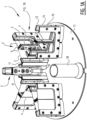
- Figure 1A shows a speaker 1 according to a first embodiment of the invention having five speaker-elements 2 according to a first embodiment of the invention. Two of the speaker-elements 2 are shown transparently.
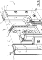
- Figure 1B shows one of the speaker-elements 2 in more detail.
- each speaker-element 2 comprises two substantially mutually opposing spaced apart membrane planes 3.
- each membrane plane 3 is formed by a separate membrane 3, for example made of Mylar.
- Each membrane plane 3 comprises in this embodiment four electromagnetic copper wires 4 arranged for creating a magnetic field upon an electric current passing through said electromagnetic wires 4.
- the wires 4 extend parallel to each other with no or a small distance there between and are attached to the membrane plane using a kapton tape, such that in the figures the wires 4 appear to be one, rather thick wire.
- the wires 4 are arranged in the vertical middle line of the membrane plane 3.
- a permanent magnet 5 is arranged, which is held by two holding plates 6, which are arranged on opposite front and back sides of the magnet 5 for holding the magnet 5 there between. Screws 10 are provided for connecting the plates 6 to each other.
- the magnet 5 extends substantially parallel to the wires 4 and the wires 4 are arranged such that they are in front of the longitudinal side surfaces of the magnet 5.
- a current passes through the wires 4 a magnetic field is created thereby.
- the current passes through the wires 4 in opposite directions 7, 8 in view of the two membrane planes 3 of the speaker-element 2.
- the magnetic fields created by the wires 4 of the two membrane planes 3 are opposite to each other, such that both membrane planes 3 are either attracted towards or repulsed from the magnet 5 and are thus moved in opposite directions.
- the upward direction 7 and downward direction 8 are shown by way of example only and may be reversed, as long as they are opposite to each other. More in particular, the current passing through wires 4 varies continuously between the upward and downward directions, such that the membrane planes 3 are continuously attracted towards and repulsed from the magnet 5, thereby creating sound waves. External sound waves created on the outside of membrane planes 3 can travel outwards, as indicated by arrow 9.
- Insulator elements 11 are provided between neighboring speaker-elements 2 for preventing sound waves that are created internally of the speaker-elements 2 to leave the speaker between neighboring speaker-elements 2.
- the insulator elements may for example be made of rubber or any other suitable material.
- the applicant has found that otherwise the internal sound waves interfere with the external sound waves.
- the applicant has found that the internal sound waves may leave the speaker 1 at a back of the speaker 1, but the effect thereof may be negligible.
- the membrane planes 3 are diverging under an angle ⁇ of 67.5°. As a result of this angle the sound waves travel in a desired direction 9.
- the membrane planes 3 are held by a frame.
- Said frame comprises inner and outer circumferential frame parts 12 - 14, wherein the inner circumferential frame part 12, 13 comprises a central frame part 12 arranged at the converging, small end of the speaker element 2 to which both membrane planes 3 are attached, and which inner frame part splits into two frame parts 13 in the diverging direction of the speaker-element 2.
- Two outer circumferential frame parts 14 are attached to the inner circumferential frame part 12, 13, wherein the membrane planes 3 are arranged between the inner and outer circumferential frame parts 12 - 14 and therefore held tight thereby.
- Rubber angular profiles 15 extend between the membrane planes 3 and the outer circumferential frame parts 14, such that the membrane planes 3 are tensioned.
- the outer and inner frame parts 12 - 14 are attached to each other using screws 16.
- the inner circumferential frame parts 12, 13 close a circumferential edge zone of the speaker-element 2 at the upper, lower, and outer sides thereof, and only the inner side of the circumferential edge zone of the speaker-element is left open, such that sound waves can travel to the inner part of the speaker and then leave the speaker via elements 11 as described above.
- Figure 1A further shows that the speaker-elements 2 are arranged on a substantially circular plate 17.
- the speaker-elements 2 extend radially with respect to the central longitudinal line of the speaker 2 and are spaced apart radially by an angular distance ⁇ of approximately 60°, such that the five speaker-elements 2 together extend over an angular range of the plate 17 of about 300°.
- a cable pipe 18 is provided in the area where no speaker-element 2 is provided.
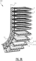
- Figure 2 shows a speaker 1 having two rows of speaker-elements 2.
- the speaker-elements 2 of the two rows are aligned with respect to each other.
- the speaker-elements 2 may be similar to the speaker-elements 2 of figures 1A and 1B and the reader is referred to the above description of figures 1A and 1B for a description thereof.
- the speaker 1 is shown in a front perspective view.
- the cables may be arranged at the back of the speaker 1 where no speaker-element 2 is provided.
- Other hardware of the speaker may for example be arranged under the two rows of speaker elements 2.
- the speaker 1 thus provided has a substantially cylindrical shape.
- Figure 3A shows a speaker 102 with a plurality of speaker-elements 2, which are spaced along and aligned with each other along an imaginary line L.
- a membrane plane 3 substantially faces a membrane plane 3 of an adjacent speaker-element 2, as shown by membrane planes 3-1 and 3-2.
- the imaginary line L is straight.
- Figure 3B shows another embodiment of the speaker 201, which is similar to the speaker 102 of figure 3A , except for the line L which has a straight section L s and a curved section L c .
- the curve of the curved section L c curves away from the non-zero angle between two membrane planes 3-3 and 3-4 of a single speaker-element 2.
- the speaker elements 2 of speakers 101, 102 of figures 3A and 3B comprise the above-described features, unless stated otherwise.
Landscapes
- Engineering & Computer Science (AREA)
- Physics & Mathematics (AREA)
- Acoustics & Sound (AREA)
- Signal Processing (AREA)
- Multimedia (AREA)
- Health & Medical Sciences (AREA)
- Otolaryngology (AREA)
- Audible-Bandwidth Dynamoelectric Transducers Other Than Pickups (AREA)
- Obtaining Desirable Characteristics In Audible-Bandwidth Transducers (AREA)
Claims (12)
- Lautsprecher (1), umfassend eine Vielzahl von Lautsprecherelementen (2), jedes Lautsprecherelement (2) umfassend zwei im Wesentlichen einander gegenüberliegende beabstandete Membranebenen (3), wobei jede Membranebene (3) mindestens einen elektromagnetischen Draht (4) umfasst, der zum Erzeugen eines Magnetfelds bei einem durch den elektromagnetischen Draht (4) fließenden elektrischen Strom angeordnet ist, wobei zwischen den zwei Membranebenen (3) mindestens ein Permanentmagnet (5) angeordnet ist, wobei die elektromagnetischen Drähte (4) der zwei Membranebenen (3) auf eine solche Weise mit einer Quelle von elektrischem Strom verbindbar sind, dass der elektrische Strom in im Wesentlichen einander gegenüberliegenden Richtungen (7, 8) dahindurch fließt und dadurch im Wesentlichen einander gegenüberliegende Magnetfelder derart erzeugt, dass bei dem Fließen eines elektrischen Stroms durch den elektromagnetischen Draht (4) jeder Membranebene (3) die Membranebenen (3) beide entweder zu dem Permanentmagneten (5) angezogen oder von ihm abgestoßen werden und dadurch aufeinander zu beziehungsweise voneinander weg bewegt werden, wodurch eine Schallwelle erzeugt wird, wobei:
der Lautsprecher (1) eine zentrale Längslinie definiert, wobei die Vielzahl von Lautsprecherelementen (2) in einer radialen Richtung in Bezug auf die zentrale Längslinie angeordnet und durch eine Winkelentfernung beabstandet sind. - Lautsprecher (1) nach dem vorstehenden Anspruch, wobei fünf der Lautsprecherelemente (2) bereitgestellt sind, die über eine Winkelentfernung von etwa 60° beabstandet sind.
- Lautsprecher (1) nach dem vorstehenden Anspruch, wobei mindestens eine weitere Reihe von fünf der Lautsprecherelemente (2) bereitgestellt ist, die über eine Winkelentfernung von etwa 60° beabstandet sind, und wobei die mindestens eine weitere Reihe über den fünf Lautsprecherelementen (2) auf eine solche Weise angeordnet ist, dass die Lautsprecherelemente (2) ausgerichtet sind.
- Lautsprecher (1) nach einem der vorstehenden Ansprüche, wobei jeder elektromagnetische Draht (4) jedes der Vielzahl von Lautsprecherelementen (2) im Wesentlichen in einer Mittellinie jeder Membranebene (3) derart angeordnet ist, dass im Wesentlichen gleiche Membranteile auf beiden Seiten des elektromagnetischen Drahtes (4) angeordnet sind.
- Lautsprecher (1) nach einem der vorstehenden Ansprüche, wobei sich der Permanentmagnet (5) jedes der Vielzahl von Lautsprecherelementen (2) im Wesentlichen parallel zu den mindestens zwei elektromagnetischen Drähten (4) mit einer Längslänge davon auf eine solche Weise erstreckt, dass die mindestens zwei elektromagnetischen Drähte (4) vor zwei gegenüberliegenden Längsoberflächen des Permanentmagneten (5) angeordnet sind.
- Lautsprecher (1) nach einem der vorstehenden Ansprüche, wobei die zwei im Wesentlichen einander gegenüberliegenden Membranebenen (3) jedes der Vielzahl von Lautsprecherelementen (2) in einem schrägen Winkel in Bezug aufeinander angeordnet sind, wobei der Winkel vorzugsweise zwischen 0° und 75° gewählt wird.
- Lautsprecher (1) nach einem der vorstehenden Ansprüche, wobei die zwei Membranebenen (3) jedes der Vielzahl von Lautsprecherelementen (2) zusammen eine umlaufende Randzone definieren, wobei die umlaufende Randzone in einem ersten Teil davon geschlossen und in einem zweiten Teil davon offen ist.
- Lautsprecher (1) nach einem der vorstehenden Ansprüche, wobei jede Membranebene (3) jedes der Vielzahl von Lautsprecherelementen (2) vier der elektromagnetischen Drähte (4) umfasst, wobei die vier Drähte (4) ohne oder mit geringer gegenseitiger Entfernung parallel zueinander angeordnet sind.
- Lautsprecher (1) nach einem der vorstehenden Ansprüche, wobei jeder elektromagnetische Draht (4) jedes der Vielzahl von Lautsprecherelementen (2) ein Kupferdraht (4) ist.
- Lautsprecher (1) nach einem der vorstehenden Ansprüche, wobei jeder elektromagnetische Draht (4) jedes der Vielzahl von Lautsprecherelementen (2) unter Verwendung eines Polyimidbandes an der Membranebene (3) befestigt ist.
- Lautsprecher (1) nach einem der vorstehenden Ansprüche, wobei jedes der Vielzahl von Lautsprecherelementen (2) einen Rahmen zum Halten eines umlaufenden Rands jeder Membranebene (3) umfasst, wobei der umlaufende Rand jeder Membranebene (3) zwischen zwei Rahmenteilen (12 - 14) des Rahmens angeordnet und dadurch festgehalten ist.
- Lautsprecher (1) nach dem vorstehenden Anspruch, wobei jedes der Vielzahl von Lautsprecherelementen (2) zwei Winkelprofile (15) aus einem flexiblen und/oder komprimierbaren Material, wie etwa Gummi, umfasst, wobei die Winkelprofile zwischen den Rahmenteilen (12 - 14) im Bereich des umlaufenden Randes der Membranebene (3) zum Spannen der Membranebene (3) angeordnet sind.
Applications Claiming Priority (2)
| Application Number | Priority Date | Filing Date | Title |
|---|---|---|---|
| NL2023714A NL2023714B1 (en) | 2019-08-27 | 2019-08-27 | Speaker-element and speaker comprising such a speaker-element |
| PCT/NL2020/050528 WO2021040520A1 (en) | 2019-08-27 | 2020-08-27 | Speaker-element and speaker comprising such a speaker-element |
Publications (3)
| Publication Number | Publication Date |
|---|---|
| EP4022939A1 EP4022939A1 (de) | 2022-07-06 |
| EP4022939C0 EP4022939C0 (de) | 2024-10-02 |
| EP4022939B1 true EP4022939B1 (de) | 2024-10-02 |
Family
ID=68343414
Family Applications (1)
| Application Number | Title | Priority Date | Filing Date |
|---|---|---|---|
| EP20767625.5A Active EP4022939B1 (de) | 2019-08-27 | 2020-08-27 | Lautsprecherelement und lautsprecher mit einem solchen lautsprecherelement |
Country Status (9)
| Country | Link |
|---|---|
| US (1) | US12177642B2 (de) |
| EP (1) | EP4022939B1 (de) |
| JP (1) | JP7577735B2 (de) |
| KR (1) | KR20220054621A (de) |
| CN (1) | CN114631330B (de) |
| AU (1) | AU2020335849B2 (de) |
| CA (1) | CA3148375A1 (de) |
| NL (1) | NL2023714B1 (de) |
| WO (1) | WO2021040520A1 (de) |
Family Cites Families (11)
| Publication number | Priority date | Publication date | Assignee | Title |
|---|---|---|---|---|
| US5627903A (en) * | 1993-10-06 | 1997-05-06 | Chain Reactions, Inc. | Variable geometry electromagnetic transducer |
| ID23968A (id) * | 1997-07-09 | 2000-06-14 | Sonic Window Kabushiki Kaisha | Peralatan pengubah akustik datar |
| US20020126867A1 (en) * | 2001-03-07 | 2002-09-12 | Eliezer Aizik | Flexible ribbon speaker |
| JP2008131373A (ja) * | 2006-11-21 | 2008-06-05 | Mitsubishi Electric Engineering Co Ltd | 電磁変換器及びスピーカ装置 |
| US8311261B2 (en) | 2009-08-14 | 2012-11-13 | Graber Curtis E | Acoustic transducer array |
| NL2004781C2 (nl) * | 2010-05-31 | 2011-12-01 | Alcons Audio Bv | Luidspreker. |
| CN111010635B (zh) * | 2014-08-18 | 2022-08-30 | 苹果公司 | 旋转对称的扬声器阵列 |
| DE102015121519B4 (de) * | 2015-12-10 | 2018-05-24 | D&B Audiotechnik Gmbh | Verbindungsvorrichtung für Lautsprecherboxen, Anordnung von untereinander hängenden Lautsprecherboxen sowie Verfahren zum Aufbau der Anordnung |
| JP2017118376A (ja) * | 2015-12-25 | 2017-06-29 | 京セラ株式会社 | 電子機器 |
| DE102016222098A1 (de) * | 2016-11-10 | 2018-05-17 | Airbus Operations Gmbh | Lautsprecheranordnung für eine Passagierkabine eines Transportmittels |
| DE102017102219B4 (de) * | 2017-02-06 | 2025-12-31 | Sonova Consumer Hearing Gmbh | Planardynamischer Wandler |
-
2019
- 2019-08-27 NL NL2023714A patent/NL2023714B1/en active
-
2020
- 2020-08-27 US US17/638,089 patent/US12177642B2/en active Active
- 2020-08-27 CN CN202080075187.5A patent/CN114631330B/zh active Active
- 2020-08-27 WO PCT/NL2020/050528 patent/WO2021040520A1/en not_active Ceased
- 2020-08-27 CA CA3148375A patent/CA3148375A1/en active Pending
- 2020-08-27 JP JP2022512398A patent/JP7577735B2/ja active Active
- 2020-08-27 KR KR1020227009477A patent/KR20220054621A/ko active Pending
- 2020-08-27 AU AU2020335849A patent/AU2020335849B2/en active Active
- 2020-08-27 EP EP20767625.5A patent/EP4022939B1/de active Active
Also Published As
| Publication number | Publication date |
|---|---|
| JP2022546350A (ja) | 2022-11-04 |
| CA3148375A1 (en) | 2021-03-04 |
| US20220279282A1 (en) | 2022-09-01 |
| WO2021040520A1 (en) | 2021-03-04 |
| AU2020335849B2 (en) | 2025-05-22 |
| KR20220054621A (ko) | 2022-05-03 |
| EP4022939A1 (de) | 2022-07-06 |
| EP4022939C0 (de) | 2024-10-02 |
| NL2023714B1 (en) | 2021-04-13 |
| US12177642B2 (en) | 2024-12-24 |
| AU2020335849A1 (en) | 2022-03-10 |
| CN114631330A (zh) | 2022-06-14 |
| JP7577735B2 (ja) | 2024-11-05 |
| CN114631330B (zh) | 2025-05-02 |
| WO2021040520A8 (en) | 2021-10-14 |
Similar Documents
| Publication | Publication Date | Title |
|---|---|---|
| US4837838A (en) | Electromagnetic transducer of improved efficiency | |
| KR102691540B1 (ko) | 평면형 마그넷 스피커 | |
| US4037061A (en) | Planar pattern voice coil audio transducer | |
| US5003610A (en) | Whole surface driven speaker | |
| EP0116957B1 (de) | Bandlautsprechersystem | |
| US8520887B2 (en) | Full range planar magnetic transducers and arrays thereof | |
| US4276449A (en) | Speaker or microphone having corrugated diaphragm with conductors thereon | |
| US6963654B2 (en) | Diaphragm, flat-type acoustic transducer, and flat-type diaphragm | |
| US4384173A (en) | Electromagnetic planar diaphragm transducer | |
| WO1999016288A1 (en) | Enhanced efficiency planar transducers | |
| US9900696B2 (en) | Wide-range, wide-angle loudspeaker driver | |
| US20030076977A1 (en) | Planar magnetic transducer | |
| US7940952B2 (en) | Electro-acoustic transducer | |
| EP4022939B1 (de) | Lautsprecherelement und lautsprecher mit einem solchen lautsprecherelement | |
| CN115336288A (zh) | 电声换能器和包括所述电声换能器的扬声器、麦克风和电子设备 | |
| US20140112504A1 (en) | Audio driver and method for transforming an electrical signal into air movement | |
| JP2005027020A (ja) | スピーカモジュール、及びsrスピーカシステム | |
| JP5514699B2 (ja) | 薄型両面スピーカ | |
| AU3402895A (en) | Electro-acoustic transducer | |
| RU2717699C1 (ru) | Безмеандровый изодинамический излучатель |
Legal Events
| Date | Code | Title | Description |
|---|---|---|---|
| STAA | Information on the status of an ep patent application or granted ep patent |
Free format text: STATUS: UNKNOWN |
|
| STAA | Information on the status of an ep patent application or granted ep patent |
Free format text: STATUS: THE INTERNATIONAL PUBLICATION HAS BEEN MADE |
|
| PUAI | Public reference made under article 153(3) epc to a published international application that has entered the european phase |
Free format text: ORIGINAL CODE: 0009012 |
|
| STAA | Information on the status of an ep patent application or granted ep patent |
Free format text: STATUS: REQUEST FOR EXAMINATION WAS MADE |
|
| 17P | Request for examination filed |
Effective date: 20220322 |
|
| AK | Designated contracting states |
Kind code of ref document: A1 Designated state(s): AL AT BE BG CH CY CZ DE DK EE ES FI FR GB GR HR HU IE IS IT LI LT LU LV MC MK MT NL NO PL PT RO RS SE SI SK SM TR |
|
| DAV | Request for validation of the european patent (deleted) | ||
| DAX | Request for extension of the european patent (deleted) | ||
| GRAP | Despatch of communication of intention to grant a patent |
Free format text: ORIGINAL CODE: EPIDOSNIGR1 |
|
| STAA | Information on the status of an ep patent application or granted ep patent |
Free format text: STATUS: GRANT OF PATENT IS INTENDED |
|
| INTG | Intention to grant announced |
Effective date: 20240426 |
|
| GRAS | Grant fee paid |
Free format text: ORIGINAL CODE: EPIDOSNIGR3 |
|
| GRAA | (expected) grant |
Free format text: ORIGINAL CODE: 0009210 |
|
| STAA | Information on the status of an ep patent application or granted ep patent |
Free format text: STATUS: THE PATENT HAS BEEN GRANTED |
|
| AK | Designated contracting states |
Kind code of ref document: B1 Designated state(s): AL AT BE BG CH CY CZ DE DK EE ES FI FR GB GR HR HU IE IS IT LI LT LU LV MC MK MT NL NO PL PT RO RS SE SI SK SM TR |
|
| REG | Reference to a national code |
Ref country code: GB Ref legal event code: FG4D |
|
| REG | Reference to a national code |
Ref country code: CH Ref legal event code: EP |
|
| REG | Reference to a national code |
Ref country code: DE Ref legal event code: R096 Ref document number: 602020038745 Country of ref document: DE |
|
| REG | Reference to a national code |
Ref country code: IE Ref legal event code: FG4D |
|
| U01 | Request for unitary effect filed |
Effective date: 20241029 |
|
| U07 | Unitary effect registered |
Designated state(s): AT BE BG DE DK EE FI FR IT LT LU LV MT NL PT RO SE SI Effective date: 20241108 |
|
| PG25 | Lapsed in a contracting state [announced via postgrant information from national office to epo] |
Ref country code: IS Free format text: LAPSE BECAUSE OF FAILURE TO SUBMIT A TRANSLATION OF THE DESCRIPTION OR TO PAY THE FEE WITHIN THE PRESCRIBED TIME-LIMIT Effective date: 20250202 Ref country code: HR Free format text: LAPSE BECAUSE OF FAILURE TO SUBMIT A TRANSLATION OF THE DESCRIPTION OR TO PAY THE FEE WITHIN THE PRESCRIBED TIME-LIMIT Effective date: 20241002 |
|
| PG25 | Lapsed in a contracting state [announced via postgrant information from national office to epo] |
Ref country code: ES Free format text: LAPSE BECAUSE OF FAILURE TO SUBMIT A TRANSLATION OF THE DESCRIPTION OR TO PAY THE FEE WITHIN THE PRESCRIBED TIME-LIMIT Effective date: 20241002 |
|
| PG25 | Lapsed in a contracting state [announced via postgrant information from national office to epo] |
Ref country code: NO Free format text: LAPSE BECAUSE OF FAILURE TO SUBMIT A TRANSLATION OF THE DESCRIPTION OR TO PAY THE FEE WITHIN THE PRESCRIBED TIME-LIMIT Effective date: 20250102 |
|
| PG25 | Lapsed in a contracting state [announced via postgrant information from national office to epo] |
Ref country code: GR Free format text: LAPSE BECAUSE OF FAILURE TO SUBMIT A TRANSLATION OF THE DESCRIPTION OR TO PAY THE FEE WITHIN THE PRESCRIBED TIME-LIMIT Effective date: 20250103 |
|
| PG25 | Lapsed in a contracting state [announced via postgrant information from national office to epo] |
Ref country code: PL Free format text: LAPSE BECAUSE OF FAILURE TO SUBMIT A TRANSLATION OF THE DESCRIPTION OR TO PAY THE FEE WITHIN THE PRESCRIBED TIME-LIMIT Effective date: 20241002 Ref country code: CZ Free format text: LAPSE BECAUSE OF FAILURE TO SUBMIT A TRANSLATION OF THE DESCRIPTION OR TO PAY THE FEE WITHIN THE PRESCRIBED TIME-LIMIT Effective date: 20241002 |
|
| PG25 | Lapsed in a contracting state [announced via postgrant information from national office to epo] |
Ref country code: RS Free format text: LAPSE BECAUSE OF FAILURE TO SUBMIT A TRANSLATION OF THE DESCRIPTION OR TO PAY THE FEE WITHIN THE PRESCRIBED TIME-LIMIT Effective date: 20250102 |
|
| PG25 | Lapsed in a contracting state [announced via postgrant information from national office to epo] |
Ref country code: SM Free format text: LAPSE BECAUSE OF FAILURE TO SUBMIT A TRANSLATION OF THE DESCRIPTION OR TO PAY THE FEE WITHIN THE PRESCRIBED TIME-LIMIT Effective date: 20241002 |
|
| PG25 | Lapsed in a contracting state [announced via postgrant information from national office to epo] |
Ref country code: SK Free format text: LAPSE BECAUSE OF FAILURE TO SUBMIT A TRANSLATION OF THE DESCRIPTION OR TO PAY THE FEE WITHIN THE PRESCRIBED TIME-LIMIT Effective date: 20241002 |
|
| PLBE | No opposition filed within time limit |
Free format text: ORIGINAL CODE: 0009261 |
|
| STAA | Information on the status of an ep patent application or granted ep patent |
Free format text: STATUS: NO OPPOSITION FILED WITHIN TIME LIMIT |
|
| 26N | No opposition filed |
Effective date: 20250703 |
|
| U20 | Renewal fee for the european patent with unitary effect paid |
Year of fee payment: 6 Effective date: 20250827 |
|
| PGFP | Annual fee paid to national office [announced via postgrant information from national office to epo] |
Ref country code: GB Payment date: 20250827 Year of fee payment: 6 |
|
| REG | Reference to a national code |
Ref country code: CH Ref legal event code: H13 Free format text: ST27 STATUS EVENT CODE: U-0-0-H10-H13 (AS PROVIDED BY THE NATIONAL OFFICE) Effective date: 20260324 |
|
| PG25 | Lapsed in a contracting state [announced via postgrant information from national office to epo] |
Ref country code: MC Free format text: LAPSE BECAUSE OF FAILURE TO SUBMIT A TRANSLATION OF THE DESCRIPTION OR TO PAY THE FEE WITHIN THE PRESCRIBED TIME-LIMIT Effective date: 20241002 |
|
| PG25 | Lapsed in a contracting state [announced via postgrant information from national office to epo] |
Ref country code: CH Free format text: LAPSE BECAUSE OF NON-PAYMENT OF DUE FEES Effective date: 20250831 |