EP4022848B1 - Kartierung von multicast-broadcast-dienstgüteflüssen zu logikkanalidentifikatoren - Google Patents
Kartierung von multicast-broadcast-dienstgüteflüssen zu logikkanalidentifikatoren Download PDFInfo
- Publication number
- EP4022848B1 EP4022848B1 EP20765170.4A EP20765170A EP4022848B1 EP 4022848 B1 EP4022848 B1 EP 4022848B1 EP 20765170 A EP20765170 A EP 20765170A EP 4022848 B1 EP4022848 B1 EP 4022848B1
- Authority
- EP
- European Patent Office
- Prior art keywords
- rnti
- qos flow
- qos
- multicast
- mode
- Prior art date
- Legal status (The legal status is an assumption and is not a legal conclusion. Google has not performed a legal analysis and makes no representation as to the accuracy of the status listed.)
- Active
Links
Images


Classifications
-
- H—ELECTRICITY
- H04—ELECTRIC COMMUNICATION TECHNIQUE
- H04L—TRANSMISSION OF DIGITAL INFORMATION, e.g. TELEGRAPHIC COMMUNICATION
- H04L47/00—Traffic control in data switching networks
- H04L47/10—Flow control; Congestion control
- H04L47/15—Flow control; Congestion control in relation to multipoint traffic
-
- H—ELECTRICITY
- H04—ELECTRIC COMMUNICATION TECHNIQUE
- H04L—TRANSMISSION OF DIGITAL INFORMATION, e.g. TELEGRAPHIC COMMUNICATION
- H04L47/00—Traffic control in data switching networks
- H04L47/70—Admission control; Resource allocation
- H04L47/80—Actions related to the user profile or the type of traffic
- H04L47/806—Broadcast or multicast traffic
-
- H—ELECTRICITY
- H04—ELECTRIC COMMUNICATION TECHNIQUE
- H04W—WIRELESS COMMUNICATION NETWORKS
- H04W28/00—Network traffic management; Network resource management
- H04W28/02—Traffic management, e.g. flow control or congestion control
- H04W28/0252—Traffic management, e.g. flow control or congestion control per individual bearer or channel
- H04W28/0263—Traffic management, e.g. flow control or congestion control per individual bearer or channel involving mapping traffic to individual bearers or channels, e.g. traffic flow template [TFT]
-
- H—ELECTRICITY
- H04—ELECTRIC COMMUNICATION TECHNIQUE
- H04W—WIRELESS COMMUNICATION NETWORKS
- H04W28/00—Network traffic management; Network resource management
- H04W28/02—Traffic management, e.g. flow control or congestion control
- H04W28/0268—Traffic management, e.g. flow control or congestion control using specific QoS parameters for wireless networks, e.g. QoS class identifier [QCI] or guaranteed bit rate [GBR]
-
- H—ELECTRICITY
- H04—ELECTRIC COMMUNICATION TECHNIQUE
- H04W—WIRELESS COMMUNICATION NETWORKS
- H04W4/00—Services specially adapted for wireless communication networks; Facilities therefor
- H04W4/06—Selective distribution of broadcast services, e.g. multimedia broadcast multicast service [MBMS]; Services to user groups; One-way selective calling services
-
- H—ELECTRICITY
- H04—ELECTRIC COMMUNICATION TECHNIQUE
- H04L—TRANSMISSION OF DIGITAL INFORMATION, e.g. TELEGRAPHIC COMMUNICATION
- H04L12/00—Data switching networks
- H04L12/02—Details
- H04L12/16—Arrangements for providing special services to substations
- H04L12/18—Arrangements for providing special services to substations for broadcast or conference, e.g. multicast
- H04L12/189—Arrangements for providing special services to substations for broadcast or conference, e.g. multicast in combination with wireless systems
Definitions
- aspects of the present disclosure generally relate to wireless communication and to techniques and apparatuses for mapping multicast broadcast quality of service flows to logical channel identifiers.
- Wireless communication systems are widely deployed to provide various telecommunication services such as telephony, video, data, messaging, and broadcasts.
- Typical wireless communication systems may employ multiple-access technologies capable of supporting communication with multiple users by sharing available system resources (for example, bandwidth, transmit power, among other examples, or a combination thereof).
- multiple-access technologies include code division multiple access (CDMA) systems, time division multiple access (TDMA) systems, frequency-division multiple access (FDMA) systems, orthogonal frequency-division multiple access (OFDMA) systems, single-carrier frequency-division multiple access (SC-FDMA) systems, time division synchronous code division multiple access (TD-SCDMA) systems, and Long Term Evolution (LTE).
- LTE/LTE-Advanced is a set of enhancements to the Universal Mobile Telecommunications System (UMTS) mobile standard promulgated by the Third Generation Partnership Project (3GPP).
- UMTS Universal Mobile Telecommunications System
- New Radio which may also be referred to as 5G, is a set of enhancements to the LTE mobile standard promulgated by the 3GPP.
- NR is designed to better support mobile broadband Internet access by improving spectral efficiency, lowering costs, improving services, making use of new spectrum, and better integrating with other open standards using orthogonal frequency division multiplexing (OFDM) with a cyclic prefix (CP) (CP-OFDM) on the downlink (DL), using CP-OFDM or SC-FDM (for example, also known as discrete Fourier transform spread OFDM (DFT-s-OFDM)) on the uplink (UL), as well as supporting beamforming, multiple-input multiple-output (MIMO) antenna technology, and carrier aggregation.
- OFDM orthogonal frequency division multiplexing
- SC-FDM for example, also known as discrete Fourier transform spread OFDM (DFT-s-OFDM)
- MIMO multiple-input multiple-output
- LTE single cell point-to-multipoint a single logical channel identifier is used for both a single cell multicast broadcast control channel (SC-MCCH) that carries multicast broadcast control information and a single cell multicast broadcast traffic channel (SC-MTCH) that carries multicast broadcast traffic.
- SC-MCCH single cell multicast broadcast control channel
- SC-MTCH single cell multicast broadcast traffic channel
- LTE SC-PTM is a multicast/broadcast-only system, and communications cannot be switched between multicast/broadcast and unicast, such as for retransmissions to a single UE or individual retransmissions to a small set of UEs.
- EP 3 282 725 discloses a base station that provides multicast service by SC-PTM transmission.
- the base station includes a controller configured to perform processing of transmitting SC-PTM configuration information related to a configuration of the SC-PTM transmission via a GCCH (SC-PTM control channel), which is a logical channel different from a MCCH.
- SC-PTM control channel SC-PTM control channel
- the GCCH is mapped on the DL-SCH.
- US 2018/279262 discloses a wireless device receives message(s) comprising configuration parameters for a first radio bearer; and a first information element indicating that packet duplication is configured for the first radio bearer.
- a control element indicates activation of the packet duplication for the first radio bearer corresponding to a first logical channel and a second logical channel may be received.
- a first uplink grant for transmission of one or more first transport blocks (TBs) is received.
- the one or more first TBs comprise data of one or more first buffers associated with the first logical channels.
- the invention consists of a method of wireless communication, performed by a user equipment according to appended claim 1, and the user equipment according to appended claim 15.
- the user equipment includes means for receiving an indication of a mode for mapping MB-QoS flows to logical channel identifiers and G-RNTIs; means for identifying an MB-QoS flow from a MAC TB based at least in part on the indicated mode; and means for decoding data included in the MB-QoS flow.
- aspects generally include a method, apparatus, system, computer program product, non-transitory computer-readable medium, user equipment, base station, wireless communication device, or processing system as substantially described with reference to and as illustrated by the drawings and specification.
- mapping multicast broadcast quality of service (MB-QoS) flows to logical channel identifiers Some aspects more specifically relate to mapping each MB-QoS flow to a different combination of a logical channel identifier (LCID) and a group radio network temporary identifier (G-RNTI).
- LCID logical channel identifier
- G-RNTI group radio network temporary identifier
- each MB-QoS flow, of a set of MB-QoS flows is mapped to a different LCID and is mapped to a different G-RNTI.
- each MB-QoS flow, of a set of MB-QoS flows is mapped to a different LCID and is mapped to a common G-RNTI used for multiple MB-QoS flows.
- each MB-QoS flow, of a set of MB-QoS flows is mapped to a different G-RNTI and is mapped to a common LCID used for multiple MB-QoS flows.
- each MB-QoS flow, of a set of MB-QoS flows is mapped to a fixed LCID used for all MB-QoS flows and is mapped to at least one of a G-RNTI or a multicast broadcast radio bearer (MRB) identifier that identifies a service type of the MB-QoS flow.
- MRB multicast broadcast radio bearer
- each MB-QoS flow, of a set of MB-QoS flows is mapped to a first LCID and a G-RNTI for multicast or broadcast transmissions and is mapped to a second LCID and a cell radio network temporary identifier (C-RNTI) associated with unicast transmissions.
- C-RNTI cell radio network temporary identifier
- the described techniques can be used to enable retransmission of communications of an MB-QoS flow for higher reliability, such as by using acknowledgement (ACK) or negative acknowledgement (NACK) (collectively, ACK/NACK) feedback.
- ACK acknowledgement
- NACK negative acknowledgement
- the described techniques can be used to enable such retransmissions to be transmitted in multicast/broadcast communications or in unicast communications (for example, for New Radio Mixed Mode communications), thereby increasing system flexibility and, in some cases, conserving network resources and user equipment (UE) resources by transmitting a retransmission to an individual UE rather than a group of UEs.
- ACK acknowledgement
- NACK negative acknowledgement
- the described techniques can be used to enable such retransmissions to be transmitted in multicast/broadcast communications or in unicast communications (for example, for New Radio Mixed Mode communications), thereby increasing system flexibility and, in some cases, conserving network resources and user equipment (UE) resources by transmitting a retransmission to an individual UE rather than
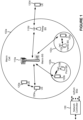
- FIG. 1 is a diagram illustrating an example wireless network in accordance with various aspects of the present disclosure.
- the wireless network may be a Long Term Evolution (LTE) network or some other wireless network, such as a 5G or NR network.
- the wireless network may include a quantity of base stations (BSs) 110 (shown as BS 110a, BS 110b, BS 110c, and BS 110d) and other network entities.
- BSs base stations
- a BS is an entity that communicates with user equipment (UE(s)) and may also be referred to as a Node B, an eNodeB, an eNB, a gNB, a NR BS, a 5G node B (NB), an access point (AP), a transmit receive point (TRP), among other examples, or combinations thereof (these terms are used interchangeably herein).
- UE user equipment
- Each BS may provide communication coverage for a particular geographic area.
- the term "cell" can refer to a coverage area of a BS or a BS subsystem serving this coverage area, depending on the context in which the term is used.
- a BS may provide communication coverage for a macro cell, a pico cell, a femto cell, or another type of cell.
- a macro cell may cover a relatively large geographic area (for example, several kilometers in radius) and may allow unrestricted access by UEs with service subscription.
- a pico cell may cover a relatively small geographic area and may allow unrestricted access by UEs with service subscription.
- a femto cell may cover a relatively small geographic area (for example, a home) and may allow restricted access by UEs having association with the femto cell (for example, UEs in a closed subscriber group (CSG)).
- a BS for a macro cell may be referred to as a macro BS.
- a BS for a pico cell may be referred to as a pico BS.
- a BS for a femto cell may be referred to as a femto BS or a home BS.
- a BS may support one or multiple (for example, three) cells.
- the wireless network may be a heterogeneous network that includes BSs of different types, for example, macro BSs, pico BSs, femto BSs, relay BSs, among other examples, or combinations thereof. These different types of BSs may have different transmit power levels, different coverage areas, and different impacts on interference in the wireless network.
- macro BSs may have a high transmit power level (for example, 5 to 40 Watts) whereas pico BSs, femto BSs, and relay BSs may have lower transmit power levels (for example, 0.1 to 2 Watts).
- a BS 110a may be a macro BS for a macro cell 102a
- a BS 110b may be a pico BS for a pico cell 102b
- a BS 110c may be a femto BS for a femto cell 102c.
- a network controller 130 may couple to the set of BSs 102a, 102b, 110a and 110b, and may provide coordination and control for these BSs.
- Network controller 130 may communicate with the BSs via a backhaul.
- the BSs may also communicate with one another, for example, directly or indirectly via a wireless or wireline backhaul.
- a cell may not be stationary, rather, the geographic area of the cell may move in accordance with the location of a mobile BS.
- the BSs may be interconnected to one another or to one or more other BSs or network nodes (not shown) in the wireless network through various types of backhaul interfaces such as a direct physical connection, a virtual network, among other examples, or combinations thereof using any suitable transport network.
- the wireless network may also include relay stations.
- a relay station is an entity that can receive a transmission of data from an upstream station (for example, a BS or a UE) and send a transmission of the data to a downstream station (for example, a UE or a BS).
- a relay station may also be a UE that can relay transmissions for other UEs.
- a relay station 110d may communicate with macro BS 110a and a UE 120d in order to facilitate communication between BS 110a and UE 120d.
- a relay station may also be referred to as a relay BS, a relay base station, a relay, among other examples, or combinations thereof.
- UEs 120 may be dispersed throughout the wireless network, and each UE may be stationary or mobile.
- a UE may also be referred to as an access terminal, a terminal, a mobile station, a subscriber unit, a station, among other examples, or combinations thereof.
- a UE may be a cellular phone (for example, a smart phone), a personal digital assistant (PDA), a wireless modem, a wireless communication device, a handheld device, a laptop computer, a cordless phone, a wireless local loop (WLL) station, a tablet, a camera, a gaming device, a netbook, a smartbook, an ultrabook, a medical device or equipment, biometric sensors/devices, wearable devices (smart watches, smart clothing, smart glasses, smart wrist bands, smart jewelry (for example, smart ring, smart bracelet)), an entertainment device (for example, a music or video device, or a satellite radio), a vehicular component or sensor, smart meters/sensors, industrial manufacturing equipment, a global positioning system device, or any other suitable device that is configured to communicate via a wireless medium.
- PDA personal digital assistant
- WLL wireless local loop
- MTC and eMTC UEs include, for example, robots, drones, remote devices, sensors, meters, monitors, location tags, among other examples, or combinations thereof, that may communicate with a base station, another device (for example, remote device), or some other entity.
- a wireless node may provide, for example, connectivity for or to a network (for example, a wide area network such as Internet or a cellular network) via a wired or wireless communication link.
- Some UEs may be considered Internet-of Things (IoT) devices, or may be implemented as NB-IoT (narrowband internet of things) devices.
- Some UEs may be considered a Customer Premises Equipment (CPE).
- UE 120 may be included inside a housing that houses components of UE 120, such as processor components, memory components, among other examples, or combinations thereof.
- any quantity of wireless networks may be deployed in a given geographic area.
- Each wireless network may support a particular radio access technology (RAT) and may operate on one or more frequencies or frequency channels.
- RAT radio access technology
- a frequency may also be referred to as a carrier among other examples, or combinations thereof.
- Each frequency may support a single RAT in a given geographic area in order to avoid interference between wireless networks of different RATs.
- NR or 5G RAT networks may be deployed.
- two or more UEs 120 may communicate directly with one another using one or more sidelink channels (for example, without using a base station 110 as an intermediary).
- the UEs 120 may communicate using peer-to-peer (P2P) communications, device-to-device (D2D) communications, a vehicle-to-everything (V2X) protocol (for example, which may include a vehicle-to-vehicle (V2V) protocol, a vehicle-to-infrastructure (V2I) protocol, among other examples, or combinations thereof), a mesh network, among other examples, or combinations thereof.
- V2X vehicle-to-everything
- the UE 120 may perform scheduling operations, resource selection operations, or other operations described elsewhere herein as being performed by the base station 110.
- FIG. 2 is a diagram illustrating an example base station (BS) in communication with a user equipment (UE) in a wireless network in accordance with various aspects of the present disclosure.
- Base station 110 may be equipped with T antennas 234a through 234t
- UE 120 may be equipped with R antennas 252a through 252r, where in general T ⁇ 1 and R ⁇ 1.
- a transmit processor 220 may receive data from a data source 212 for one or more UEs, select one or more modulation and coding schemes (MCSs) for each UE based at least in part on channel quality indicators (CQIs) received from the UE, process (for example, encode) the data for each UE based at least in part on the MCS(s) selected for the UE, and provide data symbols for all UEs. Transmit processor 220 may also process system information (for example, for semi-static resource partitioning information (SRPI) among other examples, or combinations thereof) and control information (for example, CQI requests, grants, upper layer signaling, among other examples, or combinations thereof) and provide overhead symbols and control symbols.
- MCSs modulation and coding schemes
- CQIs channel quality indicators
- Transmit processor 220 may also process system information (for example, for semi-static resource partitioning information (SRPI) among other examples, or combinations thereof) and control information (for example, CQI requests, grants, upper layer signaling, among other examples
- Transmit processor 220 may also generate reference symbols for reference signals (for example, the cell-specific reference signal (CRS)) and synchronization signals (for example, the primary synchronization signal (PSS) and secondary synchronization signal (SSS)).
- a transmit (TX) multiple-input multiple-output (MIMO) processor 230 may perform spatial processing (for example, precoding) on the data symbols, the control symbols, the overhead symbols, or the reference symbols, if applicable, and may provide T output symbol streams to T modulators (MODs) 232a through 232t. Each MOD 232 may process a respective output symbol stream (for example, for OFDM or other examples, or combinations thereof) to obtain an output sample stream.
- TX transmit
- MIMO multiple-input multiple-output
- MIMO multiple-input multiple-output
- Each MOD 232 may process a respective output symbol stream (for example, for OFDM or other examples, or combinations thereof) to obtain an output sample stream.
- Each MOD 232 may further process (for example, convert to analog, amplify, filter, and upconvert) the output sample stream to obtain a downlink signal.
- T downlink signals from MODs 232a through 232t may be transmitted via T antennas 234a through 234t, respectively.
- the synchronization signals can be generated with location encoding to convey additional information.
- antennas 252a through 252r may receive the downlink signals from base station 110 or other base stations and may provide received signals to R demodulators (DEMODs) 254a through 254r, respectively.
- Each DEMOD 254 may condition (for example, filter, amplify, downconvert, and digitize) a received signal to obtain input samples.
- Each DEMOD 254 may further process the input samples (for example, for OFDM or other examples, or combinations thereof) to obtain received symbols.
- a MIMO detector 256 may obtain received symbols from all R DEMODs 254a through 254r, perform MIMO detection on the received symbols if applicable, and provide detected symbols.
- a receive processor 258 may process (for example, decode) the detected symbols, provide decoded data for UE 120 to a data sink 260, and provide decoded control information and system information to a controller/processor 280.
- a channel processor may determine a reference signal received power (RSRP), a received signal strength indicator (RSSI), a reference signal received quality (RSRQ), a channel quality indicator (CQI), among other examples, or combinations thereof.
- RSRP reference signal received power
- RSSI received signal strength indicator
- RSRQ reference signal received quality
- CQI channel quality indicator
- one or more components of UE 120 may be included in a housing.
- a transmit processor 264 may receive and process data from a data source 262 as well as control information (for example, for reports including RSRP, RSSI, RSRQ, CQI, among other examples, or combinations thereof) from controller/processor 280. Transmit processor 264 may also generate reference symbols for one or more reference signals.
- the symbols from transmit processor 264 may be precoded by a TX MIMO processor 266 if applicable, further processed by MODs 254a through 254r (for example, for discrete Fourier transform spread orthogonal frequency division multiplexing (DFT-s-OFDM), orthogonal frequency division multiplexing (OFDM) with a cyclic prefix (CP) (CP-OFDM), among other examples, or combinations thereof), and transmitted to base station 110.
- DFT-s-OFDM discrete Fourier transform spread orthogonal frequency division multiplexing
- OFDM orthogonal frequency division multiplexing with a cyclic prefix
- CP-OFDM cyclic prefix
- the uplink signals from UE 120 and other UEs may be received by antennas 234, processed by DEMODs 232, detected by a MIMO detector 236 if applicable, and further processed by a receive processor 238 to obtain decoded data and control information sent by UE 120.
- Receive processor 238 may provide the decoded data to a data sink 239 and the decoded control information to controller/processor 240.
- Base station 110 may include communication unit 244 and communicate to network controller 130 via communication unit 244.
- Network controller 130 may include communication unit 294, controller/processor 290, and memory 292.
- Controller/processor 240 of base station 110, controller/processor 280 of UE 120, or any other component(s) of Figure 2 may perform one or more techniques associated with mapping multicast broadcast quality of service flows to logical channel identifiers, as described in more detail elsewhere herein.
- controller/processor 240 of base station 110, controller/processor 280 of UE 120, or any other component(s) of Figure 2 may perform or direct operations of, for example, the process of Figure 12 or other processes as described herein.
- Memories 242 and 282 may store data and program codes for base station 110 and UE 120, respectively.
- a scheduler 246 may schedule UEs for data transmission on the downlink or uplink.
- UE 120 may include means for receiving an indication of a mode for mapping MB-QoS flows to logical channel identifiers and G-RNTIs, means for identifying an MB-QoS flow from a medium access control (MAC) TB based at least in part on the indicated mode, means for decoding data included in the MB-QoS flow, among other examples, or combinations thereof.
- MAC medium access control
- such means may include one or more components of UE 120 described in connection with Figure 2 .
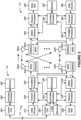
- FIG. 3 is a diagram illustrating an example logical architecture of a distributed radio access network (RAN) in accordance with various aspects of the present disclosure.
- a 5G access node 306 may include an access node controller (ANC) 302.
- the ANC may be a central unit (CU) of the distributed RAN.
- the backhaul interface to the next generation core network (NG-CN) 304 may terminate at the ANC.
- the backhaul interface to neighboring next generation access nodes (NG-ANs) 310 may terminate at the ANC.
- the ANC may include one or more TRPs 308 (which may also be referred to as BSs, NR BSs, Node Bs, 5G NBs, APs, gNB, or some other term). As described above, a TRP may be used interchangeably with "cell.”
- the TRPs 308 may be a distributed unit (DU).
- the TRPs may be connected to one ANC (ANC 302) or more than one ANC (not illustrated).
- ANC 302 ANC
- RaaS radio as a service
- a TRP may include one or more antenna ports.
- the TRPs may be configured to individually (for example, dynamic selection) or jointly (for example, joint transmission) serve traffic to a UE.
- the local architecture of the RAN may be used to support fronthaul definition.
- the architecture may be defined to support fronthauling solutions across different deployment types.
- the architecture may be based at least in part on transmit network capabilities (for example, bandwidth, latency, or jitter).
- NG-AN 310 may support dual connectivity with NR.
- NG-AN 310 may share a common fronthaul for LTE and NR.
- the architecture may enable cooperation between and among TRPs 308. For example, cooperation may be preset within a TRP or across TRPs via the ANC 302. In some aspects, no inter-TRP interface may be needed/present.
- a dynamic configuration of split logical functions may be present within the architecture of the RAN.
- the packet data convergence protocol (PDCP), radio link control (RLC), and MAC protocol layers may be adaptably placed at the ANC or TRP.
- PDCP packet data convergence protocol
- RLC radio link control
- MAC protocol layers may be adaptably placed at the ANC or TRP.
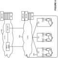
- FIG. 4 is a diagram illustrating an example physical architecture of a distributed RAN in accordance with various aspects of the present disclosure.
- a centralized core network unit (C-CU) 402 may host core network functions.
- the C-CU may be centrally deployed.
- C-CU functionality may be offloaded (for example, to advanced wireless services (AWS)), in an effort to handle peak capacity.
- a centralized RAN unit (C-RU) 404 may host one or more ANC functions.
- the C-RU may host core network functions locally.
- the C-RU may have distributed deployment.
- the C-RU may be closer to the network edge.
- a distributed unit (DU) 406 may host one or more TRPs.
- the DU may be located at edges of the network with radio frequency (RF) functionality.
- RF radio frequency
- FIG. 5 is a diagram illustrating an example channel mapping for multicast broadcast communications in accordance with various aspects of the present disclosure.
- multicast or broadcast transmissions in NR may be supported using a multicast broadcast traffic channel (MBTCH) and a multicast broadcast control channel (MBCCH).
- the MBTCH may carry multicast or broadcast data, while the MBCCH may carry configuration information or control information for multicast or broadcast communications to be transmitted on the MBTCH.
- a multicast or broadcast communication on the MBTCH may be addressed to a group of UEs using a G-RNTI.
- different MBTCHs may be used to carry multicast broadcast traffic with different quality of service (QoS) requirements.
- QoS quality of service
- a multicast/broadcast traffic flow with associated QoS requirements or QoS parameters may be referred to as an MB-QoS flow.
- a base station or a core network device may configure a multicast broadcast radio bearer (MRB) for an MB-QoS flow.
- MRB multicast broadcast radio bearer
- each MBTCH may correspond to an MRB for carrying an MB-QoS flow.
- the MBCCH may carry configuration information for configuring the MBTCHs, and may be addressed to all UEs in a cell (for example, a physical cell or a virtual cell) using a single cell RNTI (SC-RNTI).
- SC-RNTI single cell RNTI
- there is a single MBCCH per cell (physical cell or virtual cell) and the MBCCH carries MBTCH configuration information for multiple multicast/broadcast services with different MB-QoS flows.
- the MBCCH and the MBTCH are logical channels, and may be mapped to a downlink shared channel (DL-SCH) transport channel, which maybe mapped to the PDSCH.
- DL-SCH downlink shared channel
- LTE SC-PTM a single logical channel identifier is used for both a single cell multicast broadcast control channel (SC-MCCH) that carries multicast broadcast control information and a single cell multicast broadcast traffic channel (SC-MTCH) that carries multicast broadcast traffic.
- SC-MCCH single cell multicast broadcast control channel
- SC-MTCH single cell multicast broadcast traffic channel
- LTE SC-PTM uses RLC unacknowledged mode (UM), which does not support any retransmissions, and does not support MAC hybrid automatic repeat request (HARQ) or retransmissions.
- UM RLC unacknowledged mode
- HARQ MAC hybrid automatic repeat request
- LTE SC-PTM is a multicast/broadcast-only system, and communications cannot be switched between multicast/broadcast and unicast, such as for retransmissions to a single UE or individual retransmissions to a small set of UEs.
- MB-QoS flows for example, carried on different MBTCHs
- MBTCHs logical channel identifiers
- One way to uniquely identify MB-QoS flows (or corresponding MBTCHs) is to use different logical channel identifiers (LCIDs) for each MG-QoS flow.
- LCIDs logical channel identifiers
- a large number of MB-QoS flows may need to be supported, such as up to 1024 MB-QoS flows.
- Some techniques and apparatuses described herein permit different MB-QoS flows to be uniquely identified by mapping each MB-QoS flow to a different combination of an LCID and a G-RNTI. This permits retransmission of communications of an MB-QoS flow for higher reliability, such as by using acknowledgement (ACK) or negative acknowledgement (NACK) (collectively, ACK/NACK) feedback.
- ACK acknowledgement
- NACK negative acknowledgement
- some techniques and apparatuses described herein permit such retransmissions to be transmitted in multicast/broadcast communications or in unicast communications (for example, for NR Mixed Mode communications), thereby increasing system flexibility and, in some cases, conserving network resources and UE resources by transmitting a retransmission to an individual UE rather than a group of UEs.
- Figure 6 is a diagram illustrating an example of mapping multicast broadcast quality of service flows to logical channel identifiers in accordance with various aspects of the present disclosure. As shown in Figure 6 , a base station 110 and a UE 120 may communicate with one another.
- the base station 110 may transmit, and the UE 120 may receive, an indication of a mode for mapping MB-QoS flows to logical channel identifiers and G-RNTIs.
- the mode may include a first mode in which each MB-QoS flow, of a first set of MB-QoS flows, is mapped to a different logical channel identifier and is mapped to a different G-RNTI, as described in more detail below in connection with Figure 7 .
- the mode may include a second mode in which each MB-QoS flow, of a second set of MB-QoS flows, is mapped to a different logical channel identifier and is mapped to a common G-RNTI used for multiple MB-QoS flows, as described in more detail below in connection with Figure 8 . Additionally or alternatively, the mode may include a third mode in which each MB-QoS flow, of a third set of MB-QoS flows, is mapped to a different G-RNTI and is mapped to a common logical channel identifier used for multiple MB-QoS flows, as described in more detail below in connection with Figure 9 .
- the mode may include a fourth mode in which each MB-QoS flow, of a fourth set of MB-QoS flows, is mapped to a fixed logical channel identifier used for all MB-QoS flows and is mapped to at least one of a G-RNTI or an MRB identifier that identifies a service type of the MB-QoS flow, as described in more detail below in connection with Figure 10 .
- the mode may include a fifth mode in which each MB-QoS flow, of a fifth set of MB-QoS flows, is mapped to a first logical channel identifier and a G-RNTI for multicast or broadcast transmissions and is mapped to a second logical channel identifier and a cell RNTI (C-RNTI) associated with the UE for unicast transmissions, as described in more detail below in connection with Figure 11 .
- C-RNTI cell RNTI
- the base station 110 may configure and indicate a single mode for all MB-QoS flows. In some aspects, the base station 110 may configure two or more of the modes described herein (for example, two or more of the first mode, the second mode, the third mode, the fourth mode, or the fifth mode). For example, the base station 110 may configure one mode for one set of MB-QoS flows, and may configure another mode for another set of MB-QoS flows.
- the base station 110 may flexibly configure MB-QoS flows depending on, for example, the types of services provided by the MB-QoS flows, a volume of traffic in a cell served by the base station 110, a number of UEs in the cell, a number of UEs subscribed to different MB-QoS flows, a volume of traffic for different MB-QoS flows, among other examples.
- the base station 110 may determine a mode for mapping an MB-QoS flow to an LCID and a G-RNTI based at least in part on whether the MB-QoS flow is a switchable MB-QoS flow or a non-switchable MB-QoS flow.
- a switchable MB-QoS flow may refer to an MB-QoS flow that can be switched between an MRB (for multicast/broadcast transmission) and a dedicated radio bearer (DRB) (for unicast transmission).
- DRB dedicated radio bearer
- a non-switchable MB-QoS flow may refer to an MB-QoS flow that cannot be switched between an MRB (for multicast/broadcast transmission) and a DRB (for unicast transmission).
- the base station 110 may indicate the mode in a radio resource control (RRC) message (for example, an RRC configuration message, an RRC reconfiguration message, among other examples), in downlink control information (DCI), in a medium access control (MAC) control element (CE) (collectively, MAC-CE), in an MBCCH communication, or a combination thereof.
- RRC radio resource control
- DCI downlink control information
- MAC medium access control
- CE control element
- the base station 110 may transmit one or more medium access control (MAC) transport blocks (TBs) that include multiple MB-QoS flows.
- MAC medium access control
- the base station 110 may multiplex multiple MB-QoS flows in a multicast/broadcast transmission using a single MAC TB (for example, using a single transmission of the single MAC TB or multiple transmissions of the single MAC TB).
- the base station 110 may multiplex multiple MB-QoS flows in a multicast/broadcast transmission using multiple (different) MAC TBs.
- a manner in which the multiple MB-QoS flows are multiplexed in a single MAC TB or in multiple MAC TBs may depend on a mode for mapping MB-QoS flows to LCIDs and G-RNTIs, as described in more detail below in connection with Figures 8-12 .
- the base station 110 may transmit an initial transmission of an MB-QoS flow in a multicast/broadcast communication (for example, using an MRB).
- the base station 110 may transmit a retransmission of the initial transmission in a multicast/broadcast communication (for example, using an MRB) or in a unicast communication (for example, using a DRB).
- the UE 120 may identify one or more MB-QoS flows (for example, one or more MB-QoS flows to which the UE 120 is subscribed) from a MAC TB based at least in part on the indicated mode for mapping MB-QoS flows to LCIDs and G-RNTIs.
- a manner in which the UE 120 identifies an MB-QoS flow to which the UE 120 is subscribed may also depend on the mode for mapping MB-QoS flows to LCIDs and G-RNTIs, as described in more detail below in connection with Figures 8-12 .
- the UE 120 may use a different technique for identifying an MB-QoS flow from a multicast/broadcast communication as compared to identifying an MB-QoS flow from a unicast communication, as described in more detail below in connection with Figures 8-12 .
- the UE 120 is subscribed to a first MB-QoS flow (MB-QoS 1) and a third MB-QoS flow (MB-QoS3).
- the UE 120 may decode data included in the identified one or more MB-QoS flows.
- the UE 120 may identify the data for an MB-QoS flow using an LCID identifier included in a MAC TB (for example, in a MAC header or a MAC sub-header) and a G-RNTI.
- the UE 120 may use the G-RNTI to descramble data of the MB-QoS flow in a multicast/broadcast communication. Additionally or alternatively, the UE 120 may use the G-RNTI to identify the MB-QoS flow in a unicast communication.
- the UE 120 may decode the data.
- the UE 120 may decode data of the first MB-QoS flow (MB-QoS1) and the third MB-QoS flow (MB-QoS3).
- MB-QoS flows may be mapped to a limited number of LCIDs, which conserves signaling overhead while also permitting retransmission of MB-QoS for increased reliability.
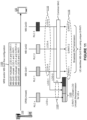
- Figure 7 is a diagram illustrating another example of mapping multicast broadcast quality of service flows to LCIDs in accordance with various aspects of the present disclosure.
- Figure 7 illustrates a first mode in which each MB-QoS flow, of a set of MB-QoS flows, is mapped to a different logical channel identifier and is mapped to a different G-RNTI.
- a base station 110 may indicate one or more modes, for mapping MB-QoS flows to LCIDs and G-RNTIs, to a UE 120.
- different MB-QoS flows may be mapped to different LCIDs.
- the base station 110 may configure a one-to-one mapping between MB-QoS flows and LCIDs, where each MB-QoS flow is mapped to a different LCID.
- different MB-QoS flows may be mapped to different G-RNTIs.
- the base station 110 may configure a one-to-one mapping between MB-QoS flows and G-RNTIs, where each MB-QoS flow is mapped to a different G-RNTI.
- a first MB-QoS flow (MB-QoS1) is mapped to a first LCID (LCID-1) and a first G-RNTI (G-RNTI 1)
- a second MB-QoS flow (MB-QoS2) is mapped to a second LCID (LCID-2) and a second G-RNTI (G-RNTI 2)
- a third MB-QoS flow (MB-QoS3) is mapped to a third LCID (LCID-3) and a third G-RNTI (G-RNTI 3).
- each MB-QoS flow may be associated with a different radio link control (RLC) entity for multicast/broadcast communications (for example, a different MRB).
- RLC radio link control
- the first MB-QoS flow (MB-QoS 1) is associated with a first RLC entity (RLC 1)
- the second MB-QoS flow (MB-QoS2) is associated with a second RLC entity (RLC 2)
- the third MB-QoS flow (MB-QoS3) is associated with a third RLC entity (RLC 3).
- the base station 110 may use a common MAC packet data unit (PDU) to multiplex multiple MB-QoS flows for a multicast broadcast communication (for example, using an MRB).
- the common MAC PDU may include multiple LCIDs that indicate the corresponding multiple MB-QoS flows for which data is included in a multicast/broadcast transmission associated with the common MAC PDU.
- the common MAC PDU may include multiple MAC sub-headers that each include a different LCID.
- the base station 110 may multiplex multiple MB-QoS flows in a multicast or broadcast transmission using a single MAC TB.
- the base station 110 may schedule or transmit the single MAC TB multiple times (for example, by repeating the same contents of the single MAC TB in different time or frequency domain resources), and each MAC TB transmission may be scrambled using a different G-RNTI.
- a first MAC TB transmission that includes the contents of the single MAC TB and that is associated with MB-QoS 1 may be scrambled using G-RNTI 1
- a second MAC TB transmission that includes the contents of the single MAC TB and that is associated with MB-QoS2 may be scrambled using G-RNTI 2
- a third MAC TB transmission that includes the contents of the single MAC TB and that is associated with MB-QoS3 may be scrambled using G-RNTI 3.
- the single MAC TB may be repeated multiple times with different G-RNTIs being used to scramble different repetitions.
- the base station 110 may multiplex multiple MB-QoS flows in a multicast or broadcast transmission using different MAC TBs, where each MAC TB corresponds to a different LCID and is scrambled using a different G-RNTI.
- the UE 120 may identify an MB-QoS flow from a multicast or broadcast transmission using a unique G-RNTI corresponding to that MB-QoS flow. For example, when the UE 120 subscribes to an MB-QoS flow, the UE 120 may receive a G-RNTI for that MB-QoS flow. The UE 120 may then use that G-RNTI to descramble scheduled MBTCH transmissions. If such descrambling is successful, then the UE 120 may obtain data of the MB-QoS flow. As shown, the multicast or broadcast transmission may be an initial transmission or a retransmission.
- the base station 110 may retransmit data of an MB-QoS flow in a unicast transmission.
- the base station 110 may receive a NACK from a UE 120 or may not receive any ACK/NACK feedback from the UE 120 for a data transmission of an MB-QoS flow. This may cause the base station 110 to retransmit the data transmission in a unicast retransmission for the UE 120, in some aspects.
- the base station 110 may include an LCID for each of the MB-QoS flows in the unicast transmission.
- the base station 110 may scramble the unicast transmission using a C-RNTI for the UE 120.
- the unicast transmission may be associated with a different RLC entity (RLC x) than the multicast broadcast transmissions (for example, a DRB) or may have a different LCID, such as an LCID used for unicast transmissions or DRBs.
- RLC x RLC entity
- the base station 110 retransmits data for MB-QoS1 and MB-QoS3 in a unicast transmission.
- the base station 110 includes LCID-1 and LCID-3 in the unicast transmission.
- the base station 110 may transmit the original transmission and the retransmission using the same HARQ process and different redundancy versions to permit the UE 120 to perform HARQ combining (soft combining) of the original transmission and the retransmission
- the UE 120 may identify an MB-QoS flow from a unicast transmission using the C-RNTI for the UE 120 and using an LCID corresponding to that MB-QoS flow.
- the UE 120 may be configured (for example, in an RRC message) with a C-RNTI for unicast communications between the UE 120 and the base station 110.
- the UE 120 may use the C-RNTI to descramble the unicast communication. If such descrambling is successful, then the UE 120 may obtain data of an MB-QoS flow using an LCID associated with that MB-QoS flow.
- the LCID may be indicated in a MAC PDU in the unicast transmission.
- the unicast LCID-x, the multicast broadcast LCID-1, and the multicast broadcast LCID-3 may be multiplexed in the same MAC TB and scrambled using a UE-specific C-RNTI.
- the base station 110 may retransmit the data transmission in a multicast or broadcast transmission to one or more UEs 120, in which case those UEs 120 may obtain the data transmission as described above in connection with operation 720.
- unicast LCID-x is multiplexed with broadcast LCID 1 and LCID 3, as shown in this example, it may not be possible for a receiver (for example, the UE 120) to perform HARQ combining at the receiver due to a change of MAC TB content.
- the base station 110 may retransmit LCID 1 and LCID 3 for a UE 120 in different MAC TBs, each scrambled with the C-RNTI.
- the receiver for example, the UE 120
- the base station 110 may retransmit LCID 1 and LCID 3 for a UE 120 in different MAC TBs, each scrambled with the C-RNTI.
- a UE 120 may be permitted to receive an MB-QoS flow to which that UE 120 is subscribed by using a G-RNTI associated with that MB-QoS flow to descramble a multicast broadcast communication. Furthermore, this mode may enable unicast retransmission of an initial multicast broadcast transmission of an MB-QoS flow using an LCID associated with that MB-QoS flow, thereby improving reliability while conserving resources of UEs 120 that successfully receive the initial multicast broadcast transmission.
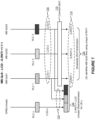
- Figure 8 is a diagram illustrating another example of mapping multicast broadcast quality of service flows to LCIDs in accordance with various aspects of the present disclosure.
- Figure 8 illustrates a second mode in which each MB-QoS flow, of a set of MB-QoS flows, is mapped to a different logical channel identifier and is mapped to a common G-RNTI used for multiple MB-QoS flows.
- a base station 110 may indicate one or more modes, for mapping MB-QoS flows to LCIDs and G-RNTIs, to a UE 120.
- the mode described in connection with Figure 8 may be used for a set of switchable MB-QoS flows that can be switched between an MRB for a multicast or broadcast transmission and a DRB for a unicast transmission.
- different MB-QoS flows may be mapped to different LCIDs.
- the base station 110 may configure a one-to-one mapping between MB-QoS flows and LCIDs, as described above in connection with Figure 7 .
- different MB-QoS flows may be mapped to a common G-RNTI (the same G-RNTI).
- the base station 110 may configure a many-to-one mapping between MB-QoS flows and a G-RNTI, where each MB-QoS flow is mapped to the same G-RNTI.
- a first MB-QoS flow (MB-QoS1) is mapped to a first LCID (LCID-1) and the common G-RNTI
- a second MB-QoS flow (MB-QoS2) is mapped to a second LCID (LCID-2) and the common G-RNTI
- a third MB-QoS flow (MB-QoS3) is mapped to a third LCID (LCID-3) and the common G-RNTI.
- each MB-QoS flow may be associated with a different RLC entity for multicast/broadcast communications, as described above in connection with Figure 7 .
- the base station 110 may use a common MAC PDU to multiplex multiple MB-QoS flows for a multicast broadcast transmissions (for example, using an MRB).
- the common MAC PDU may include multiple LCIDs that indicate the corresponding multiple MB-QoS flows for which data is included in a multicast/broadcast transmission associated with the common MAC PDU.
- the common MAC PDU may include multiple MAC sub-headers that each include a different LCID.
- the base station 110 may multiplex multiple MB-QoS flows in a multicast or broadcast transmission using a single MAC TB.
- the base station 110 may schedule or transmit the single MAC TB using a single transmission (rather than multiple transmissions as described above in connection with Figure 7 ), and the single MAC TB transmission may be scrambled using the common G-RNTI.
- the base station 110 may multiplex multiple MB-QoS flows in a multicast or broadcast transmission using different MAC TBs, where each MAC TB corresponds to a different LCID and is scrambled using the common G-RNTI.
- the UE 120 may identify an MB-QoS flow from a multicast or broadcast transmission (for example, an initial transmission or a retransmission) using the common G-RNTI, used for a set of MB-QoS flows, and an LCID corresponding to the MB-QoS flow. For example, when the UE 120 subscribes to an MB-QoS flow, the UE 120 may receive a common G-RNTI for a set of MB-QoS flows that includes the MB-QoS flow. Additionally or alternatively, the UE 120 may receive or derive a security key for the MB-QoS flow. The UE 120 may use the common G-RNTI to descramble scheduled MBTCH communications.
- the UE 120 may obtain data of the MB-QoS flow using an LCID for the MB-QoS flow. For example, the UE 120 may read the MAC PDU to identify the LCID for the MB-QoS flow (for example, in a MAC sub-header).
- different MB-QoS flows may be associated with different security keys so that a UE 120 cannot obtain data for an MB-QoS flow to which the UE 120 is not subscribed despite having received the common G-RNTI used to descramble a communication that includes the data for the MB-QoS flow.
- the base station 110 may retransmit data of an MB-QoS flow in a unicast transmission, in a similar manner as described above in connection with Figure 7 .
- the base station 110 may include an LCID for each of the MB-QoS flows in the unicast transmission.
- the base station 110 may scramble the unicast transmission using a C-RNTI for the UE 120.
- the unicast transmission may be associated with a different RLC entity (RLC x) than the multicast broadcast transmissions (for example, a DRB) or may have a different LCID, such as an LCID used for unicast transmissions or DRBs.
- RLC x RLC entity
- the base station 110 retransmits data for MB-QoS 1 and MB-QoS3 in a unicast transmission.
- the base station 110 includes LCID-1 and LCID-3 in the unicast transmission.
- the UE 120 may identify an MB-QoS flow from a unicast transmission using the C-RNTI for the UE 120 and using an LCID corresponding to that MB-QoS flow, in a similar manner as described above in connection with Figure 7 .
- the UE 120 may be configured (for example, in an RRC message) with a C-RNTI for unicast communications between the UE 120 and the base station 110.
- the UE 120 may use the C-RNTI to descramble the unicast communication.
- the UE 120 may obtain data of an MB-QoS flow using an LCID associated with that MB-QoS flow, in a similar manner as described above in connection with Figure 7 .
- the LCID may be indicated in a MAC PDU in the unicast transmission.
- unicast LCID-x is multiplexed with broadcast LCID 1 and LCID 3, as shown in this example, it may not be possible for a receiver (for example, the UE 120) to perform HARQ combining at the receiver due to a change of MAC TB content.
- the base station 110 may retransmit LCID 1 and LCID 3 for a UE 120 in different MAC TBs, each scrambled with the C-RNTI.
- the receiver for example, the UE 120
- the base station 110 may retransmit LCID 1 and LCID 3 for a UE 120 in different MAC TBs, each scrambled with the C-RNTI.
- a UE 120 may be permitted to receive an MB-QoS flow to which that UE 120 is subscribed by using a common G-RNTI associated with that MB-QoS flow to descramble a multicast broadcast communication and by using an LCID to identify the MB-QoS flow in the descrambled communication.
- UE resources for example, processing resources, memory resources, battery power, among other examples
- this mode may enable unicast retransmission of an initial multicast broadcast transmission of an MB-QoS flow using an LCID associated with that MB-QoS flow, thereby improving reliability while conserving resources of UEs 120 that successfully receive the initial multicast broadcast transmission.
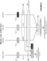
- Figure 9 is a diagram illustrating another example of mapping multicast broadcast quality of service flows to LCIDs in accordance with various aspects of the present disclosure.
- Figure 9 illustrates a third mode in which each MB-QoS flow, of a set of MB-QoS flows, is mapped to a different G-RNTI and is mapped to a common LCID used for multiple MB-QoS flows.
- a base station 110 may indicate one or more modes, for mapping MB-QoS flows to LCIDs and G-RNTIs, to a UE 120.
- the mode described in connection with Figure 9 may be used for a set of switchable MB-QoS flows or a set of non-switchable MB-QoS flows.
- different MB-QoS flows may be mapped to a common LCID (the same LCID).
- the base station 110 may configure a many-to-one mapping between MB-QoS flows and an LCID, where each MB-QoS flow is mapped to the same LCID.
- different MB-QoS flows may be mapped to different G-RNTIs.
- the base station 110 may configure a one-to-one mapping between MB-QoS flows and G-RNTIs, where each MB-QoS flow is mapped to a different G-RNTI.
- a first MB-QoS flow (MB-QoS1) is mapped to the common LCID (LCID-1) and a first G-RNTI (G-RNTI 1)
- a second MB-QoS flow (MB-QoS2) is mapped to the common LCID (LCID-1) and a second G-RNTI (G-RNTI 2)
- a third MB-QoS flow (MB-QoS3) is mapped to the common LCID (LCID-1) and a third G-RNTI (G-RNTI 3).
- each MB-QoS flow may be associated with a different RLC entity for multicast/broadcast communications, as described above in connection with Figure 7 .
- the base station 110 may use a common MAC PDU to multiplex multiple MB-QoS flows for a multicast broadcast transmissions (for example, using an MRB).
- the common MAC PDU may include the common LCID for the multiple MB-QoS flows for which data is included in a multicast/broadcast transmission associated with the common MAC PDU.
- the base station 110 may multiplex multiple MB-QoS flows in a multicast or broadcast transmission using a single MAC TB.
- the base station 110 may schedule or transmit the single MAC TB multiple times (for example, by repeating the same contents of the single MAC TB in different time or frequency domain resources), and each MAC TB transmission may be scrambled using a different G-RNTI.
- a first MAC TB transmission that includes the contents of the single MAC TB and that is associated with MB-QoS 1 may be scrambled using G-RNTI 1
- a second MAC TB transmission that includes the contents of the single MAC TB and that is associated with MB-QoS2 may be scrambled using G-RNTI 2
- a third MAC TB transmission that includes the contents of the single MAC TB and that is associated with MB-QoS3 may be scrambled using G-RNTI 3.
- the single MAC TB may be repeated multiple times with different G-RNTIs being used to scramble different repetitions.
- the base station 110 may multiplex multiple MB-QoS flows in a multicast or broadcast transmission using different MAC TBs, where each MAC TB corresponds to the same LCID and is scrambled using a different G-RNTI.
- the UE 120 may identify an MB-QoS flow from a multicast or broadcast transmission using a unique G-RNTI corresponding to that MB-QoS flow. For example, when the UE 120 subscribes to an MB-QoS flow, the UE 120 may receive a G-RNTI for that MB-QoS flow. The UE 120 may then use that G-RNTI to descramble scheduled MBTCH communications. If such descrambling is successful, then the UE 120 may obtain data of the MB-QoS flow. As shown, the multicast or broadcast transmission may be an initial transmission or a retransmission.
- the base station 110 may retransmit data of an MB-QoS flow in a unicast transmission, in a similar manner as described above in connection with Figure 7 .
- the base station 110 may include a G-RNTI for each of the MB-QoS flows in the unicast transmission.
- the base station 110 may also include the LCID of the MB-QoS flows in the unicast transmission, such that an MB-QoS flow can be identified by a combination of the common LCID and a unique G-RNTI for the MB-QoS flow.
- the base station 110 may scramble the unicast transmission using a C-RNTI for the UE 120.
- the unicast transmission may be associated with a different RLC entity (RLC x) than the multicast broadcast transmissions (for example, a DRB) or may have a different LCID, such as an LCID used for unicast transmissions or DRBs.
- RLC x RLC entity
- the base station 110 retransmits data for MB-QoS1 and MB-QoS3 in a unicast transmission.
- the base station 110 includes G-RNTI 1 and the common LCID, to identify MB-QoS1, as well as G-RNTI 3 and the common LCID, to identify MB-QoS3, in the unicast transmission.
- a G-RNTI may be indicated in a MAC PDU, such as a MAC sub-header, in the unicast transmission.
- the base station 110 may retransmit LCID 1 and LCID 3 for a UE 120 in different MAC TBs, each scrambled with the C-RNTI.
- the receiver for example, the UE 120
- the base station 110 may retransmit LCID 1 and LCID 3 for a UE 120 in different MAC TBs, each scrambled with the C-RNTI.
- the UE 120 may identify an MB-QoS flow from a unicast transmission using the C-RNTI for the UE 120, using the common LCID, and using a G-RNTI corresponding to that MB-QoS flow.
- the UE 120 may be configured (for example, in an RRC message) with a C-RNTI for unicast communications between the UE 120 and the base station 110.
- the UE 120 may use the C-RNTI to descramble the unicast communication. If such descrambling is successful, then the UE 120 may obtain data of an MB-QoS flow using the common LCID and a G-RNTI associated with that MB-QoS flow.
- the common LCID and the G-RNTI may be indicated in a MAC PDU in the broadcast and/or unicast transmission.
- the unicast LCID-x, the multicast broadcast LCID-1, and the multicast broadcast LCID-3 may be multiplexed in the same MAC TB and scrambled using a UE-specific C-RNTI.
- a UE 120 may be permitted to receive an MB-QoS flow to which that UE 120 is subscribed by using a G-RNTI associated with that MB-QoS flow to descramble a multicast broadcast communication. Furthermore, this mode may enable unicast retransmission of an initial multicast broadcast transmission of an MB-QoS flow using a common LCID associated with that MB-QoS flow and the G-RNTI associated with that MB-QoS flow, thereby improving reliability while conserving resources of UEs 120 that successfully receive the initial multicast broadcast transmission. Furthermore, this mode may reduce signaling overhead by using a common LCID for a group of MB-QoS flows, thereby requiring fewer LCIDs than if each MB-QoS flow were associated with a unique LCID.
- Figure 10 is a diagram illustrating another example of mapping multicast broadcast quality of service flows to LCIDs in accordance with various aspects of the present disclosure.
- Figure 10 illustrates a fourth mode in which each MB-QoS flow, of a set of MB-QoS flows, is mapped to a different identifier (for example, a different G-RNTI or a different MRB identifier) and is mapped to a fixed LCID used for all MB-QoS flows.
- a base station 110 may indicate one or more modes, for mapping MB-QoS flows to LCIDs and G-RNTIs, to a UE 120.
- different MB-QoS flows may be mapped to a fixed LCID (the same LCID) that is used for all MB-QoS flows. In this case, each MB-QoS flow is mapped to the same LCID, which is a fixed LCID reserved for multicast/broadcast communications.
- different MB-QoS flows may be mapped to different G-RNTIs, in a similar manner as described elsewhere herein. Additionally or alternatively, different MB-QoS flows may be mapped to different MRB identifiers (MRB IDs).
- MRB IDs MRB identifiers
- a fixed LCID and a unique G-RNTI or MRB ID may be used instead of a common LCID (which may be used for a set of MB-QoS flows that is a subset of all MB-QoS flows).
- a unique G-RNTI may be used to identify an MB-QoS flow in some aspects, in other aspects, a unique MRB ID may be used to identify an MB-QoS flow.
- a common G-RNTI may be used for different MB-QoS flows (for example, all MB-QoS flows).
- the fixed LCID and one of the G-RNTI or the MRB ID may be included in a MAC PDU (for example, in a MAC PDU sub-header), as shown in Figure 10 .
- the fixed LCID may be used to identify the MBTCH, and a unique G-RNTI or a unique MRB ID may be used to identify a multicast/broadcast service type.
- the mode described in connection with Figure 10 may reduce signaling overhead by using the same LCID for all MB-QoS flows, thereby requiring fewer LCIDs than if each MB-QoS flow were associated with a unique LCID or if different sets of MB-QoS flows were associated with different LCIDs.
- Figure 11 is a diagram illustrating another example of mapping multicast broadcast quality of service flows to LCIDs in accordance with various aspects of the present disclosure.
- Figure 11 illustrates a mode in which each MB-QoS flow, of a set of MB-QoS flows, is mapped to a first LCID and a G-RNTI for multicast or broadcast transmissions and is mapped to a second LCID and a C-RNTI for unicast transmissions.
- a base station 110 may indicate one or more modes, for mapping MB-QoS flows to LCIDs and G-RNTIs, to a UE 120.
- Figure 11 shows a proposed enhancement to an NR MAC PDU sub-header (for example, enhancements over section 6.1.2 of 3GPP TS 38.321).
- a first operation 1105 when the base station 110 configures an MRB (for example, for an MB-QoS flow), then the base station 110 may indicate a first LCID (shown as LCID-A for MB-QoS1) to be used when data of the MB-QoS flow is transmitted in a multicast/broadcast communication (for example, using an MRB) and a second LCID (shown as LCID-1 for MB-QoS 1) to be used when data of the MB-QoS flow is transmitted in a unicast communication (for example, using a DRB).
- a first LCID shown as LCID-A for MB-QoS1
- a second LCID shown as LCID-1 for MB-QoS 1
- the base station 110 may also indicate a G-RNTI (shown as G-RNTI 1 for MB-QoS 1) to be used to obtain (descramble) multicast/broadcast communications of the MB-QoS flow using the first LCID , and may indicate a C-RNTI to be used by the UE 120 to obtain (descramble) unicast communications of the MB-QoS flow using the second LCID.
- G-RNTI shown as G-RNTI 1 for MB-QoS 1
- C-RNTI may be used by the UE 120 to obtain (descramble) unicast communications of the MB-QoS flow using the second LCID.
- the base station 110 may indicate (to the UE 120) the first LCID, the G-RNTI, the second LCID, the C-RNTI, or a combination thereof in an RRC message (for example, a unicast RRC message). In some aspects, the base station 110 may indicate all four of these parameters in the RRC message. In some aspects, the base station 110 may indicate (to the UE 120) the second LCID and the C-RNTI in the RRC message, and may indicate the first LCID and the G-RNTI using a multicast control channel (for example, the MBCCH).
- a multicast control channel for example, the MBCCH
- a second operation 1110 when the base station 110 transmits data of the MB-QoS flow in a multicast/broadcast transmission, the base station 110 may use the first LCID.
- the base station 110 may scramble the multicast/broadcast transmission using the G-RNTI.
- the UE 120 may identify the MB-QoS flow or obtain the data of the MB-QoS flow using the G-RNTI, the first LCID, or a combination thereof, in a similar manner as described elsewhere herein.
- a fourth operation 1120 when the base station 110 transmits data of the MB-QoS flow in a unicast transmission, the base station 110 may use the second LCID and may scramble the multicast/broadcast transmission using the C-RNTI.
- the UE 120 may identify the MB-QoS flow or obtain the data of the MB-QoS flow using the C-RNTI and the second LCID, in a similar manner as described elsewhere herein.
- the mode described in connection with Figure 11 may reduce signaling overhead by reusing the same LCID for multiple MB-QoS flows.
- the same LCID may be used for different unicast transmissions that use different UE-specific C-RNTIs.
- MB-QoS flows associated with different G-RNTIs may use the same LCID while still allowing a UE 120 to differentiate between MB-QoS flows using different G-RNTIs.
- a non-switchable MRB may be reconfigured to a switchable MRB.
- a switchable MRB may refer to an MRB that can be switched between multicast/broadcast transmissions (for example, using a G-RNTI) and unicast transmissions (for example, using a C-RNTI).
- a non-switchable MRB may refer to an MRB that cannot be switched between multicast/broadcast transmissions and unicast transmissions.
- a base station 110 may configure a non-switchable MRB with a first LCID for multicast/broadcast transmissions.
- the base station 110 may indicate a second LCID for the MRB for unicast transmissions.
- the base station 110 may reconfigure the MRB with a cell unique LCID or may indicate the second LCID in, for example, a multicast broadcast control channel communication (MBCCH), an RRC message (for example, an RRC reconfiguration message), or a combination thereof.
- MCCH multicast broadcast control channel communication
- RRC message for example, an RRC reconfiguration message
- Figure 12 is a diagram illustrating an example process performed, for example, by a UE, in accordance with various aspects of the present disclosure.
- the example process is an example where the UE (for example, UE 120) performs operations associated with mapping multicast broadcast quality of service flows to LCIDs.
- the process may include receiving an indication of a mode for mapping MB-QoS flows to LCIDs and G-RNTIs (block 1210).
- the UE for example, using receive processor 258, controller/processor 280, memory 282, or reception component 1302 of Figure 13 , among other examples
- the process may include identifying an MB-QoS flow from a MAC TB based at least in part on the indicated mode (block 1220).
- the UE for example, using receive processor 258, controller/processor 280, memory 282, or identification component 1310 of Figure 13 , among other examples
- the process may include decoding data included in the MB-QoS flow (block 1230).
- the UE for example, using receive processor 258, controller/processor 280, memory 282, or decoding component 1312 of Figure 13 , among other examples
- the process may include additional aspects, such as any single aspect or any combination of aspects described below or in connection with one or more other processes described elsewhere herein.
- the mode includes a mode in which each MB-QoS flow, of a set of MB-QoS flows, is mapped to a different logical channel identifier and is mapped to a different G-RNTI.
- the process includes identifying (for example, using identification component 1310 of Figure 13 ) the MB-QoS flow from a multicast or broadcast transmission based at least in part on a unique G-RNTI corresponding to the MB-QoS flow.
- multiple MB-QoS flows are multiplexed in the multicast or broadcast transmission using one of: a single MAC TB that is transmitted multiple times, wherein each MAC TB transmission is scrambled using a different G-RNTI, or different MAC TBs corresponding to different logical channel identifiers, wherein each MAC TB is scrambled using a different G-RNTI.
- the process includes identifying (for example, using identification component 1310 of Figure 13 ) the MB-QoS flow from a unicast transmission based at least in part on a C-RNTI for the UE and a unique logical channel identifier corresponding to the MB-QoS flow.
- the mode includes a mode in which each MB-QoS flow, of a set of MB-QoS flows, is mapped to a different logical channel identifier and is mapped to a common G-RNTI used for multiple MB-QoS flows.
- the process includes identifying (for example, using identification component 1310 of Figure 13 ) the MB-QoS flow from a multicast or broadcast transmission based at least in part on a logical channel identifier corresponding to the MB-QoS flow.
- multiple MB-QoS flows are multiplexed in the multicast or broadcast transmission using one of: a single MAC TB scrambled using the common G-RNTI, or different MAC TBs corresponding to different logical channel identifiers, wherein each MAC TB is scrambled using the common G-RNTI.
- the process includes identifying (for example, using identification component 1310 of Figure 13 ) the MB-QoS flow from a unicast transmission based at least in part on a C-RNTI for the UE and a unique logical channel identifier corresponding to the MB-QoS flow.
- the set of MB-QoS flows includes one or more switchable MB-QoS flows that can be switched between a multicast broadcast radio bearer, for a multicast or broadcast transmission, and a dedicated radio bearer for a unicast transmission.
- the mode includes a mode in which each MB-QoS flow, of a set of MB-QoS flows, is mapped to a different G-RNTI and is mapped to a common logical channel identifier used for multiple MB-QoS flows.
- the process includes identifying (for example, using identification component 1310 of Figure 13 ) the MB-QoS flow from a multicast or broadcast transmission based at least in part on a unique G-RNTI corresponding to the MB-QoS flow.
- multiple MB-QoS flows are multiplexed in the multicast or broadcast transmission using one of: a single MAC TB that is transmitted multiple times, wherein each MAC TB transmission is scrambled using a different G-RNTI, or different MAC TBs corresponding to the common logical channel identifier, wherein each MAC TB is scrambled using a different G-RNTI.
- the process includes identifying (for example, using identification component 1310 of Figure 13 ) the MB-QoS flow from a unicast transmission based at least in part on a C-RNTI for the UE, the common logical channel identifier, and a unique G-RNTI corresponding to the MB-QoS flow.
- the set of MB-QoS flows includes one or more non-switchable MB-QoS flows that cannot be switched between a multicast broadcast radio bearer, for a multicast or broadcast transmission, and a dedicated radio bearer for a unicast transmission.
- the set of MB-QoS flows includes one or more switchable MB-QoS flows that can be switched between a multicast broadcast radio bearer, for a multicast or broadcast transmission, and a dedicated radio bearer for a unicast transmission.
- the mode includes a mode in which each MB-QoS flow, of a set of MB-QoS flows, is mapped to a fixed logical channel identifier used for all MB-QoS flows and is mapped to at least one of a G-RNTI or a multicast broadcast radio bearer identifier that identifies a service type of the MB-QoS flow.
- the process includes identifying (for example, using identification component 1310 of Figure 13 ) the MB-QoS flow based at least in part on a logical channel identifier and at least one of a G-RNTI or a multicast broadcast radio bearer identifier indicated in a MAC PDU sub-header for the MB-QoS flow.
- the mode includes a mode in which each MB-QoS flow, of a set of MB-QoS flows, is mapped to a first logical channel identifier and a G-RNTI for multicast or broadcast transmissions and is mapped to a second logical channel identifier and a C-RNTI associated with the UE for unicast transmissions.
- the first logical channel identifier and the G-RNTI are configured using a multicast control channel
- the second logical channel identifier and the C-RNTI are configured in a radio resource control message.
- the first logical channel identifier, the G-RNTI, the second logical channel identifier, and the C-RNTI are configured in a radio resource control message.
- the MB-QoS flow is associated with a first logical channel identifier and is configured as a non-switchable MB-QoS flow that cannot be switched between a multicast broadcast radio bearer and a dedicated radio bearer; and the process includes receiving an instruction to reconfigure the MB-QoS flow to a switchable MB-QoS flows that can be switched between a multicast broadcast radio bearer and a dedicated radio bearer, wherein the instruction includes a second logical channel identifier for the MB-QoS flow.
- the process includes receiving (for example, using reception component 1302 of Figure 13 ) the instruction in at least one of a multicast control channel communication or a radio resource control message.
- the mode includes at least one of: a first mode in which each MB-QoS flow, of a first set of MB-QoS flows, is mapped to a different logical channel identifier and is mapped to a different G-RNTI, a second mode in which each MB-QoS flow, of a second set of MB-QoS flows, is mapped to a different logical channel identifier and is mapped to a common G-RNTI used for multiple MB-QoS flows, a third mode in which each MB-QoS flow, of a third set of MB-QoS flows, is mapped to a different G-RNTI and is mapped to a common logical channel identifier used for multiple MB-QoS flows, a fourth mode in which each MB-QoS flow, of a fourth set of MB-QoS flows, is mapped to a fixed
- the logical channel identifiers correspond to multicast broadcast traffic channels, and the multicast broadcast traffic channels and a multicast broadcast control channel are carried in a physical downlink shared channel.
- the process includes performing soft combining (for example, using soft combining component 1314 of Figure 13 ) of a first MAC TB of the MB-QoS flow received in a multicast or broadcast transmission scrambled using a G-RNTI and a second MAC TB of the MB-QOS flow received in a unicast transmission scrambled using a cell RNTI.
- soft combining for example, using soft combining component 1314 of Figure 13
- the process includes performing the soft combining (for example, using soft combining component 1314 of Figure 13 ) based at least in part on a determination that the first MAC TB and the second MAC TB carry the same content.
- FIG. 13 is a block diagram of an example apparatus 1300 for wireless communication in accordance with various aspects of the present disclosure.
- the apparatus 1300 may be a UE, or a UE may include the apparatus 1300.
- the apparatus 1300 includes a reception component 1302, a communication manager 1304, and a transmission component 1306, which may be in communication with one another (for example, via one or more buses).
- the apparatus 1300 may communicate with another apparatus 1308 (such as a UE, a base station, or another wireless communication device) using the reception component 1302 and the transmission component 1306.
- another apparatus 1308 such as a UE, a base station, or another wireless communication device
- the apparatus 1300 may be configured to perform one or more operations described herein in connection with Figures 6-11 . Additionally or alternatively, the apparatus 1300 may be configured to perform one or more processes described herein, such as process 1200 of Figure 12 . In some aspects, the apparatus 1300 may include one or more components of the UE described above in connection with Figure 2 .
- the reception component 1302 may receive communications, such as reference signals, control information, data communications, or a combination thereof, from the apparatus 1308.
- the reception component 1302 may provide received communications to one or more other components of the apparatus 1300, such as the communication manager 1304.
- the reception component 1302 may perform signal processing on the received communications (such as filtering, amplification, demodulation, analog-to-digital conversion, demultiplexing, deinterleaving, de-mapping, equalization, interference cancellation, or decoding, among other examples), and may provide the processed signals to the one or more other components.
- the reception component 1302 may include one or more antennas, a demodulator, a MIMO detector, a receive processor, a controller/processor, a memory, or a combination thereof, of the UE described above in connection with Figure 2 .
- the transmission component 1306 may transmit communications, such as reference signals, control information, data communications, or a combination thereof, to the apparatus 1308.
- the communication manager 1304 may generate communications and may transmit the generated communications to the transmission component 1306 for transmission to the apparatus 1308.
- the transmission component 1306 may perform signal processing on the generated communications (such as filtering, amplification, modulation, digital-to-analog conversion, multiplexing, interleaving, mapping, or encoding, among other examples), and may transmit the processed signals to the apparatus 1308.
- the transmission component 1306 may include one or more antennas, a modulator, a transmit MIMO processor, a transmit processor, a controller/processor, a memory, or a combination thereof, of the UE described above in connection with Figure 2 . In some aspects, the transmission component 1306 may be co-located with the reception component 1302 in a transceiver.
- the communication manager 1304 may receive or may cause the reception component 1302 to receive an indication of a mode for mapping MB-QoS flows to logical channel identifiers and G-RNTIs.
- the communication manager 1304 may identify an MB-QoS flow from a MAC TB based at least in part on the indicated mode.
- the communication manager 1304 may decode data included in the MB-QoS flow.
- the communication manager 1304 may include a controller/processor, a memory, or a combination thereof, of the UE described above in connection with Figure 2 .
- the communication manager 1304 may include a set of components, such as an identification component 1310, a decoding component 1312, a soft combining component 1314, or a combination thereof.
- the set of components may be separate and distinct from the communication manager 1304.
- one or more components of the set of components may include or may be implemented within a controller/processor, a memory, or a combination thereof, of the UE described above in connection with Figure 2 .
- one or more components of the set of components may be implemented at least in part as software stored in a memory.
- a component (or a portion of a component) may be implemented as instructions or code stored in a non-transitory computer-readable medium and executable by a controller or a processor to perform the functions or operations of the component.
- the reception component 1310 may receive an indication of a mode for mapping MB-QoS flows to logical channel identifiers and G-RNTIs.
- the identification component 1310 may identify an MB-QoS flow from a MAC TB based at least in part on the indicated mode.
- the decoding component 1312 may decode data included in the MB-QoS flow.
- the identification component 1310 may identify the MB-QoS flow from a unicast transmission based at least in part on a C-RNTI for the UE and a unique logical channel identifier corresponding to the MB-QoS flow. In some aspects, the identification component 1310 may identify the MB-QoS flow from a multicast or broadcast transmission based at least in part on a logical channel identifier corresponding to the MB-QoS flow. In some aspects, the identification component 1310 may identify the MB-QoS flow from a unicast transmission based at least in part on a C-RNTI for the UE and a unique logical channel identifier corresponding to the MB-QoS flow.
- the identification component 1310 may identify the MB-QoS flow from a multicast or broadcast transmission based at least in part on a unique G-RNTI corresponding to the MB-QoS flow. In some aspects, the identification component 1310 may identify the MB-QoS flow from a unicast transmission based at least in part on a C-RNTI for the UE, the common logical channel identifier, and a unique G-RNTI corresponding to the MB-QoS flow.
- the identification component 1310 may identify the MB-QoS flow based at least in part on a logical channel identifier and at least one of a G-RNTI or a multicast broadcast radio bearer identifier indicated in a MAC PDU sub-header for the MB-QoS flow.
- the reception component 1302 may receive the instruction in at least one of a multicast control channel communication or a radio resource control message.
- the soft combining component 1314 may perform soft combining of a first MAC TB of the MB-QoS flow received in a multicast or broadcast transmission scrambled using a G-RNTI and a second MAC TB of the MB-QOS flow received in a unicast transmission scrambled using a cell RNTI.
- the soft combining component 1314 may perform the soft combining based at least in part on a determination that the first MAC TB and the second MAC TB carry the same content.
- FIG. 13 The number and arrangement of components shown in Figure 13 are provided as an example. In practice, there may be additional components, fewer components, different components, or differently arranged components than those shown in Figure 13 . Furthermore, two or more components shown in Figure 13 may be implemented within a single component, or a single component shown in Figure 13 may be implemented as multiple, distributed components. Additionally or alternatively, a set of (one or more) components shown in Figure 13 may perform one or more functions described as being performed by another set of components shown in Figure 13 .
- ком ⁇ онент is intended to be broadly construed as hardware, firmware, or a combination of hardware and software.
- a processor is implemented in hardware, firmware, or a combination of hardware and software.
- satisfying a threshold may refer to a value being greater than the threshold, greater than or equal to the threshold, less than the threshold, less than or equal to the threshold, equal to the threshold, not equal to the threshold, among other examples, or combinations thereof.
- "at least one of: a, b, or c" is intended to cover a, b, c, a-b, a-c, b-c, and a-b-c, as well as any combination with multiples of the same element (for example, a-a, a-a-a, a-a-b, a-a-c, a-b-b, a-c-c, b-b, b-b-b, b-b-c, c-c, and c-c-c or any other ordering of a, b, and c).
Landscapes
- Engineering & Computer Science (AREA)
- Computer Networks & Wireless Communication (AREA)
- Signal Processing (AREA)
- Multimedia (AREA)
- Mobile Radio Communication Systems (AREA)
Claims (15)
- Ein Verfahren für Drahtloskommunikation, das durch eine Nutzereinrichtung bzw. UE (UE = user equipment) durchgeführt wird, das Folgendes aufweist:Empfangen (1210) einer Anzeige eines Modus, der MB-QoS-Flüsse (MB-QoS = multicast broadcast quality of service bzw. Multicast-Broadcast-Dienstqualität) auf Logikkanalidentifikatoren und G-RNTIs (G-RNTI = group radio network temporary identifier bzw. temporärer Gruppenfunknetzwerkidentifikator) abbildet,wobei der angezeigte Modus eines von Folgendem ist:ein erster Modus, in dem jeder MB-QoS-Fluss eines ersten Satzes von MB-QoS-Flüssen auf einen unterschiedlichen Logikkanalidentifikator abgebildet wird und auf einen unterschiedlichen G-RNTI abgebildet wird,ein zweiter Modus, in dem jeder MB-QoS-Fluss eines zweiten Satzes von MB-QoS-Flüssen auf einen unterschiedlichen Logikkanalidentifikator abgebildet wird und auf einen gemeinsamen G-RNTI abgebildet wird, der für mehrere MB-QoS-Flüsse genutzt wird, oderein dritter Modus, in dem jeder MB-QoS-Fluss eines dritten Satzes von MB-QoS-Flüssen auf einen unterschiedlichen G-RNTI abgebildet wird und auf einen gemeinsamen Logikkanalidentifikator abgebildet wird, der für mehrere MB-QoS-Flüsse genutzt wird;Identifizieren (1220) eines MB-QoS-Flusses aus einem Medienzugriffssteuerungs-Transportblock bzw. MAC-TB (MAB = medium access control, TB = transport block) basierend wenigstens teilweise auf dem angezeigten Modus; undDecodieren (1230) von Daten, die in dem MB-QoS-Fluss enthalten sind.
- Verfahren nach Anspruch 1, wobei der angezeigte Modus ein erster Modus ist und das Verfahren weiter Identifizieren des MB-QoS-Flusses aus einer Multicast- oder Broadcast-Sendung aufweist, und zwar basierend wenigstens teilweise auf dem eindeutigen G-RNTI, der dem MB-QoS-Fluss entspricht.
- Verfahren nach Anspruch 2, wobei mehrere MB-QoS-Flüsse in der Multicast- oder Broadcast-Sendung gemultiplext werden, die eines von Folgendem nutzt:einen einzelnen MAC-TB, der mehrere Male gesendet wird, wobei jede MAC-TB-Sendung unter Nutzung eines unterschiedlichen G-RNTI gescrambelt bzw. verwürfelt wird, oderunterschiedliche MAC-TBs, die unterschiedlichen Logikkanalidentifikatoren entsprechen, wobei jeder MAC-TB unter Nutzung eines unterschiedlichen G-RNTI gescrambelt wird.
- Verfahren nach Anspruch 1, wobei der angezeigte Modus der erste Modus ist und das Verfahren weiter Identifizieren des MB-QoS-Flusses aus einer Unicast-Sendung aufweist, und zwar basierend wenigstens teilweise auf einem Zell-RNTI bzw. C-RNTI (C-RNTI = cell RNTI) für die UE und einem eindeutigen Logikkanalidentifikator, der dem MB-QoS-Fluss entspricht.
- Verfahren nach Anspruch 1, wobei der angezeigte Modus der zweite Modus ist und das Verfahren weiter Identifizieren des MB-QoS-Flusses aus einer Multicast- oder Broadcast-Sendung aufweist, und zwar basierend wenigstens teilweise auf einem Logikkanalidentifikator, der dem MB-QoS-Fluss entspricht.
- Verfahren nach Anspruch 5, wobei mehrere MB-QoS-Flüsse in der Multicast- oder Broadcast-Sendung gemultiplext werden unter Nutzung von einem von:einem einzelnen MAC-TB, der unter Nutzung des gemeinsamen G-RNTI gescrambelt bzw. verwürfelt wird, oderunterschiedlichen MAC-TBs, die unterschiedlichen Logikkanalidentifikatoren entsprechen, wobei jeder MAC-TB unter Nutzung des gemeinsamen G-RNTI gescrambelt wird.
- Verfahren nach Anspruch 1, wobei der angezeigte Modus der zweite Modus ist und das Verfahren weiter Identifizieren des MB-QoS-Flusses aus einer Unicast-Sendung aufweist, und zwar basierend wenigstens teilweise auf einem Zell-RNTI bzw. C-RNTI, und einem Logikkanalidentifikator, der dem MB-QoS-Fluss entspricht; oder wobei der angezeigte Modus der zweite Modus ist und der zweite Satz von MB-QoS-Flüssen einen oder mehrere schaltbare bzw. wechselbare MB-QoS-Flüsse aufweist, die umgeschaltet werden können zwischen einem Multicast-Broadcast-Funkträger für eine Multicast- oder Broadcast-Sendung, und einem dedizierten bzw. speziell vorgesehenen Funkträger für eine Unicast-Sendung.
- Verfahren nach Anspruch 1, wobei der angezeigte Modus der dritte Modus ist und das Verfahren weiter Identifizieren des MB-QoS-Flusses aus einer Multicast- oder Broadcast-Sendung basierend wenigstens teilweise auf einem eindeutigen G-RNTI entsprechend dem MB-QoS-Fluss aufweist; oder wobei der angezeigte Modus der dritte Modus ist und das Verfahren weiter Identifizieren des MB-QoS-Flusses aus einer Unicast-Sendung basierend wenigstens teilweise auf einem Zell-RNTI bzw. C-RNTI, dem gemeinsamen Logikkanalidentifikator und einem eindeutigen G-RNTI entsprechend dem MB-QoS-Fluss aufweist; oder wobei der angezeigte Modus der dritte Modus ist und der dritte Satz von MB-QoS-Flüssen einen oder mehrere nicht schaltbare bzw. nicht wechselbare MB-QoS-Flüsse aufweist, die nicht umgeschaltet werden können zwischen einem Multicast-Broadcast-Funkträger für eine Multicast- oder Broadcast-Sendung, und einem dedizierten bzw. speziell vorgesehenen Funkträger für eine Unicast-Sendung; oder
wobei der angezeigte Modus der dritte Modus ist und der dritte Satz von MB-QoS-Flüssen einen oder mehrere schaltbare MB-QoS-Flüsse beinhaltet, die umgeschaltet werden können zwischen einem Multicast-Broadcast-Funkträger für eine Multicast- oder Broadcast-Sendung und einem dedizierten Funkträger für eine Unicast-Sendung. - Verfahren nach Anspruch 1, das weiter Empfangen einer Anzeige eines vierten Modus aufweist, in dem jeder MB-QoS-Fluss eines vierten Satzes von MB-QoS-Flüssen auf einen fixen bzw. festgelegten Logikkanalidentifikator abgebildet wird, der für alle MB-QoS-Flüsse genutzt wird und auf einen Multicast-Broadcast-Funkträgeridentifikator abgebildet wird, der einen Diensttyp eines jeweiligen MB-QoS-Flusses des vierten Satzes identifiziert; oder das weiter Empfangen einer Anzeige eines vierten Modus aufweist, in dem jeder MB-QoS-Fluss eines vierten Satzes von MB-QoS-Flüssen auf einen ersten Logikkanalidentifikator und einen G-RNTI für Multicast- oder Broadcast-Sendungen abgebildet wird und auf einen zweiten Logikkanalidentifikator und einen Zell-RNTI bzw. C-RNTI abgebildet wird, der mit der UE für Unicast-Sendungen assoziiert ist, wobei der erste Logikkanalidentifikator und der G-RNTI für Multicast- oder Broadcast-Sendungen konfiguriert sind unter Nutzung eines Multicast-Steuerkanals, und der zweite Logikkanalidentifikator und der C-RNTI in einer Funkressourcensteuerungsnachricht konfiguriert werden; oder das weiter Empfangen einer Anzeige eines vierten Modus aufweist, in dem jeder MB-QoS-Fluss eines vierten Satzes von MB-QoS-Flüssen auf einen ersten Logikkanalidentifikator und einen G-RNTI für Multicast- oder Broadcast-Sendungen abgebildet wird und auf einen zweiten Logikkanalidentifikator und einen Zell-RNTI bzw. C-RNTI abgebildet wird, der mit der UE für Unicast-Sendungen assoziiert ist, wobei der erste Logikkanalidentifikator, der G-RNTI für Multicast- oder Broadcast-Sendungen, der zweite Logikkanalidentifikator und der C-RNTI in einer Funkressourcensteuerungsnachricht konfiguriert werden; oder wobei die Logikkanalidentifikatoren Multicast-Broadcast-Verkehrskanälen entsprechen, und wobei die Multicast-Broadcast-Verkehrskanäle und ein Multicast-Broadcast-Steuerkanal in einem physischen gemeinsam genutzten Abwärtsstreckenkanal getragen werden.
- Verfahren nach Anspruch 1, das weiter Identifizieren des MB-QoS-Flusses basierend wenigstens teilweise auf einem Logikkanalidentifikator und wenigstens einem von einem G-RNTI oder eine Multicast-Broadcast-Funkträgeridentifikator aufweist, der in einem MAC-PDU-Subheader (PDU = packet data unit bzw. Paketdateneinheit) für den MB-QoS-Fluss angezeigt wird.
- Verfahren nach Anspruch 1, wobei der MB-QoS-Fluss mit einem ersten Logikkanalidentifikator assoziiert ist und als ein nicht schaltbarer bzw. wechselbarer MB-QoS-Fluss konfiguriert ist, der nicht zwischen einem Multicast-Broadcast-Funkträger und einem dedizierten Funkträger umgeschaltet werden kann; und
wobei das Verfahren weiter Empfangen eines Befehls zum Rekonfigurieren des MB-QoS-Flusses auf einen schaltbaren MB-QoS-Fluss aufweist, der umgeschaltet werden kann zwischen dem Multicast-Broadcast-Funkträger und dem dedizierten Funkträger, wobei der Befehl einen zweiten Logikkanalidentifikator für den MB-QoS-Fluss aufweist. - Verfahren nach Anspruch 11, das weiter Empfangen des Befehls in wenigstens einem von einer Multicast-Steuerkanalkommunikation oder einer Funkressourcensteuerungsnachricht aufweist.
- Verfahren nach Anspruch 1, das weiter Durchführen von Soft-Kombinieren eines ersten MAC-TB des MB-QoS-Flusses, der in einer Multicast- oder Broadcast-Sendung empfangen wird, die unter Nutzung eines G-RNTI verwürfelt wird, und eines zweiten MAC-TB des MB-QoS-Flusses, der in einer Unicast-Sendung empfangen wird, die unter Nutzung eines Zell-RNTI verwürfelt wird, aufweist.
- Verfahren nach Anspruch 13, das weiter Durchführen des Soft-Kombinierens basierend wenigstens teilweise auf einer Bestimmung aufweist, dass der erste MAC-TB und der zweite MAC-TB den gleichen Inhalt tragen.
- Eine Nutzereinrichtung bzw. UE (UE = user equipment) (120) für Drahtloskommunikation, die Folgendes aufweist:einen Speicher; undeinen oder mehrere Prozessoren, die an den Speicher gekoppelt sind, wobei der Speicher und der eine oder die mehreren Prozessoren konfiguriert sind zum:Empfangen (1210) einer Anzeige eines Modus, der MB-QoS-Flüsse (MB-QoS = multicast broadcast quality of service bzw. Multicast-Broadcast-Dienstqualität) auf Logikkanalidentifikatoren und G-RNTIs (G-RNTI = group radio network temporary identifier bzw. temporärer Gruppenfunknetzwerkidentifikator) abbildet,wobei der angezeigte Modus eines von Folgendem ist:ein erster Modus, in dem jeder MB-QoS-Fluss eines ersten Satzes von MB-QoS-Flüssen auf einen unterschiedlichen Logikkanalidentifikator abgebildet wird und auf einen unterschiedlichen G-RNTI abgebildet wird,ein zweiter Modus, in dem jeder MB-QoS-Fluss eines zweiten Satzes von MB-QoS-Flüssen auf einen unterschiedlichen Logikkanalidentifikator abgebildet wird und auf einen gemeinsamen G-RNTI abgebildet wird, der für mehrere MB-QoS-Flüsse genutzt wird, oderein dritter Modus, in dem jeder MB-QoS-Fluss eines dritten Satzes von MB-QoS-Flüssen auf einen unterschiedlichen G-RNTI abgebildet wird und auf einen gemeinsamen Logikkanalidentifikator abgebildet wird, der für mehrere MB-QoS-Flüsse genutzt wird;Identifizieren (1220) eines MB-QoS-Flusses aus einem Medienzugriffssteuerungs-Transportblock bzw. MAC-TB (MAB = medium access control, TB = transport block) basierend wenigstens teilweise auf dem angezeigten Modus; undDecodieren (1230) von Daten, die in dem MB-QoS-Fluss enthalten sind.
Applications Claiming Priority (3)
| Application Number | Priority Date | Filing Date | Title |
|---|---|---|---|
| US201962894582P | 2019-08-30 | 2019-08-30 | |
| US16/998,608 US11533653B2 (en) | 2019-08-30 | 2020-08-20 | Mapping multicast broadcast quality of service flows to logical channel identifiers |
| PCT/US2020/047353 WO2021041193A1 (en) | 2019-08-30 | 2020-08-21 | Mapping multicast broadcast quality of service flows to logical channel identifiers |
Publications (3)
| Publication Number | Publication Date |
|---|---|
| EP4022848A1 EP4022848A1 (de) | 2022-07-06 |
| EP4022848B1 true EP4022848B1 (de) | 2024-08-07 |
| EP4022848C0 EP4022848C0 (de) | 2024-08-07 |
Family
ID=74681972
Family Applications (1)
| Application Number | Title | Priority Date | Filing Date |
|---|---|---|---|
| EP20765170.4A Active EP4022848B1 (de) | 2019-08-30 | 2020-08-21 | Kartierung von multicast-broadcast-dienstgüteflüssen zu logikkanalidentifikatoren |
Country Status (4)
| Country | Link |
|---|---|
| US (1) | US11533653B2 (de) |
| EP (1) | EP4022848B1 (de) |
| CN (2) | CN114270883B (de) |
| WO (1) | WO2021041193A1 (de) |
Families Citing this family (26)
| Publication number | Priority date | Publication date | Assignee | Title |
|---|---|---|---|---|
| US20190150176A1 (en) * | 2016-05-12 | 2019-05-16 | Idac Holdings, Inc. | Flow-based processing in wireless systems |
| CN121013188A (zh) * | 2019-07-31 | 2025-11-25 | 华为技术有限公司 | 一种通信方法及装置 |
| US11533653B2 (en) * | 2019-08-30 | 2022-12-20 | Qualcomm Incorporated | Mapping multicast broadcast quality of service flows to logical channel identifiers |
| WO2021158024A1 (en) * | 2020-02-05 | 2021-08-12 | Lg Electronics Inc. | Method and apparatus for switching of multicast and broadcast service between multicast and unicast in a wireless communication system |
| CN113271551B (zh) * | 2020-02-17 | 2022-07-05 | 大唐移动通信设备有限公司 | 一种数据流传输方法、终端和网络侧设备 |
| KR20210119703A (ko) * | 2020-03-25 | 2021-10-06 | 삼성전자주식회사 | 무선통신시스템에서 멀티캐스트 브로드캐스트 서비스에 harq를 적용하기 위한 방법 및 장치 |
| CN111901766B (zh) * | 2020-04-27 | 2026-01-02 | 中兴通讯股份有限公司 | 承载配置、上下文信息管理、释放方法、装置和设备 |
| CN111901765A (zh) * | 2020-04-27 | 2020-11-06 | 中兴通讯股份有限公司 | 模式配置方法、装置、设备和存储介质 |
| US11722855B2 (en) * | 2020-05-05 | 2023-08-08 | Qualcomm Incorporated | Handling of multicast service data transport for mobility between supporting and non-supporting access nodes |
| WO2022021232A1 (zh) * | 2020-07-30 | 2022-02-03 | 华为技术有限公司 | 用于组播通信的方法、第一网络设备和第二网络设备 |
| CN116491177B (zh) * | 2020-08-03 | 2025-01-28 | 诺基亚通信公司 | 用于无线电通信的方法和装置 |
| CN114071367B (zh) * | 2020-08-04 | 2022-09-09 | 大唐移动通信设备有限公司 | 单播多播转换方法、装置及处理器可读存储介质 |
| WO2022030518A1 (ja) * | 2020-08-05 | 2022-02-10 | 京セラ株式会社 | 通信制御方法 |
| EP4211934A1 (de) * | 2020-09-10 | 2023-07-19 | Toyota Jidosha Kabushiki Kaisha | System und verfahren zur aufrechterhaltung der multicast-broadcast-dienstkontinuität in inaktiven und inaktiven zuständen |
| TWI792614B (zh) * | 2020-10-19 | 2023-02-11 | 新加坡商聯發科技(新加坡)私人有限公司 | 用於多播廣播服務的方法和使用者設備 |
| KR102585504B1 (ko) * | 2020-10-22 | 2023-10-06 | 엘지전자 주식회사 | 무선 통신 시스템에서 사용자 단말에 의해 멀티캐스트/브로드캐스트 서비스 신호를 처리하기 위한 방법 및 장치 |
| US12317158B2 (en) * | 2020-11-16 | 2025-05-27 | Ofinno, Llc | Channel state information report for multicast and broadcast services |
| WO2022151294A1 (zh) * | 2021-01-14 | 2022-07-21 | 华为技术有限公司 | 通信方法及装置 |
| CN115038048B (zh) * | 2021-03-05 | 2023-07-07 | 维沃移动通信有限公司 | 多播业务的接收方法、配置方法、终端及网络侧设备 |
| TWI809753B (zh) * | 2021-03-12 | 2023-07-21 | 新加坡商聯發科技(新加坡)私人有限公司 | 多播廣播服務並行傳輸方法和使用者設備 |
| WO2022240184A1 (ko) * | 2021-05-11 | 2022-11-17 | 엘지전자 주식회사 | 무선 통신 시스템에서 그룹 공통 전송을 위한 harq 기반 송수신 방법 및 장치 |
| EP4388729A4 (de) | 2021-08-17 | 2025-05-28 | LG Electronics Inc. | Verfahren und vorrichtung zum empfangen von multicast-daten durch ein benutzergerät in einem drahtloskommunikationssystem |
| JP7727846B2 (ja) * | 2021-10-21 | 2025-08-21 | グーグル エルエルシー | マルチキャストおよびユニキャストワイヤレスデータ送信の管理 |
| CN116684827A (zh) * | 2022-02-23 | 2023-09-01 | 上海朗帛通信技术有限公司 | 一种被用于无线通信中的方法和装置 |
| CN116980971A (zh) * | 2022-04-21 | 2023-10-31 | 索尼集团公司 | 无线通信系统中的电子设备和方法 |
| US12592790B2 (en) * | 2022-09-22 | 2026-03-31 | Qualcomm Incorporated | Modulation based hybrid automatic repeat request feedback retransmission design |
Family Cites Families (19)
| Publication number | Priority date | Publication date | Assignee | Title |
|---|---|---|---|---|
| KR100893070B1 (ko) * | 2002-09-19 | 2009-04-17 | 엘지전자 주식회사 | 무선통신 시스템의 멀티캐스트 서비스 제공 및 수신 방법, 그리고 그 장치 |
| CN101166145B (zh) * | 2006-10-18 | 2011-09-14 | 华为技术有限公司 | 多播广播业务下行发送方法及其系统 |
| CN101932007B (zh) * | 2009-06-22 | 2014-02-26 | 中兴通讯股份有限公司 | 一种实现移动终端业务流传输的方法及无线中继系统 |
| EP2517524A1 (de) * | 2009-12-22 | 2012-10-31 | Fujitsu Limited | Übertragung in einem kommunikationssystem mit relaisknoten |
| GB2488532B (en) * | 2011-02-18 | 2013-06-05 | Sca Ipla Holdings Inc | Communication units and methods for control change notification in broadcast communication |
| CN102547592B (zh) * | 2012-01-06 | 2015-02-18 | 电信科学技术研究院 | 一种数据传输方法及装置 |
| US9591460B2 (en) * | 2012-08-31 | 2017-03-07 | Qualcomm Incorporated | Application layer related group priority access using eMBMS and LTE priority access |
| US9210717B2 (en) * | 2012-11-15 | 2015-12-08 | Qualcomm Incorporated | Methods and apparatus for LTE MAC logical channel prioritization based on control data |
| US9473906B2 (en) * | 2013-03-22 | 2016-10-18 | Mediatek Inc. | Idle mode reception for group communication over LTE eMBMS |
| US20150124686A1 (en) * | 2013-11-06 | 2015-05-07 | Qualcomm Incorporated | Adaptive broadcast multicast service area and adaptive single frequency network area |
| US9749816B2 (en) * | 2014-09-25 | 2017-08-29 | Samsung Electronics Co., Ltd | Method and system for decoding MBSFN data |
| EP3282725B1 (de) | 2015-04-10 | 2019-10-02 | Kyocera Corporation | Basisstation und benutzerendgerät |
| CN107734465B (zh) * | 2016-08-12 | 2019-12-20 | 电信科学技术研究院 | 传输多播业务的方法、接收多播业务的方法及装置 |
| WO2018049347A1 (en) * | 2016-09-12 | 2018-03-15 | Kyocera Corporation | Layered modulation for machine type communication (mtc) transmissions from multiple transceiver stations |
| EP3520537B1 (de) * | 2016-09-29 | 2021-10-27 | LG Electronics Inc. | Uplink-übertragung auf der basis einer ul-berechtigung im zusammenhang mit der priorität eines spezifischen logischen kanals |
| WO2018075828A1 (en) * | 2016-10-19 | 2018-04-26 | Convida Wireless, Llc | Apparatus |
| US10432761B2 (en) * | 2017-01-18 | 2019-10-01 | Qualcomm Incorporated | Techniques for handling internet protocol flows in a layer 2 architecture of a wireless device |
| US10716094B2 (en) | 2017-03-23 | 2020-07-14 | Ofinno, Llc | Packet duplication in a wireless device and wireless network |
| US11533653B2 (en) * | 2019-08-30 | 2022-12-20 | Qualcomm Incorporated | Mapping multicast broadcast quality of service flows to logical channel identifiers |
-
2020
- 2020-08-20 US US16/998,608 patent/US11533653B2/en active Active
- 2020-08-21 WO PCT/US2020/047353 patent/WO2021041193A1/en not_active Ceased
- 2020-08-21 CN CN202080059060.4A patent/CN114270883B/zh active Active
- 2020-08-21 EP EP20765170.4A patent/EP4022848B1/de active Active
- 2020-08-21 CN CN202310827838.7A patent/CN116614784B/zh active Active
Also Published As
| Publication number | Publication date |
|---|---|
| CN114270883B (zh) | 2023-07-04 |
| CN116614784B (zh) | 2025-07-29 |
| CN116614784A (zh) | 2023-08-18 |
| EP4022848A1 (de) | 2022-07-06 |
| US11533653B2 (en) | 2022-12-20 |
| CN114270883A (zh) | 2022-04-01 |
| WO2021041193A1 (en) | 2021-03-04 |
| US20210068004A1 (en) | 2021-03-04 |
| EP4022848C0 (de) | 2024-08-07 |
Similar Documents
| Publication | Publication Date | Title |
|---|---|---|
| EP4022848B1 (de) | Kartierung von multicast-broadcast-dienstgüteflüssen zu logikkanalidentifikatoren | |
| US12120711B2 (en) | Scheduling broadcast or multicast communications for new radio | |
| US11729756B2 (en) | Techniques and apparatuses for prioritization for transmission power control in 5G | |
| US11438854B2 (en) | Synchronization signal block configuration | |
| US11800541B2 (en) | Coordination between multicast/broadcast communication and unicast communication | |
| US11765723B2 (en) | Scheduling via wireless communication relay | |
| EP3711241A1 (de) | Übertragung von uplink-steuerungsinformationen | |
| US11310004B2 (en) | Master node transport network layer information exchange for downlink data forwarding of a secondary node terminated bearer | |
| US11470588B2 (en) | Techniques for managing physical uplink control channel grouping for multiple transmit receive points | |
| US12395228B2 (en) | Techniques for repeating a transport block using spatial division multiplexing | |
| US11606810B2 (en) | Sidelink communication resource signaling | |
| WO2021119647A1 (en) | Management of resources in integrated access and backhaul | |
| CN116264857B (zh) | 与方向范围相关联的分组的复制 | |
| US11259334B2 (en) | Code-block-based communication for random access channel | |
| US20240284335A1 (en) | Wakeup signal (wus) resource configuration for sidelink wireless communications |
Legal Events
| Date | Code | Title | Description |
|---|---|---|---|
| STAA | Information on the status of an ep patent application or granted ep patent |
Free format text: STATUS: UNKNOWN |
|
| STAA | Information on the status of an ep patent application or granted ep patent |
Free format text: STATUS: THE INTERNATIONAL PUBLICATION HAS BEEN MADE |
|
| PUAI | Public reference made under article 153(3) epc to a published international application that has entered the european phase |
Free format text: ORIGINAL CODE: 0009012 |
|
| STAA | Information on the status of an ep patent application or granted ep patent |
Free format text: STATUS: REQUEST FOR EXAMINATION WAS MADE |
|
| 17P | Request for examination filed |
Effective date: 20220201 |
|
| AK | Designated contracting states |
Kind code of ref document: A1 Designated state(s): AL AT BE BG CH CY CZ DE DK EE ES FI FR GB GR HR HU IE IS IT LI LT LU LV MC MK MT NL NO PL PT RO RS SE SI SK SM TR |
|
| DAV | Request for validation of the european patent (deleted) | ||
| DAX | Request for extension of the european patent (deleted) | ||
| REG | Reference to a national code |
Ref country code: DE Ref legal event code: R079 Free format text: PREVIOUS MAIN CLASS: H04L0012180000 Ipc: H04L0047100000 Ref country code: DE Ref legal event code: R079 Ref document number: 602020035379 Country of ref document: DE Free format text: PREVIOUS MAIN CLASS: H04L0012180000 Ipc: H04L0047100000 |
|
| GRAP | Despatch of communication of intention to grant a patent |
Free format text: ORIGINAL CODE: EPIDOSNIGR1 |
|
| STAA | Information on the status of an ep patent application or granted ep patent |
Free format text: STATUS: GRANT OF PATENT IS INTENDED |
|
| RIC1 | Information provided on ipc code assigned before grant |
Ipc: H04W 28/02 20090101ALI20240215BHEP Ipc: H04W 4/06 20090101ALI20240215BHEP Ipc: H04L 12/18 20060101ALI20240215BHEP Ipc: H04L 47/80 20220101ALI20240215BHEP Ipc: H04L 47/10 20220101AFI20240215BHEP |
|
| INTG | Intention to grant announced |
Effective date: 20240301 |
|
| GRAS | Grant fee paid |
Free format text: ORIGINAL CODE: EPIDOSNIGR3 |
|
| GRAA | (expected) grant |
Free format text: ORIGINAL CODE: 0009210 |
|
| STAA | Information on the status of an ep patent application or granted ep patent |
Free format text: STATUS: THE PATENT HAS BEEN GRANTED |
|
| AK | Designated contracting states |
Kind code of ref document: B1 Designated state(s): AL AT BE BG CH CY CZ DE DK EE ES FI FR GB GR HR HU IE IS IT LI LT LU LV MC MK MT NL NO PL PT RO RS SE SI SK SM TR |
|
| REG | Reference to a national code |
Ref country code: GB Ref legal event code: FG4D |
|
| REG | Reference to a national code |
Ref country code: CH Ref legal event code: EP |
|
| REG | Reference to a national code |
Ref country code: IE Ref legal event code: FG4D |
|
| REG | Reference to a national code |
Ref country code: DE Ref legal event code: R096 Ref document number: 602020035379 Country of ref document: DE |
|
| U01 | Request for unitary effect filed |
Effective date: 20240827 |
|
| U07 | Unitary effect registered |
Designated state(s): AT BE BG DE DK EE FI FR IT LT LU LV MT NL PT RO SE SI Effective date: 20240905 |
|
| U20 | Renewal fee for the european patent with unitary effect paid |
Year of fee payment: 5 Effective date: 20241126 |
|
| PG25 | Lapsed in a contracting state [announced via postgrant information from national office to epo] |
Ref country code: NO Free format text: LAPSE BECAUSE OF FAILURE TO SUBMIT A TRANSLATION OF THE DESCRIPTION OR TO PAY THE FEE WITHIN THE PRESCRIBED TIME-LIMIT Effective date: 20241107 |
|
| PG25 | Lapsed in a contracting state [announced via postgrant information from national office to epo] |
Ref country code: GR Free format text: LAPSE BECAUSE OF FAILURE TO SUBMIT A TRANSLATION OF THE DESCRIPTION OR TO PAY THE FEE WITHIN THE PRESCRIBED TIME-LIMIT Effective date: 20241108 Ref country code: PL Free format text: LAPSE BECAUSE OF FAILURE TO SUBMIT A TRANSLATION OF THE DESCRIPTION OR TO PAY THE FEE WITHIN THE PRESCRIBED TIME-LIMIT Effective date: 20240807 |
|
| PG25 | Lapsed in a contracting state [announced via postgrant information from national office to epo] |
Ref country code: IS Free format text: LAPSE BECAUSE OF FAILURE TO SUBMIT A TRANSLATION OF THE DESCRIPTION OR TO PAY THE FEE WITHIN THE PRESCRIBED TIME-LIMIT Effective date: 20241207 |
|
| PG25 | Lapsed in a contracting state [announced via postgrant information from national office to epo] |
Ref country code: HR Free format text: LAPSE BECAUSE OF FAILURE TO SUBMIT A TRANSLATION OF THE DESCRIPTION OR TO PAY THE FEE WITHIN THE PRESCRIBED TIME-LIMIT Effective date: 20240807 |
|
| PG25 | Lapsed in a contracting state [announced via postgrant information from national office to epo] |
Ref country code: ES Free format text: LAPSE BECAUSE OF FAILURE TO SUBMIT A TRANSLATION OF THE DESCRIPTION OR TO PAY THE FEE WITHIN THE PRESCRIBED TIME-LIMIT Effective date: 20240807 Ref country code: RS Free format text: LAPSE BECAUSE OF FAILURE TO SUBMIT A TRANSLATION OF THE DESCRIPTION OR TO PAY THE FEE WITHIN THE PRESCRIBED TIME-LIMIT Effective date: 20241107 |
|
| PG25 | Lapsed in a contracting state [announced via postgrant information from national office to epo] |
Ref country code: RS Free format text: LAPSE BECAUSE OF FAILURE TO SUBMIT A TRANSLATION OF THE DESCRIPTION OR TO PAY THE FEE WITHIN THE PRESCRIBED TIME-LIMIT Effective date: 20241107 Ref country code: PL Free format text: LAPSE BECAUSE OF FAILURE TO SUBMIT A TRANSLATION OF THE DESCRIPTION OR TO PAY THE FEE WITHIN THE PRESCRIBED TIME-LIMIT Effective date: 20240807 Ref country code: NO Free format text: LAPSE BECAUSE OF FAILURE TO SUBMIT A TRANSLATION OF THE DESCRIPTION OR TO PAY THE FEE WITHIN THE PRESCRIBED TIME-LIMIT Effective date: 20241107 Ref country code: IS Free format text: LAPSE BECAUSE OF FAILURE TO SUBMIT A TRANSLATION OF THE DESCRIPTION OR TO PAY THE FEE WITHIN THE PRESCRIBED TIME-LIMIT Effective date: 20241207 Ref country code: HR Free format text: LAPSE BECAUSE OF FAILURE TO SUBMIT A TRANSLATION OF THE DESCRIPTION OR TO PAY THE FEE WITHIN THE PRESCRIBED TIME-LIMIT Effective date: 20240807 Ref country code: GR Free format text: LAPSE BECAUSE OF FAILURE TO SUBMIT A TRANSLATION OF THE DESCRIPTION OR TO PAY THE FEE WITHIN THE PRESCRIBED TIME-LIMIT Effective date: 20241108 Ref country code: ES Free format text: LAPSE BECAUSE OF FAILURE TO SUBMIT A TRANSLATION OF THE DESCRIPTION OR TO PAY THE FEE WITHIN THE PRESCRIBED TIME-LIMIT Effective date: 20240807 |
|
| REG | Reference to a national code |
Ref country code: CH Ref legal event code: PL |
|
| PG25 | Lapsed in a contracting state [announced via postgrant information from national office to epo] |
Ref country code: SM Free format text: LAPSE BECAUSE OF FAILURE TO SUBMIT A TRANSLATION OF THE DESCRIPTION OR TO PAY THE FEE WITHIN THE PRESCRIBED TIME-LIMIT Effective date: 20240807 |
|
| PG25 | Lapsed in a contracting state [announced via postgrant information from national office to epo] |
Ref country code: CH Free format text: LAPSE BECAUSE OF NON-PAYMENT OF DUE FEES Effective date: 20240831 |
|
| PG25 | Lapsed in a contracting state [announced via postgrant information from national office to epo] |
Ref country code: CZ Free format text: LAPSE BECAUSE OF FAILURE TO SUBMIT A TRANSLATION OF THE DESCRIPTION OR TO PAY THE FEE WITHIN THE PRESCRIBED TIME-LIMIT Effective date: 20240807 |
|
| PG25 | Lapsed in a contracting state [announced via postgrant information from national office to epo] |
Ref country code: SK Free format text: LAPSE BECAUSE OF FAILURE TO SUBMIT A TRANSLATION OF THE DESCRIPTION OR TO PAY THE FEE WITHIN THE PRESCRIBED TIME-LIMIT Effective date: 20240807 |
|
| PLBE | No opposition filed within time limit |
Free format text: ORIGINAL CODE: 0009261 |
|
| STAA | Information on the status of an ep patent application or granted ep patent |
Free format text: STATUS: NO OPPOSITION FILED WITHIN TIME LIMIT |
|
| PG25 | Lapsed in a contracting state [announced via postgrant information from national office to epo] |
Ref country code: MC Free format text: LAPSE BECAUSE OF FAILURE TO SUBMIT A TRANSLATION OF THE DESCRIPTION OR TO PAY THE FEE WITHIN THE PRESCRIBED TIME-LIMIT Effective date: 20240807 |
|
| 26N | No opposition filed |
Effective date: 20250508 |
|
| U20 | Renewal fee for the european patent with unitary effect paid |
Year of fee payment: 6 Effective date: 20250710 |
|
| PGFP | Annual fee paid to national office [announced via postgrant information from national office to epo] |
Ref country code: GB Payment date: 20250710 Year of fee payment: 6 |
|
| PGFP | Annual fee paid to national office [announced via postgrant information from national office to epo] |
Ref country code: IE Payment date: 20250709 Year of fee payment: 6 |
|
| PG25 | Lapsed in a contracting state [announced via postgrant information from national office to epo] |
Ref country code: CY Free format text: LAPSE BECAUSE OF FAILURE TO SUBMIT A TRANSLATION OF THE DESCRIPTION OR TO PAY THE FEE WITHIN THE PRESCRIBED TIME-LIMIT; INVALID AB INITIO Effective date: 20200821 |
|
| PG25 | Lapsed in a contracting state [announced via postgrant information from national office to epo] |
Ref country code: HU Free format text: LAPSE BECAUSE OF FAILURE TO SUBMIT A TRANSLATION OF THE DESCRIPTION OR TO PAY THE FEE WITHIN THE PRESCRIBED TIME-LIMIT; INVALID AB INITIO Effective date: 20200821 |