EP4022210B1 - Flexibles rohr mit radialgaskanal, herstellungsverfahren und verwendung davon - Google Patents
Flexibles rohr mit radialgaskanal, herstellungsverfahren und verwendung davon Download PDFInfo
- Publication number
- EP4022210B1 EP4022210B1 EP20765221.5A EP20765221A EP4022210B1 EP 4022210 B1 EP4022210 B1 EP 4022210B1 EP 20765221 A EP20765221 A EP 20765221A EP 4022210 B1 EP4022210 B1 EP 4022210B1
- Authority
- EP
- European Patent Office
- Prior art keywords
- stud
- groove
- pressure vault
- turn
- pipe
- Prior art date
- Legal status (The legal status is an assumption and is not a legal conclusion. Google has not performed a legal analysis and makes no representation as to the accuracy of the status listed.)
- Active
Links
Images





Classifications
-
- F—MECHANICAL ENGINEERING; LIGHTING; HEATING; WEAPONS; BLASTING
- F16—ENGINEERING ELEMENTS AND UNITS; GENERAL MEASURES FOR PRODUCING AND MAINTAINING EFFECTIVE FUNCTIONING OF MACHINES OR INSTALLATIONS; THERMAL INSULATION IN GENERAL
- F16L—PIPES; JOINTS OR FITTINGS FOR PIPES; SUPPORTS FOR PIPES, CABLES OR PROTECTIVE TUBING; MEANS FOR THERMAL INSULATION IN GENERAL
- F16L11/00—Hoses, i.e. flexible pipes
- F16L11/04—Hoses, i.e. flexible pipes made of rubber or flexible plastics
- F16L11/08—Hoses, i.e. flexible pipes made of rubber or flexible plastics with reinforcements embedded in the wall
- F16L11/081—Hoses, i.e. flexible pipes made of rubber or flexible plastics with reinforcements embedded in the wall comprising one or more layers of a helically wound cord or wire
- F16L11/083—Hoses, i.e. flexible pipes made of rubber or flexible plastics with reinforcements embedded in the wall comprising one or more layers of a helically wound cord or wire three or more layers
-
- F—MECHANICAL ENGINEERING; LIGHTING; HEATING; WEAPONS; BLASTING
- F16—ENGINEERING ELEMENTS AND UNITS; GENERAL MEASURES FOR PRODUCING AND MAINTAINING EFFECTIVE FUNCTIONING OF MACHINES OR INSTALLATIONS; THERMAL INSULATION IN GENERAL
- F16L—PIPES; JOINTS OR FITTINGS FOR PIPES; SUPPORTS FOR PIPES, CABLES OR PROTECTIVE TUBING; MEANS FOR THERMAL INSULATION IN GENERAL
- F16L11/00—Hoses, i.e. flexible pipes
- F16L11/14—Hoses, i.e. flexible pipes made of rigid material, e.g. metal or hard plastics
- F16L11/16—Hoses, i.e. flexible pipes made of rigid material, e.g. metal or hard plastics wound from profiled strips or bands
Definitions
- the present invention relates to a flexible fluid transport pipe according to the preamble of claim 1.
- the flexible pipe is for example as described in the normative documents published by the American Petroleum Institute (API), API 17J, 4th edition - May 2014 and API RP 17B, 5th edition - March 2014 .
- API American Petroleum Institute
- Such flexible pipes are used in particular as production lines, water or gas injection, gas export, service, in particular in the deep sea in the oil and gas industry. They generally extend across a body of water between a surface facility and a bottom assembly or between two bottom assemblies. These lines can also extend between two surface installations.
- the surface installation is, for example, a barge, a semi-submersible platform, an FPSO (for "Floating Production Storage and Offloading", or floating production storage and offloading assembly), an FLNG (for "Floating Liquefied Natural Gas or floating natural gas liquefaction assembly), an FSU (for “Floating Storage Unit”, or floating storage unit), or another floating assembly.
- FPSO for "Floating Production Storage and Offloading", or floating production storage and offloading assembly
- FLNG for "Floating Liquefied Natural Gas or floating natural gas liquefaction assembly
- FSU for “Floating Storage Unit”, or floating storage unit
- another floating assembly for example, a barge, a semi-submersible platform, an FPSO (for "Floating Production Storage and Offloading", or floating production storage and offloading assembly), an FLNG (for "Floating Liquefied Natural Gas or floating natural gas liquefaction assembly), an FSU (for “Floating Storage Unit”, or floating storage unit), or another floating assembly.
- Flexible pipes generally include an outer protective sheath defining an interior volume and at least one liquid-impermeable inner sheath disposed inside the interior volume.
- the internal sheath is typically a pressure sheath defining a fluid circulation passage.
- the fluid transported by this type of pipe is, in particular, a mixture of hydrocarbons which may contain a high content of corrosive gases such as carbon dioxide (CO 2 ) and/or hydrogen sulphide (H 2 S).
- CO 2 carbon dioxide
- H 2 S hydrogen sulphide
- the outer protective sheath and the inner sheath delimit between them an annular space generally receiving at least one layer of metallic reinforcement.
- the metallic reinforcing layer comprises for example a pressure vault formed by winding a metallic profiled wire arranged and stapled (“interlocked” in English) around the pressure sheath.
- the profile is stapled in such a way as to limit the creep of the pressure sheath under the effect of the internal pressure.
- the metal reinforcement layer also comprises tensile armor layers formed by layers of metal wires arranged around the pressure vault, in the annular space, to ensure good tensile strength.
- the annular space containing the pressure vault and the tensile armor plies is generally subjected to acid gases originating from the transported fluids and which diffuse through the internal sheath.
- the partial pressure of these acid gases within the annular space is sometimes relatively high.
- the carbon dioxide partial pressure under the pressure vault is likely to increase significantly, typically by a factor of three compared to a hose without a clipped pressure vault, or even more in certain critical cases. This can lead to local stress corrosion phenomena for the pressure vault and lead to its ruin.
- An object of the invention is therefore to provide a flexible fluid transport pipe, capable of transporting corrosive fluids, but which has an improved service life, in particular at the level of the pressure vault.
- the subject of the invention is a flexible pipe according to claim 1.
- the invention also relates to a method of manufacturing a flexible pipe, according to claims 13 or 14.
- the invention also relates to a use according to claim 15.
- a first flexible pipe 10 according to the invention is partially illustrated by the figure 1 .
- the flexible pipe 10 comprises a central section 12. It comprises, at each of the axial ends of the central section 12, an end fitting (not visible).
- the pipe 10 delimits a central passage 16 for the circulation of a fluid, advantageously a petroleum fluid.
- the central passage 16 extends along a central axis A-A', between the upstream end and the downstream end of the pipe 10.
- the flexible pipe 10 is intended to be placed across a body of water (not shown) in a fluid exploitation installation, in particular hydrocarbons.
- the body of water is, for example, a sea, a lake or an ocean.
- the depth of the stretch of water in line with the fluid exploitation installation is for example between 50 m and 4000 m.
- the fluid exploitation installation comprises a surface assembly, in particular floating, and a bottom assembly (not shown) which are generally connected to each other by the flexible pipe 10.
- the flexible pipe 10 is preferably an “unbonded” pipe (designated by the English term “unbonded”).
- At least two adjacent layers of flexible pipe 10 are free to move longitudinally relative to each other when the pipe flexes.
- all the layers of the flexible pipe are free to move relative to each other.
- API 17J Such conduct is for example described in the normative documents published by the American Petroleum Institute (API), API 17J, 4th edition - May 2014 and API RP 17B, 5th edition - March 2014.
- the terms “exterior” and “interior” are generally understood to be radial in relation to the central axis A-A' of the pipe, the term “exterior” being understood as relatively farther radially from the axis A-A' and the term “inner” extending as being relatively closer radially to the axis A-A' of the pipe.
- the pipe 10 delimits a plurality of concentric layers around the axis A-A′, which extend continuously along the central section 12 as far as the fittings located at the ends of the pipe (not shown).
- the pipe 10 comprises at least a first tubular sheath 20 based on polymer material, advantageously constituting a pressure sheath.
- Pipe 10 further comprises at least one layer of tensile armor 24, 25 disposed externally with respect to first sheath 20 forming a pressure sheath.
- the pipe 10 also optionally comprises an internal carcass 26 disposed inside the pressure sheath 20.
- the pipe 10 comprises a pressure vault 27 inserted between the pressure sheath 20 and the layer or layers of tensile armor 24, 25, and an outer sheath 30, intended to protect the pipe 10.
- the pressure sheath 20 is intended to confine the fluid transported in the passage 16 in a leaktight manner.
- the pressure sheath 20 is advantageously formed from a polymer material.
- the polymer is for example based on a polyolefin such as polyethylene or polypropylene, based on a polyamide such as PA11 or PA12, or based on a fluorinated polymer such as polyvinylidene fluoride (PVDF) .
- the pressure sheath 20 is formed from a high performance polymer such as a polyaryletherketone (PAEK) such as polyetherketone (PEK), polyetheretherketone (PEEK), polyetheretherketoneketone (PEEKK), polyetherketoneketone (PEKK ) or polyetherketoneetherketoneketone (PEKEKK), polyamide-imide (PAl), polyether-imide (PEI), polysulfone (PSU), polyphenylsulfone (PPSU), polyethersulfone (PES), polyarylsulfone (PAS), polyphenyleneether (PPE), polyphenylene sulfide (PPS), liquid crystal polymers (LCP), polyphthalamide (PPA), fluorinated derivatives such as polytetrafluoroethylene (PTFE), perfluoropolyether (PFPE), perfluoroalkoxy (PFA) or l ethylene chlorotrifloroethylene (ECTFE) and/or mixtures thereof
- PAEK
- the thickness of the pressure sheath 20 is for example between 5 mm and 20 mm.
- the carcass 26, when present, is formed of a profiled metal strip 28, wound in a helix. The successive turns of the strip are stapled together.
- the main function of the carcass 26 is to take up the radial crushing forces.
- the radial crushing forces are for example generated by the hydrostatic pressure of the body of water or by the laying equipment during the installation of the pipe.
- the carcass 26 is arranged inside the pressure sheath 20. It is able to come into contact with the fluid circulating in the pressure sheath 20.
- the flexible pipe 10 is then designated by the English term "rough bore" because of the geometry of the carcass 26.
- the flexible pipe 10 has no internal carcass, it is then designated by the English term “smooth bore”.
- the pressure vault 27 is intended to take up the forces related to the pressure prevailing inside the pressure sheath 20. It is for example formed of at least one metal profile wire 40 stapled and wound in a helix around the pressure sheath 20.
- the metallic material forming the profiled wire 40 is chosen from a carbon steel, in particular chosen from carbon steel grades comprising between 0.1% and 0.8% carbon. During applications in a particularly corrosive environment, the metallic material is chosen from stainless steels such as duplex steels.
- the pressure vault 27 is wound in a short-pitch helix around the pressure sheath 20, that is to say with a helix angle of absolute value close to 90° with respect to the axis A-A' , typically between 75° and 90°.
- the profiled wire 40 generally has a complex geometry, here with a Z-shaped or Zeta profile.
- the shaped wire 40 comprises a plurality of turns 42 stapled to each other.
- Each turn 42 corresponds to a winding of 360° around the axis A-A'. It has, in cross section in a median axial plane passing through the axis A-A′, a Z or Zeta-shaped profile.
- each turn 42 has a solid central part 44 of thickness e, a first inner end part 46 projecting from the central part 44 in an inner region of the central part 44, and a part d outer end 48 projecting from an outer region of central portion 44, axially opposite inner end portion 46.
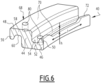
- the inner end portion 46 has, at its free edge, an inner stud 50 projecting radially outwards. It defines, between the stud 50 and the central part 44, an inner groove 52 delimited inwardly by a bottom 54.
- the outer end portion 48 comprises, at its free edge, an additional outer stud 56 projecting inwards.
- the additional stud 56 defines, with the central part 44, an additional external groove 58 delimited towards the outside by an additional bottom 60.
- each turn 42 is clipped into the groove 52 of a second adjacent turn 42B axially opposite the first adjacent turn 42A.
- the stud 50 of the turn 42 defines with the bottom 60 of the groove 58 of the adjacent turn 42A a first helical radial play J1 allowing the passage of gas from the interior of the vault 27 to the outside of the vault 27.
- the bottom 54 of the groove 52 of the turn 42 defines with the additional pin 56 of the adjacent turn 42A, a second helical radial play J2 allowing the passage of gas from the inside of the vault 27 to the outside of the vault 27.
- the radial clearances J1 and J2 are interconnected by a gap 62 inclined between the studs 50 and 56 located opposite.
- the clearance J1 is connected to the space located inside the pressure vault 27 towards the axis A-A' by an internal channel 64 present between the stud 50 of the turn 42 and the central part 44 of the adjacent turn 42A .
- the inner channel 64 opens inwards facing the pressure sheath 20. It therefore receives the gases which diffuse from the inside of the pipe 16 through the pressure sheath 20.
- the clearance J2 is connected to the space located outside the pressure vault 27 with respect to the axis A-A' by an external channel 66 present between the additional stud 56 of the adjacent turn 42A and the central part 44 of the turn 42.
- the outer channel 66 opens outward facing the armor layers 24, 25.
- the inner 64 and outer 66 channels are defined by the intervals between the profiles of the turns 42 and 42A.
- the clearance J1 therefore ensures the passage of gases between the inner channel 64 and the gap 62.
- the clearance J2 ensures the passage of gases between the gap 62 and the outer channel 66.
- At least one clearance J1 and/or J2 is then therefore zero and thus the channels 64, 66 no longer communicate with the gap 62.
- the passage of gases through the stapling of the pressure vault 27 is completely blocked.
- the studs 50, 56 of the turn 42 define at least one additional passage 68, preferably at least one additional passage 68 for the circulation of gas per stud 50, 56 being added to the helical clearance J1 and J2.
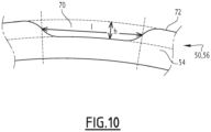
- each additional passage 68 is here defined by a notch 70 made in the free edge 72 of each stud 50, 56.
- Each notch 70 opens out radially outwards or inwards respectively, depending on whether it is on the stud 50 or on the stud 56 respectively. They open axially into the gap 62 and into one of the channels 64, 66 so as to guarantee passage of the gas from the inside to the outside of the layer 40 whatever the size of the clearances J1 and J2, and even if these are completely closed.
- each notch 70 extends only over part of the circumference of the respective stud 50, 56 around the central axis A-A'.
- the width I of the notch 70 in projection in a transverse plane perpendicular to the axis A-A', is advantageously less than 15% of the perimeter of the edge free 72 of the respective stud 50, 56.
- the width I is increased according to the passage surface requirements, which depend on the gas flow rates to be considered.
- the maximum height h of the notch 70 is between 10% and 100% of the height of the stud, taken radially with respect to the central axis A-A' between respectively the bottom 54 of the groove 52 and the free edge 72 of the stud 50 or between the bottom 60 of the groove 58 and the free edge 72 of the stud 56 away from the notch 70.
- each additional passage 68 taken in projection in a transverse plane perpendicular to the axis A-A', preferably corresponds to the surface defined by a clearance J1 or J2 of at least 0.1 mm, in particular greater than 0.2 mm, in particular between 0.1 mm and 0.3 mm.
- this passage surface is adapted on a case-by-case basis according to the gas flow rate to be considered.
- Examples of possible dimensions for the additional passage 68 are described in the table below, corresponding to Z profiles of respective thicknesses e equal to 6.2 mm, 8 mm, 10 mm and 12 mm for internal diameters of arch 27 comprised between 56 mm and 550 mm, for a guaranteed minimum passage surface corresponding to a clearance J1 and J2 of 0.2 mm.
- Smin, Smax and Smoy correspond respectively to the minimum area, to the maximum area and to the average area of a clearance J1 and J2 of 0.2 mm for internal diameters of arch 27 comprised between 56 mm and 550 mm.
- Max h and Max l respectively correspond to examples of height and maximum widths of the notch 70.
- Max S is the surface of the additional passage defined by the notch 70.
- Max S surfaces between 100 mm 2 and 471 mm 2 depending on the size of the profile, are always much higher than the average surfaces represented by J1 or J2 clearances of 0.2 mm.
- the additional passages 68 defined by the notches 70 in the respective studs 50, 56 provide a passage surface for the gases, and prevent their accumulation inside the pressure vault 27.
- the flexible pipe 10 optionally comprises a hoop 73, partially visible on the figure 1 And 2 .
- the hoop 73 when present, is constituted by a spiral winding of at least one wire, advantageously of rectangular cross-section, around the pressure vault 27.
- the superposition of several wires wound around the pressure vault 27 replaces advantageously a given total hoop 73 thickness. This increases the burst strength of the flexible pipe 10.
- the winding of at least one wire is with a short pitch around the axis AA' of the flexible pipe 10, that is to say with an angle helix of absolute value close to 90° with respect to the axis A-A', typically between 75° and 90°.
- the flexible pipe 10 comprises at least one armor layer 24, 25 formed by a helical winding of at least one elongated armor element 74 .
- the flexible pipe 10 comprises a plurality of armor layers 24, 25, in particular an inner armor layer 24, applied to the pressure vault 27 or to the hoop 73, when present, and an outer armor layer 25 around which is arranged the outer sheath 30.
- Each armor layer 24, 25 comprises longitudinal armor elements 74 wound at a long pitch around the axis A-A' of the pipe.
- rolled up with a long pitch it is meant that the absolute value of the helix angle with respect to the axis A-A' is less than 60°, and is typically between 10° and 60°, in particular between 25° and 55°.
- the weave elements 74 of a first layer 24 are wrapped generally at an opposite angle to the weave elements 74 of a second layer 25.
- the angle of wrap of the weave elements 74 of the first layer 24 is equal to + ⁇ , ⁇ being between 10° and 60°
- the winding angle of the armor elements 74 of the second armor layer 25 placed in contact with the first armor layer 24 is for example equal to ⁇ °.
- the armor elements 74 are for example formed by metal wires, in particular steel wires, or by strips of composite material, for example strips reinforced with carbon fibers.
- the metallic material forming the armor elements 74 is advantageously chosen from carbon steel, in particular chosen from carbon steel grades comprising between 0.1% and 0.8% carbon. During applications in a particularly corrosive environment, the metallic material is chosen from stainless steels such as duplex steels.
- each layer of tensile armor 24, 25 advantageously rests on at least one anti-wear strip 75, visible on the figure 1 And 2 .
- the anti-wear strip 75 is for example made of plastic, in particular based on a polyamide, a polyvinylidene fluoride (PVDF), a polyphenylsulfone (PPSU) or even a polyetheretherketone (PEEK). It has a thickness less than the thickness of each internal or external sheath.
- a holding tape such as an aramid tape with high mechanical resistance ( Technora® or Kevlar® ) is wound around the second layer of tensile armor 25 furthest outside with respect to the axis A -A', to provide mechanical support for the tensile armor layers 24, 25.
- the fibers aramid fibers are replaced by glass fibers, carbon fibers or basalt fibers.
- the outer sheath 30 is intended to prevent the penetration of fluid from the outside of the flexible pipe 10 to the inside, in the annular space between the pressure sheath 20 and the outer sheath 30. It is advantageously made of polymer material , in particular based on a polyolefin, such as polyethylene, or based on a polyamide, such as PA11 or PA12.
- the thickness of the outer sheath 30 is for example between 5 mm and 15 mm.
- the dimensions of the pressure vault 27 are determined.
- the type of profiled shaped wire 40 is chosen, and depending on the diameter of the pressure vault 27 desired, the number and size of the additional circulation passages are determined from the passage surface value that a clearance J1 would have. and J2 of the order of 0.2 mm, and may be adapted, that is to say increased or decreased depending on the gas flow which will have to pass through the pressure vault 40.
- Each notch 70 is then made in a stud 50, 56, with the surface corresponding to the determined minimum clearance, this surface being able to vary between 5 mm 2 and 450 mm 2 , in particular between 15 mm 2 and 300 mm 2 , preferentially between 19 mm 2 and 175 mm 2 .
- Each notch 70 is formed by grinding, drilling, and/or by advantageously hot rolling of the profiled wire 40.
- local induction heating is used to produce the notch 70 in the nipple 50, 56.
- the pressure sheath 20 is provided, for example by being extruded.
- the profiled shaped wire 40 here provided with notches 70, is then wound with a short pitch around the pressure sheath 20, by stapling the respective studs 50, 56 in the respective grooves 58, 52, and ensuring that the no manufacturing are within the recommended tolerances so as to ensure a gap 62 and channels 64, 66 that are not zero,
- the armor layers 24, 25 are placed and the outer sheath 30 is provided around the armor layers 24, 25, for example by extrusion.
- At least one additional passage 68 for the circulation of gas is formed by a through hole 80 made in the bottoms of the additional grooves 58, 52.
- a through passage 80 here extends radially through the bottom 60, 54 of each groove 58, 52.
- the holes 80 open radially inward into the groove 58, 52, and radially outward opposite throat 58, 52.
- the dimensions h and l of the hole 80 are represented on the figure 11 .
- the maximum axial dimension h of the through hole 80 is between 10% and 100% of the width of the groove 58, 52.
- the dimension h and the width of the groove 58, 52 are taken in projection on the axis A-A '.
- the length l of the through hole 80, taken in projection on an axis perpendicular to the axis AA' is advantageously less than the maximum clearance between the turns used for dimensioning the creep of the pressure sheath 20, and is determined according to the flow of gas to be passed and according to the number of holes drilled on a circumference.
- the through hole 80 is preferably oblong in shape, being elongated in the circumferential direction.
- the number of through holes 80 made in each groove 58, 52 is greater than 2 through holes 80 per turn 42, and in particular between 2 and 10 through holes 80 per turn 42, for profile sizes with a thickness between 6.2 mm and 12 mm and internal laying diameters between 50 mm and 550 mm.
- Examples of through-hole dimensions 80 are given in the table below for Z profiles of respective thicknesses equal to 6.2 mm, 8 mm, 10 mm and 12 mm.
- Table 2 Imax hole (mm) hmax hole (mm) Stroke (mm2) Z 6.2mm 2.0 1.3 8.5 Z 8mm 2.6 1.7 14.1 Z 10mm 3.3 2.2 22.1 Z 12mm 3.9 2.6 31.8
- the through holes 80 are for example formed by drilling through the grooves 58, 52
- the profiled wire 40 comprises, for each turn 42, at least one additional passage 68 in the form of a notch 70 and at least one additional passage 68 in the form of a hole 80, complementing the notches 70.
- only one of the studs 50, 56 is provided with notches 70, the other stud 56, 50 being devoid of notches 70.
- only one groove 52, 58 is provided with at least one through hole 80, the other groove 58, 52 being devoid of through holes 80.
- waves or successions of smaller notches 70 are made on the studs 50, 56.
- At least one turn of the pressure vault 27 has a T-shaped, U-shaped, K-shaped, X-shaped or i-shaped geometry profile.
- the pressure vault 27 is formed of several profiled shaped wires 40A, 40B, of different sectional profiles, stapled to each other.
- At least one profiled shaped wire 40A has a T-shaped profile. 50, an intermediate groove 52 between the stud 50 and the central region 44.
- the profiled shaped wire 40A is stapled with another profiled shaped wire 40B (generally called a clip) of U-shaped profile. inside on either side of the additional groove 58.
- Each stud 50 of a turn 42 of the shaped wire 40A is received in the additional groove 58 of an adjacent turn of the shaped wire 40B.
- each nipple additional 56 of a turn 42A of the shaped wire 40B is received in the groove 52 of a turn 42 of the shaped wire 40A.
- At least one additional passage 68 for the circulation of gas is provided in the form of a notch 70 in one of the studs 50 of a turn of the shaped wire 40A, and/or in the form of a through hole 80 in the bottom 58 of a turn of the shaped wire 40B, advantageously in the central position.
- At least one 40C-shaped wire has a T-shaped profile and at least one 40D-shaped wire has a K-shaped profile.
- the profile of the wire of form 40C defines an inner stud 50 and an inner groove 52 between the stud 50 and the central part 44.
- the additional shaped wire 40D delimits an additional stud 56 on the outside and an additional groove 58 on the outside between the additional stud 56 and the central part 44.
- Each stud 50 of a turn 42 of the shaped wire 40C is received in the additional groove 58 of an adjacent turn 42A of the shaped wire 40D.
- each additional stud 56 of an adjacent turn 42A of the shaped wire 40D is received in the groove 52 of the turn 42 of the shaped wire 40C.
- an additional passage 68 for the circulation of gas is made in the form of a notch 70 in the studs 50, 56, or/and in the form of a through hole 80 in the bottom 60 of the two grooves 58 of the profile 40D .
- the 40E-shaped wire has a U-shaped profile opening radially outward and the 40F-shaped wire, stapled with the 40E-shaped wire, has a C-shaped profile opening radially outward. interior.
- the profile of the wire of form 40E delimits a central groove 52 and comprises two internal studs 50 projecting outwards on either side of the groove 52.
- the profile of the wire of form 40F has an additional groove 58 and on either side of the additional groove 58, two additional external studs 56 projecting inwards from the additional groove 58.
- Each stud 50 of the shaped yarn 40E is received in an additional groove 58 of the shaped yarn 40F, and each additional stud 56 of the shaped yarn 40F is received in a groove 52 of the shaped yarn 40E.
- At least one additional passage 68 for the circulation of gas is provided in the form of a notch 70 in the studs 50, 56 or in the form of a through hole 80 in the bottom 60 of the groove 58 of the profile 40F, advantageously in the middle.
Landscapes
- Engineering & Computer Science (AREA)
- General Engineering & Computer Science (AREA)
- Mechanical Engineering (AREA)
- Rigid Pipes And Flexible Pipes (AREA)
Claims (15)
- Flexible Leitung (10) für Fluidtransport, umfassend:- eine rohrförmige Hülle (20) aus Polymer, die einen Durchgang (16) für Fluidzirkulation mit einer Mittelachse (A-A') begrenzt;- ein Druckgewölbe (27), das um und außerhalb der rohrförmigen Hülle (20) angeordnet ist, wobei das Druckgewölbe (27) eine Wicklung mit kurzer Steigung von mindestens einem geklammerten Formdraht (40; 40A; 40C; 40E) umfasst, wobei der Formdraht (40; 40A; 40C; 40E) eine Vielzahl von geklammerten Windungen (42) aufweist, wobei jede Windung (42) im Querschnitt in einer axialen Mittelebene ein Profil aufweist, das mindestens einen Zapfen (50, 56) und für den oder jeden Zapfen (50, 56) eine Nut (52, 58) neben dem Zapfen (50, 56) definiert, wobei der Zapfen (50, 56) dazu geeignet ist, in eine Nut (58, 52) einer benachbarten Windung eines Formdrahts (40; 40B; 40D; 40F) der Druckgewölbe (27) geklammert zu werden;- mindestens eine Bewehrungsschicht (24, 25) außerhalb des Druckgewölbes (27),dadurch gekennzeichnet, dass mindestens ein zusätzlicher Durchgang (68) für Gaszirkulation durch das Druckgewölbe (27) von der Innenseite des Druckgewölbes (27) zu der Außenseite des Druckgewölbes (27) in dem oder jedem Zapfen (50, 56) und/oder in dem Boden (60, 54) der oder jeder Nut (58, 52) definiert ist, wobei der zusätzliche Durchgang (68), die Gaszirkulation von Gas zwischen der Innenseite des Druckgewölbes (27) und der Außenseite des Druckgewölbes (27) ermöglicht, zusätzlich zu mindestens einem Spielraum (J1, J2) zwischen dem Zapfen (50, 56) einer Windung (42) und dem Boden (60, 54) der Nut (58, 52) der benachbarten Windung oder bei Fehlen eines Spielraums (J1, J2) zwischen dem Zapfen (50, 56) einer Windung (42) und dem Boden (60, 54) der Nut (58, 52) der benachbarten Windung.
- Leitung (10) nach Anspruch 1, wobei das Profil jeder Windung (42) im Querschnitt in einer axialen Mittelebene einen Zapfen (50) und eine Nut (52) neben dem Zapfen (50) definiert, wobei der Zapfen (50) geeignet ist, in eine Nut (58) einer benachbarten Windung eines Formdrahts (40; 40B; 40D; 40F) des Druckgewölbes (27) geklammert zu werden, wobei das Profil jeder Windung (42) im Querschnitt in einer axialen Mittelebene einen zusätzlichen Zapfen (56) und eine zusätzliche Nut (58) benachbart zu dem zusätzlichen Zapfen (56) definiert, wobei der zusätzliche Zapfen (56) geeignet ist, um in eine Nut (52) einer gegenüberliegenden benachbarten Windung eines Formdrahts (40; 40B; 40D; 40F) des Druckgewölbes (27), das sich gegenüber der benachbarten Windung befindet, geklammert zu werden, wobei mindestens ein zusätzlicher Durchgang (68) für Gaszirkulation durch die Druckgewölbe (27) von der Innenseite des Druckgewölbes (27) zu der Außenseite des Druckgewölbes (27) in jedem Zapfen (50, 56) und/oder im Boden (60, 54) jeder Nut (58, 52) definiert ist, wobei jeder zusätzliche Durchgang (68) die Gaszirkulation zwischen der Innenseite des Druckgewölbes (27) und der Außenseite des Druckgewölbes (27) ermöglicht.
- Leitung (10) nach Anspruch 1 oder 2, wobei die kumulierte Fläche des oder der zusätzlichen Durchgänge (68), in einer Projektion in einer Querebene betrachtet, der Fläche entspricht, die durch ein Spiel (J1, J2) größer als 0,1 mm zwischen dem Zapfen (50, 56) einer Windung und dem Boden (60, 54) der Nut (58, 52) der benachbarten Windung definiert ist.
- Leitung (10) nach Anspruch 3, wobei die kumulierte Fläche des oder der zusätzlichen Durchgänge (68), in einer Projektion in einer Querebene betrachtet, der Fläche entspricht, die durch ein Spiel (J1, J2) zwischen 0,1 mm und 0,3 mm zwischen dem Zapfen (50, 56) einer Windung und dem Boden (60, 54) der Nut (58, 52) der benachbarten Windung definiert ist und vorteilhafterweise zwischen 9 mm2 und 262 mm2 liegt.
- Leitung (10) nach einem der vorherigen Ansprüche, wobei mindestens ein zusätzlicher Durchgang (68) durch eine Kerbe (70) gebildet ist, die in dem oder jedem Zapfen (50, 56) gebildet ist.
- Leitung (10) nach Anspruch 5, wobei die Breite der Kerbe (70), die in dem oder jedem Zapfen (50, 56) gebildet ist, weniger als 15 % des Umfangs des freien Rands (72) des Zapfens (50, 56) ist.
- Leitung (10) nach einem der Ansprüche 5 oder 6, wobei die Höhe der Kerbe (70), radial genommen in Bezug auf die Mittelachse (A-A') zwischen dem Boden (54, 60) der Nut (52, 58) und dem freien Rand (72) des Zapfens (50, 56) im Abstand von der Kerbe (70), zwischen 10 % und 100 % der Höhe des Zapfens (50, 56) ist.
- Leitung (10) nach einem der vorherigen Ansprüche, wobei mindestens ein zusätzlicher Durchgang (68) durch ein Durchgangsloch (80) gebildet ist, das im Boden (60, 54) der oder jeder Nut (58, 52) ausgebildet ist.
- Leitung (10) nach Anspruch 8, wobei sich das Durchgangsloch (80) radial durch den Boden (60, 54) der oder jeder Nut (58, 52) erstreckt.
- Leitung (10) nach Anspruch 8 oder 9, wobei die maximale axiale Abmessung des Durchgangslochs (80), projiziert auf die Mittelachse (A-A'), quer zu der Mittelachse (A-A') betrachtet, kleiner ist als die Breite des Durchgangslochs (80).
- Leitung (10) nach einem der Ansprüche 8 bis 10, wobei die maximale axiale Abmessung des Durchgangslochs (80) weniger als 100 % der maximalen axialen Abmessung der oder jeder Nut (58, 52) ist, wobei die axialen Abmessungen als Projektion auf die Mittelachse (A-A') genommen werden.
- Leitung (10) nach einem der vorherigen Ansprüche, wobei das Profil des Formdrahts (40; 40A; 40C; 40E) ausgewählt ist aus einem Z-, T-, Ψ- und C-Querschnittsprofil.
- Verfahren zur Herstellung einer flexiblen Leitung (10), umfassend die folgenden Schritte:- Bereitstellen einer rohrförmigen Hülle (20) aus Polymer, die einen Durchgang (16) für Fluidzirkulation mit einer Mittelachse (A-A') begrenzt;- Bilden eines Druckgewölbes (27) um die rohrförmige Hülle (20), das Bilden umfassend ein Wickeln mit kurzer Steigung und ein Klammern von mindestens einem Formdraht (40; 40A; 40C; 40E), wobei der Formdraht (40; 40A; 40C; 40E) eine Vielzahl von gehefteten Windungen (42) aufweist, wobei jede Windung (42) im Querschnitt in einer axialen Mittelebene ein Profil aufweist, das mindestens einen Zapfen (50, 56) und für den oder jeden Zapfen (50, 56) eine Nut (52, 58) neben dem Zapfen (50, 56) definiert, wobei der Zapfen (50, 56) dazu geeignet ist, in eine Nut (58, 52) einer benachbarten Windung eines Formdrahts (40; 40B; 40D; 40F) der Druckgewölbe (27) geklammert zu werden;- Anordnen mindestens einer Bewehrungsschicht (24, 25) außerhalb des Druckgewölbes (27),dadurch gekennzeichnet, dass mindestens ein zusätzlicher Durchgang (68) für Gaszirkulation durch das Druckgewölbe (27) von der Innenseite des Druckgewölbes (27) zu der Außenseite des Druckgewölbes (27) in dem oder jedem Zapfen (50, 56) und/oder in dem Boden (60, 54) der oder jeder Nut (58, 52) definiert ist, wobei der zusätzliche Durchgang (68), die Gaszirkulation von Gas zwischen der Innenseite des Druckgewölbes (27) und der Außenseite des Druckgewölbes (27) ermöglicht, zusätzlich zu mindestens einem Spielraum (J1, J2) zwischen dem Zapfen (50, 56) einer Windung (42) und dem Boden (60, 54) der Nut (58, 52) der benachbarten Windung oder bei Fehlen eines Spielraums (J1, J2) zwischen dem Zapfen (50, 56) einer Windung (42) und dem Boden (60, 54) der Nut (58, 52) der benachbarten Windung.
- Verfahren nach Anspruch 13, wobei der oder jeder zusätzliche Durchgang (68) für Zirkulation durch Herstellen einer Kerbe (70) in dem oder jedem Zapfen (50, 56) und/oder durch Herstellen eines Durchgangslochs (80) durch den Boden (60, 54) der oder jeder Nut (58, 52) gebildet ist.
- Verwendung einer flexiblen Leitung (10) nach einem der Ansprüche 1 bis 12 zum Transport von Fluid durch den Durchgang (16) für Fluidzirkulation, die Verwendung umfassend die Diffusion eines in dem Fluid enthaltenen Gases durch die rohrförmige Hülle (20) und dann durch das Druckgewölbe (27), durch den oder jeden zusätzlichen Durchgang (68), von der Innenseite des Druckgewölbes (27) zu der Außenseite des Druckgewölbes (27).
Applications Claiming Priority (2)
| Application Number | Priority Date | Filing Date | Title |
|---|---|---|---|
| FR1909479A FR3100303B1 (fr) | 2019-08-28 | 2019-08-28 | Conduite flexible avec passage de gaz radial, procédé de fabrication et utilisation associée |
| PCT/EP2020/073835 WO2021037902A1 (fr) | 2019-08-28 | 2020-08-26 | Conduite flexible avec passage de gaz radial, procédé de fabrication et utilisation associée |
Publications (2)
| Publication Number | Publication Date |
|---|---|
| EP4022210A1 EP4022210A1 (de) | 2022-07-06 |
| EP4022210B1 true EP4022210B1 (de) | 2023-07-19 |
Family
ID=68138565
Family Applications (1)
| Application Number | Title | Priority Date | Filing Date |
|---|---|---|---|
| EP20765221.5A Active EP4022210B1 (de) | 2019-08-28 | 2020-08-26 | Flexibles rohr mit radialgaskanal, herstellungsverfahren und verwendung davon |
Country Status (8)
| Country | Link |
|---|---|
| US (1) | US12228223B2 (de) |
| EP (1) | EP4022210B1 (de) |
| CN (1) | CN114341539B (de) |
| AU (1) | AU2020339699B2 (de) |
| DK (1) | DK4022210T3 (de) |
| FR (1) | FR3100303B1 (de) |
| MY (1) | MY210581A (de) |
| WO (1) | WO2021037902A1 (de) |
Family Cites Families (27)
| Publication number | Priority date | Publication date | Assignee | Title |
|---|---|---|---|---|
| GB1294227A (en) * | 1970-01-23 | 1972-10-25 | Trevor Frederick Moss | Improvements in or relating to flexible tubing |
| US3682203A (en) * | 1970-01-23 | 1972-08-08 | Federal Metal Hose Corp The | Flexible metal hose |
| US5645109A (en) * | 1990-06-29 | 1997-07-08 | Coflexip | Flexible tubular pipe comprising an interlocked armoring web and process for producing it |
| US5730188A (en) * | 1996-10-11 | 1998-03-24 | Wellstream, Inc. | Flexible conduit |
| US6769454B2 (en) * | 1999-11-05 | 2004-08-03 | Wellstream International Limited | Flexible pipe including a vent passage and method of manufacturing same |
| DK200001707A (da) * | 2000-04-25 | 2000-11-15 | Nkt Flexibles Is | Armeret fleksibelt rør samt anvendelse af samme |
| FR2824124B1 (fr) * | 2001-04-27 | 2003-09-19 | Inst Francais Du Petrole | Tube en materiau composite comportant une carcasse interne |
| FR2824890B1 (fr) * | 2001-05-18 | 2004-04-16 | Coflexip | Conduite flexible a voute agrafee par le bas |
| US6543488B2 (en) * | 2001-06-21 | 2003-04-08 | Hose Master, Inc. | Flexible metal hose |
| FR2846395B1 (fr) * | 2002-10-25 | 2005-05-13 | Coflexip | Conduite tubulaire flexible pour le transport d'un fluide |
| FR2852658B1 (fr) | 2003-03-21 | 2005-04-22 | Coflexip | Conduite tubulaire flexible pour le transport d'un fluide |
| FR2895059B1 (fr) * | 2005-12-20 | 2008-02-22 | Hutchinson Sa | Attenuateur de bruit pour flexible hydraulique, flexible qui en est pourvu et systeme de direction assistee l'incorporant |
| GB0712586D0 (en) * | 2007-06-28 | 2007-08-08 | Wellstream Int Ltd | Flexible pipe |
| GB0800155D0 (en) * | 2008-01-07 | 2008-02-13 | Wellstream Int Ltd | Flexible pipe having pressure armour layer |
| GB0922120D0 (en) * | 2009-12-18 | 2010-02-03 | Wellstream Int Ltd | Flexible pipe including carcass layer |
| FR2989144B1 (fr) * | 2012-04-04 | 2014-05-09 | Technip France | Assemblage d'une conduite tubulaire flexible pour le transport de fluides d'hydrocarbures avec un tube metallique secondaire |
| MY178414A (en) * | 2012-08-07 | 2020-10-12 | Baker Hughes Energy Technology UK Ltd | Flexible pipe body and method of providing the same |
| FR3006414B1 (fr) * | 2013-05-29 | 2015-07-03 | Technip France | Conduite flexible de transport de fluide, utilisation et procede associes |
| FR3017438B1 (fr) | 2014-02-11 | 2016-10-14 | Technip France | Conduite flexible de transport de fluide et procede associe |
| US10203053B2 (en) * | 2014-10-03 | 2019-02-12 | Hose Master Llc | Fluid permeable hose carcass |
| CN105526436B (zh) * | 2015-07-15 | 2018-06-12 | 江阴市康乐塑胶有限公司 | 内肋外筋增强波纹管 |
| FR3046210B1 (fr) * | 2015-12-29 | 2018-02-02 | Technip France | Embout de connexion d'une ligne flexible, ligne flexible et procede de montage associes |
| BR112019000076B1 (pt) | 2016-07-06 | 2022-05-17 | National Oilwell Varco Denmark I/S | Tubo flexível blindado com uma camada de retenção de tira metálica alongada |
| CN205978873U (zh) * | 2016-08-29 | 2017-02-22 | 长沙成进汽车配件有限公司 | 一种汽车柔性管件 |
| CN108527807B (zh) * | 2018-04-04 | 2020-03-27 | 中国石油大学(北京) | 一种非金属柔性管及其制造方法 |
| CN208735049U (zh) * | 2018-09-07 | 2019-04-12 | 广州远和船海研究院有限公司 | 一种海洋用柔性管的骨架层和复合柔性管 |
| CN109027451B (zh) * | 2018-10-30 | 2020-08-07 | 台州市路桥三阳泰洁具有限公司 | 一种热水输送软管 |
-
2019
- 2019-08-28 FR FR1909479A patent/FR3100303B1/fr not_active Expired - Fee Related
-
2020
- 2020-08-26 EP EP20765221.5A patent/EP4022210B1/de active Active
- 2020-08-26 US US17/638,010 patent/US12228223B2/en active Active
- 2020-08-26 DK DK20765221.5T patent/DK4022210T3/da active
- 2020-08-26 MY MYPI2022000912A patent/MY210581A/en unknown
- 2020-08-26 CN CN202080060754.XA patent/CN114341539B/zh active Active
- 2020-08-26 WO PCT/EP2020/073835 patent/WO2021037902A1/fr not_active Ceased
- 2020-08-26 AU AU2020339699A patent/AU2020339699B2/en active Active
Also Published As
| Publication number | Publication date |
|---|---|
| WO2021037902A1 (fr) | 2021-03-04 |
| BR112022003231A2 (pt) | 2022-05-17 |
| FR3100303A1 (fr) | 2021-03-05 |
| AU2020339699A1 (en) | 2022-03-10 |
| DK4022210T3 (da) | 2023-10-16 |
| CN114341539A (zh) | 2022-04-12 |
| US20220275884A1 (en) | 2022-09-01 |
| FR3100303B1 (fr) | 2021-07-30 |
| CN114341539B (zh) | 2023-04-04 |
| MY210581A (en) | 2025-10-01 |
| EP4022210A1 (de) | 2022-07-06 |
| US12228223B2 (en) | 2025-02-18 |
| AU2020339699B2 (en) | 2025-06-26 |
Similar Documents
| Publication | Publication Date | Title |
|---|---|---|
| EP3717817B1 (de) | Anschlussendstück für ein flexibles rohr zum transport von flüssigkeit, zugehöriges rohr und verfahren | |
| FR2971829A1 (fr) | Conduite tubulaire flexible pour le transport d'un fluide petrolier tel qu'un fluide polyphasique ou un gaz. | |
| EP3692295B1 (de) | Befestigungsendstück für ein flexibles rohr, zugehöriges flexibles rohr und zugehöriges verfahren | |
| EP4298365B1 (de) | Flexibles rohr mit mindestens einer schräg verlaufenden gaszirkulationsöffnung und zugehöriges herstellungsverfahren | |
| WO2022096748A1 (fr) | Conduite flexible de transport de fluide et procédés associés | |
| EP3987208B1 (de) | Flexibles rohr zum transport von flüssigkeit mit einem schraubenförmigen einsatz sowie zugehöriges verfahren | |
| WO2021037902A1 (fr) | Conduite flexible avec passage de gaz radial, procédé de fabrication et utilisation associée | |
| EP4285044B1 (de) | Flexibles rohr zur förderung eines fluids und zugehöriges herstellungsverfahren | |
| EP4073411B1 (de) | Verbindungsendstück und flexibles rohr, zusammenbau und zugehöriges verfahren | |
| WO2020120700A1 (fr) | Procédé de fabrication d'une conduite flexible et conduite associée | |
| WO2025219451A1 (fr) | Conduite flexible de transport de fluide comportant une surface interne lisse et procédé de fabrication associé | |
| WO2020128001A1 (fr) | Conduite flexible pour le transport d'un fluide en milieu sous-marin et procédé associé | |
| EP3899339B1 (de) | Flexibles rohr zum fördern eines fluids in einer unterwasserumgebung und zugehöriges verfahren | |
| BR112022003231B1 (pt) | Tubo flexível de transporte de fluido, método para fabricar um tubo flexível e uso de um tubo flexível | |
| BR112023017085B1 (pt) | Tubo flexível para transporte de fluido e método de fabricação de um tubo flexível | |
| WO2026099331A1 (fr) | Embout de conduite flexible de transport de fluide, conduite flexible et procédé associé | |
| FR3168248A1 (fr) | Embout de conduite flexible de transport de fluide, conduite flexible et procédé associé | |
| FR3086365A1 (fr) | Conduite flexible, destinee a etre immergee dans une etendue d'eau, et procede de fabrication associe | |
| FR3104667A1 (fr) | Conduite flexible sous-marine comprenant une couche comprenant du polyméthylpentène |
Legal Events
| Date | Code | Title | Description |
|---|---|---|---|
| STAA | Information on the status of an ep patent application or granted ep patent |
Free format text: STATUS: UNKNOWN |
|
| STAA | Information on the status of an ep patent application or granted ep patent |
Free format text: STATUS: THE INTERNATIONAL PUBLICATION HAS BEEN MADE |
|
| PUAI | Public reference made under article 153(3) epc to a published international application that has entered the european phase |
Free format text: ORIGINAL CODE: 0009012 |
|
| STAA | Information on the status of an ep patent application or granted ep patent |
Free format text: STATUS: REQUEST FOR EXAMINATION WAS MADE |
|
| 17P | Request for examination filed |
Effective date: 20220225 |
|
| AK | Designated contracting states |
Kind code of ref document: A1 Designated state(s): AL AT BE BG CH CY CZ DE DK EE ES FI FR GB GR HR HU IE IS IT LI LT LU LV MC MK MT NL NO PL PT RO RS SE SI SK SM TR |
|
| DAV | Request for validation of the european patent (deleted) | ||
| DAX | Request for extension of the european patent (deleted) | ||
| GRAP | Despatch of communication of intention to grant a patent |
Free format text: ORIGINAL CODE: EPIDOSNIGR1 |
|
| STAA | Information on the status of an ep patent application or granted ep patent |
Free format text: STATUS: GRANT OF PATENT IS INTENDED |
|
| INTG | Intention to grant announced |
Effective date: 20230210 |
|
| GRAS | Grant fee paid |
Free format text: ORIGINAL CODE: EPIDOSNIGR3 |
|
| GRAA | (expected) grant |
Free format text: ORIGINAL CODE: 0009210 |
|
| STAA | Information on the status of an ep patent application or granted ep patent |
Free format text: STATUS: THE PATENT HAS BEEN GRANTED |
|
| RAP3 | Party data changed (applicant data changed or rights of an application transferred) |
Owner name: TECHNIPFMC SUBSEA FRANCE |
|
| P01 | Opt-out of the competence of the unified patent court (upc) registered |
Effective date: 20230531 |
|
| AK | Designated contracting states |
Kind code of ref document: B1 Designated state(s): AL AT BE BG CH CY CZ DE DK EE ES FI FR GB GR HR HU IE IS IT LI LT LU LV MC MK MT NL NO PL PT RO RS SE SI SK SM TR |
|
| REG | Reference to a national code |
Ref country code: GB Ref legal event code: FG4D Free format text: NOT ENGLISH |
|
| REG | Reference to a national code |
Ref country code: CH Ref legal event code: EP |
|
| REG | Reference to a national code |
Ref country code: DE Ref legal event code: R096 Ref document number: 602020014139 Country of ref document: DE |
|
| REG | Reference to a national code |
Ref country code: IE Ref legal event code: FG4D Free format text: LANGUAGE OF EP DOCUMENT: FRENCH |
|
| REG | Reference to a national code |
Ref country code: DK Ref legal event code: T3 Effective date: 20231010 |
|
| REG | Reference to a national code |
Ref country code: NO Ref legal event code: T2 Effective date: 20230719 |
|
| REG | Reference to a national code |
Ref country code: LT Ref legal event code: MG9D |
|
| REG | Reference to a national code |
Ref country code: NL Ref legal event code: MP Effective date: 20230719 |
|
| REG | Reference to a national code |
Ref country code: AT Ref legal event code: MK05 Ref document number: 1589787 Country of ref document: AT Kind code of ref document: T Effective date: 20230719 |
|
| PG25 | Lapsed in a contracting state [announced via postgrant information from national office to epo] |
Ref country code: NL Free format text: LAPSE BECAUSE OF FAILURE TO SUBMIT A TRANSLATION OF THE DESCRIPTION OR TO PAY THE FEE WITHIN THE PRESCRIBED TIME-LIMIT Effective date: 20230719 |
|
| PG25 | Lapsed in a contracting state [announced via postgrant information from national office to epo] |
Ref country code: GR Free format text: LAPSE BECAUSE OF FAILURE TO SUBMIT A TRANSLATION OF THE DESCRIPTION OR TO PAY THE FEE WITHIN THE PRESCRIBED TIME-LIMIT Effective date: 20231020 |
|
| PG25 | Lapsed in a contracting state [announced via postgrant information from national office to epo] |
Ref country code: IS Free format text: LAPSE BECAUSE OF FAILURE TO SUBMIT A TRANSLATION OF THE DESCRIPTION OR TO PAY THE FEE WITHIN THE PRESCRIBED TIME-LIMIT Effective date: 20231119 |
|
| PG25 | Lapsed in a contracting state [announced via postgrant information from national office to epo] |
Ref country code: SE Free format text: LAPSE BECAUSE OF FAILURE TO SUBMIT A TRANSLATION OF THE DESCRIPTION OR TO PAY THE FEE WITHIN THE PRESCRIBED TIME-LIMIT Effective date: 20230719 Ref country code: RS Free format text: LAPSE BECAUSE OF FAILURE TO SUBMIT A TRANSLATION OF THE DESCRIPTION OR TO PAY THE FEE WITHIN THE PRESCRIBED TIME-LIMIT Effective date: 20230719 Ref country code: PT Free format text: LAPSE BECAUSE OF FAILURE TO SUBMIT A TRANSLATION OF THE DESCRIPTION OR TO PAY THE FEE WITHIN THE PRESCRIBED TIME-LIMIT Effective date: 20231120 Ref country code: LV Free format text: LAPSE BECAUSE OF FAILURE TO SUBMIT A TRANSLATION OF THE DESCRIPTION OR TO PAY THE FEE WITHIN THE PRESCRIBED TIME-LIMIT Effective date: 20230719 Ref country code: LT Free format text: LAPSE BECAUSE OF FAILURE TO SUBMIT A TRANSLATION OF THE DESCRIPTION OR TO PAY THE FEE WITHIN THE PRESCRIBED TIME-LIMIT Effective date: 20230719 Ref country code: IS Free format text: LAPSE BECAUSE OF FAILURE TO SUBMIT A TRANSLATION OF THE DESCRIPTION OR TO PAY THE FEE WITHIN THE PRESCRIBED TIME-LIMIT Effective date: 20231119 Ref country code: HR Free format text: LAPSE BECAUSE OF FAILURE TO SUBMIT A TRANSLATION OF THE DESCRIPTION OR TO PAY THE FEE WITHIN THE PRESCRIBED TIME-LIMIT Effective date: 20230719 Ref country code: GR Free format text: LAPSE BECAUSE OF FAILURE TO SUBMIT A TRANSLATION OF THE DESCRIPTION OR TO PAY THE FEE WITHIN THE PRESCRIBED TIME-LIMIT Effective date: 20231020 Ref country code: FI Free format text: LAPSE BECAUSE OF FAILURE TO SUBMIT A TRANSLATION OF THE DESCRIPTION OR TO PAY THE FEE WITHIN THE PRESCRIBED TIME-LIMIT Effective date: 20230719 Ref country code: AT Free format text: LAPSE BECAUSE OF FAILURE TO SUBMIT A TRANSLATION OF THE DESCRIPTION OR TO PAY THE FEE WITHIN THE PRESCRIBED TIME-LIMIT Effective date: 20230719 |
|
| PG25 | Lapsed in a contracting state [announced via postgrant information from national office to epo] |
Ref country code: PL Free format text: LAPSE BECAUSE OF FAILURE TO SUBMIT A TRANSLATION OF THE DESCRIPTION OR TO PAY THE FEE WITHIN THE PRESCRIBED TIME-LIMIT Effective date: 20230719 |
|
| REG | Reference to a national code |
Ref country code: DE Ref legal event code: R119 Ref document number: 602020014139 Country of ref document: DE |
|
| REG | Reference to a national code |
Ref country code: CH Ref legal event code: PL |
|
| PG25 | Lapsed in a contracting state [announced via postgrant information from national office to epo] |
Ref country code: LU Free format text: LAPSE BECAUSE OF NON-PAYMENT OF DUE FEES Effective date: 20230826 |
|
| PG25 | Lapsed in a contracting state [announced via postgrant information from national office to epo] |
Ref country code: ES Free format text: LAPSE BECAUSE OF FAILURE TO SUBMIT A TRANSLATION OF THE DESCRIPTION OR TO PAY THE FEE WITHIN THE PRESCRIBED TIME-LIMIT Effective date: 20230719 |
|
| PG25 | Lapsed in a contracting state [announced via postgrant information from national office to epo] |
Ref country code: SM Free format text: LAPSE BECAUSE OF FAILURE TO SUBMIT A TRANSLATION OF THE DESCRIPTION OR TO PAY THE FEE WITHIN THE PRESCRIBED TIME-LIMIT Effective date: 20230719 Ref country code: RO Free format text: LAPSE BECAUSE OF FAILURE TO SUBMIT A TRANSLATION OF THE DESCRIPTION OR TO PAY THE FEE WITHIN THE PRESCRIBED TIME-LIMIT Effective date: 20230719 Ref country code: LU Free format text: LAPSE BECAUSE OF NON-PAYMENT OF DUE FEES Effective date: 20230826 Ref country code: ES Free format text: LAPSE BECAUSE OF FAILURE TO SUBMIT A TRANSLATION OF THE DESCRIPTION OR TO PAY THE FEE WITHIN THE PRESCRIBED TIME-LIMIT Effective date: 20230719 Ref country code: EE Free format text: LAPSE BECAUSE OF FAILURE TO SUBMIT A TRANSLATION OF THE DESCRIPTION OR TO PAY THE FEE WITHIN THE PRESCRIBED TIME-LIMIT Effective date: 20230719 Ref country code: CZ Free format text: LAPSE BECAUSE OF FAILURE TO SUBMIT A TRANSLATION OF THE DESCRIPTION OR TO PAY THE FEE WITHIN THE PRESCRIBED TIME-LIMIT Effective date: 20230719 Ref country code: MC Free format text: LAPSE BECAUSE OF FAILURE TO SUBMIT A TRANSLATION OF THE DESCRIPTION OR TO PAY THE FEE WITHIN THE PRESCRIBED TIME-LIMIT Effective date: 20230719 Ref country code: SK Free format text: LAPSE BECAUSE OF FAILURE TO SUBMIT A TRANSLATION OF THE DESCRIPTION OR TO PAY THE FEE WITHIN THE PRESCRIBED TIME-LIMIT Effective date: 20230719 Ref country code: CH Free format text: LAPSE BECAUSE OF NON-PAYMENT OF DUE FEES Effective date: 20230831 |
|
| REG | Reference to a national code |
Ref country code: BE Ref legal event code: MM Effective date: 20230831 |
|
| REG | Reference to a national code |
Ref country code: IE Ref legal event code: MM4A |
|
| PLBE | No opposition filed within time limit |
Free format text: ORIGINAL CODE: 0009261 |
|
| STAA | Information on the status of an ep patent application or granted ep patent |
Free format text: STATUS: NO OPPOSITION FILED WITHIN TIME LIMIT |
|
| PG25 | Lapsed in a contracting state [announced via postgrant information from national office to epo] |
Ref country code: IT Free format text: LAPSE BECAUSE OF FAILURE TO SUBMIT A TRANSLATION OF THE DESCRIPTION OR TO PAY THE FEE WITHIN THE PRESCRIBED TIME-LIMIT Effective date: 20230719 |
|
| 26N | No opposition filed |
Effective date: 20240422 |
|
| PG25 | Lapsed in a contracting state [announced via postgrant information from national office to epo] |
Ref country code: IE Free format text: LAPSE BECAUSE OF NON-PAYMENT OF DUE FEES Effective date: 20230826 |
|
| PG25 | Lapsed in a contracting state [announced via postgrant information from national office to epo] |
Ref country code: IE Free format text: LAPSE BECAUSE OF NON-PAYMENT OF DUE FEES Effective date: 20230826 Ref country code: DE Free format text: LAPSE BECAUSE OF NON-PAYMENT OF DUE FEES Effective date: 20240301 Ref country code: SI Free format text: LAPSE BECAUSE OF FAILURE TO SUBMIT A TRANSLATION OF THE DESCRIPTION OR TO PAY THE FEE WITHIN THE PRESCRIBED TIME-LIMIT Effective date: 20230719 |
|
| PG25 | Lapsed in a contracting state [announced via postgrant information from national office to epo] |
Ref country code: BE Free format text: LAPSE BECAUSE OF NON-PAYMENT OF DUE FEES Effective date: 20230831 |
|
| PG25 | Lapsed in a contracting state [announced via postgrant information from national office to epo] |
Ref country code: BG Free format text: LAPSE BECAUSE OF FAILURE TO SUBMIT A TRANSLATION OF THE DESCRIPTION OR TO PAY THE FEE WITHIN THE PRESCRIBED TIME-LIMIT Effective date: 20230719 |
|
| PG25 | Lapsed in a contracting state [announced via postgrant information from national office to epo] |
Ref country code: BG Free format text: LAPSE BECAUSE OF FAILURE TO SUBMIT A TRANSLATION OF THE DESCRIPTION OR TO PAY THE FEE WITHIN THE PRESCRIBED TIME-LIMIT Effective date: 20230719 |
|
| PG25 | Lapsed in a contracting state [announced via postgrant information from national office to epo] |
Ref country code: CY Free format text: LAPSE BECAUSE OF FAILURE TO SUBMIT A TRANSLATION OF THE DESCRIPTION OR TO PAY THE FEE WITHIN THE PRESCRIBED TIME-LIMIT; INVALID AB INITIO Effective date: 20200826 |
|
| PG25 | Lapsed in a contracting state [announced via postgrant information from national office to epo] |
Ref country code: HU Free format text: LAPSE BECAUSE OF FAILURE TO SUBMIT A TRANSLATION OF THE DESCRIPTION OR TO PAY THE FEE WITHIN THE PRESCRIBED TIME-LIMIT; INVALID AB INITIO Effective date: 20200826 |
|
| PGFP | Annual fee paid to national office [announced via postgrant information from national office to epo] |
Ref country code: DK Payment date: 20250729 Year of fee payment: 6 |
|
| PGFP | Annual fee paid to national office [announced via postgrant information from national office to epo] |
Ref country code: NO Payment date: 20250728 Year of fee payment: 6 |
|
| PGFP | Annual fee paid to national office [announced via postgrant information from national office to epo] |
Ref country code: GB Payment date: 20250826 Year of fee payment: 6 |
|
| PGFP | Annual fee paid to national office [announced via postgrant information from national office to epo] |
Ref country code: FR Payment date: 20250825 Year of fee payment: 6 |
|
| PG25 | Lapsed in a contracting state [announced via postgrant information from national office to epo] |
Ref country code: TR Free format text: LAPSE BECAUSE OF FAILURE TO SUBMIT A TRANSLATION OF THE DESCRIPTION OR TO PAY THE FEE WITHIN THE PRESCRIBED TIME-LIMIT Effective date: 20230719 |