EP4022178B1 - Verfahren zum einstellen einer temperatur einer komponente eines abgassystems - Google Patents
Verfahren zum einstellen einer temperatur einer komponente eines abgassystems Download PDFInfo
- Publication number
- EP4022178B1 EP4022178B1 EP20740292.6A EP20740292A EP4022178B1 EP 4022178 B1 EP4022178 B1 EP 4022178B1 EP 20740292 A EP20740292 A EP 20740292A EP 4022178 B1 EP4022178 B1 EP 4022178B1
- Authority
- EP
- European Patent Office
- Prior art keywords
- temperature
- exhaust gas
- component
- gas system
- catalytic converter
- Prior art date
- Legal status (The legal status is an assumption and is not a legal conclusion. Google has not performed a legal analysis and makes no representation as to the accuracy of the status listed.)
- Active
Links
Images

Classifications
-
- F—MECHANICAL ENGINEERING; LIGHTING; HEATING; WEAPONS; BLASTING
- F01—MACHINES OR ENGINES IN GENERAL; ENGINE PLANTS IN GENERAL; STEAM ENGINES
- F01N—GAS-FLOW SILENCERS OR EXHAUST APPARATUS FOR MACHINES OR ENGINES IN GENERAL; GAS-FLOW SILENCERS OR EXHAUST APPARATUS FOR INTERNAL-COMBUSTION ENGINES
- F01N9/00—Electrical control of exhaust gas treating apparatus
- F01N9/005—Electrical control of exhaust gas treating apparatus using models instead of sensors to determine operating characteristics of exhaust systems, e.g. calculating catalyst temperature instead of measuring it directly
-
- F—MECHANICAL ENGINEERING; LIGHTING; HEATING; WEAPONS; BLASTING
- F01—MACHINES OR ENGINES IN GENERAL; ENGINE PLANTS IN GENERAL; STEAM ENGINES
- F01N—GAS-FLOW SILENCERS OR EXHAUST APPARATUS FOR MACHINES OR ENGINES IN GENERAL; GAS-FLOW SILENCERS OR EXHAUST APPARATUS FOR INTERNAL-COMBUSTION ENGINES
- F01N11/00—Monitoring or diagnostic devices for exhaust-gas treatment apparatus
- F01N11/002—Monitoring or diagnostic devices for exhaust-gas treatment apparatus the diagnostic devices measuring or estimating temperature or pressure in, or downstream of the exhaust apparatus
- F01N11/005—Monitoring or diagnostic devices for exhaust-gas treatment apparatus the diagnostic devices measuring or estimating temperature or pressure in, or downstream of the exhaust apparatus the temperature or pressure being estimated, e.g. by means of a theoretical model
-
- F—MECHANICAL ENGINEERING; LIGHTING; HEATING; WEAPONS; BLASTING
- F01—MACHINES OR ENGINES IN GENERAL; ENGINE PLANTS IN GENERAL; STEAM ENGINES
- F01N—GAS-FLOW SILENCERS OR EXHAUST APPARATUS FOR MACHINES OR ENGINES IN GENERAL; GAS-FLOW SILENCERS OR EXHAUST APPARATUS FOR INTERNAL-COMBUSTION ENGINES
- F01N2430/00—Influencing exhaust purification, e.g. starting of catalytic reaction, filter regeneration, or the like, by controlling engine operating characteristics
- F01N2430/06—Influencing exhaust purification, e.g. starting of catalytic reaction, filter regeneration, or the like, by controlling engine operating characteristics by varying fuel-air ratio, e.g. by enriching fuel-air mixture
-
- F—MECHANICAL ENGINEERING; LIGHTING; HEATING; WEAPONS; BLASTING
- F01—MACHINES OR ENGINES IN GENERAL; ENGINE PLANTS IN GENERAL; STEAM ENGINES
- F01N—GAS-FLOW SILENCERS OR EXHAUST APPARATUS FOR MACHINES OR ENGINES IN GENERAL; GAS-FLOW SILENCERS OR EXHAUST APPARATUS FOR INTERNAL-COMBUSTION ENGINES
- F01N2430/00—Influencing exhaust purification, e.g. starting of catalytic reaction, filter regeneration, or the like, by controlling engine operating characteristics
- F01N2430/08—Influencing exhaust purification, e.g. starting of catalytic reaction, filter regeneration, or the like, by controlling engine operating characteristics by modifying ignition or injection timing
-
- F—MECHANICAL ENGINEERING; LIGHTING; HEATING; WEAPONS; BLASTING
- F01—MACHINES OR ENGINES IN GENERAL; ENGINE PLANTS IN GENERAL; STEAM ENGINES
- F01N—GAS-FLOW SILENCERS OR EXHAUST APPARATUS FOR MACHINES OR ENGINES IN GENERAL; GAS-FLOW SILENCERS OR EXHAUST APPARATUS FOR INTERNAL-COMBUSTION ENGINES
- F01N2900/00—Details of electrical control or of the monitoring of the exhaust gas treating apparatus
- F01N2900/04—Methods of control or diagnosing
- F01N2900/0408—Methods of control or diagnosing using a feed-back loop
-
- F—MECHANICAL ENGINEERING; LIGHTING; HEATING; WEAPONS; BLASTING
- F01—MACHINES OR ENGINES IN GENERAL; ENGINE PLANTS IN GENERAL; STEAM ENGINES
- F01N—GAS-FLOW SILENCERS OR EXHAUST APPARATUS FOR MACHINES OR ENGINES IN GENERAL; GAS-FLOW SILENCERS OR EXHAUST APPARATUS FOR INTERNAL-COMBUSTION ENGINES
- F01N2900/00—Details of electrical control or of the monitoring of the exhaust gas treating apparatus
- F01N2900/06—Parameters used for exhaust control or diagnosing
- F01N2900/16—Parameters used for exhaust control or diagnosing said parameters being related to the exhaust apparatus, e.g. particulate filter or catalyst
- F01N2900/1602—Temperature of exhaust gas apparatus
-
- F—MECHANICAL ENGINEERING; LIGHTING; HEATING; WEAPONS; BLASTING
- F01—MACHINES OR ENGINES IN GENERAL; ENGINE PLANTS IN GENERAL; STEAM ENGINES
- F01N—GAS-FLOW SILENCERS OR EXHAUST APPARATUS FOR MACHINES OR ENGINES IN GENERAL; GAS-FLOW SILENCERS OR EXHAUST APPARATUS FOR INTERNAL-COMBUSTION ENGINES
- F01N3/00—Exhaust or silencing apparatus having means for purifying, rendering innocuous, or otherwise treating exhaust
- F01N3/02—Exhaust or silencing apparatus having means for purifying, rendering innocuous, or otherwise treating exhaust for cooling, or for removing solid constituents of, exhaust
- F01N3/021—Exhaust or silencing apparatus having means for purifying, rendering innocuous, or otherwise treating exhaust for cooling, or for removing solid constituents of, exhaust by means of filters
-
- F—MECHANICAL ENGINEERING; LIGHTING; HEATING; WEAPONS; BLASTING
- F01—MACHINES OR ENGINES IN GENERAL; ENGINE PLANTS IN GENERAL; STEAM ENGINES
- F01N—GAS-FLOW SILENCERS OR EXHAUST APPARATUS FOR MACHINES OR ENGINES IN GENERAL; GAS-FLOW SILENCERS OR EXHAUST APPARATUS FOR INTERNAL-COMBUSTION ENGINES
- F01N3/00—Exhaust or silencing apparatus having means for purifying, rendering innocuous, or otherwise treating exhaust
- F01N3/08—Exhaust or silencing apparatus having means for purifying, rendering innocuous, or otherwise treating exhaust for rendering innocuous
- F01N3/10—Exhaust or silencing apparatus having means for purifying, rendering innocuous, or otherwise treating exhaust for rendering innocuous by thermal or catalytic conversion of noxious components of exhaust
- F01N3/18—Exhaust or silencing apparatus having means for purifying, rendering innocuous, or otherwise treating exhaust for rendering innocuous by thermal or catalytic conversion of noxious components of exhaust characterised by methods of operation; Control
- F01N3/20—Exhaust or silencing apparatus having means for purifying, rendering innocuous, or otherwise treating exhaust for rendering innocuous by thermal or catalytic conversion of noxious components of exhaust characterised by methods of operation; Control specially adapted for catalytic conversion
-
- F—MECHANICAL ENGINEERING; LIGHTING; HEATING; WEAPONS; BLASTING
- F01—MACHINES OR ENGINES IN GENERAL; ENGINE PLANTS IN GENERAL; STEAM ENGINES
- F01N—GAS-FLOW SILENCERS OR EXHAUST APPARATUS FOR MACHINES OR ENGINES IN GENERAL; GAS-FLOW SILENCERS OR EXHAUST APPARATUS FOR INTERNAL-COMBUSTION ENGINES
- F01N3/00—Exhaust or silencing apparatus having means for purifying, rendering innocuous, or otherwise treating exhaust
- F01N3/08—Exhaust or silencing apparatus having means for purifying, rendering innocuous, or otherwise treating exhaust for rendering innocuous
- F01N3/10—Exhaust or silencing apparatus having means for purifying, rendering innocuous, or otherwise treating exhaust for rendering innocuous by thermal or catalytic conversion of noxious components of exhaust
- F01N3/18—Exhaust or silencing apparatus having means for purifying, rendering innocuous, or otherwise treating exhaust for rendering innocuous by thermal or catalytic conversion of noxious components of exhaust characterised by methods of operation; Control
- F01N3/20—Exhaust or silencing apparatus having means for purifying, rendering innocuous, or otherwise treating exhaust for rendering innocuous by thermal or catalytic conversion of noxious components of exhaust characterised by methods of operation; Control specially adapted for catalytic conversion
- F01N3/2006—Periodically heating or cooling catalytic reactors, e.g. at cold starting or overheating
-
- F—MECHANICAL ENGINEERING; LIGHTING; HEATING; WEAPONS; BLASTING
- F01—MACHINES OR ENGINES IN GENERAL; ENGINE PLANTS IN GENERAL; STEAM ENGINES
- F01N—GAS-FLOW SILENCERS OR EXHAUST APPARATUS FOR MACHINES OR ENGINES IN GENERAL; GAS-FLOW SILENCERS OR EXHAUST APPARATUS FOR INTERNAL-COMBUSTION ENGINES
- F01N5/00—Exhaust or silencing apparatus combined or associated with devices profiting by exhaust energy
- F01N5/04—Exhaust or silencing apparatus combined or associated with devices profiting by exhaust energy the devices using kinetic energy
-
- Y—GENERAL TAGGING OF NEW TECHNOLOGICAL DEVELOPMENTS; GENERAL TAGGING OF CROSS-SECTIONAL TECHNOLOGIES SPANNING OVER SEVERAL SECTIONS OF THE IPC; TECHNICAL SUBJECTS COVERED BY FORMER USPC CROSS-REFERENCE ART COLLECTIONS [XRACs] AND DIGESTS
- Y02—TECHNOLOGIES OR APPLICATIONS FOR MITIGATION OR ADAPTATION AGAINST CLIMATE CHANGE
- Y02A—TECHNOLOGIES FOR ADAPTATION TO CLIMATE CHANGE
- Y02A50/00—TECHNOLOGIES FOR ADAPTATION TO CLIMATE CHANGE in human health protection, e.g. against extreme weather
- Y02A50/20—Air quality improvement or preservation, e.g. vehicle emission control or emission reduction by using catalytic converters
-
- Y—GENERAL TAGGING OF NEW TECHNOLOGICAL DEVELOPMENTS; GENERAL TAGGING OF CROSS-SECTIONAL TECHNOLOGIES SPANNING OVER SEVERAL SECTIONS OF THE IPC; TECHNICAL SUBJECTS COVERED BY FORMER USPC CROSS-REFERENCE ART COLLECTIONS [XRACs] AND DIGESTS
- Y02—TECHNOLOGIES OR APPLICATIONS FOR MITIGATION OR ADAPTATION AGAINST CLIMATE CHANGE
- Y02T—CLIMATE CHANGE MITIGATION TECHNOLOGIES RELATED TO TRANSPORTATION
- Y02T10/00—Road transport of goods or passengers
- Y02T10/10—Internal combustion engine [ICE] based vehicles
- Y02T10/12—Improving ICE efficiencies
-
- Y—GENERAL TAGGING OF NEW TECHNOLOGICAL DEVELOPMENTS; GENERAL TAGGING OF CROSS-SECTIONAL TECHNOLOGIES SPANNING OVER SEVERAL SECTIONS OF THE IPC; TECHNICAL SUBJECTS COVERED BY FORMER USPC CROSS-REFERENCE ART COLLECTIONS [XRACs] AND DIGESTS
- Y02—TECHNOLOGIES OR APPLICATIONS FOR MITIGATION OR ADAPTATION AGAINST CLIMATE CHANGE
- Y02T—CLIMATE CHANGE MITIGATION TECHNOLOGIES RELATED TO TRANSPORTATION
- Y02T10/00—Road transport of goods or passengers
- Y02T10/10—Internal combustion engine [ICE] based vehicles
- Y02T10/40—Engine management systems
Definitions
- the present invention relates to a method for setting a temperature of a component of an exhaust system, in particular a motor vehicle, as well as a computing unit and a computer program for carrying it out.
- each individual component In modern exhaust systems of or for internal combustion engines, the temperature of each individual component must generally be within a certain interval or range so that, on the one hand, a minimum required conversion rate is achieved, for example in a three-way catalytic converter, and on the other hand, certain components (e.g. a turbine of a turbocharger) are present be protected from thermal damage. Likewise, a certain temperature usually has to be set in order to initiate or stop soot burning in a particle filter.
- the EP 1 067 279 A2 discloses a model with which the temperature of a catalytic converter in the exhaust system can be determined. Based on a temperature measured upstream of the catalytic converter in the exhaust gas, the temperature within the catalytic converter is determined at two different points.
- the DE 10 2009 051 475 A1 , the DE 10 2004 033 394 B3 , the EP 1 761 693 A1 as well as the EP 1 329 627 A2 also deal with temperatures in the exhaust system.
- the invention relates to a method for adjusting a temperature of a component (or possibly a part thereof) of an exhaust system connected to or adjoining an exhaust gas outlet of an internal combustion engine, especially a motor vehicle.
- Typical components in such an exhaust system are a turbocharger, a catalytic converter and a particulate filter. These individual components are usually connected to one another via appropriate pipes or similar.
- the exhaust system is usually heated up by deliberately deteriorating the ignition angle efficiency. This creates heat, which heats up the exhaust system downstream accordingly.
- other manipulated variables such as the so-called lambda split value, an increase in the idle speed, late injection and the like can also be used to specifically heat up the exhaust system further and faster.
- quasi-stationary pilot controls are generally used, which contain numerous characteristic maps and, depending on other parameters (e.g. filling of the cylinders and the like), specific values for the ignition angle efficiency and the other manipulated variables are directly specified in certain situations (e.g. after the engine has been started). become.
- this makes it difficult to specifically set a specific temperature in a specific component in the exhaust system.
- a temperature of a specific one is determined , component of the exhaust system or a part of the component depicted in the temperature model is determined until a temperature value is within a predetermined range or has reached a predetermined value within certain tolerances.
- the at least one input variable is then set to the last used value. In the case of several input variables, the last value used, i.e. in the last iteration, is then set for each input variable. It is also conceivable to determine a corresponding temperature for several specific components or parts thereof.
- the at least one input variable includes in particular an ignition angle efficiency of the internal combustion engine (in particular in the case of a gasoline engine) and/or a lambda split value and/or an exhaust gas mass flow and/or a control variable of a turbocharger that can be driven at least in an electrically supportive manner.
- a lambda split method means that different cylinders of the internal combustion engine are operated with a different lambda value. Accordingly, a desired setting of the lambda values in the different cylinders can be made using a lambda split value.
- the at least one component of the exhaust system which is depicted in the temperature model and from which the temperature is determined, in particular has a turbocharger. It is also preferred if the at least one component of the exhaust system that is depicted in the temperature model has a catalytic converter and/or a particle filter. As will be explained in more detail later, these components can each have at least two, in particular three parts or segments or be divided into those that are taken into account separately in the temperature model, in which case in particular one of the at least two parts of the catalyst and / or the particle filter the temperature is determined.
- the invention takes advantage of the fact that with such a temperature model not only can a value of an output variable, i.e. a temperature of a component of the exhaust system, be calculated from a specific value of an input variable, but that the direction of calculation also - at least approximately, in the sense of a numerical inversion - can be reversed by determining a value of the output variable for different values of the input variable until it corresponds to a desired value.
- This makes it possible to obtain and then set a value that is as accurate as possible - a setpoint, so to speak - for a specific temperature of a component in the exhaust system, even without a temperature sensor.
- the temperature of another component in the exhaust system does not fall below or exceed predetermined limits or temperature limits. For this purpose, if the temperature of the specific component of the exhaust system or a part of the component depicted in the temperature model is determined until the value of the temperature lies within the specified range, a temperature limit of another component depicted in the temperature model (but also if necessary of several components) of the exhaust system are taken into account.
- Information from the exhaust system's available sensors can also be taken into account in order to adapt the model if necessary.
- the temperature of a specific component in the exhaust system can be set to a specific target value. While the temperature of a specific component in the exhaust system (e.g. in the three-way catalytic converter or in the particulate filter) is set to a specific target value, it can at the same time ensure that the upper limit for the temperature of another component (e.g. temperature of the turbocharger turbine) is not exceeded becomes.
- the temperature of a specific component in the exhaust system (e.g. in the particle filter) is set to a specific target value, it can also be ensured that the lower limit for the temperature of another component (e.g. three-way catalytic converter) is not exceeded. If the temperature in the three-way catalytic converter is kept within specified limits, the catalytic converter can achieve its maximum conversion rate.
- soot burning can be initiated or stopped in a targeted manner. This makes it possible to specifically adjust the soot layer in the particle filter so that an optimum between filtration efficiency and exhaust gas back pressure can be achieved.
- a computing unit according to the invention for example a control unit of a motor vehicle, is set up, in particular in terms of programming, to carry out a method according to the invention.
- Suitable data carriers for providing the computer program are, in particular, magnetic, optical and electrical memories, such as hard drives, flash memories, EEPROMs, DVDs, etc. It is also possible to download a program via computer networks (Internet, intranet, etc.).
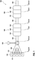
- FIG. 1 an exhaust system 100 for an internal combustion engine 110 is shown schematically, in which a method according to the invention can be carried out.
- the internal combustion engine 110 has, for example, four cylinders 111, which open into an exhaust gas outlet 112 and are connected to a turbocharger 130 via a suitable pipe system 120.
- the turbocharger 130 in turn is connected to a catalytic converter 140 via a suitable pipe system 120.
- the catalytic converter 140 is, for example, divided into three parts or segments 141, 142 and 143.
- a particle filter 150 is connected to the catalytic converter 140 via a suitable pipe system 120.
- the particle filter 150 is, for example, divided into three parts or segments 151, 152 and 153.
- Corresponding temperatures are now shown as examples for various locations or positions in the exhaust system 100, which can be taken into account in a corresponding temperature model.
- the basis of the proposed method is a particularly real-time capable temperature model for the exhaust system, which can be adapted in particular modularly to the respective configuration of the system and the respective components contained therein.
- the catalyst can be divided lengthwise into several parts or segments.
- the average temperature is then calculated for each segment.
- ⁇ T exo denotes an additional contribution to the inlet temperature at the catalyst, which depends, among other things, on the oxygen storage capacity. Since the oxygen storage capacity of a new catalyst is greatest and continues to decrease with age, ⁇ T exo will also continue to decrease.
- the temperatures for the second catalytic converter or particle filter can be calculated in the same way as for the first particle filter.
- the forward model is numerically inverted, i.e. iteratively calculated with different input variables until the value of the output variable, in this case the temperature of the specific component, of the forward model has adjusted to the desired temperature.
- the corresponding settings from this iteration for the input variables for example for the ignition angle efficiency, for the lambda split value and for possibly other variables (such as idle speed, late injection, etc.) are adopted as setpoint values for the internal combustion engine and are therefore used for this purpose that the corresponding temperatures are established in the specific components or a part of them.
- measured values from sensors are also taken into account in the control process R , namely lambda values ⁇ LSU upstream and ⁇ LSF downstream of the catalytic converter and, if necessary, a temperature value T S.
- a model value from the corresponding component can be compared with the sensor value in a step 400, so that a further additive contribution ⁇ T exo,rls can be estimated for the input temperature of the respective component, which is required to reduce the error between the model value and the sensor value in one Minimize step 410.
- a recursive least squares estimator or a Kalman filter can be used.
Landscapes
- Engineering & Computer Science (AREA)
- Chemical & Material Sciences (AREA)
- Chemical Kinetics & Catalysis (AREA)
- Combustion & Propulsion (AREA)
- Mechanical Engineering (AREA)
- General Engineering & Computer Science (AREA)
- Analytical Chemistry (AREA)
- Exhaust Gas After Treatment (AREA)
- Supercharger (AREA)
Description
- Die vorliegende Erfindung betrifft ein Verfahren zum Einstellen einer Temperatur einer Komponente eines Abgassystems, insbesondere eines Kraftfahrzeugs, sowie eine Recheneinheit und ein Computerprogramm zu dessen Durchführung.
- Bei modernen Abgassystemen von bzw. für Brennkraftmaschinen muss die Temperatur jeder einzelnen Komponente in der Regel in einem bestimmten Intervall bzw. Bereich liegen, damit einerseits z.B. bei einem Dreiwegekatalysator eine minimal erforderliche Konvertierungsrate erreicht wird und andererseits bestimmte Komponenten (z.B. eine Turbine eines Turboladers) vor thermischen Schäden geschützt werden. Ebenso muss in der Regel eine bestimmte Temperatur eingestellt werden, um einen Rußabbrand in einem Partikelfilter einzuleiten oder zu stoppen.
- Die
EP 1 067 279 A2 offenbart ein Modell, mit dem die Temperatur eines Katalysators im Abgassystem bestimmt werden kann. Dabei wird basierend auf einer stromaufwärts des Katalysators im Abgas gemessenen Temperatur die Temperatur innerhalb des Katalysators bestimmt, und zwar an zwei verschiedenen Punkten. DieDE 10 2009 051 475 A1 , dieDE 10 2004 033 394 B3 , dieEP 1 761 693 A1 sowie dieEP 1 329 627 A2 beschäftigen sich ebenfalls mit Temperaturen im Abgassystem. - Erfindungsgemäß werden ein Verfahren zum Einstellen einer Temperatur einer Komponente eines Abgassystems sowie eine Recheneinheit und ein Computerprogramm zu dessen Durchführung mit den Merkmalen der unabhängigen Patentansprüche vorgeschlagen. Vorteilhafte Ausgestaltungen sind Gegenstand der Unteransprüche sowie der nachfolgenden Beschreibung.
- Die Erfindung betrifft ein Verfahren zum Einstellen einer Temperatur einer Komponente (oder ggf. eines Teils davon) eines an einen Abgasauslass einer Brennkraftmaschine angebundenen bzw. sich daran anschließenden Abgassystems, insbesondere eines Kraftfahrzeugs. Typische Komponenten in einem solchen Abgassystem sind ein Turbolader, ein Katalysator und ein Partikelfilter. Diese einzelnen Komponenten sind dabei in der Regel über entsprechende Rohrleitungen oder ähnlichem miteinander verbunden.
- Problematisch ist hier bislang, dass es in vielen Abgassystemen nur wenige oder gar keine Temperatursensoren gibt, die man zur Überwachung von komponentenspezifischen Temperaturbereichen einsetzen könnte. Stattdessen ist es üblich, alle relevanten momentanen Temperaturen im Abgassystem in einer ausführenden Recheneinheit bzw. in einem Steuergerät mit einem echtzeitfähigen Modell ausgehend von der üblichen Sensorik im Luftsystem zu berechnen. Aufgrund der hohen Varianz an Abgassystemen muss dieses Modell aber mit entsprechend hohem Applikationsaufwand an die jeweilige Systemkonfiguration (z.B. mehrere Katalysatoren und Partikelfilter an unterschiedlichen Positionen im Fahrzeug) angepasst werden.
- Im Fall eines Ottomotors als Brennkraftmaschine wird das Abgassystem in der Regel aufgeheizt, indem der Zündwinkelwirkungsgrad bewusst verschlechtert wird. Dadurch entsteht Wärme, die stromabwärts das Abgassystem entsprechend aufheizt. Neben dem Zündwinkelwirkungsgrad können aber auch noch weitere Stellgrößen wie z.B. der sog. Lambda-Split-Wert, eine Anhebung der Leerlaufdrehzahl, Späteinspritzung und dergleichen verwendet werden, um das Abgassystem gezielt weiter und schneller aufzuheizen.
- Hierzu werden in der Regel quasistationäre Vorsteuerungen verwendet, die zahlreiche Kennfelder enthalten und über die in Abhängigkeit von weiteren Parametern (beispielsweise eine Füllung der Zylinder und dergleichen) in bestimmten Situationen (z.B. nach dem Motorstart) direkt bestimmte Werte für den Zündwinkelwirkungsgrad und die weiteren Stellgrößen vorgegeben werden. Allerdings ist es damit schwierig, gezielt eine bestimmte Temperatur in einer bestimmten Komponente im Abgassystem einzustellen.
- Oft gelingt es jedoch nur, die Temperatur so stark zu erhöhen, dass ein bestimmter Minimalwert auf jeden Fall innerhalb einer vorgegebenen Zeitspanne überschritten wird. Dabei besteht jedoch die Gefahr, dass die maximal zulässige Temperatur in dieser Komponente oder in einer anderen Komponente ebenfalls überschritten werden kann. Um diese Verletzung der zulässigen Maximaltemperatur zu verhindern, gibt es in den heutigen Motorsteuergeräten entsprechende Maßnahmen zum Bauteileschutz, die den Zündwinkelwirkungsgrad und die weiteren Stellgrößen entsprechend begrenzen. Da diese Schutzfunktionen unabhängig von den Heizmaßnahmen implementiert sind, müssen diese Schutzfunktionen ebenfalls gesondert appliziert werden.
- Bei dem vorgeschlagenen Verfahren wird nun unter Verwendung eines Temperaturmodells des Abgassystems, in dem wenigstens eine Komponente des Abgassystems abgebildet ist, ausgehend von verschiedenen Werten für wenigstens eine, eine Temperatur des Abgassystems beeinflussende Eingangsgröße solange - insbesondere in einem iterativen Verfahren - jeweils eine Temperatur einer bestimmten, in dem Temperaturmodell abgebildeten Komponente des Abgassystems oder eines Teils der Komponente ermittelt, bis ein Wert der Temperatur innerhalb eines vorgegebenen Bereichs liegt bzw. einen vorgegebenen Wert innerhalb bestimmter Toleranzen erreicht hat. Die wenigstens eine Eingangsgröße wird daraufhin auf den zuletzt verwendeten Wert eingestellt. Im Falle mehrerer Eingangsgrößen wird dann für jede Eingangsgröße der jeweils zuletzt, d.h. bei der letzten Iteration, verwendete Wert eingestellt. Denkbar ist auch, für mehrere bestimmte Komponenten oder Teile davon eine entsprechende Temperatur zu ermitteln.
- Die wenigstens eine Eingangsgröße umfasst dabei insbesondere einen Zündwinkelwirkungsgrad der Brennkraftmaschine (insbesondere für den Fall eines Ottomotors) und/oder einen Lambda-Split-Wert und/oder einen Abgasmassenstrom und/oder eine Ansteuergröße eines elektrisch zumindest unterstützend antreibbaren Turboladers. Unter einem Lambda-Split-Verfahren ist dabei zu verstehen, dass unterschiedliche Zylinder der Brennkraftmaschine mit einem unterschiedlichen Lambda-Wert betrieben werden. Entsprechend kann über einen Lambda-Split-Wert eine gewünschte Einstellung der Lambda-Werte in den verschiedenen Zylinder erfolgen.
- Die wenigstens eine Komponente des Abgassystems, die in dem Temperaturmodell abgebildet ist, und von welcher insbesondere auch die Temperatur ermittelt wird, weist insbesondere einen Turbolader auf. Bevorzugt ist auch, wenn die wenigstens eine Komponente des Abgassystems, die in dem Temperaturmodell abgebildet ist, einen Katalysator und/oder einen Partikelfilter aufweist. Diese Komponenten können, wie später noch näher erläutert wird, jeweils wenigstens zwei, insbesondere drei Teile bzw. Segmente aufweisen bzw. in solche eingeteilt sein, die separat in dem Temperaturmodell berücksichtigt sind, wobei dann insbesondere von einem der wenigstens zwei Teile des Katalysators und/oder des Partikelfilters die Temperatur ermittelt wird.
- Die Erfindung macht sich dabei zunutze, dass mit einem solchen Temperaturmodell nicht nur aus einem bestimmten Wert einer Eingangsgröße ein Wert einer Ausgangsgröße, also eine Temperatur einer Komponente des Abgassystems, berechnet werden kann, sondern dass die Berechnungsrichtung auch - zumindest in etwa, im Sinne einer numerischen Invertierung - umgekehrt werden kann, indem für verschiedene Werte der Eingangsgröße solange ein Wert der Ausgangsgröße ermittelt wird, bis dieser einem gewünschten Wert entspricht. Damit ist es also möglich, für eine bestimmte Temperatur einer Komponente im Abgassystem auch ohne Temperatursensor einen möglichst genauen Wert - sozusagen einen Sollwert - zu erhalten und dann einzustellen.
- Ebenso kann dafür gesorgt werden, dass die Temperatur an einer anderen Komponente im Abgassystem vorgegebene Schranken bzw. Temperaturgrenze nicht unter- oder überschreitet. Hierzu wird, wenn die Temperatur der bestimmten, in dem Temperaturmodell abgebildeten Komponente des Abgassystems oder eines Teils der Komponente ermittelt wird, bis der Wert der Temperatur innerhalb des vorgegebenen Bereichs liegt, eine Temperaturgrenze einer anderen, in dem Temperaturmodell abgebildeten Komponente (ggf. aber auch von mehreren Komponenten) des Abgassystems berücksichtigt.
- Auch können Informationen aus der verfügbaren Sensorik des Abgassystems, z.B. Lambdasonden und Temperatursensoren, falls vorhanden, berücksichtigt werden, um ggf. das Modell anzupassen.
- Mit dem vorgeschlagenen Verfahren kann also die Temperatur an einer bestimmten Komponente im Abgassystem (z.B. im Dreiwegekatalysator oder im Partikelfilter) auf einen bestimmten Sollwert eingestellt werden. Während die Temperatur an einer bestimmten Komponente im Abgassystem (z.B. im Dreiwegekatalysator oder im Partikelfilter) auf einen bestimmten Sollwert eingestellt wird, kann gleichzeitig dafür gesorgt werden, dass die obere Schranke für die Temperatur einer anderen Komponente (z.B. Temperatur der Turbine des Turboladers) nicht überschritten wird.
- Während die Temperatur an einer bestimmten Komponente im Abgassystem (z.B. im Partikelfilter) auf einen bestimmten Sollwert eingestellt wird, kann ebenso dafür gesorgt werden, dass die untere Schranke für die Temperatur einer anderen Komponente (z.B. Dreiwegekatalysator) nicht unterschritten wird. Wird die Temperatur im Dreiwegekatalysator innerhalb vorgegebener Schranken gehalten, so kann der Katalysator seine maximale Konvertierungsrate erreichen.
- Wird die Temperatur im Partikelfilter erhöht bzw. erniedrigt, so kann gezielt ein Rußabbrand eingeleitet oder gestoppt werden. Damit ist es möglich, die Rußschicht im Partikelfilter gezielt so einzustellen, dass ein Optimum zwischen Filtrationseffizienz und Abgasgegendruck erzielt werden kann.
- Eine erfindungsgemäße Recheneinheit, z.B. ein Steuergerät eines Kraftfahrzeugs, ist, insbesondere programmtechnisch, dazu eingerichtet, ein erfindungsgemäßes Verfahren durchzuführen.
- Auch die Implementierung eines erfindungsgemäßen Verfahrens in Form eines Computerprogramms oder Computerprogrammprodukts mit Programmcode zur Durchführung aller Verfahrensschritte ist vorteilhaft, da dies besonders geringe Kosten verursacht, insbesondere wenn ein ausführendes Steuergerät noch für weitere Aufgaben genutzt wird und daher ohnehin vorhanden ist. Geeignete Datenträger zur Bereitstellung des Computerprogramms sind insbesondere magnetische, optische und elektrische Speicher, wie z.B. Festplatten, Flash-Speicher, EEPROMs, DVDs u.a.m. Auch ein Download eines Programms über Computernetze (Internet, Intranet usw.) ist möglich.
- Weitere Vorteile und Ausgestaltungen der Erfindung ergeben sich aus der Beschreibung und der beiliegenden Zeichnung.
- Die Erfindung ist anhand eines Ausführungsbeispiels in der Zeichnung schematisch dargestellt und wird im Folgenden unter Bezugnahme auf die Zeichnung beschrieben.
- Kurze Beschreibung der Zeichnungen
- Figur 1
- zeigt schematisch ein Abgassystem für eine Brennkraftmaschine, bei dem ein erfindungsgemäßes Verfahren durchführbar ist.
- Figuren 2
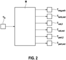
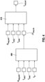
- bis 4 zeigen schematisch Teile eines Ablaufs eines erfindungsgemäßen Verfahrens in einer bevorzugten Ausführungsform.
- In
Figur 1 ist schematisch ein Abgassystem 100 für eine Brennkraftmaschine 110 gezeigt, bei dem ein erfindungsgemäßes Verfahren durchführbar ist. Die Brennkraftmaschine 110 weist beispielhaft vier Zylinder 111 auf, die in einen Abgasauslass 112 münden und über ein geeignetes Rohrsystem 120 an einen Turbolader 130 angebunden sind. - Der Turbolader 130 wiederum ist über ein geeignetes Rohrsystem 120 mit einem Katalysator 140 verbunden. Der Katalysator 140 ist beispielhaft in drei Teile bzw. Segmente 141, 142 und 143 geteilt. Weiterhin schließt sich an den Katalysator 140 über ein geeignetes Rohrsystem 120 ein Partikelfilter 150 an. Der Partikelfilter 150 ist beispielhaft in drei Teile bzw. Segmente 151, 152 und 153 geteilt.
- Für verschiedene Stellen bzw. Positionen im Abgassystem 100 sind nun beispielhaft entsprechende Temperaturen gezeigt, die in einem entsprechenden Temperaturmodell berücksichtigt werden können.
- Grundlage des vorgeschlagenen Verfahrens ist ein insbesondere echtzeitfähiges Temperaturmodell für das Abgassystem, das insbesondere modular auf die jeweilige Konfiguration des Systems und die jeweiligen darin enthaltenen Komponenten angepasst werden kann. Bei der Auslasstemperatur Teng,exh der Brennkraftmaschine nimmt man dazu an, dass diese Temperatur direkt vom Zündwinkelwirkungsgrad ηinj, dem Lambda-Split-Wert ηλ und vom Abgasmassenstrom ṁexh abhängt, ggf. aber auch noch von weiteren Stellgrößen wie z.B. Leerlaufdrehzahl oder Parameter für Späteinspritzung, die zur Vereinfachung aber hier nicht aufgeführt werden:

- Ist die Motorauslasstemperatur bekannt, so kann die Eintrittstemperatur der ersten Komponente (z.B. ein Turbolader mit Tturb,in) im Abgassystem über ein Rohrtemperaturmodell berechnet werden, das im Wesentlichen von der Motorauslasstemperatur Teng,exh, der Umgebungstemperatur Tamb und dem Abgasmassenstrom ṁexh abhängt:

- Bei der Berechnung der Turbinenaustrittstemperatur bzw. der Austrittstemperatur des Turboladers Tturb,out nimmt man an, dass diese Temperatur von der Turbineneintrittstemperatur Tturb,in und dem Druckverhältnis πturb über den Turbolader bzw. dessen Turbine abhängt:

- Der Katalysator lässt sich je nach Aufbau der Länge nach in mehrere Teile bzw. Segmente unterteilen. Für jedes Segment wird dann die mittlere Temperatur berechnet. Für das in
Figur 1 gezeigte Beispiel aus drei Segmenten berechnen sich die mittleren Temperaturen Tcat,1, Tcat,2 und Tcat,out im vorderen, im mittleren und im hinteren Segment wie folgt:


- Hierbei bezeichnet ΔTexo einen zusätzlichen Beitrag für die Eingangstemperatur am Katalysator, der unter anderem von der Sauerstoffspeicherfähigkeit abhängt. Da bei einem neuen Katalysator die Sauerstoffspeicherfähigkeit am größten ist und mit zunehmendem Alter immer weiter abnimmt, wird auch ΔTexo immer weiter abnehmen.
- Ist die Temperatur im hinteren Segment des Katalysators bekannt, so lässt sich über ein weiteres Rohrtemperaturmodell auch die Eingangstemperatur für einen weiteren Katalysator oder, wie im gezeigten Beispiel, einen Partikelfilter berechnen:

- Die Temperaturen für den zweiten Katalysator oder Partikelfilter lassen sich analog wie beim ersten Partikelfilter berechnen. Hierzu wird diese Komponente auch wieder der Länge nach in mehrere Segmente unterteilt (z.B. drei Segmente):


- Auf diese Weise ergibt sich somit ein Temperaturmodell M mit beispielhaft der Eingangsgröße des Zündwinkelwirkungsgrads ηz und den in
Figur 1 gezeigten und vorstehend erläuterten Ausgangsgrößen, wie inFigur 2 schematisch gezeigt. - Natürlich ist es auch möglich, dass auf die oben beschriebene Art und Weise ein Temperaturmodell für komplexere Abgassysteme mit noch mehr Komponenten aufgebaut wird. Die prinzipielle Herangehensweise zur Modellierung bleibt davon unberührt.
- Liegt nun ein Vorwärtsmodell wie in
Figur 2 gezeigt vor, mit dem die mittleren Temperaturen in den einzelnen Komponenten des Abgassystems bestimmt werden können, so lässt sich über ein entsprechendes inverses Modell die benötigte Temperatur in einer bestimmten Komponente des Abgassystems einstellen. - Hierzu wird das Vorwärtsmodell numerisch invertiert, d.h. so oft mit unterschiedlichen Eingangsgrößen iterativ berechnet, bis sich der Wert der Ausgangsgröße, also hier der Temperatur der bestimmten Komponente, des Vorwärtsmodells auf die gewünschte Temperatur eingestellt hat. Die entsprechenden Einstellungen aus dieser Iteration für die Eingangsgrößen, also beispielsweise für den Zündwinkelwirkungsgrad, für den Lambda-Split-Wert und für ggf. weitere Größen (wie z.B. Leerlaufdrehzahl, Späteinspritzung etc.) werden entsprechend für die Brennkraftmaschine als Sollwerte übernommen und damit dazu verwendet, dass sich in der bestimmten Komponenten bzw. einem Teil davon die entsprechenden Temperaturen einstellen.
- Dies ist in
Figur 3 schematisch für die vorstehende Erläuterung mit dem Zündwinkelwirkungsgrad ηz als Eingangsgröße des Temperaturmodells M veranschaulicht, wobei der Zündwinkelwirkungsgrad ηz wiederum eine Stellgröße im Rahmen eines Regelvorgangs R ist, wie er in einer ausführenden Recheneinheit 190 durchgeführt wird. - Dabei werden im Regelvorgang R neben einem Sollwert Tcat,out,SP am Ausgangs des Katalysators und zugehörigem unterem Grenzwert Tcat,out,LL sowie einem oberem Grenzwert Tturb,out,UL für den Ausgang des Turboladers ggf. auch Messwerte von Sensoren berücksichtigt, nämlich Lambda-Werte λLSU stromaufwärts und λLSF stromabwärts des Katalysators sowie ggf. ein Temperaturwert TS.
- Dies zeigt, dass in einer bevorzugten Ausführungsform dieses sog. inversen Temperaturmodells neben dem Sollwert für die Temperatur einer bestimmten Komponente auch noch weitere Randbedingungen (z.B. untere oder obere Schranken) für die Temperatur an einer oder mehreren anderen Komponenten mitberücksichtigt werden können. Damit können relevante Temperaturgrenzen zum Komponentenschutz explizit in dieser Funktion mitberücksichtigt werden.
- Ebenso kann auch dafür gesorgt werden, dass ein Katalysator nicht zu stark auskühlt, wenn am Partikelfilter die Temperatur verringert werden soll. Die iterative Suche nach einer entsprechenden Ansteuerung für den elektrisch unterstützten Turbolader würde prinzipiell genauso ablaufen wie oben beschrieben.
- Stehen zusätzliche Sensoren im Abgassystem zur Verfügung (z.B. Temperatursensor am Ausgang des Katalysators), so kann man diese Information dazu nutzen, das Abgasmodell entsprechend nachzuführen.
- Hierzu kann, wie in
Figur 4 gezeigt, ein Modellwert aus der entsprechenden Komponente in einem Schritt 400 mit dem Sensorwert verglichen werden, sodass ein weitere additiver Beitrag ΔTexo,rls für die Eingangstemperatur der jeweiligen Komponente abgeschätzt werden kann, die erforderlich ist, um den Fehler zwischen Modellwert und Sensorwert in einem Schritt 410 zu minimieren. Hierzu kann z.B. ein rekursiver Least-Squares-Schätzer oder ein Kalmanfilter eingesetzt werden.
Claims (11)
- Verfahren zum Einstellen einer Temperatur (Tcat,out) einer Komponente (130, 140, 150) eines an einen Abgasauslass (112) einer Brennkraftmaschine (110) angebundenen Abgassystems (100),
dadurch gekennzeichnet, dassunter Verwendung eines Temperaturmodells (M) des Abgassystems, in dem wenigstens eine Komponente (130, 140, 150) des Abgassystems abgebildet ist, für verschiedene Werte für wenigstens eine, eine Temperatur des Abgassystems beeinflussende Eingangsgröße (ηz, ṁeng,exh) solange jeweils eine Temperatur einer bestimmten, in dem Temperaturmodell (M) abgebildeten Komponente (130, 140, 150) des Abgassystems oder eines Teils (141, 142, 143, 151, 152, 153) der Komponente ermittelt wird, bis ein Wert der Temperatur (Tcat,out) innerhalb eines vorgegebenen Bereichs liegt, undwobei daraufhin die wenigstens eine Eingangsgröße (ηz, ṁeng,exh) auf den zuletzt verwendeten Wert eingestellt wird. - Verfahren nach Anspruch 1, wobei die wenigstens eine Eingangsgröße einen Zündwinkelwirkungsgrad (ηz) der Brennkraftmaschine und/oder einen Lambda-Split-Wert und/oder einen Abgasmassenstrom (ṁeng,exh) und/oder eine Ansteuergröße eines elektrisch zumindest unterstützend antreibbaren Turboladers umfasst.
- Verfahren nach Anspruch 1 oder 2, wobei die wenigstens eine Komponente des Abgassystems, die in dem Temperaturmodell abgebildet ist, und von welcher insbesondere die Temperatur ermittelt wird, einen Turbolader (130) und/oder einen Katalysator (140) und/oder einen Partikelfilter (150) aufweist.
- Verfahren nach einem der vorstehenden Ansprüche, wobei die wenigstens eine Komponente des Abgassystems, die in dem Temperaturmodell abgebildet ist, einen Katalysator (140) und/oder einen Partikelfilter (150) aufweist.
- Verfahren nach Anspruch 4, wobei der Katalysator (140) und/oder der Partikelfilter (150) jeweils wenigstens zwei Teile (141, 142, 143, 151, 152, 153), aufweisen, die separat in dem Temperaturmodell (M) berücksichtigt sind, und wobei insbesondere von einem der wenigstens zwei Teile des Katalysators und/oder des Partikelfilters die Temperatur ermittelt wird.
- Verfahren nach einem der vorstehenden Ansprüche, wobei, wenn die Temperatur der bestimmten, in dem Temperaturmodell (M) abgebildeten Komponente des Abgassystems oder eines Teils der Komponente ermittelt wird, bis der Wert der Temperatur innerhalb des vorgegebenen Bereichs liegt, eine Temperaturgrenze (Tturb,out,UL, Tcat,out,LL) einer anderen, in dem Temperaturmodell abgebildeten Komponente des Abgassystems (100) berücksichtigt wird.
- Verfahren nach einem der vorstehenden Ansprüche, wobei die Temperatur der bestimmten Komponente des Abgassystems (100) in einem iterativen Verfahren ermittelt wird.
- Verfahren nach einem der vorstehenden Ansprüche, wobei das Temperaturmodell (M) mittels wenigstens eines im Abgassystem (100) vorgesehenen Temperatursensors angepasst wird.
- Recheneinheit (190), die dazu eingerichtet ist, alle Verfahrensschritte eines Verfahrens nach einem der vorstehenden Ansprüche durchzuführen.
- Computerprogramm, das eine Recheneinheit (190) dazu veranlasst, alle Verfahrensschritte eines Verfahrens nach einem der Ansprüche 1 bis 8 durchzuführen, wenn es auf der Recheneinheit (190) ausgeführt wird.
- Maschinenlesbares Speichermedium mit einem darauf gespeicherten Computerprogramm nach Anspruch 10.
Applications Claiming Priority (2)
| Application Number | Priority Date | Filing Date | Title |
|---|---|---|---|
| DE102019212824.6A DE102019212824A1 (de) | 2019-08-27 | 2019-08-27 | Verfahren zum Einstellen einer Temperatur einer Komponente eines Abgassystems |
| PCT/EP2020/069711 WO2021037432A1 (de) | 2019-08-27 | 2020-07-13 | Verfahren zum einstellen einer temperatur einer komponente eines abgassystems |
Publications (2)
| Publication Number | Publication Date |
|---|---|
| EP4022178A1 EP4022178A1 (de) | 2022-07-06 |
| EP4022178B1 true EP4022178B1 (de) | 2023-11-15 |
Family
ID=71614889
Family Applications (1)
| Application Number | Title | Priority Date | Filing Date |
|---|---|---|---|
| EP20740292.6A Active EP4022178B1 (de) | 2019-08-27 | 2020-07-13 | Verfahren zum einstellen einer temperatur einer komponente eines abgassystems |
Country Status (3)
| Country | Link |
|---|---|
| EP (1) | EP4022178B1 (de) |
| DE (1) | DE102019212824A1 (de) |
| WO (1) | WO2021037432A1 (de) |
Families Citing this family (1)
| Publication number | Priority date | Publication date | Assignee | Title |
|---|---|---|---|---|
| DE102021211880A1 (de) | 2021-10-21 | 2023-04-27 | Robert Bosch Gesellschaft mit beschränkter Haftung | Verfahren zum Regeln einer Temperatur eines Abgassystems einer Brennkraftma-schine |
Citations (2)
| Publication number | Priority date | Publication date | Assignee | Title |
|---|---|---|---|---|
| EP1067279B1 (de) * | 1999-07-06 | 2004-08-18 | Siemens Aktiengesellschaft | Verfahren zum Erkennen und Aufrechterhalten der Betriebsbereitschaft eines nox-Speicherkatalysators |
| EP1761693B1 (de) * | 2004-06-22 | 2007-12-12 | GM Global Technology Operations, Inc. | Abschätzung der temperatur eines katalysators und anwendungen dafür |
Family Cites Families (4)
| Publication number | Priority date | Publication date | Assignee | Title |
|---|---|---|---|---|
| DE10201465B4 (de) * | 2002-01-16 | 2004-02-19 | Bayerische Motoren Werke Ag | Verfahren und Vorrichtung zum Steuern einer Bauteilschutzfunktion |
| DE102004033394B3 (de) * | 2004-07-09 | 2005-12-22 | Siemens Ag | Verfahren zur Steuerung einer Brennkraftmaschine |
| DE102006059673A1 (de) * | 2006-12-18 | 2008-06-19 | Robert Bosch Gmbh | System und Verfahren zum Bestimmen mindestens eines Betriebswertes in einer Abgasanlage |
| US8855894B2 (en) * | 2008-11-04 | 2014-10-07 | GM Global Technology Operations LLC | Exhaust temperature and pressure modeling systems and methods |
-
2019
- 2019-08-27 DE DE102019212824.6A patent/DE102019212824A1/de not_active Withdrawn
-
2020
- 2020-07-13 WO PCT/EP2020/069711 patent/WO2021037432A1/de not_active Ceased
- 2020-07-13 EP EP20740292.6A patent/EP4022178B1/de active Active
Patent Citations (2)
| Publication number | Priority date | Publication date | Assignee | Title |
|---|---|---|---|---|
| EP1067279B1 (de) * | 1999-07-06 | 2004-08-18 | Siemens Aktiengesellschaft | Verfahren zum Erkennen und Aufrechterhalten der Betriebsbereitschaft eines nox-Speicherkatalysators |
| EP1761693B1 (de) * | 2004-06-22 | 2007-12-12 | GM Global Technology Operations, Inc. | Abschätzung der temperatur eines katalysators und anwendungen dafür |
Also Published As
| Publication number | Publication date |
|---|---|
| DE102019212824A1 (de) | 2021-03-04 |
| WO2021037432A1 (de) | 2021-03-04 |
| EP4022178A1 (de) | 2022-07-06 |
Similar Documents
| Publication | Publication Date | Title |
|---|---|---|
| DE3827402C2 (de) | ||
| EP1203869B1 (de) | Regelungsanordnung und Verfahren zur Unterbrechung der Regeneration eines Partikelfilters eines Dieselmotors | |
| DE10329763B4 (de) | Koordinierte Regelung einer elektronischen Drosselklappe und eines Turboladers mit variabler Geometrie in ladedruckverstärkten und stöchiometrisch betriebenen Ottomotoren | |
| EP3056718B1 (de) | Verfahren und vorrichtung zur anhebung und/oder absenkung einer abgastemperatur einer brennkraftmaschine mit einer in einer abgasleitung angeordneten abgasnachbehandlungseinrichtung | |
| EP3594480B1 (de) | Verfahren zur steuerung eines aufladungssystems | |
| DE60226204T2 (de) | Vorrichtung zur Steuerung der Abgasabgabe eines Motors | |
| EP3656994B1 (de) | Verfahren zur steuerung eines aufladungssystems | |
| EP2100016B1 (de) | Regelverfahren für einen turbolader einer brennkraftmaschine sowie turbolader | |
| DE102015205195A1 (de) | Regel-/Steuervorrichtung | |
| DE102015205194A1 (de) | Regel-/Steuervorrichtung | |
| DE102017202435A1 (de) | Verfahren und Steuergerät zum Steuern des Öffnungszustandes einer Abgasklappe eines Verbrennungsmotors | |
| DE19723639B4 (de) | Automobilaktuatorschnittstelle | |
| DE102005061876A1 (de) | Verfahren und Vorrichtung zur Steuerung eines Abgasnachbehandlungssystems | |
| EP1669574A2 (de) | Verfahren und Vorrichtung zur Kontrolle der Regeneration eines Partikelfilters | |
| DE102019212824A1 (de) | Verfahren zum Einstellen einer Temperatur einer Komponente eines Abgassystems | |
| DE102012006532A1 (de) | Verfahren und Vorrichtung zur Steuerung eines elektrischen Stellantriebes für eine Wastegate-Ventilanordnung eines Abgasturboladers | |
| DE102014210026B4 (de) | Verfahren und Steuerung zum Steuern eines Aufladungssystems für eine Verbrennungskraftmaschine | |
| EP1368561B1 (de) | Verfahren und vorrichtung zur steuerung einer brennkraftmaschine | |
| DE102018104926B4 (de) | Verfahren zum Betrieb und Einrichtung zur Steuerung und/oder Regelung einer Brennkraftmaschine sowie Brennkraftmaschine | |
| DE102020100434A1 (de) | Verfahren zum Betreiben einer Antriebseinrichtung für ein Kraftfahrzeug sowie entsprechende Antriebseinrichtung | |
| DE102011055275B4 (de) | Verfahren zur Regelung der Abgastemperatur einer direkteinspritzenden Brennkraftmaschine | |
| DE10148973A1 (de) | Verfahren und Vorrichtung zum Ermitteln der Einspritzmenge vorzugsweise für direkteinspritzende Dieselmotoren | |
| DE19957200A1 (de) | Verfahren und Vorrichtung zur Regelung eines Drehmomentes von Dieselmotoren | |
| EP3495649B1 (de) | Verfahren zum abgleich einer von einem luftmassensensor eines verbrennungsmotors erfassten messgrösse | |
| EP3530917A1 (de) | Steuerung zum aufheizen von abgasreinigungsvorrichtungen |
Legal Events
| Date | Code | Title | Description |
|---|---|---|---|
| STAA | Information on the status of an ep patent application or granted ep patent |
Free format text: STATUS: UNKNOWN |
|
| STAA | Information on the status of an ep patent application or granted ep patent |
Free format text: STATUS: THE INTERNATIONAL PUBLICATION HAS BEEN MADE |
|
| PUAI | Public reference made under article 153(3) epc to a published international application that has entered the european phase |
Free format text: ORIGINAL CODE: 0009012 |
|
| STAA | Information on the status of an ep patent application or granted ep patent |
Free format text: STATUS: REQUEST FOR EXAMINATION WAS MADE |
|
| 17P | Request for examination filed |
Effective date: 20220328 |
|
| AK | Designated contracting states |
Kind code of ref document: A1 Designated state(s): AL AT BE BG CH CY CZ DE DK EE ES FI FR GB GR HR HU IE IS IT LI LT LU LV MC MK MT NL NO PL PT RO RS SE SI SK SM TR |
|
| DAV | Request for validation of the european patent (deleted) | ||
| DAX | Request for extension of the european patent (deleted) | ||
| GRAP | Despatch of communication of intention to grant a patent |
Free format text: ORIGINAL CODE: EPIDOSNIGR1 |
|
| STAA | Information on the status of an ep patent application or granted ep patent |
Free format text: STATUS: GRANT OF PATENT IS INTENDED |
|
| INTG | Intention to grant announced |
Effective date: 20230525 |
|
| GRAS | Grant fee paid |
Free format text: ORIGINAL CODE: EPIDOSNIGR3 |
|
| GRAA | (expected) grant |
Free format text: ORIGINAL CODE: 0009210 |
|
| STAA | Information on the status of an ep patent application or granted ep patent |
Free format text: STATUS: THE PATENT HAS BEEN GRANTED |
|
| AK | Designated contracting states |
Kind code of ref document: B1 Designated state(s): AL AT BE BG CH CY CZ DE DK EE ES FI FR GB GR HR HU IE IS IT LI LT LU LV MC MK MT NL NO PL PT RO RS SE SI SK SM TR |
|
| REG | Reference to a national code |
Ref country code: CH Ref legal event code: EP Ref country code: GB Ref legal event code: FG4D Free format text: NOT ENGLISH |
|
| REG | Reference to a national code |
Ref country code: DE Ref legal event code: R096 Ref document number: 502020006060 Country of ref document: DE |
|
| REG | Reference to a national code |
Ref country code: IE Ref legal event code: FG4D Free format text: LANGUAGE OF EP DOCUMENT: GERMAN |
|
| REG | Reference to a national code |
Ref country code: LT Ref legal event code: MG9D |
|
| REG | Reference to a national code |
Ref country code: NL Ref legal event code: MP Effective date: 20231115 |
|
| PG25 | Lapsed in a contracting state [announced via postgrant information from national office to epo] |
Ref country code: GR Free format text: LAPSE BECAUSE OF FAILURE TO SUBMIT A TRANSLATION OF THE DESCRIPTION OR TO PAY THE FEE WITHIN THE PRESCRIBED TIME-LIMIT Effective date: 20240216 |
|
| PG25 | Lapsed in a contracting state [announced via postgrant information from national office to epo] |
Ref country code: IS Free format text: LAPSE BECAUSE OF FAILURE TO SUBMIT A TRANSLATION OF THE DESCRIPTION OR TO PAY THE FEE WITHIN THE PRESCRIBED TIME-LIMIT Effective date: 20240315 |
|
| PG25 | Lapsed in a contracting state [announced via postgrant information from national office to epo] |
Ref country code: LT Free format text: LAPSE BECAUSE OF FAILURE TO SUBMIT A TRANSLATION OF THE DESCRIPTION OR TO PAY THE FEE WITHIN THE PRESCRIBED TIME-LIMIT Effective date: 20231115 |
|
| PG25 | Lapsed in a contracting state [announced via postgrant information from national office to epo] |
Ref country code: NL Free format text: LAPSE BECAUSE OF FAILURE TO SUBMIT A TRANSLATION OF THE DESCRIPTION OR TO PAY THE FEE WITHIN THE PRESCRIBED TIME-LIMIT Effective date: 20231115 |
|
| PG25 | Lapsed in a contracting state [announced via postgrant information from national office to epo] |
Ref country code: ES Free format text: LAPSE BECAUSE OF FAILURE TO SUBMIT A TRANSLATION OF THE DESCRIPTION OR TO PAY THE FEE WITHIN THE PRESCRIBED TIME-LIMIT Effective date: 20231115 |
|
| PG25 | Lapsed in a contracting state [announced via postgrant information from national office to epo] |
Ref country code: NL Free format text: LAPSE BECAUSE OF FAILURE TO SUBMIT A TRANSLATION OF THE DESCRIPTION OR TO PAY THE FEE WITHIN THE PRESCRIBED TIME-LIMIT Effective date: 20231115 Ref country code: LT Free format text: LAPSE BECAUSE OF FAILURE TO SUBMIT A TRANSLATION OF THE DESCRIPTION OR TO PAY THE FEE WITHIN THE PRESCRIBED TIME-LIMIT Effective date: 20231115 Ref country code: IS Free format text: LAPSE BECAUSE OF FAILURE TO SUBMIT A TRANSLATION OF THE DESCRIPTION OR TO PAY THE FEE WITHIN THE PRESCRIBED TIME-LIMIT Effective date: 20240315 Ref country code: GR Free format text: LAPSE BECAUSE OF FAILURE TO SUBMIT A TRANSLATION OF THE DESCRIPTION OR TO PAY THE FEE WITHIN THE PRESCRIBED TIME-LIMIT Effective date: 20240216 Ref country code: ES Free format text: LAPSE BECAUSE OF FAILURE TO SUBMIT A TRANSLATION OF THE DESCRIPTION OR TO PAY THE FEE WITHIN THE PRESCRIBED TIME-LIMIT Effective date: 20231115 Ref country code: BG Free format text: LAPSE BECAUSE OF FAILURE TO SUBMIT A TRANSLATION OF THE DESCRIPTION OR TO PAY THE FEE WITHIN THE PRESCRIBED TIME-LIMIT Effective date: 20240215 Ref country code: PT Free format text: LAPSE BECAUSE OF FAILURE TO SUBMIT A TRANSLATION OF THE DESCRIPTION OR TO PAY THE FEE WITHIN THE PRESCRIBED TIME-LIMIT Effective date: 20240315 |
|
| PG25 | Lapsed in a contracting state [announced via postgrant information from national office to epo] |
Ref country code: SE Free format text: LAPSE BECAUSE OF FAILURE TO SUBMIT A TRANSLATION OF THE DESCRIPTION OR TO PAY THE FEE WITHIN THE PRESCRIBED TIME-LIMIT Effective date: 20231115 Ref country code: RS Free format text: LAPSE BECAUSE OF FAILURE TO SUBMIT A TRANSLATION OF THE DESCRIPTION OR TO PAY THE FEE WITHIN THE PRESCRIBED TIME-LIMIT Effective date: 20231115 Ref country code: PL Free format text: LAPSE BECAUSE OF FAILURE TO SUBMIT A TRANSLATION OF THE DESCRIPTION OR TO PAY THE FEE WITHIN THE PRESCRIBED TIME-LIMIT Effective date: 20231115 Ref country code: NO Free format text: LAPSE BECAUSE OF FAILURE TO SUBMIT A TRANSLATION OF THE DESCRIPTION OR TO PAY THE FEE WITHIN THE PRESCRIBED TIME-LIMIT Effective date: 20240215 Ref country code: LV Free format text: LAPSE BECAUSE OF FAILURE TO SUBMIT A TRANSLATION OF THE DESCRIPTION OR TO PAY THE FEE WITHIN THE PRESCRIBED TIME-LIMIT Effective date: 20231115 Ref country code: HR Free format text: LAPSE BECAUSE OF FAILURE TO SUBMIT A TRANSLATION OF THE DESCRIPTION OR TO PAY THE FEE WITHIN THE PRESCRIBED TIME-LIMIT Effective date: 20231115 |
|
| PG25 | Lapsed in a contracting state [announced via postgrant information from national office to epo] |
Ref country code: DK Free format text: LAPSE BECAUSE OF FAILURE TO SUBMIT A TRANSLATION OF THE DESCRIPTION OR TO PAY THE FEE WITHIN THE PRESCRIBED TIME-LIMIT Effective date: 20231115 |
|
| PG25 | Lapsed in a contracting state [announced via postgrant information from national office to epo] |
Ref country code: CZ Free format text: LAPSE BECAUSE OF FAILURE TO SUBMIT A TRANSLATION OF THE DESCRIPTION OR TO PAY THE FEE WITHIN THE PRESCRIBED TIME-LIMIT Effective date: 20231115 |
|
| PG25 | Lapsed in a contracting state [announced via postgrant information from national office to epo] |
Ref country code: SK Free format text: LAPSE BECAUSE OF FAILURE TO SUBMIT A TRANSLATION OF THE DESCRIPTION OR TO PAY THE FEE WITHIN THE PRESCRIBED TIME-LIMIT Effective date: 20231115 |
|
| PG25 | Lapsed in a contracting state [announced via postgrant information from national office to epo] |
Ref country code: SM Free format text: LAPSE BECAUSE OF FAILURE TO SUBMIT A TRANSLATION OF THE DESCRIPTION OR TO PAY THE FEE WITHIN THE PRESCRIBED TIME-LIMIT Effective date: 20231115 Ref country code: SK Free format text: LAPSE BECAUSE OF FAILURE TO SUBMIT A TRANSLATION OF THE DESCRIPTION OR TO PAY THE FEE WITHIN THE PRESCRIBED TIME-LIMIT Effective date: 20231115 Ref country code: RO Free format text: LAPSE BECAUSE OF FAILURE TO SUBMIT A TRANSLATION OF THE DESCRIPTION OR TO PAY THE FEE WITHIN THE PRESCRIBED TIME-LIMIT Effective date: 20231115 Ref country code: IT Free format text: LAPSE BECAUSE OF FAILURE TO SUBMIT A TRANSLATION OF THE DESCRIPTION OR TO PAY THE FEE WITHIN THE PRESCRIBED TIME-LIMIT Effective date: 20231115 Ref country code: EE Free format text: LAPSE BECAUSE OF FAILURE TO SUBMIT A TRANSLATION OF THE DESCRIPTION OR TO PAY THE FEE WITHIN THE PRESCRIBED TIME-LIMIT Effective date: 20231115 Ref country code: DK Free format text: LAPSE BECAUSE OF FAILURE TO SUBMIT A TRANSLATION OF THE DESCRIPTION OR TO PAY THE FEE WITHIN THE PRESCRIBED TIME-LIMIT Effective date: 20231115 Ref country code: CZ Free format text: LAPSE BECAUSE OF FAILURE TO SUBMIT A TRANSLATION OF THE DESCRIPTION OR TO PAY THE FEE WITHIN THE PRESCRIBED TIME-LIMIT Effective date: 20231115 |
|
| REG | Reference to a national code |
Ref country code: DE Ref legal event code: R097 Ref document number: 502020006060 Country of ref document: DE |
|
| PLBE | No opposition filed within time limit |
Free format text: ORIGINAL CODE: 0009261 |
|
| STAA | Information on the status of an ep patent application or granted ep patent |
Free format text: STATUS: NO OPPOSITION FILED WITHIN TIME LIMIT |
|
| 26N | No opposition filed |
Effective date: 20240819 |
|
| PG25 | Lapsed in a contracting state [announced via postgrant information from national office to epo] |
Ref country code: SI Free format text: LAPSE BECAUSE OF FAILURE TO SUBMIT A TRANSLATION OF THE DESCRIPTION OR TO PAY THE FEE WITHIN THE PRESCRIBED TIME-LIMIT Effective date: 20231115 |
|
| PG25 | Lapsed in a contracting state [announced via postgrant information from national office to epo] |
Ref country code: SI Free format text: LAPSE BECAUSE OF FAILURE TO SUBMIT A TRANSLATION OF THE DESCRIPTION OR TO PAY THE FEE WITHIN THE PRESCRIBED TIME-LIMIT Effective date: 20231115 |
|
| REG | Reference to a national code |
Ref country code: DE Ref legal event code: R119 Ref document number: 502020006060 Country of ref document: DE |
|
| PG25 | Lapsed in a contracting state [announced via postgrant information from national office to epo] |
Ref country code: MC Free format text: LAPSE BECAUSE OF FAILURE TO SUBMIT A TRANSLATION OF THE DESCRIPTION OR TO PAY THE FEE WITHIN THE PRESCRIBED TIME-LIMIT Effective date: 20231115 |
|
| REG | Reference to a national code |
Ref country code: CH Ref legal event code: PL |
|
| PG25 | Lapsed in a contracting state [announced via postgrant information from national office to epo] |
Ref country code: LU Free format text: LAPSE BECAUSE OF NON-PAYMENT OF DUE FEES Effective date: 20240713 |
|
| GBPC | Gb: european patent ceased through non-payment of renewal fee |
Effective date: 20240713 |
|
| PG25 | Lapsed in a contracting state [announced via postgrant information from national office to epo] |
Ref country code: LU Free format text: LAPSE BECAUSE OF NON-PAYMENT OF DUE FEES Effective date: 20240713 |
|
| PG25 | Lapsed in a contracting state [announced via postgrant information from national office to epo] |
Ref country code: DE Free format text: LAPSE BECAUSE OF NON-PAYMENT OF DUE FEES Effective date: 20250201 |
|
| PG25 | Lapsed in a contracting state [announced via postgrant information from national office to epo] |
Ref country code: CH Free format text: LAPSE BECAUSE OF NON-PAYMENT OF DUE FEES Effective date: 20240731 Ref country code: BE Free format text: LAPSE BECAUSE OF NON-PAYMENT OF DUE FEES Effective date: 20240731 |
|
| PG25 | Lapsed in a contracting state [announced via postgrant information from national office to epo] |
Ref country code: FR Free format text: LAPSE BECAUSE OF NON-PAYMENT OF DUE FEES Effective date: 20240731 |
|
| PG25 | Lapsed in a contracting state [announced via postgrant information from national office to epo] |
Ref country code: GB Free format text: LAPSE BECAUSE OF NON-PAYMENT OF DUE FEES Effective date: 20240713 |
|
| REG | Reference to a national code |
Ref country code: BE Ref legal event code: MM Effective date: 20240731 |
|
| PG25 | Lapsed in a contracting state [announced via postgrant information from national office to epo] |
Ref country code: IE Free format text: LAPSE BECAUSE OF NON-PAYMENT OF DUE FEES Effective date: 20240713 |
|
| PG25 | Lapsed in a contracting state [announced via postgrant information from national office to epo] |
Ref country code: FI Free format text: LAPSE BECAUSE OF FAILURE TO SUBMIT A TRANSLATION OF THE DESCRIPTION OR TO PAY THE FEE WITHIN THE PRESCRIBED TIME-LIMIT Effective date: 20231115 |
|
| PGFP | Annual fee paid to national office [announced via postgrant information from national office to epo] |
Ref country code: AT Payment date: 20251020 Year of fee payment: 5 |
|
| PG25 | Lapsed in a contracting state [announced via postgrant information from national office to epo] |
Ref country code: CY Free format text: LAPSE BECAUSE OF FAILURE TO SUBMIT A TRANSLATION OF THE DESCRIPTION OR TO PAY THE FEE WITHIN THE PRESCRIBED TIME-LIMIT; INVALID AB INITIO Effective date: 20200713 |
|
| PG25 | Lapsed in a contracting state [announced via postgrant information from national office to epo] |
Ref country code: HU Free format text: LAPSE BECAUSE OF FAILURE TO SUBMIT A TRANSLATION OF THE DESCRIPTION OR TO PAY THE FEE WITHIN THE PRESCRIBED TIME-LIMIT; INVALID AB INITIO Effective date: 20200713 |