EP4022167B1 - Automatisiertes verfahren für gasliftvorgänge - Google Patents
Automatisiertes verfahren für gasliftvorgänge Download PDFInfo
- Publication number
- EP4022167B1 EP4022167B1 EP20822932.8A EP20822932A EP4022167B1 EP 4022167 B1 EP4022167 B1 EP 4022167B1 EP 20822932 A EP20822932 A EP 20822932A EP 4022167 B1 EP4022167 B1 EP 4022167B1
- Authority
- EP
- European Patent Office
- Prior art keywords
- incremental
- gas injection
- injection rate
- period
- well
- Prior art date
- Legal status (The legal status is an assumption and is not a legal conclusion. Google has not performed a legal analysis and makes no representation as to the accuracy of the status listed.)
- Active
Links
Images







Classifications
-
- E—FIXED CONSTRUCTIONS
- E21—EARTH OR ROCK DRILLING; MINING
- E21B—EARTH OR ROCK DRILLING; OBTAINING OIL, GAS, WATER, SOLUBLE OR MELTABLE MATERIALS OR A SLURRY OF MINERALS FROM WELLS
- E21B43/00—Methods or apparatus for obtaining oil, gas, water, soluble or meltable materials or a slurry of minerals from wells
- E21B43/12—Methods or apparatus for controlling the flow of the obtained fluid to or in wells
- E21B43/121—Lifting well fluids
- E21B43/122—Gas lift
-
- E—FIXED CONSTRUCTIONS
- E21—EARTH OR ROCK DRILLING; MINING
- E21B—EARTH OR ROCK DRILLING; OBTAINING OIL, GAS, WATER, SOLUBLE OR MELTABLE MATERIALS OR A SLURRY OF MINERALS FROM WELLS
- E21B21/00—Methods or apparatus for flushing boreholes, e.g. by use of exhaust air from motor
- E21B21/08—Controlling or monitoring pressure or flow of drilling fluid, e.g. automatic filling of boreholes, automatic control of bottom pressure
-
- E—FIXED CONSTRUCTIONS
- E21—EARTH OR ROCK DRILLING; MINING
- E21B—EARTH OR ROCK DRILLING; OBTAINING OIL, GAS, WATER, SOLUBLE OR MELTABLE MATERIALS OR A SLURRY OF MINERALS FROM WELLS
- E21B44/00—Automatic control systems specially adapted for drilling operations, i.e. self-operating systems which function to carry out or modify a drilling operation without intervention of a human operator, e.g. computer-controlled drilling systems; Systems specially adapted for monitoring a plurality of drilling variables or conditions
-
- E—FIXED CONSTRUCTIONS
- E21—EARTH OR ROCK DRILLING; MINING
- E21B—EARTH OR ROCK DRILLING; OBTAINING OIL, GAS, WATER, SOLUBLE OR MELTABLE MATERIALS OR A SLURRY OF MINERALS FROM WELLS
- E21B47/00—Survey of boreholes or wells
- E21B47/06—Measuring temperature or pressure
Definitions
- US 2018/179869 describes causing, by a processing system proximate to the wellbore, injection of the lift gas into the wellbore at a first gas injection rate; obtaining, by the processing system, a first indication of a parameter associated with the wellbore, an arrival of a first fluid at a wellhead associated with the wellbore, or a composition of the first fluid; determining, by the processing system and based on the first indication, at least one of: a second gas injection rate of the intermittent gas lift system, a first period to inject the lift gas with the intermittent gas lift system, or a second period, subsequent to the first period, with no injection of the lift gas by the intermittent gas lift system; and operating, by the processing system, the intermittent gas lift system according to the determination.
- the present disclosure provides a method for controlling a compressor system for gas lift operations.
- the method includes the steps of:
- the described method may include additional incremental periods at greater gas injection rates.
- the step of operating the compressor system for a first incremental period at a first incremental gas rate greater than the initial gas injection rate is replaced by a step that takes place for a first incremental period at a first incremental gas rate that is less than the initial gas injection rate.
- Subsequent incremental periods operate at incremental gas injection rates less than the prior incremental gas injection rates. Additional incremental periods may be added with each additional incremental period at a lower gas injection rate than the prior incremental period.
- the step of operating the compressor system for a first incremental period at a first incremental gas rate greater than the initial gas injection rate is replaced by a step that takes place at a first incremental gas rate that is greater than the initial gas injection rate and subsequent incremental periods take place at incremental gas injection rates that are less than the first incremental gas injection rate. Additional incremental periods may be added with each additional incremental period at a lower gas injection rate than the prior incremental period.
- the step of operating the compressor system for a first incremental period at a first incremental gas rate greater than the initial gas injection rate is replaced by a step that takes place at a first incremental gas rate that is less than the initial gas injection rate.
- Subsequent incremental periods take place at incremental gas injection rates that are greater than the prior incremental gas injection rates. Additional incremental periods may be added with each additional incremental period at a greater gas injection rate than the prior incremental period.
- the described method may additionally include steps for determining the critical rate of injection.
- the Critical Rate mode comprises the steps of:
- the method may include the steps of:
- This disclosure provides improved methods for managing the operations of oil and gas wells operating under gas lift conditions.
- the improvements include enhancements to the compressor system 10 used to inject gas for gas lift operations and new methods for controlling compressor system 10 operation.
- the improved compressor system 10 includes modifications designed to manage the additional stresses imparted by the new methods.
- improved compressor system 10 has been engineered to withstand the stresses induced by operating under random and/or variable conditions.
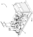
- Compressor system 10 will be described with reference to FIGS. 1-3 .
- Compressor system 10 includes common components such as engine 12, reciprocating compressor 14 and radiator/fan assembly 16. Additionally, compressor system 10 includes a programmable logic controller (PLC), not shown, and a computer server, not shown, suitable for controlling operations of compressor system 10 and managing calculations necessary to carry out the methods disclosed herein.
- PLC programmable logic controller
- the computer server may be located at the wellsite or may be remotely located and accessed as a cloud server or other remote server. Typically, the computer server will perform the necessary calculations and control the operations of the PLC. However, any computer arrangement may be used to perform the operations necessary for carrying out the disclosed methods. For the purposes of conciseness, this disclosure will refer to the various computer control systems and arrangements as a computer server.
- compressor system 10 incorporates pipe supports 18 designed to impart structural rigidity to the supported pipe in every direction. Use of pipe support 18 transfers vibrations and pulses from pipes or conduits to the skid portion of compressor system 10.
- compressor system 10 is particularly suited for carrying out the following methods for automatically and continuously managing gas injection rates thereby improving well production.
- the present invention includes improved methods for controlling compressor system 10.
- the methods disclosed below provide the well operator with the ability to identify and maintain gas injection rates which result in the minimum production pressure.
- the minimum production pressure will be determined either by a bottom hole sensor or a casing pressure sensor located at the surface or any convenient location capable of monitoring pressure at the wellhead.
- the term minimum production pressure refers to that pressure as determined by either a bottom hole pressure sensor, a surface casing pressure sensor or other sensor suitable for determining or calculating the pressure at the bottom of the production casing necessary to lift fluids from the well thereby precluding liquid loading of the well bore.
- the operator When initiating gas lift operation, the operator will typically operate at an injection rate based on the characterization of the well after well completion.
- the initial gas injection rate is calculated based on the gas lift valving configuration, i.e. the type and location of the gas valves, used downhole and the amount of gas needed to unload a full column of liquid to above the first valve depth.
- the first valve is the valve closest to the surface.
- the initial gas injection rate is an estimate. If the initial gas injection rate permits production of the well, then the operator generally continues to use that injection rate. However, over time reservoir and surface conditions will change. In particular, changes in formation pressure, hydrocarbon flow rate into the wellbore and sales line pressure will impact production characteristics. As a result, the initial gas injection rate will not efficiently produce oil from the well for the life of the well.
- the following method provides the ability to continuously adjust operation of compressor system 10 to ensure a gas injection rate which provides the minimum production pressure necessary to lift fluids from the well.
- the disclosed method has two primary components or modes. As used herein, the first primary component is referred to herein as the “Hunt Mode” and the second primary component is referred to herein as the “Critical Rate Mode.”
- the Critical Rate Mode relies upon data developed during performance of the Hunt Mode.
- the Hunt Mode may be used with or without practice of the Critical Rate Mode.
- the Hunt Mode begins with the initial gas injection rate as determined based on factors described above.
- the methods for determining the initial gas injection rate are well known to those skilled in the art.
- the Hunt Mode focuses on determining the minimum gas injection rate corresponding to the minimum production pressure through manipulation and control of compressor system 10.
- FIG. 4 represents the specific gravity ( S g ) of the well fluid mixture produced under varying gas injection rates and the friction resulting from production of wellbore fluids at the varying gas injection rates.
- the low point of the graph, where the gravity and friction lines intersect, will generally represent the minimum gas injection rate suitable for production of oil and other liquids at the minimum production pressure as determined by the available sensors. If the well includes a bottom hole pressure gauge or sensor then the value provided by the sensor is evaluated as the production pressure; however, if a bottom hole pressure gauge is not available, then a pressure gauge or sensor on the surface casing will be used for estimating or determining the production pressure.
- the Hunt Mode provides for incremental alteration of injection rates above and below the initial gas injection rate.
- the method may be repeated after a period to time to readjust the gas injection rate to account for changes in reservoir and/or surface conditions.
- the gas injection rate is manipulated in a stepwise manner in order to identify the gas injection rate necessary for the minimum production pressure to lift wellbore fluids to the surface.
- the system When operating in the Hunt Mode, the system identifies the desired gas injection rate using a range of injection rates.
- the hunt range of injection rates may vary from the prior injection rate by about 5663.4 m 3 /d (200 thousand standard cubic feet per day) (mscfd) to about 28316.8 m 3 /d (1000 mscfd) or up to the capacity of the compressor unit. More typically, the hunt range will vary injection rates from about 14158.4 m 3 /d (500 mscfd) to about 19821.8 m 3 /d (700 mscfd).
- the Hunt Mode will generally increase or decrease the injection rate in a stepwise incremental manner with the number of steps necessary to cover the entire selected range determined by the incremental change in injection rate.
- Each step of incremental change will be held for a defined time period, the incremental period.
- the incremental period will be between about 24 hours and 72 hours. More typically, the incremental period will be about 48 hours.
- production pressure will be monitored. While monitoring of production pressure may take place for the duration of the incremental period, averaging of production pressure does not.
- the well must be allowed to stabilize at that injection rate. Therefore, pressure averaging will take place only after well stabilization.
- pressure data obtained during the first 5% to 15% of the incremental period will be discarded. In other words, the average production pressure is determined over the last 85% to 95% of the incremental period. More typically, pressure data obtained during the first 10% of the incremental period will be discarded.
- the Hunt Mode will follow a predetermined pattern of step-up and step-down injection rates.
- the first increment is a step-up or step-down where the gas injection rate is increased by a defined amount above the initial gas injection rate. If the first incremental period is a step-up, the increase may be between about 707.9 m 3 /d (25 mscfd) to about 2831.7 m 3 /d (100 mscfd).
- a typical increment for the step-up gas injection rate is about 566.3 m 3 /d (20 mscfd) or about 707.9 m 3 /d (25 mscfd).
- the step-up gas injection rate will continue for the incremental period, typically 48 hours.
- the step-up gas injection rate will take place for the incremental period of time at a rate of 17698.0 m 3 /d (625 mscfd).
- production pressure is monitored for an increase in pressure.
- Step-down increments may range from about 283.2 m 3 /d (10 mscfd) to about (100 mscfd).
- a typical increment for the step-down gas injection rate is about 566.3 m 3 /d (20 mscfd) or about 707.9 m 3 /d (25 mscfd).
- the Hunt Mode will require five step-down steps for a hunt range of 17698.0 m 3 /d (625 mscfd) to 14158.4 m 3 /d (500 mscfd) and a step-down increment of 707.9 m 3 /d (25 mscfd).
- the production pressure as determined by either bottom hole pressure or surface casing pressure, will be monitored and averaged as determined by the available sensors.
- data obtained during the initial portion of the incremental period will be discarded.
- a bottom hole pressure sensor is located at the bottom of the vertical portion of the wellbore and a surface casing pressure sensor is located at the surface in a portion of the production tubing.
- the gas injection rate which produced the lowest production pressure is identified as the new Operational Gas Injection Rate, i.e. the solution.
- Compressor system 10 is set at the Operational Gas Injection Rate and allowed to maintain that rate for a defined production period of time.
- the defined production period for continuous operation at the Operational Gas Injection Rate will vary from well to well depending on factors such as effective reservoir size, reservoir pressure, the proximity of adjacent wells and surface conditions such as pressure and flow in the sales line.
- the user will define how long, in their estimation, the solution should be used before repeating the Hunt Mode or utilizing the Critical Rate Mode described below.
- the well operator will also have the option of cutting short the selected period of operation at the solution in response to monitored conditions.
- the above described Hunt Mode can be repeated to determine a new Operational Gas Injection Rate.
- the Hunt Mode for determining the minimum production pressure is not limited to initially operating with a first step-up increment followed by a series of step-down increments. Rather, the method may cover the entire hunt range of gas injection rates by incrementally increasing the gas injection rate from the initial gas injection rate to a desired higher gas injection rate. Likewise, the method may cover the entire hunt range of gas injection rates by incrementally decreasing the gas injection to a final lower gas injection rate. As described above, each incremental step will be for a defined incremental period at a defined incremental change in gas injection rate. Additionally, during each incremental period, the production pressure will be monitored and averaged after allowing the well to stabilize at the incremental gas injection rate.
- the computer server associated with compressor system 10 is programmed on-site or remotely by the well operator with each variable discussed above.
- the computer server may be programmed to manage the methods described herein using conventional programming language.
- One skilled in the art will be familiar with programming code necessary to direct operation of compressor system 10 in accordance with the steps outlined herein.
- Each incremental step is monitored by compressor system 10 and reported by any convenient method, e.g. electronically, to the operator.
- the computer server associated with compressor system 10 calculates the average production pressure using the data obtained during each incremental step and selects the injection rate corresponding to the lowest average production pressure for subsequent continuous operations at the well.
- either the well operator or compressor system 10 repeats the Hunt Mode to readjust the Operational Gas Injection Rate to account for changes in the downhole environment.
- the user or well operator when practicing the Hunt Mode, will provide the initial gas injection rate as determined based on the gas lift valve design or when implemented on a currently producing gas lift system the current injection rate used to achieve production.
- the user will then define the hunt range, the incremental change in gas injection rate and the number of increments to be used during the determination of the minimum production pressure.
- the conditions of the incremental period that produced the minimum production pressure are noted for use in the following Critical Rate Mode.
- the operator will define and input the length of the production period under which the well will operate at the Operational Gas Injection Rate determined by the Hunt Mode to provide the desired minimum production pressure.
- a hunt range Prior to initiating the gas injection management method, the operator determines the hunt range. In this instance, a hunt range of 14158.4 m 3 /d (500 mscfd) to 18122.8 (m 3 /d (640 mscfd) is selected. An initial step-up increment of 1132.7 m 3 /d (40 mscfd) is selected and subsequent step-down increment of 566.3 m 3 /d (20 mscfd) is selected.
- the first increment will provide the initial step-up to 18122.8 m 3 /d (640 mscfd) while seven step-down increments will be required to reach the low end of 14158.4 m 3 /d (500 mscfd).
- the operator determined that the step-up increment will take place over a single 48-hour incremental period.
- the operator determined that each step-down increment occurs over incremental periods of 48 hours.
- the well upon completion of the step-up increment, the well will then operate at a gas injection rate of 17556.4 m 3 /d (620 mscfd) for an incremental period of 48 hours.
- Each subsequent step-down increment will also take place for a defined incremental period of 48 hours.
- the operator has also established the defined production period as the three weeks following determination of the gas injection rate which provides the lowest production pressure.
- compressor system 10 Upon enablement of the Hunt Mode, the computer server associated with compressor system 10 begins by directing the step-up increment.
- compressor system 10 operates at 18122.8 m 3 /d (640 mscfd) for an incremental period of 48 hours and determines an average production pressure over the last 43.2 hours of the step-up incremental period.
- the computer server associated with compressor system 10 directs operations at each step-down incremental period for the defined length of time.
- the gas injection rate is reduced to 17556.4 m 3 /d (620 mscfd).
- Each successive step-down incremental period operates at the defined incremental reduction in gas injection rate of 566.3 m 3 /d (20 mscfd) until the final step-down increment of 14158.4 m 3 /d (500 mscfd).
- the average production pressure will be determined over the last 43.2 hours of each step-down incremental period.
- the computer server associated with compressor system 10 Upon completion of the last incremental period, the computer server associated with compressor system 10 identifies the gas injection rate associated with the lowest average production pressure for a defined incremental period. The identified gas injection rate is designated as the Operational Gas Injection Rate. Then, the computer server associated with compressor system 10 adjusts automatically to continue production of the well at the new Operational Gas Injection Rate. The computer server associated with compressor system 10 will maintain the selected Operational Gas Injection Rate for a period of three weeks as defined by the operator. Upon completion of the three-week or other selected time period, the solution rate can be used to enable the Critical Rate Mode of operation.
- the Hunt Mode provides for repeated adjustment of the Operational Gas Injection Rate to maintain well operation at the injection rate which provides the minimum production pressure.
- the Hunt Mode provides a marked improvement over traditional gas lift operations; however, the Hunt Mode does not provide for continuous real time or even daily adjustment of the gas injection rate. Fortunately, data necessary to continuously update the gas injection rate can be obtained by continuously monitoring the production rate; average production tubing pressure, average production pressure, average sales line pressure. These values and others as discussed below are used in the Critical Rate Mode. While the Hunt Mode can be considered an empirical determination of the desired gas injection rate, the Critical Rate Mode builds on the Hunt Mode empirical solution and provides a continuously updated calculated value of the gas injection rate necessary to produce wellbore fluids to the surface at the minimum production pressure. Thus, the Critical Rate Mode provides continuous fine tuning of the gas injection rate thereby improving production efficiency of the well.
- the Critical Rate Mode utilizes the current gas production rate of the well and adjusts the gas injection rate accordingly to avoid over-injecting and under-injecting the well.
- the Critical Rate Mode operates at the minimum gas injection rate, i.e. the critical rate, necessary to unload the well of all liquids.
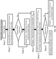
- FIGS. 5A and 5B provide process flow diagrams of the operations carried out by the computer server associated with compressor system 10 to determine the gas injection rate needed to unload fluids from the wellbore at a given production pressure, i.e. the critical rate of gas injection.
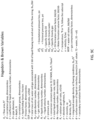
- the computer server can use production pressure data as measured directly by a gauge or sensor or the computer server may calculate the production pressure, as described below, using the Hagedorn and Brown equations of FIGS. 9A-B and a surface casing sensor.
- the units used in either Mode can be adjusted by programming to accommodate the units commonly used by those in the field.
- FIG. 5B incorporates the Vogel IPR parameters produced by FIG. 5A as static values and utilizes real time production pressure data or calculated production pressure data and fluid flow rates out of the formation to adjust the critical rate of gas injection.
- the operations described by the process flow diagrams of FIGS. 5A and 5B are programmed into the computer server associated with compressor system 10.
- the processes of FIGS. 5A and 5B provide the ability to control the operation of compressor system 10 when operating under the
- the process flow diagram of FIG. 5B utilizes the Hagedorn and Brown Equations of FIGS. 9A and 9B to calculate a production pressure based on the measured surface casing pressure and the calculated gravitational pressure loss ⁇ P g (Pa (psi), Equation 1) and calculated frictional pressure loss ⁇ P g (Pa (psi), Equation 2) over the vertical distance of the wellbore.
- the calculated production pressure value is then used in the GUO equation provided at the top of FIG. 6A to calculate the rate of gas injection for use in Step 2 of FIG. 5B .
- the step of using Hagedorn and Brown of FIGS. 9A and 9B can be skipped and the measured production pressure inserted into the GUO equation for use in Step 2 of FIG. 5B .
- the iterative process of FIG. 5A utilizes data obtained from the incremental period of the Hunt Mode which produced the Operational Gas Injection Rate. Additionally, the process of FIG. 5A utilizes operator input relating to the configuration of the well and the configuration of the gas valves installed in the completed well.
- Step 1 of FIG. 5A the operator provides an initial estimate of q max and P .
- a starting point for the initial estimate of P is the normal pressure gradient commonly used to estimate the reservoir pressure and the starting point for the initial estimate of q max (maximum flow rate of fluids through the borehole of the well) is a value equal to double the well's current production rate.
- engineering knowledge of offset wells and data collected from reservoir can be used to establish the initial estimates of P and q max .
- the estimated values are merely the initiation of the process as the method provides an iterative process for establishing the static values of P and q max .
- Step 1 user inputs and other data points will include the following properties relating to the completed wellbore and wellbore operations during the Hunt Mode:
- Step 2 completion of the operations of FIG. 5A requires an iterative determination (Steps 2 and 3) to produce the static Vogel IPR parameters of q max and P corresponding to the gas injection rate that will produce a minimum production pressure within the tolerance range of the Operational Gas Injection Rate identified during the Hunt Mode and the wellbore schematic.
- the acceptable tolerance range for purposes of setting q max and P is that injection rate within about 5% of the Operational Gas Injection Rate that produced the Minimum Production Pressure associated with the Incremental Period.
- Step 1 includes an initial estimate of the values of q max and P .
- the operator or the computer server associated with compressor 10 uses the Hagedorn & Brown equations of FIGS. 9A and 9B to solve for a production pressure. However, if a downhole pressure gauge is used then the production pressure is provided by the direct measurement. Following determination of the production pressure by calculation or direct measurement, Step 2 uses the GUO equations of FIGS. 6A and 6B to solve for the total gas injection rate needed to unload fluids from the well and compares the total gas injection rate to the Operational Gas Injection Rate from the Incremental Period that produced the Minimum Production Pressure. In Step 3, the operator or computer determines if the total gas injection rate is within an acceptable tolerance range when compared to the Operational Gas Injection Rate. If not then they edit q max and P and continue the iterative process until values within the tolerance range are obtained.
- the Hunt Method Operational Gas Injection Rate provides the target value for the GUO solution. If the initial estimates of q max and P produce a gas injection rate value within about 5% of the Operational Gas Injection Rate for the Incremental Period that produce the Operational Gas Injection Rate, i.e. the tolerance range, then the system or user establishes the q max and P as the Vogel static values. If the value of the initially determined gas injection rate produces a GUO solution value outside of the tolerance range, the system or user will perform iterative calculations by changing the initial estimate of q max and P and repeating steps 2-3 until the determined total gas injection rate, when compared to the Operational Gas Injection Rate from the Hunt Mode that produced the Minimum Production Pressure, is within the indicated 5% tolerance range.
- the Vogel static values of q max and P provide the Vogel Curve identified in FIG. 8 .
- the user Upon establishment of the Vogel Curve, the user will then set compressor system 10 to operate in Critical Rate Mode as determined by FIG. 5B .
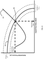
- the graph of FIG. 8 depicts the Hagedorn & Brown model for injection rates at various production pressures and fluid flow rates from the reservoir into the well.
- the intersection of the Hagedorn and Brown outflow model 42 at the gas injection rate with the Vogel IPR Curve 44 identifies the production pressure (bottom hole pressure) needed to calculate the Q gm point 46, i.e.
- FIG. 8 provides a visualization of changes in the Q gm values in response to changes in production pressure ( P wf in FIG. 7 and P hf in FIG. 6A ) and fluid flow rates ( Q o oil flow in m 3 /d (bbl/d), Q g gas flow in m 3 /d (mscfd), Q w water flow in m 3 /d (bbl/d)) during the course of production from the well.
- Step 1 the computer server receives the static values for q max and P from the operator, or from the memory portion of the computer server corresponding to the data use in Step 1 of FIG. 5A . Additionally, Step 1 of FIG. 5B , uses live sensor data directed to fluid flow rates ( Q o oil flow in m 3 /d (bbl/d), Q g gas flow in m 3 /d (mscfd), Q w water flow in m 3 /d (bbl/d)) and data corresponding to monitored production pressure or surface casing pressure suitable for calculating production pressure. Data values may be transmitted directly from the respective sensors to the computer server or may be input manually by the operator.
- the data is entered in real time as an upload from the sensors.
- the frequency of monitoring fluid flow rates and monitoring/calculating production pressure is operator dependent as determined by the nature of the well.
- Compressor system 10 is capable of calculating a new critical rate of gas injection as frequently as the sensors can provide the relevant data.
- the limiting factor in updating the critical rate of gas injection will be the ability of the sensors to transmit data and/or the ability of compressor 10 to respond to the new input provided by the computer associated with compressor system 10.
- Step 2 When operating under the process flow diagram of FIG. 5B , the receipt of new data by the computer associated with compressor system 10 will trigger the operation of Step 2.
- Step 2 if the well has a bottom hole pressure sensor the new bottom hole, the new production pressure value is used directly in Equation 1 of the GUO equations provided in FIG. 6A .
- the monitored values for Q o oil flow in m 3 /d (bbl/d), Q g gas flow in m 3 /d (mscfd), Q w water flow in m 3 /d (bbl/d)) are used in Equation 1 of FIG. 6A .
- Equation 1 is a condensed equation and that equations 2-14 provide for expansion and determination of Q gm .
- These calculations are performed by the computer associated with compressor system 10. Briefly, the operation initially sets Equation 1 to equal zero. Subsequently, in step 3, the value of Q gm is solved iteratively using the Newton-Raphson Method for approximating the root of a function. The computer associated with compressor system 10 will continue the iterative calculation by adjusting the value of Q gm until the final resulting value is within about 28.3 m 3 /d (1 mscfd) to about 141.6 m 3 /d (5 mscfd) of the previous iterated value. Typically, the target variation between the final resulting value of Q gm and the previously iterated value is 141.6 m 3 /d (5 mscfd).
- the process flow diagram of FIG. 5B allows for utilization of a surface casing pressure gauge or sensor in the calculation of the total gas flow rate, Q gm .
- the surface pressure casing sensor provides data to the computer associated with compressor system 10.
- the computer server calculates the production pressure value using the Hagedorn & Brown equations of FIGS. 9A and 9B .
- the production pressure corresponds the surface casing pressure plus the pressure values corresponding to the calculated gravitational pressure loss ⁇ P g (Pa (psi))(Equation 1) and calculated frictional pressure loss ⁇ P g (Pa (psi))(Equation 2) over the vertical distance of the wellbore.
- Step 3 the resulting calculated production pressure is then used in the GUO Equation 1 of FIG. 6A , as discussed above with regard to the measured production pressure, to calculate the total gas flow rate Q gm in m 3 /d (mscfd) necessary to unload liquids from the well.
- Step 3 of FIG. 5B compressor system 10 determines whether or not the iterative process of Step 2 has produced a solution value within 141.6 m 3 /d (5 mscfd) of the prior iterative answer. If this value is also within the tolerance range of about 5.0% then the computer associated with compressor system 10 proceeds to Step 4 and uses the calculated Q gm as the total gas flow required to unload fluids from the well.
- Step 5 the current gas product rate from the well is subtracted from Q gm to provide a final Critical Gas Injection rate.
- the final Critical Gas Injection rate is greater than zero, then the final Critical Gas Injection rate is used to unload the well. If the value is less than zero, the gas lift is not needed to produce fluids.
- Step 3 if the initial calculated Q gm point falls outside of the accepted tolerance range, then the iterative calculation process continues using the Newton-Raphson Method until the Q gm value falls within the predetermined tolerance range for the Q gm value.
- FIG. 8 provides a visual interpretation of the intersection of the solution rate of FIG. 5B with the Vogel IPR parameters.
- the dashed curves show how changing the values of the Vogel IPR parameters of variables q max and P (maximum flow rate and average reservoir pressure) can affect the intersection value of the Hagedorn & Brown production pressure, which is used to find the GUO critical gas injection rate.
- the solid hooked curve labeled Hagedorn-Brown Model depicts how changes in production pressure and fluid production rate influence the gas flow rate needed to produce fluids.
- the point labeled Q gm identifies the critical rate of gas needed to unload liquids from the well at the minimum production pressure. This critical gas rate is provided by GUO solution and then the computer will subtract the measured gas production rate of the well from the GUO critical rate solution to provide the computer instructed gas injection rate used by the compressor.
- compressor system 10 upon identification of the static values for variables q max and P , compressor system 10 initiates calculation of the gas injection rate using the entire flow chart of FIG. 5B .
- Compressor system 10 uses the static IPR values from FIG. 5A in Steps 1-2 to generate a gas injection rate for use in Step 3.
- the calculations performed in Steps 1-2 also use the most recently measured production pressure ( P hf ) and the most recently determined fluid production rate for all fluids produced by the well (q).
- Step 4 provides an output equal to the total gas flow from the bottom of the well necessary to unload the well.
- the computer subtracts the value corresponding to the current net gas produced by the well from the total gas flow of Step 4. If the resulting value is greater than zero, the resulting value is used as the current gas injection rate. If the resulting value is less than zero, then gas injection is not required to unload the fluids from the well.
- compressor system 10 To exemplify the control over the gas injection rate provided by the Critical Rate Mode, we can assume that upon completion of the Hunt Mode, compressor system 10 identified 17556.4 m 3 /d (620 mscfd) as the minimum gas injection rate associated with the defined time period of the Hunt Mode which produced the lowest average production pressure for production of the well. Upon identification of the minimum gas injection rate by the Hunt Mode, compressor system 10 automatically stores this value in its memory or the operator records the value for future reference.
- the variables necessary for the determination of Equations 1-20 in FIGS. 9A-C and Equations 1-14 in FIGS. 6A the variables necessary for the determination of
- the operator Upon completion of the Hunt Mode and storage of the values, the operator will determine variables of q max and P by solving the critical rate equation (Equation 1 of FIG. 6A ) and editing q max and P until solution is within tolerance of the Operational Gas Injection rate provided by the Hunt Mode as described above. If using the generated production pressure value from FIGS. 9A & 9B in Equations 1-14 of FIGS. 6A and 6B generates a gas injection rate within acceptable tolerance 0.0 to 5.0% of the gas injection rate provided by the Hunt Mode, then the selected values of variables q max and P become static values for use in Equations 1-14 of FIGS. 6A and 6B and Equations 1-20 of FIGS. 9A-C in the performance of the flow chart of FIG. 5B .
- compressor system 10 uses the Hagedorn and Brown formulas of FIGS. 9A & 9B to generate a production pressure value ( P wf in FIG. 7 , p hf in FIG. 6A , equation 3) for use in Equations 1-14 of FIGS. 6A and 6B .
- the computer server of compressor system 10 utilizes the static values and measured values directly with a production pressure (bottom hole pressure gauge or indirectly using the surface casing pressure gauge) and fluid production rate ( Q o oil flow in m 3 /d (bbl/d), Q g gas flow in m 3 /d (mscfd), Q w water flow in m 3 /d (bbl/d)) in Steps 1-3 to generate, through an iterative process, a total gas injection rate.
- the computer or PLC subtracts the current gas production rate from the calculated gas injection rate (Step 5) to provide the Critical Gas Rate. If the resulting value is greater than zero, then according to Step 6, the computer or PLC of compressor system 10 directs the compressor to provide the Critical Gas Rate injection value to the downhole portion of the wellbore.
- the Critical Rate Mode provides the most efficient production of fluids from the wellbore as the Critical Rate Mode utilizes the gas injection rate determined by the Hunt Mode while compensating for changes in fluid inflow to the wellbore and changes in downstream gas pressures.
- the compensation allows the Critical Rate Mode to continuously adjust the gas injection rate to ensure that the compressor system 10 efficiently produces all fluids from the well.
Landscapes
- Engineering & Computer Science (AREA)
- Geology (AREA)
- Life Sciences & Earth Sciences (AREA)
- Mining & Mineral Resources (AREA)
- Physics & Mathematics (AREA)
- General Life Sciences & Earth Sciences (AREA)
- Fluid Mechanics (AREA)
- Environmental & Geological Engineering (AREA)
- Geochemistry & Mineralogy (AREA)
- Geophysics (AREA)
- Mechanical Engineering (AREA)
- Control Of Positive-Displacement Pumps (AREA)
- Filling Or Discharging Of Gas Storage Vessels (AREA)
- Fluid-Driven Valves (AREA)
- Control Of Positive-Displacement Air Blowers (AREA)
Claims (15)
- Verfahren zur Steuerung eines Kompressorsystems (10) für den Gasförderbetrieb eines Bohrlochs, umfassend:Betrieb des Kompressorsystems (10) mit einer anfänglichen Gaseinspritzrate, die ausreicht, um sämtliche Flüssigkeiten aus dem Bohrloch zu befördern;Betrieb des Kompressorsystems (10) für einen ersten inkrementellen Zeitraum mit einer ersten inkrementellen Gaseinspritzrate, wobei die erste inkrementelle Gaseinspritzrate entweder größer als die anfängliche Gaseinspritzrate oder kleiner als die anfängliche Gaseinspritzrate ist;Fortsetzung der Förderung von Flüssigkeiten aus dem Bohrloch während des ersten inkrementellen Zeitraums bei gleichzeitiger Überwachung des Förderdrucks innerhalb des Bohrlochs;Bestimmung des durchschnittlichen Förderdrucks während des ersten inkrementellen Zeitraums;wenn die erste inkrementelle Gaseinspritzrate größer ist als die anfängliche Gaseinspritzrate, Betrieb des Kompressorsystems (10) für einen zweiten inkrementellen Zeitraum mit einer zweiten inkrementellen Gaseinspritzrate, wobei die zweite inkrementelle Gaseinspritzrate größer ist als die erste inkrementelle Gaseinspritzrateoder, wenn die erste inkrementelle Gaseinspritzrate geringer ist als die anfängliche Gaseinspritzrate, Betrieb des Kompressorsystems (10) für einen zweiten inkrementellen Zeitraum mit einer zweiten inkrementellen Gaseinspritzrate, wobei die zweite inkrementelle Gaseinspritzrate geringer ist als die erste inkrementelle Gaseinspritzrate;Fortsetzung der Förderung von Flüssigkeiten aus dem Bohrloch während des zweiten inkrementellen Zeitraums bei gleichzeitiger Überwachung des Förderdrucks innerhalb des Bohrlochs;Bestimmung des durchschnittlichen Förderdrucks über den zweiten inkrementellen Zeitraum; wenn die erste inkrementelle Gasinjektionsrate größer ist als die anfängliche Gasinjektionsrate,Betrieb des Kompressorsystems (10) für einen dritten inkrementellen Zeitraum mit einer dritten inkrementellen Gaseinspritzrate, wobei die dritte inkrementelle Gaseinspritzrate größer als die zweite inkrementelle Gaseinspritzrate oder
oder wenn die erste inkrementelle Gaseinspritzrate kleiner ist als die anfängliche Gaseinspritzrate,Betrieb des Kompressorsystems (10) für einen dritten inkrementellen Zeitraum mit einer dritten inkrementellen Gaseinspritzrate, wobei die dritte inkrementelle Gaseinspritzrate kleiner als die zweite inkrementelle Gaseinspritzrate ist;Fortsetzung der Förderung von Flüssigkeiten aus dem Bohrloch während des dritten inkrementellen Zeitraums bei gleichzeitiger Überwachung des Förderdrucks innerhalb des Bohrlochs;Bestimmung des durchschnittlichen Förderdrucks über den dritten inkrementellen Zeitraum;Identifizierung der inkrementellen Gaseinspritzrate, die den niedrigsten durchschnittlichen Förderdruck erzeugte, während kontinuierlich alle Flüssigkeiten aus dem Bohrloch entnommen werden;Einstellen der identifizierten inkrementellen Gaseinspritzrate als operativer Gaseinspritzrate für das Kompressorsystem (10) und Betreiben des Kompressorsystems (10) zur Förderung sämtlicher Flüssigkeiten aus dem Bohrloch; undwobei jeder inkrementelle Zeitraum zwischen etwa 24 Stunden und 72 Stunden dauert. - Das Verfahren nach Anspruch 1 umfasst ferner die folgenden Schritte:wenn die erste inkrementelle Gaseinspritzrate größer ist als die anfängliche Gaseinspritzrate, nach dem dritten inkrementellen Zeitraum Betrieb des Kompressorsystems (10) für einen vierten inkrementellen Zeitraum mit einer vierten inkrementellen Gaseinspritzrate, wobei die vierte inkrementelle Gaseinspritzrate größer ist als die dritte inkrementelle Gaseinspritzrateoder, wenn die erste inkrementelle Gaseinspritzrate geringer ist als die anfängliche Gaseinspritzrate, nach dem dritten inkrementellen Zeitraum Betrieb des Kompressorsystems (10) für einen vierten inkrementellen Zeitraum mit einer vierten inkrementellen Gaseinspritzrate, wobei die vierte inkrementelle Gaseinspritzrate geringer ist als die dritte inkrementelle Gaseinspritzrate;Fortsetzung der Förderung von Flüssigkeiten aus dem Bohrloch während des vierten inkrementellen Zeitraums bei gleichzeitiger Überwachung des Förderdrucks innerhalb des Bohrlochs;Bestimmung des durchschnittlichen Förderdrucks während des vierten inkrementellen Zeitraums.
- Das Verfahren nach Anspruch 1 umfasst ferner die folgenden Schritte:wenn die erste inkrementelle Gaseinspritzrate größer ist als die anfängliche Gaseinspritzrate, nach dem dritten inkrementellen Zeitraum Betrieb des Kompressorsystems (10) für einen vierten inkrementellen Zeitraum mit einer vierten inkrementellen Gaseinspritzrate, wobei die vierte inkrementelle Gaseinspritzrate größer ist als die dritte inkrementelle Gaseinspritzrateoder, wenn die erste inkrementelle Gaseinspritzrate geringer ist als die anfängliche Gaseinspritzrate, nach dem dritten inkrementellen Zeitraum Betrieb des Kompressorsystems (10) für einen vierten inkrementellen Zeitraum mit einer vierten inkrementellen Gaseinspritzrate, wobei die vierte inkrementelle Gaseinspritzrate geringer ist als die dritte inkrementelle Gaseinspritzrate;Fortsetzung der Förderung von Flüssigkeiten aus dem Bohrloch während des vierten inkrementellen Zeitraums bei gleichzeitiger Überwachung des Förderdrucks innerhalb des Bohrlochs;Bestimmung des durchschnittlichen Förderdrucks über den vierten inkrementellen Zeitraum;wenn die erste inkrementelle Gaseinspritzrate größer ist als die anfängliche Gaseinspritzrate und nach dem vierten inkrementellen Zeitraum Betrieb des Kompressorsystems für einen fünften inkrementellen Zeitraum mit einer fünften inkrementellen Gaseinspritzrate, wobei die fünfte inkrementelle Gaseinspritzrate größer ist als die vierte inkrementelle Gaseinspritzrateoder, wenn die erste inkrementelle Gaseinspritzrate geringer ist als die anfängliche Gaseinspritzrate, und nach dem vierten inkrementellen Zeitraum Betrieb des Kompressorsystems (10) für einen fünften inkrementellen Zeitraum mit einer fünften inkrementellen Gaseinspritzrate, wobei die fünfte inkrementelle Gaseinspritzrate geringer ist als die vierte inkrementelle Gaseinspritzrate;Fortsetzung der Förderung von Flüssigkeiten aus dem Bohrloch während des fünften inkrementellen Zeitraums bei gleichzeitiger Überwachung des Förderdrucks innerhalb des Bohrlochs; undBestimmung des durchschnittlichen Förderdrucks während des fünften inkrementellen Zeitraums.
- Das Verfahren nach Anspruch 1 umfasst ferner:wenn die erste inkrementelle Gaseinspritzrate größer ist als die anfängliche Gaseinspritzrate, und nach dem dritten inkrementellen Zeitraum Betrieb des Kompressorsystems (10) für einen vierten inkrementellen Zeitraum mit einer vierten inkrementellen Gaseinspritzrate, wobei die vierte inkrementelle Gaseinspritzrate größer ist als die dritte inkrementelle Gaseinspritzrateoder, wenn die erste inkrementelle Gaseinspritzrate geringer ist als die anfängliche Gaseinspritzrate, und nach dem dritten inkrementellen Zeitraum Betrieb des Kompressorsystems (10) für einen vierten inkrementellen Zeitraum mit einer vierten inkrementellen Gaseinspritzrate, wobei die vierte inkrementelle Gaseinspritzrate geringer ist als die dritte inkrementelle Gaseinspritzrate;Fortsetzung der Förderung von Flüssigkeiten aus dem Bohrloch während des vierten inkrementellen Zeitraums bei gleichzeitiger Überwachung des Förderdrucks innerhalb des Bohrlochs;Bestimmung des durchschnittlichen Förderdrucks über den vierten inkrementellen Zeitraum;wenn die erste inkrementelle Gaseinspritzrate größer ist als die anfängliche Gaseinspritzrate und nach dem vierten inkrementellen Zeitraum Betrieb des Kompressorsystems (10) für einen fünften inkrementellen Zeitraum mit einer fünften inkrementellen Gaseinspritzrate, wobei die fünfte inkrementelle Gaseinspritzrate größer ist als die vierte inkrementelle Gaseinspritzrateoder, wenn die erste inkrementelle Gaseinspritzrate geringer ist als die anfängliche Gaseinspritzrate, und nach dem vierten inkrementellen Zeitraum Betrieb des Kompressorsystems für einen fünften inkrementellen Zeitraum mit einer fünften inkrementellen Gaseinspritzrate, wobei die fünfte inkrementelle Gaseinspritzrate geringer ist als die vierte inkrementelle Gaseinspritzrate;Fortsetzung der Förderung von Flüssigkeiten aus dem Bohrloch während des fünften inkrementellen Zeitraums bei gleichzeitiger Überwachung des Förderdrucks innerhalb des Bohrlochs;Bestimmung des durchschnittlichen Förderdrucks während des fünften inkrementellen Zeitraums;wenn die erste inkrementelle Gaseinspritzrate größer ist als die anfängliche Gaseinspritzrate, und nach dem fünften inkrementellen Zeitraum Betrieb des Kompressorsystems (10) für einen sechsten inkrementellen Zeitraum mit einer sechsten inkrementellen Gaseinspritzrate, wobei die sechste inkrementelle Gaseinspritzrate größer ist als die fünfte inkrementelle Gaseinspritzrateoder, wenn die erste inkrementelle Gaseinspritzrate geringer ist als die anfängliche Gaseinspritzrate, und nach dem fünften inkrementellen Zeitraum Betrieb des Kompressorsystems (10) für einen sechsten inkrementellen Zeitraum mit einer sechsten inkrementellen Gaseinspritzrate, wobei die sechste inkrementelle Gaseinspritzrate geringer ist als die fünfte inkrementelle Gaseinspritzrate;Fortsetzung der Förderung von Flüssigkeiten aus dem Bohrloch während des sechsten inkrementellen Zeitraums bei gleichzeitiger Überwachung des Förderdrucks innerhalb des Bohrlochs; undBestimmung des durchschnittlichen Förderdrucks während des sechsten inkrementellen Zeitraums.
- Verfahren zur Steuerung eines Kompressorsystems (10) für den Gasliftbetrieb eines Bohrlochs, umfassend:Betrieb des Kompressorsystems (10) mit einer anfänglichen Gaseinspritzrate, die ausreicht, um sämtliche Flüssigkeiten aus dem Bohrloch zu heben;Betrieb des Kompressorsystems (10) für einen ersten inkrementellen Zeitraum mit einer ersten inkrementellen Gaseinspritzrate, wobei die erste inkrementelle Gaseinspritzrate entweder größer als die anfängliche Gaseinspritzrate oder kleiner als die anfängliche Gaseinspritzrate ist;Fortsetzung der Förderung von Flüssigkeiten aus dem Bohrloch während des ersten inkrementellen Zeitraums bei gleichzeitiger Überwachung des Förderdrucks innerhalb des Bohrlochs;Bestimmung des durchschnittlichen Förderdrucks während des ersten inkrementellen Zeitraums;wenn die erste inkrementelle Gaseinspritzrate größer ist als die anfängliche Gaseinspritzrate, Betrieb des Kompressorsystems (10) für einen zweiten inkrementellen Zeitraum mit einer zweiten inkrementellen Gaseinspritzrate, wobei die zweite inkrementelle Gaseinspritzrate kleiner ist als die erste inkrementelle Gaseinspritzrateoder, wenn die erste inkrementelle Gaseinspritzrate geringer ist als die anfängliche Gaseinspritzrate, Betrieb des Kompressorsystems (10) für einen zweiten inkrementellen Zeitraum mit einer zweiten inkrementellen Gaseinspritzrate, wobei die zweite inkrementelle Gaseinspritzrate größer ist als die erste inkrementelle Gaseinspritzrate;Fortsetzung der Förderung von Flüssigkeiten aus dem Bohrloch während des zweiten inkrementellen Zeitraums bei gleichzeitiger Überwachung des Förderdrucks innerhalb des Bohrlochs;Bestimmung des durchschnittlichen Förderdrucks über den zweiten inkrementellen Zeitraum;wenn die erste inkrementelle Gaseinspritzrate größer ist als die anfängliche Gaseinspritzrate Betrieb des Kompressorsystems (10) für einen dritten inkrementellen Zeitraum mit einer dritten inkrementellen Gaseinspritzrate, wobei die dritte inkrementelle Gaseinspritzrate größer ist als die zweite inkrementelle Gaseinspritzrateoder, wenn die erste inkrementelle Gaseinspritzrate geringer ist als die anfängliche Gaseinspritzrate, Betrieb des Kompressorsystems (10) für einen dritten inkrementellen Zeitraum mit einer dritten inkrementellen Gaseinspritzrate, wobei die dritte inkrementelle Gaseinspritzrate größer ist als die zweite inkrementelle Gaseinspritzrate;Fortsetzung der Förderung von Flüssigkeiten aus dem Bohrloch während des dritten inkrementellen Zeitraums bei gleichzeitiger Überwachung des Förderdrucks innerhalb des Bohrlochs;Bestimmung des durchschnittlichen Förderdrucks über den dritten inkrementellen Zeitraum;Identifizierung der inkrementellen Gaseinspritzrate, die den niedrigsten durchschnittlichen Förderdruck erzeugte, während kontinuierlich alle Flüssigkeiten aus dem Bohrloch entnommen werden; undEinstellen der identifizierten inkrementellen Gaseinspritzrate als operativer Gaseinspritzrate für das Kompressorsystem (10) und Betreiben des Kompressorsystems (10) zur Förderung sämtlicher Flüssigkeiten aus dem Bohrloch; undwobei jeder inkrementelle Zeitraum zwischen etwa 24 Stunden und 72 Stunden dauert.
- Das Verfahren nach Anspruch 5 umfasst ferner die folgenden Schritte:wenn die erste inkrementelle Gaseinspritzrate größer ist als die anfängliche Gaseinspritzrate, und nach dem dritten inkrementellen Zeitraum Betrieb des Kompressorsystems (10) für einen vierten inkrementellen Zeitraum mit einer vierten inkrementellen Gaseinspritzrate, wobei die vierte inkrementelle Gaseinspritzrate kleiner ist als die dritte inkrementelle Gaseinspritzrateoder, wenn die erste inkrementelle Gaseinspritzrate geringer ist als die anfängliche Gaseinspritzrate, nach dem dritten inkrementellen Zeitraum Betrieb des Kompressorsystems (10) für einen vierten inkrementellen Zeitraum mit einer vierten inkrementellen Gaseinspritzrate, wobei die vierte inkrementelle Gaseinspritzrate größer ist als die dritte inkrementelle Gaseinspritzrate;Fortsetzung der Förderung von Flüssigkeiten aus dem Bohrloch während des vierten inkrementellen Zeitraums bei gleichzeitiger Überwachung des Förderdrucks innerhalb des Bohrlochs; undBestimmung des durchschnittlichen Förderdrucks während des vierten inkrementellen Zeitraums.
- Das Verfahren nach Anspruch 5 umfasst ferner die folgenden Schritte:wenn die erste inkrementelle Gaseinspritzrate größer ist als die anfängliche Gaseinspritzrate, und nach dem dritten inkrementellen Zeitraum Betrieb des Kompressorsystems (10) für einen vierten inkrementellen Zeitraum mit einer vierten inkrementellen Gaseinspritzrate, wobei die vierte inkrementelle Gaseinspritzrate kleiner ist als die dritte inkrementelle Gaseinspritzrateoder, wenn die erste inkrementelle Gaseinspritzrate geringer ist als die anfängliche Gaseinspritzrate, nach dem dritten inkrementellen Zeitraum Betrieb des Kompressorsystems (10) für einen vierten inkrementellen Zeitraum mit einer vierten inkrementellen Gaseinspritzrate, wobei die vierte inkrementelle Gaseinspritzrate größer ist als die dritte inkrementelle Gaseinspritzrate;Fortsetzung der Förderung von Flüssigkeiten aus dem Bohrloch während des vierten inkrementellen Zeitraums bei gleichzeitiger Überwachung des Förderdrucks innerhalb des Bohrlochs;Bestimmung des durchschnittlichen Förderdrucks über den vierten inkrementellen Zeitraum;wenn die erste inkrementelle Gaseinspritzrate größer ist als die anfängliche Gaseinspritzrate und nach dem vierten inkrementellen Zeitraum Betrieb des Kompressorsystems (10) für einen fünften inkrementellen Zeitraum mit einer fünften inkrementellen Gaseinspritzrate, wobei die fünfte inkrementelle Gaseinspritzrate geringer ist als die vierte inkrementelle Gaseinspritzrateoder, wenn die erste inkrementelle Gaseinspritzrate geringer ist als die anfängliche Gaseinspritzrate, und nach dem vierten inkrementellen Zeitraum Betrieb des Kompressorsystems (10) für einen fünften inkrementellen Zeitraum mit einer fünften inkrementellen Gaseinspritzrate, wobei die fünfte inkrementelle Gaseinspritzrate größer ist als die vierte inkrementelle Gaseinspritzrate;Fortsetzung der Förderung von Flüssigkeiten aus dem Bohrloch während des fünften inkrementellen Zeitraums bei gleichzeitiger Überwachung des Förderdrucks innerhalb des Bohrlochs;Bestimmung des durchschnittlichen Förderdrucks während des fünften inkrementellen Zeitraums.
- Das Verfahren nach Anspruch 5 umfasst ferner:wenn die erste inkrementelle Gaseinspritzrate größer ist als die anfängliche Gaseinspritzrate, und nach dem dritten inkrementellen Zeitraum Betrieb des Kompressorsystems (10) für einen vierten inkrementellen Zeitraum mit einer vierten inkrementellen Gaseinspritzrate, wobei die vierte inkrementelle Gaseinspritzrate kleiner ist als die dritte inkrementelle Gaseinspritzrateoder, wenn die erste inkrementelle Gaseinspritzrate geringer ist als die anfängliche Gaseinspritzrate, und nach dem dritten inkrementellen Zeitraum Betrieb des Kompressorsystems (10) für einen vierten inkrementellen Zeitraum mit einer vierten inkrementellen Gaseinspritzrate, wobei die vierte inkrementelle Gaseinspritzrate größer ist als die dritte inkrementelle Gaseinspritzrate;Fortsetzung der Förderung von Flüssigkeiten aus dem Bohrloch während des vierten inkrementellen Zeitraums bei gleichzeitiger Überwachung des Förderdrucks innerhalb des Bohrlochs;Bestimmung des durchschnittlichen Förderdrucks über den vierten inkrementellen Zeitraum;wenn die erste inkrementelle Gaseinspritzrate größer ist als die anfängliche Gaseinspritzrate und nach dem vierten inkrementellen Zeitraum Betrieb des Kompressorsystems (10) für einen fünften inkrementellen Zeitraum mit einer fünften inkrementellen Gaseinspritzrate, wobei die fünfte inkrementelle Gaseinspritzrate geringer ist als die vierte inkrementelle Gaseinspritzrateoder, wenn die erste inkrementelle Gaseinspritzrate geringer ist als die anfängliche Gaseinspritzrate, und nach dem vierten inkrementellen Zeitraum Betrieb des Kompressorsystems (10) für einen fünften inkrementellen Zeitraum mit einer fünften inkrementellen Gaseinspritzrate, wobei die fünfte inkrementelle Gaseinspritzrate größer ist als die vierte inkrementelle Gaseinspritzrate;Fortsetzung der Förderung von Flüssigkeiten aus dem Bohrloch während des fünften inkrementellen Zeitraums bei gleichzeitiger Überwachung des Förderdrucks innerhalb des Bohrlochs;Bestimmung des durchschnittlichen Förderdrucks während des fünften inkrementellen Zeitraums;wenn die erste inkrementelle Gaseinspritzrate größer ist als die anfängliche Gaseinspritzrate, und nach dem fünften inkrementellen Zeitraum Betrieb des Kompressorsystems (10) für einen sechsten inkrementellen Zeitraum mit einer sechsten inkrementellen Gaseinspritzrate, wobei die sechste inkrementelle Gaseinspritzrate geringer ist als die fünfte inkrementelle Gaseinspritzrate;oder, wenn die erste inkrementelle Gaseinspritzrate geringer ist als die anfängliche Gaseinspritzrate, und nach dem fünften inkrementellen Zeitraum Betrieb des Kompressorsystems (10) für einen sechsten inkrementellen Zeitraum mit einer sechsten inkrementellen Gaseinspritzrate, wobei die sechste inkrementelle Gaseinspritzrate größer ist als die fünfte inkrementelle Gaseinspritzrate;Fortsetzung der Förderung von Flüssigkeiten aus dem Bohrloch während des sechsten inkrementellen Zeitraums bei gleichzeitiger Überwachung des Förderdrucks innerhalb des Bohrlochs; undBestimmung des durchschnittlichen Förderdrucks während des sechsten inkrementellen Zeitraums.
- Verfahren nach Anspruch 1 oder 5, wobei die Zunahme oder Abnahme der Gaseinspritzrate während des ersten, zweiten und dritten inkrementellen Zeitraums etwa 566,3 m3/Tag (20 mscfd) bis etwa 2265,3 m3/Tag (80 mscfd) beträgt.
- Verfahren nach Anspruch 1 oder 5, das ferner den Schritt des Aufzeichnens der Bohrlochbedingungen der Flüssigkeitsdurchflussraten, der Gasproduktionsrate und der Gaseinspritzrate umfasst, die den niedrigsten durchschnittlichen Förderdruck während der inkrementellen Zeiträume erzeugten.
- Verfahren nach Anspruch 1 oder 5, wobei der inkrementelle Zeitraum zwischen etwa 36 Stunden und etwa 60 Stunden dauert.
- Das Verfahren nach Anspruch 1 oder 5 umfasst ferner die folgenden Schritte:Schätzung der maximalen Durchflussrate von Flüssigkeiten aus dem Bohrloch (qmax ) und des durchschnittlichen Reservoirdrucks (
P ) bei der maximalen Durchflussrate der Flüssigkeiten aus dem Bohrloch;Messung des Förderdrucks mit einem Sensor am Boden des Bohrlochs oder Messung des Drucks im Oberflächengehäuse mit einem Oberflächensensor und Berechnung des Förderdrucks;Berechnung der gesamten Gaseinspritzrate, die erforderlich ist, um alle Flüssigkeiten aus dem Bohrloch zu befördern, unter Verwendung des gemessenen oder berechneten Förderdrucks und der geschätzten Werte von qmax undP ;Vergleichen der berechneten Gesamtgasinjektionsrate mit der Gasinjektionsrate, die den niedrigsten Förderdruck erzeugte, während alle Flüssigkeiten aus dem Bohrloch entnommen wurden, wenn die berechnete Gesamtgasinjektionsrate innerhalb des Toleranzbereichs der Gasinjektionsrate liegt, die den niedrigsten Förderdruck erzeugte, während alle Flüssigkeiten aus dem Bohrloch entnommen wurden, dann Festlegen der Werte von qmax undP als statische Werte für die Berechnung der minimalen Gasinjektionsrate, die erforderlich ist, um sämtliche Flüssigkeiten aus dem Bohrloch zu befördern;Berechnung der minimalen Gasinjektionsrate, die erforderlich ist, um sämtliche Flüssigkeiten aus dem Bohrloch zu befördern; und Ansteuerung des Kompressorsystems (10), um mit der berechneten minimalen Gasinjektionsrate zu arbeiten. - Verfahren nach Anspruch 12, wobei der Schritt des Berechnens der minimalen Gasinjektionsrate, die erforderlich ist, um sämtliche Flüssigkeiten aus dem Bohrloch zu befördern, ferner die folgenden Schritte umfasst:Überwachung der Durchflussraten von Wasser, Gas und Öl aus dem Bohrloch;Überwachung des Drucks am Boden des Bohrlochs oder Berechnung des Drucks am Boden des Bohrlochs unter Verwendung des überwachten Drucks im Oberflächengehäuse;Berechnung der gesamten Gasdurchflussmenge, die erforderlich ist, um sämtliche Flüssigkeiten aus dem Bohrloch zu befördern;Subtraktion der Gas-Durchflussrate aus dem Bohrloch von der berechneten Gesamtgasdurchflussrate, die erforderlich ist, um alle Flüssigkeiten aus dem Bohrloch zu befördern, um die minimale Gasinjektionsrate zu erhalten, die erforderlich ist, um sämtliche Flüssigkeiten aus dem Bohrloch zu befördern; undBetrieb des Kompressorsystems (10) mit der minimalen Gasinjektionsrate, die erforderlich ist, um sämtliche Flüssigkeiten aus dem Bohrloch zu befördern.
- Verfahren nach Anspruch 13, das ferner den Schritt des Vergleichens der kritischen Gaseinspritzrate mit der Gas-Durchflussrate aus dem Bohrloch und des Beendens des Betriebs des Kompressorsystems (10) umfasst, wenn die kritische Gaseinspritzrate geringer ist als die Gas-Durchflussrate aus dem Bohrloch.
- Verfahren nach Anspruch 1 oder 5, wobei der Schritt des Bestimmens des durchschnittlichen Förderdrucks während des ersten inkrementellen Zeitraums über die letzten 85 % bis 95 % des ersten inkrementellen Zeitraums, wobei der Schritt des Bestimmens des durchschnittlichen Förderdrucks während des zweiten inkrementellen Zeitraums über die letzten 85 % bis 95 % des zweiten inkrementellen Zeitraums, und wobei der Schritt des Bestimmens des durchschnittlichen Förderdrucks während des dritten inkrementellen Zeitraums über die letzten 85 % bis 95 % des dritten inkrementellen Zeitraums erfolgt.
Applications Claiming Priority (2)
| Application Number | Priority Date | Filing Date | Title |
|---|---|---|---|
| US201962893976P | 2019-08-30 | 2019-08-30 | |
| PCT/US2020/047014 WO2020252494A1 (en) | 2019-08-30 | 2020-08-19 | Automated method for gas lift operations |
Publications (3)
| Publication Number | Publication Date |
|---|---|
| EP4022167A1 EP4022167A1 (de) | 2022-07-06 |
| EP4022167A4 EP4022167A4 (de) | 2023-09-13 |
| EP4022167B1 true EP4022167B1 (de) | 2024-11-20 |
Family
ID=73782127
Family Applications (1)
| Application Number | Title | Priority Date | Filing Date |
|---|---|---|---|
| EP20822932.8A Active EP4022167B1 (de) | 2019-08-30 | 2020-08-19 | Automatisiertes verfahren für gasliftvorgänge |
Country Status (11)
| Country | Link |
|---|---|
| US (1) | US11572771B2 (de) |
| EP (1) | EP4022167B1 (de) |
| CN (1) | CN114341461A (de) |
| AU (1) | AU2020292446B2 (de) |
| CA (1) | CA3152889C (de) |
| CO (1) | CO2022001615A2 (de) |
| IL (1) | IL290932B2 (de) |
| MX (1) | MX2022001968A (de) |
| NO (1) | NO347111B1 (de) |
| SA (1) | SA522431790B1 (de) |
| WO (1) | WO2020252494A1 (de) |
Families Citing this family (1)
| Publication number | Priority date | Publication date | Assignee | Title |
|---|---|---|---|---|
| CN112943170B (zh) * | 2021-03-03 | 2022-08-09 | 盘锦华晨石油装备制造有限公司 | 一种低压气井增压增产伴生循环气举系统 |
Family Cites Families (18)
| Publication number | Priority date | Publication date | Assignee | Title |
|---|---|---|---|---|
| US5871048A (en) * | 1997-03-26 | 1999-02-16 | Chevron U.S.A. Inc. | Determining an optimum gas injection rate for a gas-lift well |
| US6595287B2 (en) * | 2000-10-06 | 2003-07-22 | Weatherford/Lamb, Inc. | Auto adjusting well control system and method |
| CN101415905A (zh) * | 2006-04-07 | 2009-04-22 | 国际壳牌研究有限公司 | 优化井组产量的方法 |
| US7784548B2 (en) | 2008-04-23 | 2010-08-31 | Conocophillips Company | Smart compressed chamber well optimization system |
| US8670966B2 (en) * | 2008-08-04 | 2014-03-11 | Schlumberger Technology Corporation | Methods and systems for performing oilfield production operations |
| US7802625B2 (en) | 2008-11-11 | 2010-09-28 | Nitro-Lift Hydrocarbon Recovery Systems, Llc | System and method for producing a well using a gas |
| US8113288B2 (en) * | 2010-01-13 | 2012-02-14 | David Bachtell | System and method for optimizing production in gas-lift wells |
| US20120215364A1 (en) * | 2011-02-18 | 2012-08-23 | David John Rossi | Field lift optimization using distributed intelligence and single-variable slope control |
| SG11201407790SA (en) * | 2012-06-15 | 2014-12-30 | Landmark Graphics Corp | Methods and systems for gas lift rate management |
| US10138724B2 (en) * | 2012-07-31 | 2018-11-27 | Landmark Graphics Corporation | Monitoring, diagnosing and optimizing gas lift operations by presenting one or more actions recommended to achieve a GL system performance |
| US10443358B2 (en) | 2014-08-22 | 2019-10-15 | Schlumberger Technology Corporation | Oilfield-wide production optimization |
| US9951601B2 (en) | 2014-08-22 | 2018-04-24 | Schlumberger Technology Corporation | Distributed real-time processing for gas lift optimization |
| WO2016084054A1 (en) | 2014-11-30 | 2016-06-02 | Abb Technology Ltd. | Method and system for maximizing production of a well with a gas assisted plunger lift |
| US10077642B2 (en) * | 2015-08-19 | 2018-09-18 | Encline Artificial Lift Technologies LLC | Gas compression system for wellbore injection, and method for optimizing gas injection |
| US20170343986A1 (en) * | 2016-05-31 | 2017-11-30 | General Electric Company | Methods and system for enhancing flow of a gas lifted well |
| RU2743526C2 (ru) | 2016-09-26 | 2021-02-19 | Бристоль, Инк., Д/Б/А Ремоут Аутомейшен Солюшенз | Автоматизированная промывочная система для системы винтового насоса |
| US10689958B2 (en) * | 2016-12-22 | 2020-06-23 | Weatherford Technology Holdings, Llc | Apparatus and methods for operating gas lift wells |
| US11649704B2 (en) * | 2018-04-12 | 2023-05-16 | Lift Ip Etc, Llc | Processes and systems for injection of a liquid and gas mixture into a well |
-
2020
- 2020-08-19 MX MX2022001968A patent/MX2022001968A/es unknown
- 2020-08-19 CN CN202080061313.1A patent/CN114341461A/zh active Pending
- 2020-08-19 US US17/636,588 patent/US11572771B2/en active Active
- 2020-08-19 EP EP20822932.8A patent/EP4022167B1/de active Active
- 2020-08-19 WO PCT/US2020/047014 patent/WO2020252494A1/en not_active Ceased
- 2020-08-19 CA CA3152889A patent/CA3152889C/en active Active
- 2020-08-19 AU AU2020292446A patent/AU2020292446B2/en active Active
- 2020-08-19 NO NO20220379A patent/NO347111B1/en unknown
-
2022
- 2022-02-16 CO CONC2022/0001615A patent/CO2022001615A2/es unknown
- 2022-02-27 IL IL290932A patent/IL290932B2/en unknown
- 2022-02-28 SA SA522431790A patent/SA522431790B1/ar unknown
Also Published As
| Publication number | Publication date |
|---|---|
| US11572771B2 (en) | 2023-02-07 |
| IL290932A (en) | 2022-04-01 |
| CA3152889C (en) | 2023-01-24 |
| AU2020292446B2 (en) | 2023-01-05 |
| CN114341461A (zh) | 2022-04-12 |
| EP4022167A4 (de) | 2023-09-13 |
| NO347111B1 (en) | 2023-05-15 |
| NO20220379A1 (en) | 2022-03-29 |
| BR112022002374A2 (pt) | 2022-06-14 |
| EP4022167A1 (de) | 2022-07-06 |
| CA3152889A1 (en) | 2020-12-17 |
| AU2020292446A1 (en) | 2022-03-17 |
| WO2020252494A1 (en) | 2020-12-17 |
| SA522431790B1 (ar) | 2023-12-17 |
| US20220268137A1 (en) | 2022-08-25 |
| CO2022001615A2 (es) | 2022-03-18 |
| IL290932B1 (en) | 2023-01-01 |
| IL290932B2 (en) | 2023-05-01 |
| MX2022001968A (es) | 2022-03-11 |
Similar Documents
| Publication | Publication Date | Title |
|---|---|---|
| US10920546B2 (en) | Apparatus and methods for operating gas lift wells | |
| US7350597B2 (en) | Drilling system and method | |
| CA2443175C (en) | Control system for progressing cavity pumps | |
| CN102402184B (zh) | 井筒压力模型预测系统控制方法 | |
| US10876383B2 (en) | Method and system for maximizing production of a well with a gas assisted plunger lift | |
| US5871048A (en) | Determining an optimum gas injection rate for a gas-lift well | |
| US11555387B2 (en) | Downhole tool movement control system and method of use | |
| EA005470B1 (ru) | Система для регулирования рабочих давлений в подземной буровой скважине | |
| US20190257153A1 (en) | System and method for mitigating torsional vibrations | |
| US12546203B2 (en) | Systems and methods to perform automated drilling | |
| US11649705B2 (en) | Oil and gas well carbon capture system and method | |
| US11746628B2 (en) | Multi-stage downhole tool movement control system and method of use | |
| US11572771B2 (en) | Automated method for gas lift operations | |
| US5819849A (en) | Method and apparatus for controlling pump operations in artificial lift production | |
| US20190353016A1 (en) | Gas lift optimization process | |
| RU2811011C1 (ru) | Автоматизированный способ выполнения газлифтных операций | |
| O'Reilly et al. | Pressure and rate transient analysis of artificially lifted drawdown tests using cyclic Pump Off Controllers | |
| Sajjad et al. | A New Gas Lift Design Pradigm: Moving from Static Based Modeling to Dynamic, Realtime Modeling to Achieve Operational Excellence in Field X |
Legal Events
| Date | Code | Title | Description |
|---|---|---|---|
| STAA | Information on the status of an ep patent application or granted ep patent |
Free format text: STATUS: THE INTERNATIONAL PUBLICATION HAS BEEN MADE |
|
| PUAI | Public reference made under article 153(3) epc to a published international application that has entered the european phase |
Free format text: ORIGINAL CODE: 0009012 |
|
| STAA | Information on the status of an ep patent application or granted ep patent |
Free format text: STATUS: REQUEST FOR EXAMINATION WAS MADE |
|
| 17P | Request for examination filed |
Effective date: 20220203 |
|
| AK | Designated contracting states |
Kind code of ref document: A1 Designated state(s): AL AT BE BG CH CY CZ DE DK EE ES FI FR GB GR HR HU IE IS IT LI LT LU LV MC MK MT NL NO PL PT RO RS SE SI SK SM TR |
|
| DAV | Request for validation of the european patent (deleted) | ||
| DAX | Request for extension of the european patent (deleted) | ||
| A4 | Supplementary search report drawn up and despatched |
Effective date: 20230811 |
|
| RIC1 | Information provided on ipc code assigned before grant |
Ipc: E21B 44/00 20060101ALI20230807BHEP Ipc: E21B 47/06 20120101ALI20230807BHEP Ipc: E21B 47/008 20120101ALI20230807BHEP Ipc: E21B 41/00 20060101ALI20230807BHEP Ipc: E21B 34/02 20060101ALI20230807BHEP Ipc: E21B 21/08 20060101ALI20230807BHEP Ipc: E21B 43/12 20060101AFI20230807BHEP |
|
| GRAP | Despatch of communication of intention to grant a patent |
Free format text: ORIGINAL CODE: EPIDOSNIGR1 |
|
| STAA | Information on the status of an ep patent application or granted ep patent |
Free format text: STATUS: GRANT OF PATENT IS INTENDED |
|
| INTG | Intention to grant announced |
Effective date: 20240612 |
|
| GRAS | Grant fee paid |
Free format text: ORIGINAL CODE: EPIDOSNIGR3 |
|
| GRAA | (expected) grant |
Free format text: ORIGINAL CODE: 0009210 |
|
| STAA | Information on the status of an ep patent application or granted ep patent |
Free format text: STATUS: THE PATENT HAS BEEN GRANTED |
|
| P01 | Opt-out of the competence of the unified patent court (upc) registered |
Free format text: CASE NUMBER: APP_55264/2024 Effective date: 20241008 |
|
| AK | Designated contracting states |
Kind code of ref document: B1 Designated state(s): AL AT BE BG CH CY CZ DE DK EE ES FI FR GB GR HR HU IE IS IT LI LT LU LV MC MK MT NL NO PL PT RO RS SE SI SK SM TR |
|
| REG | Reference to a national code |
Ref country code: GB Ref legal event code: FG4D |
|
| REG | Reference to a national code |
Ref country code: CH Ref legal event code: EP |
|
| REG | Reference to a national code |
Ref country code: DE Ref legal event code: R096 Ref document number: 602020041775 Country of ref document: DE |
|
| REG | Reference to a national code |
Ref country code: IE Ref legal event code: FG4D |
|
| REG | Reference to a national code |
Ref country code: LT Ref legal event code: MG9D |
|
| REG | Reference to a national code |
Ref country code: NL Ref legal event code: MP Effective date: 20241120 |
|
| PG25 | Lapsed in a contracting state [announced via postgrant information from national office to epo] |
Ref country code: PT Free format text: LAPSE BECAUSE OF FAILURE TO SUBMIT A TRANSLATION OF THE DESCRIPTION OR TO PAY THE FEE WITHIN THE PRESCRIBED TIME-LIMIT Effective date: 20250320 Ref country code: HR Free format text: LAPSE BECAUSE OF FAILURE TO SUBMIT A TRANSLATION OF THE DESCRIPTION OR TO PAY THE FEE WITHIN THE PRESCRIBED TIME-LIMIT Effective date: 20241120 Ref country code: IS Free format text: LAPSE BECAUSE OF FAILURE TO SUBMIT A TRANSLATION OF THE DESCRIPTION OR TO PAY THE FEE WITHIN THE PRESCRIBED TIME-LIMIT Effective date: 20250320 |
|
| PG25 | Lapsed in a contracting state [announced via postgrant information from national office to epo] |
Ref country code: NL Free format text: LAPSE BECAUSE OF FAILURE TO SUBMIT A TRANSLATION OF THE DESCRIPTION OR TO PAY THE FEE WITHIN THE PRESCRIBED TIME-LIMIT Effective date: 20241120 Ref country code: FI Free format text: LAPSE BECAUSE OF FAILURE TO SUBMIT A TRANSLATION OF THE DESCRIPTION OR TO PAY THE FEE WITHIN THE PRESCRIBED TIME-LIMIT Effective date: 20241120 |
|
| REG | Reference to a national code |
Ref country code: AT Ref legal event code: MK05 Ref document number: 1743728 Country of ref document: AT Kind code of ref document: T Effective date: 20241120 |
|
| PG25 | Lapsed in a contracting state [announced via postgrant information from national office to epo] |
Ref country code: BG Free format text: LAPSE BECAUSE OF FAILURE TO SUBMIT A TRANSLATION OF THE DESCRIPTION OR TO PAY THE FEE WITHIN THE PRESCRIBED TIME-LIMIT Effective date: 20241120 |
|
| PG25 | Lapsed in a contracting state [announced via postgrant information from national office to epo] |
Ref country code: ES Free format text: LAPSE BECAUSE OF FAILURE TO SUBMIT A TRANSLATION OF THE DESCRIPTION OR TO PAY THE FEE WITHIN THE PRESCRIBED TIME-LIMIT Effective date: 20241120 |
|
| PG25 | Lapsed in a contracting state [announced via postgrant information from national office to epo] |
Ref country code: NO Free format text: LAPSE BECAUSE OF FAILURE TO SUBMIT A TRANSLATION OF THE DESCRIPTION OR TO PAY THE FEE WITHIN THE PRESCRIBED TIME-LIMIT Effective date: 20250220 |
|
| PG25 | Lapsed in a contracting state [announced via postgrant information from national office to epo] |
Ref country code: LV Free format text: LAPSE BECAUSE OF FAILURE TO SUBMIT A TRANSLATION OF THE DESCRIPTION OR TO PAY THE FEE WITHIN THE PRESCRIBED TIME-LIMIT Effective date: 20241120 Ref country code: GR Free format text: LAPSE BECAUSE OF FAILURE TO SUBMIT A TRANSLATION OF THE DESCRIPTION OR TO PAY THE FEE WITHIN THE PRESCRIBED TIME-LIMIT Effective date: 20250221 Ref country code: AT Free format text: LAPSE BECAUSE OF FAILURE TO SUBMIT A TRANSLATION OF THE DESCRIPTION OR TO PAY THE FEE WITHIN THE PRESCRIBED TIME-LIMIT Effective date: 20241120 |
|
| PG25 | Lapsed in a contracting state [announced via postgrant information from national office to epo] |
Ref country code: PL Free format text: LAPSE BECAUSE OF FAILURE TO SUBMIT A TRANSLATION OF THE DESCRIPTION OR TO PAY THE FEE WITHIN THE PRESCRIBED TIME-LIMIT Effective date: 20241120 |
|
| PG25 | Lapsed in a contracting state [announced via postgrant information from national office to epo] |
Ref country code: RS Free format text: LAPSE BECAUSE OF FAILURE TO SUBMIT A TRANSLATION OF THE DESCRIPTION OR TO PAY THE FEE WITHIN THE PRESCRIBED TIME-LIMIT Effective date: 20250220 |
|
| PG25 | Lapsed in a contracting state [announced via postgrant information from national office to epo] |
Ref country code: SM Free format text: LAPSE BECAUSE OF FAILURE TO SUBMIT A TRANSLATION OF THE DESCRIPTION OR TO PAY THE FEE WITHIN THE PRESCRIBED TIME-LIMIT Effective date: 20241120 |
|
| PG25 | Lapsed in a contracting state [announced via postgrant information from national office to epo] |
Ref country code: DK Free format text: LAPSE BECAUSE OF FAILURE TO SUBMIT A TRANSLATION OF THE DESCRIPTION OR TO PAY THE FEE WITHIN THE PRESCRIBED TIME-LIMIT Effective date: 20241120 |
|
| PG25 | Lapsed in a contracting state [announced via postgrant information from national office to epo] |
Ref country code: EE Free format text: LAPSE BECAUSE OF FAILURE TO SUBMIT A TRANSLATION OF THE DESCRIPTION OR TO PAY THE FEE WITHIN THE PRESCRIBED TIME-LIMIT Effective date: 20241120 |
|
| PG25 | Lapsed in a contracting state [announced via postgrant information from national office to epo] |
Ref country code: SK Free format text: LAPSE BECAUSE OF FAILURE TO SUBMIT A TRANSLATION OF THE DESCRIPTION OR TO PAY THE FEE WITHIN THE PRESCRIBED TIME-LIMIT Effective date: 20241120 |
|
| PG25 | Lapsed in a contracting state [announced via postgrant information from national office to epo] |
Ref country code: CZ Free format text: LAPSE BECAUSE OF FAILURE TO SUBMIT A TRANSLATION OF THE DESCRIPTION OR TO PAY THE FEE WITHIN THE PRESCRIBED TIME-LIMIT Effective date: 20241120 |
|
| PG25 | Lapsed in a contracting state [announced via postgrant information from national office to epo] |
Ref country code: IT Free format text: LAPSE BECAUSE OF FAILURE TO SUBMIT A TRANSLATION OF THE DESCRIPTION OR TO PAY THE FEE WITHIN THE PRESCRIBED TIME-LIMIT Effective date: 20241120 |
|
| REG | Reference to a national code |
Ref country code: DE Ref legal event code: R097 Ref document number: 602020041775 Country of ref document: DE |
|
| PG25 | Lapsed in a contracting state [announced via postgrant information from national office to epo] |
Ref country code: SE Free format text: LAPSE BECAUSE OF FAILURE TO SUBMIT A TRANSLATION OF THE DESCRIPTION OR TO PAY THE FEE WITHIN THE PRESCRIBED TIME-LIMIT Effective date: 20241120 |
|
| PLBE | No opposition filed within time limit |
Free format text: ORIGINAL CODE: 0009261 |
|
| STAA | Information on the status of an ep patent application or granted ep patent |
Free format text: STATUS: NO OPPOSITION FILED WITHIN TIME LIMIT |
|
| PGFP | Annual fee paid to national office [announced via postgrant information from national office to epo] |
Ref country code: GB Payment date: 20250820 Year of fee payment: 6 |
|
| 26N | No opposition filed |
Effective date: 20250821 |
|
| PGFP | Annual fee paid to national office [announced via postgrant information from national office to epo] |
Ref country code: RO Payment date: 20250819 Year of fee payment: 6 |
|
| REG | Reference to a national code |
Ref country code: DE Ref legal event code: R119 Ref document number: 602020041775 Country of ref document: DE |
|
| REG | Reference to a national code |
Ref country code: CH Ref legal event code: H13 Free format text: ST27 STATUS EVENT CODE: U-0-0-H10-H13 (AS PROVIDED BY THE NATIONAL OFFICE) Effective date: 20260324 |
|
| PG25 | Lapsed in a contracting state [announced via postgrant information from national office to epo] |
Ref country code: MC Free format text: LAPSE BECAUSE OF FAILURE TO SUBMIT A TRANSLATION OF THE DESCRIPTION OR TO PAY THE FEE WITHIN THE PRESCRIBED TIME-LIMIT Effective date: 20241120 |
|
| PG25 | Lapsed in a contracting state [announced via postgrant information from national office to epo] |
Ref country code: LU Free format text: LAPSE BECAUSE OF NON-PAYMENT OF DUE FEES Effective date: 20250819 |
|
| PG25 | Lapsed in a contracting state [announced via postgrant information from national office to epo] |
Ref country code: CH Free format text: LAPSE BECAUSE OF NON-PAYMENT OF DUE FEES Effective date: 20250831 |