EP4021838B1 - Method for lifting an object from a vessel deck - Google Patents
Method for lifting an object from a vessel deck Download PDFInfo
- Publication number
- EP4021838B1 EP4021838B1 EP20760888.6A EP20760888A EP4021838B1 EP 4021838 B1 EP4021838 B1 EP 4021838B1 EP 20760888 A EP20760888 A EP 20760888A EP 4021838 B1 EP4021838 B1 EP 4021838B1
- Authority
- EP
- European Patent Office
- Prior art keywords
- attaching means
- vessel
- gyroscope
- hoisting
- foregoing
- Prior art date
- Legal status (The legal status is an assumption and is not a legal conclusion. Google has not performed a legal analysis and makes no representation as to the accuracy of the status listed.)
- Active
Links
Images


Classifications
-
- B—PERFORMING OPERATIONS; TRANSPORTING
- B66—HOISTING; LIFTING; HAULING
- B66C—CRANES; LOAD-ENGAGING ELEMENTS OR DEVICES FOR CRANES, CAPSTANS, WINCHES, OR TACKLES
- B66C13/00—Other constructional features or details
- B66C13/04—Auxiliary devices for controlling movements of suspended loads, or preventing cable slack
- B66C13/06—Auxiliary devices for controlling movements of suspended loads, or preventing cable slack for minimising or preventing longitudinal or transverse swinging of loads
-
- B—PERFORMING OPERATIONS; TRANSPORTING
- B66—HOISTING; LIFTING; HAULING
- B66C—CRANES; LOAD-ENGAGING ELEMENTS OR DEVICES FOR CRANES, CAPSTANS, WINCHES, OR TACKLES
- B66C1/00—Load-engaging elements or devices attached to lifting or lowering gear of cranes or adapted for connection therewith for transmitting lifting forces to articles or groups of articles
- B66C1/10—Load-engaging elements or devices attached to lifting or lowering gear of cranes or adapted for connection therewith for transmitting lifting forces to articles or groups of articles by mechanical means
- B66C1/108—Load-engaging elements or devices attached to lifting or lowering gear of cranes or adapted for connection therewith for transmitting lifting forces to articles or groups of articles by mechanical means for lifting parts of wind turbines
-
- B—PERFORMING OPERATIONS; TRANSPORTING
- B66—HOISTING; LIFTING; HAULING
- B66C—CRANES; LOAD-ENGAGING ELEMENTS OR DEVICES FOR CRANES, CAPSTANS, WINCHES, OR TACKLES
- B66C23/00—Cranes comprising essentially a beam, boom, or triangular structure acting as a cantilever and mounted for translatory of swinging movements in vertical or horizontal planes or a combination of such movements, e.g. jib-cranes, derricks, tower cranes
- B66C23/18—Cranes comprising essentially a beam, boom, or triangular structure acting as a cantilever and mounted for translatory of swinging movements in vertical or horizontal planes or a combination of such movements, e.g. jib-cranes, derricks, tower cranes specially adapted for use in particular purposes
- B66C23/185—Cranes comprising essentially a beam, boom, or triangular structure acting as a cantilever and mounted for translatory of swinging movements in vertical or horizontal planes or a combination of such movements, e.g. jib-cranes, derricks, tower cranes specially adapted for use in particular purposes for use erecting wind turbines
-
- B—PERFORMING OPERATIONS; TRANSPORTING
- B66—HOISTING; LIFTING; HAULING
- B66C—CRANES; LOAD-ENGAGING ELEMENTS OR DEVICES FOR CRANES, CAPSTANS, WINCHES, OR TACKLES
- B66C23/00—Cranes comprising essentially a beam, boom, or triangular structure acting as a cantilever and mounted for translatory of swinging movements in vertical or horizontal planes or a combination of such movements, e.g. jib-cranes, derricks, tower cranes
- B66C23/18—Cranes comprising essentially a beam, boom, or triangular structure acting as a cantilever and mounted for translatory of swinging movements in vertical or horizontal planes or a combination of such movements, e.g. jib-cranes, derricks, tower cranes specially adapted for use in particular purposes
- B66C23/36—Cranes comprising essentially a beam, boom, or triangular structure acting as a cantilever and mounted for translatory of swinging movements in vertical or horizontal planes or a combination of such movements, e.g. jib-cranes, derricks, tower cranes specially adapted for use in particular purposes mounted on road or rail vehicles; Manually-movable jib-cranes for use in workshops; Floating cranes
- B66C23/52—Floating cranes
-
- E—FIXED CONSTRUCTIONS
- E02—HYDRAULIC ENGINEERING; FOUNDATIONS; SOIL SHIFTING
- E02B—HYDRAULIC ENGINEERING
- E02B17/00—Artificial islands mounted on piles or like supports, e.g. platforms on raisable legs or offshore constructions; Construction methods therefor
- E02B17/02—Artificial islands mounted on piles or like supports, e.g. platforms on raisable legs or offshore constructions; Construction methods therefor placed by lowering the supporting construction to the bottom, e.g. with subsequent fixing thereto
- E02B17/021—Artificial islands mounted on piles or like supports, e.g. platforms on raisable legs or offshore constructions; Construction methods therefor placed by lowering the supporting construction to the bottom, e.g. with subsequent fixing thereto with relative movement between supporting construction and platform
-
- E—FIXED CONSTRUCTIONS
- E02—HYDRAULIC ENGINEERING; FOUNDATIONS; SOIL SHIFTING
- E02B—HYDRAULIC ENGINEERING
- E02B17/00—Artificial islands mounted on piles or like supports, e.g. platforms on raisable legs or offshore constructions; Construction methods therefor
- E02B17/02—Artificial islands mounted on piles or like supports, e.g. platforms on raisable legs or offshore constructions; Construction methods therefor placed by lowering the supporting construction to the bottom, e.g. with subsequent fixing thereto
- E02B17/027—Artificial islands mounted on piles or like supports, e.g. platforms on raisable legs or offshore constructions; Construction methods therefor placed by lowering the supporting construction to the bottom, e.g. with subsequent fixing thereto steel structures
-
- F—MECHANICAL ENGINEERING; LIGHTING; HEATING; WEAPONS; BLASTING
- F03—MACHINES OR ENGINES FOR LIQUIDS; WIND, SPRING, OR WEIGHT MOTORS; PRODUCING MECHANICAL POWER OR A REACTIVE PROPULSIVE THRUST, NOT OTHERWISE PROVIDED FOR
- F03D—WIND MOTORS
- F03D13/00—Assembly, mounting or commissioning of wind motors; Arrangements specially adapted for transporting wind motor components
- F03D13/20—Arrangements for mounting or supporting wind motors; Masts or towers for wind motors
- F03D13/25—Arrangements for mounting or supporting wind motors; Masts or towers for wind motors specially adapted for offshore installation
-
- E—FIXED CONSTRUCTIONS
- E02—HYDRAULIC ENGINEERING; FOUNDATIONS; SOIL SHIFTING
- E02B—HYDRAULIC ENGINEERING
- E02B17/00—Artificial islands mounted on piles or like supports, e.g. platforms on raisable legs or offshore constructions; Construction methods therefor
- E02B2017/0039—Methods for placing the offshore structure
- E02B2017/0043—Placing the offshore structure on a pre-installed foundation structure
-
- E—FIXED CONSTRUCTIONS
- E02—HYDRAULIC ENGINEERING; FOUNDATIONS; SOIL SHIFTING
- E02B—HYDRAULIC ENGINEERING
- E02B17/00—Artificial islands mounted on piles or like supports, e.g. platforms on raisable legs or offshore constructions; Construction methods therefor
- E02B2017/0056—Platforms with supporting legs
- E02B2017/0065—Monopile structures
-
- E—FIXED CONSTRUCTIONS
- E02—HYDRAULIC ENGINEERING; FOUNDATIONS; SOIL SHIFTING
- E02B—HYDRAULIC ENGINEERING
- E02B17/00—Artificial islands mounted on piles or like supports, e.g. platforms on raisable legs or offshore constructions; Construction methods therefor
- E02B2017/0091—Offshore structures for wind turbines
-
- F—MECHANICAL ENGINEERING; LIGHTING; HEATING; WEAPONS; BLASTING
- F03—MACHINES OR ENGINES FOR LIQUIDS; WIND, SPRING, OR WEIGHT MOTORS; PRODUCING MECHANICAL POWER OR A REACTIVE PROPULSIVE THRUST, NOT OTHERWISE PROVIDED FOR
- F03D—WIND MOTORS
- F03D13/00—Assembly, mounting or commissioning of wind motors; Arrangements specially adapted for transporting wind motor components
- F03D13/10—Assembly of wind motors; Arrangements for erecting wind motors
- F03D13/126—Offshore
-
- F—MECHANICAL ENGINEERING; LIGHTING; HEATING; WEAPONS; BLASTING
- F05—INDEXING SCHEMES RELATING TO ENGINES OR PUMPS IN VARIOUS SUBCLASSES OF CLASSES F01-F04
- F05B—INDEXING SCHEME RELATING TO WIND, SPRING, WEIGHT, INERTIA OR LIKE MOTORS, TO MACHINES OR ENGINES FOR LIQUIDS COVERED BY SUBCLASSES F03B, F03D AND F03G
- F05B2230/00—Manufacture
- F05B2230/60—Assembly methods
- F05B2230/61—Assembly methods using auxiliary equipment for lifting or holding
- F05B2230/6102—Assembly methods using auxiliary equipment for lifting or holding carried on a floating platform
Definitions
- the present invention relates to a method for lifting an object from a vessel deck, wherein a hoisting means on the vessel deck comprises a hoisting cable which is provided at an outer end with an attaching means for the object, wherein the object is connected to the attaching means and the object is taken up and displaced relative to the vessel deck using the attaching means.
- the invention will be described partly in respect of an offshore wind turbine.
- the reference to such a wind turbine does not imply that the invention is limited to taking up and displacing wind turbine components, and the method can likewise be applied for taking up and displacing any other object, particularly a large and slender object.
- the support structure can, in the case of a wind turbine, comprise a foundation, a mast placed on the foundation or a nacelle placed on the mast.
- a mast, a nacelle or a turbine blade must then respectively be placed here.
- the lifting and placing of objects such as said wind turbine components is hampered by wind and wave load. This will increasingly be the case the greater and slenderer the object is. Wind turbine blades in particular catch a lot of wind. Wind turbine blades attached to the hoisting means can be exposed here to great and unexpected movements relative to the support structure or relative to already installed components. This makes the operations considerably more difficult, or even impossible in the case of strong wind load.
- the objects are taken up from a vessel deck, wherein the vessel is subject to movements caused by wave action.
- a vessel floating on water is exposed to movements having 6 degrees of freedom, including three translating movements and three rotation movements.
- a Cartesian coordinate system coupled to the vessel deck an x-axis runs parallel to the longitudinal direction of the vessel, a y-axis parallel to a transverse direction of the vessel and a z-axis parallel to a direction running perpendicularly of the vessel deck.
- a translation of the vessel in the x-direction is referred to as surge, a translation of the vessel in the y-direction as sway and a translation of the vessel in the z-direction as heave.
- a rotation of the vessel around the x-axis is referred to as roll, a rotation around the y-axis as pitch, and a rotation around the z-axis as yaw. All these movements can induce swinging movements of an object suspended from the hoisting means, particularly in that a hoisting means present on the vessel deck will follow the vessel movements.
- WO 2018/113882A1 discloses an assembly for rotating a suspended load such as wind turbine related components around a vertical axis.
- the assembly comprises an inner rim to which the load is suspended and an outer rim that may be held in a fixed position.
- a drive rotates the inner rim and the load suspended from it relative to the outer rim.
- KR 101607995 discloses a method for controlling the orientation of a turbine blade by means of two oppositely rotating discs. When loaded by external forces, such as wind forces, orientation of the blade is controlled by increasing or decreasing the speed of one of the rotating discs. KR 101607995 is silent about damping the swinging movements during displacement of a turbine blade or other object occurring under the influence of wave and wind forces.
- JPH02169493 and JP5644419 likewise disclose a method for controlling the direction and tilt of a load by means of two gyroscopes and a control device. This document also is silent about damping the swinging motions of a load suspended from a rope.
- WO2017/059493 also discloses a method for controlling the orientation of a lifted load by means of two or more gyroscopes.
- WO2017/059493 also is not related to a method for damping the swinging movements of a suspended load. The same holds for WO 2015/082347 .
- US 5,871,249 finally discloses a gyroscopically stabilized positioning system that is resistant to external forces.
- a plurality of drivable flywheels is rigidly engaged to a suspended load, and each arranged along one of a set of three orthogonal space axes. These axes are fixed with respect to the hoisting cable direction.
- WO 2018/192675 discloses a method for lifting an object from a vessel deck, wherein a hoisting means on the vessel deck comprises a hoisting cable which is provided at an outer end with an attaching means for the object, wherein the object is connected to the attaching means and the object is taken up and displaced relative to the vessel deck using the attaching means, wherein the swinging movements of the attaching means and of the object connected thereto, occurring under the influence of wave and wind forces, are damped during displacement by a gyroscope which is connected to the hoisting cable, attaching means and/or object and which comprises a rotation-symmetrical body rotating around a primary rotation axis, whereby the primary rotation axis of the gyroscope is held at an angle of inclination other than zero to the hoisting cable direction.
- the vessel from which the object is taken up and displaced can comprise a jack-up platform, wherein the legs of the jack-up platform resting on the seabed provide for some stability.
- the advantages of the invention however become most clearly manifest when the vessel is a floating vessel.
- An object of the present invention is to provide a method with which, using an attaching means, an object can be taken up and displaced relative to a vessel deck at sea, and can optionally be placed and mounted on a support structure present in the sea, in a manner less susceptible to wind than is known in the prior art.
- the invention particularly provides a method for lifting an object from a vessel deck, wherein a hoisting means on the vessel deck comprises a hoisting cable which is provided at an outer end with an attaching means for the object.
- the object is connected to the attaching means and then taken up and displaced relative to the vessel deck using the attaching means.
- the swinging movements of the attaching means and of the object connected thereto, occurring under the influence of wave and wind forces, are damped during displacement by a gyroscope which is connected to the hoisting cable, attaching means and/or object and which comprises a rotation-symmetrical body rotating around a primary rotation axis.
- the gyroscope damps the swinging movements, occurring due to wave and wind forces, of the attaching means and of the object connected thereto, which is understood to mean that an amplitude of the swinging movements in different directions is lower than the amplitude of these swinging movements when the gyroscope is not used. In this way an object can be manipulated with a hoisting means from a vessel deck in rougher weather conditions than is possible according to the prior art.
- a gyroscope is per se known and is for instance applied in vessels for the purpose of reducing rolling movements (roll) of the vessel. This involves controlling a movement in one single direction.
- An object suspended in a hoisting cable is however subject to movements in all directions, caused by the above stated vessel movements (surge, sway, heave, roll, pitch and yaw), and wind forces. It is surprising that a single gyroscope connected to the hoisting cable, attaching means and/or object is able to damp the swinging movements in all directions in effective manner. Damping the swinging of an object suspended from a lifting means achieves that the position of the object becomes more accurate during displacement of the object relative to the vessel deck. Such a displacement can be achieved by displacing the part of the lifting means to which the hoisting cable is connected (for instance an outer end of a boom) relative to the vessel deck. This movement can also cause additional swinging movements of the suspended object.
- a gyroscope comprises a rotation-symmetrical body rotating around a primary rotation axis.
- This rotating body is set into rotation with a drive suitable for this purpose, wherein the rotation speed can be kept constant or can be varied, for instance accelerated.
- the body can be disc-like (for instance a flywheel), but can also take on a different form, such as for instance a spherical form.
- the body is received via the primary rotation shaft in a suspension suitable for this purpose, for instance in a frame or housing.
- the method has the feature that the primary rotation axis of the gyroscope is held at an angle of inclination other than zero to the current hoisting cable direction.
- the angle of inclination is varied linearly with the current angle of swing between the hoisting cable direction and the z-direction running perpendicularly of the vessel deck.
- the invented method can be applied in different stages of the manipulation of an object connected to the attaching means.
- an embodiment of the method wherein the swinging movements of the attaching means and of the object connected thereto are damped by the gyroscope during taking up of the object from the vessel deck.
- objects are usually situated on the vessel deck in a storage provided for this purpose.
- An object must be taken up from such a storage, wherein the hoisting cable can have a maximum length when taking up and the hoisting cable can be hauled in to a minimum length during lifting.
- the gyroscope also operates well and prevents swinging movements of the object in this stage of the manipulation, also during hauling in of the hoisting cable. This enhances the safety on the vessel deck.
- the invented method can also applied such that the taken-up and displaced object is lowered and mounted on a support structure for the object present in the surrounding water, and the swinging movements of the attaching means and of the object connected thereto are damped by the gyroscope during lowering and/or mounting of the object on the support structure. It is important here to consider that the support structure is generally in a relatively stable position relative to the seabed, and the suspended object thus moves relative to the support structure. The method according to the present embodiment ensures that this relative movement is damped.
- Yet another embodiment of the invention provides a method wherein the hoisting means comprises a boom, to an outer end of which the hoisting cable is connected, and the boom is rotated, at least during displacement of the object, around a rotation axis running perpendicularly of the vessel deck.
- a suspension point an outer end of the boom to which the hoisting cable is attached
- a good damping of the swinging movements is also achieved in this embodiment.
- a further improved method relates to an embodiment in which the swinging movements of the attaching means and of the object connected thereto are damped further by connecting tugger lines on one side to the attaching means and/or to the object connected thereto, and holding the tugger lines on another side, preferably from the vessel deck.
- the swinging movements can further be damped by taking in or paying out the tugger lines.
- Yet another embodiment relates to a method wherein the swinging movements of the attaching means and of the object connected thereto are damped by the tugger lines in a direction other than the direction in which the gyroscope produces a maximum damping of the swinging movements.
- an (x, y, z-)coordinate system is connected to the vessel deck, wherein the x-axis runs in a longitudinal direction of the vessel, the y-axis in a transverse direction of the vessel, and the z-axis in a direction running perpendicularly of the vessel deck, wherein the vessel is held with the x-axis substantially parallel to the wave direction and the swinging movements of the attaching means and of the object connected thereto are damped substantially parallel to the y-axis using the tugger lines.
- the gyroscope can be attached to any component suspended from the hoisting cable, in addition to a possible attachment to the hoisting cable itself.
- the attaching means comprises the gyroscope.
- the attaching means can comprise a spreader bar from which the object is suspended, or the attaching means can comprise a hoisting block.
- a method wherein the body of the gyroscope rotating around the primary rotation axis is received in a frame or housing, wherein the body is driven rotationally by drive means and wherein the frame or the housing is connected, optionally fixedly, to the hoisting cable, the attaching means and/or the object.
- the connection can also be realized by means of slings or cables.
- any object suspended from a hoisting cable can in principle be manipulated from a vessel deck.
- the invention has particular advantages in an embodiment of the method wherein the object comprises a mast section, a rotor blade and/or the nacelle of a wind turbine, more particularly wherein the object comprises the nacelle with hub of a wind turbine, and the hub is provided with a rotor blade, preferably three rotor blades.
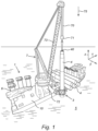
- a vessel 1 which is configured specifically to arrange a foundation for a wind turbine in the form of a monopile 4 in an underwater bottom 5.
- vessel 1 can be equipped with a dynamic positioning system (DP System) to stabilize its position.
- Work deck 10 of vessel 1 supports a hoisting means in the form of a lifting crane 7, provided with a base 72 which is pivotable around a vertical axis and on which is mounted a boom 73 pivotable around a horizontal axis.
- Lifting crane 7 is provided with hoisting cables 70 to which an attaching means in the form of a hoisting block 71 with hook is attached.
- Monopile 4 can be attached to hoisting block 71 at a lifting point 40 and then be taken up by lifting crane 7, and be displaced relative to work deck 10.
- the monopile 4 suspended from hoisting cables 70 can for instance be displaced by rotating base 72, wherein boom 73 will swing over work deck 10, and/or by rotating boom 73 upward (luffing in) or downward (luffing out), wherein monopile 4 is respectively taken up and lowered.
- a guide cage 3 arranged on a side of vessel 1 can be used.
- Other components to be manipulated can be stored on work deck 10 of vessel 1, such as a number of transition pieces 6 of a wind turbine and other monopiles 4.
- FIG. 1 Another application relates to the placing of wind turbine components such as a nacelle 8 on a support structure in the form of a jacket 4' which is already arranged in underwater bottom 5.
- a side view is shown of a vessel 1' configured to assemble a wind turbine on jacket 4' at sea.
- the components of the wind turbine to be placed can comprise a nacelle 8, which is shown in different positions in figures 2A-2B , a mast (section) 8', and/or rotor blades of the wind turbine (not shown).
- Vessel 1' is substantially provided with the same devices as vessel 1, such as for instance a lifting crane 7. For this reason similar devices are numbered the same as in figure 1 .
- hoisting tackle 71 is likewise shown in different positions and the component to be lifted is a nacelle 8.
- Vessel 1' comprises a jack-up offshore platform which is provided with anchor piles 11' which support a work deck 10.
- Anchor piles 11' are movable to the seabed in vertical direction, and the height position of work deck 10 relative to the water level can be changed by displacing work deck 10 relative to piles 11' by means of (hydraulic) jacks or a gear rack-pinion drive system.
- the vessel 1' is moored in the immediate vicinity of a jacket 4' present at sea, and in any case such that jacket 4' lies within reach of lifting crane 7 with boom 73 in luffed-out position.
- boom 73 can comprise a guide device 74 for the hoisting tackle 71, whereby the movement of hoisting tackle 71 can be limited in at least one direction. This is however not essential for the invention.
- Nacelle 8 comprises a housing 80 and a rotatable hub 81 which connects to housing 80 and has mounting points 82 for wind turbine blades.
- Nacelle 8 is suspended by wires (90a, 90b) from an attaching means 9, this comprising in the shown embodiment a first spreader bar 9a and a second spreader part 9b arranged perpendicularly thereof, these together forming a cross-shaped structure.
- Nacelle 8 is suspended with wires (90b, 90a) running respectively between housing 80 and second spreader bar 9b and between hub 81 and first spreader bar 9a.
- first spreader bar 9a is provided with a gyroscope 2.
- FIG. 6 A possible connection between hoisting cable 70 and a monopile foundation 4 is shown in figure 6 .
- Monopile 4 is suspended in slings 93, wherein slings 93 are connected to a spreader bar (not visible) which is provided on an upper side with a work platform 92.
- the spreader bar is in turn connected with slings or cables 90 to a housing 94 for a gyroscope 2.
- Housing 94 is in turn suspended with slings or cables 91 from the hook of hoisting block 71 (also referred to as hoisting tackle 71).
- housing 94 comprises a gyroscope 2.
- Gyroscope 2 comprises a body which rotates around a primary shaft 21 and takes the form of a rotation-symmetrical flywheel 20.
- Primary shaft 21 is suspended rotatably in a first annular suspension 21'.
- the first annular suspension 21' is received in a second annular suspension 22', optionally rotatably around a secondary shaft 22.
- This second annular suspension 22' is suspended, optionally rotatably, in a third suspension 23' with a tertiary shaft 23.
- the third suspension 23' comprises a block provided with a central opening 23a, in which opening 23a the gyroscope 2 is received.
- the block-shaped suspension 23' is arranged in a spreader bar 9a, a housing 94 or another recipient, and anchored rigidly thereto. It is important here that gyroscope 2 is anchored such that the primary rotation shaft 21 runs substantially vertically, in other words runs parallel to the direction 75 of a freely suspended (vertically directed) hoisting cable 70 (or alternatively a plane of the flywheel 20 runs substantially perpendicularly of the direction of a freely suspended hoisting cable 70).
- the couplings between the first 21' and second annular suspension 22' and the third suspension 23' can be freely rotatable but can also each be placed in a fixed position.
- the coupling between the first 21' and the second annular suspension 22' is fixed so that the two rings (21', 22') run orthogonally relative to each other.
- passive, primary shaft 21 of the gyroscope will remain running substantially parallel to the current direction 76 of the swinging hoisting cable 70 in the event of a swinging movement.
- the coupling between the first 21' and the second annular suspension 22' can also be fixed so that the two rings (21', 22') run at an angle 24 other than an orthogonal angle relative to each other.
- the primary shaft 21 of gyroscope 2 will run substantially at said angle 24 relative to the current direction 76 of the swinging hoisting cable 70 in the event of a swinging movement.
- Yet another option lies in releasing the coupling between the first 21' and the second annular suspension 22' so that the two rings (21', 22') can rotate freely relative to each other.
- the coupling between the second annular suspension 22' and the third suspension 23' can be fixed or be released. Releasable couplings for a gyroscope are readily available.
- FIG. 3 an object (4, 8) suspended from a boom 73 with hoisting cable 70 is shown.
- a Cartesian (x, y, z-)coordinate system connected to vessel deck 10 is likewise shown.
- the origin of the (x, y, z-)coordinate system lies at the position of the base 72 of boom 73, or at least in the point around which boom 73 can rotate around base 72.
- the x-axis runs in a longitudinal direction of the ship, the y-axis in a transverse direction of the ship and the z-axis in a direction running perpendicularly of vessel deck 10.
- a suspended object (4, 8) will behave as a pendulum and undergo a swinging movement with substantially three degrees of freedom: an angle ⁇ between hoisting cable 70 and the z-axis, an azimuth angle ⁇ , and an angle of rotation ⁇ of the object (4, 8) around an axis parallel to the current direction 76 of hoisting cable 70.
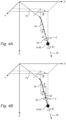
- FIGs 4A and 4B show embodiments of the invented method wherein a gyroscope 2 is incorporated in the hoisting cable 70, for instance in a connecting means 9 for the object (4, 8).
- a method is shown wherein gyroscope 2 is operated in the above described passive state, wherein the primary shaft 21 of gyroscope 2 will remain running substantially parallel to the current direction 76 of the swinging hoisting cable 70 in the event of a swinging movement.
- the rotation vector ⁇ of flywheel 20 is directed parallel to the direction 76, as shown.
- Figure 4B shows a method wherein gyroscope 2 is operated in the above described active state, wherein the primary shaft 21 of gyroscope 2 remains running at an angle other than zero to the current direction 76 of the swinging hoisting cable 70 in the event of a swinging movement.
- the rotation vector ⁇ of flywheel 20 forms here an (acute) angle of inclination ⁇ other than zero with the z-axis.
- gyroscope 2 in the lifting and displacing of an object such as a monopile 4, a nacelle 8 or a mast section 8' of a wind turbine is illustrated by the table included in figure 8 .
- This shows the root mean square ('rms') displacement of the object (4, 8) in the x, y and z-directions in the first three columns, and the maximum displacement occurring in these directions in the final three columns.
- the first row ('uncontrolled pendulum') shows the displacement according to the prior art method.
- the sixth and seventh row show the displacements when the invented method is applied, wherein gyroscope 2 is operated in respectively passive and active state at a rotational speed of 200 revolutions per minute ('rpm'). It will be apparent that all displacements are noticeably reduced (mainly in the x and y-direction) relative to the known method (first row).
- figure 10 illustrates a preferred method in which the floating vessel 1 is held with the x-axis (the longitudinal direction of the ship) substantially parallel to the mean wave direction 100, for instance by an anchoring suitable for this purpose.
- the swinging movements of the fastening means in the form of spreader bar 92 and of the object in the form of a monopile 4 connected thereto are damped substantially parallel to the y-axis (the transverse direction of the ship) using tugger lines 101.
- tugger lines 101 are connected to winches 102 anchored to work deck 10, wherein the winches 102 are able to pay out or take in the tugger lines.
- the swinging movements in the x-direction are damped by a gyroscope 2 received in housing 94, as described above.
Landscapes
- Engineering & Computer Science (AREA)
- Mechanical Engineering (AREA)
- General Engineering & Computer Science (AREA)
- Civil Engineering (AREA)
- Structural Engineering (AREA)
- Sustainable Development (AREA)
- Life Sciences & Earth Sciences (AREA)
- Sustainable Energy (AREA)
- Chemical & Material Sciences (AREA)
- Combustion & Propulsion (AREA)
- Wind Motors (AREA)
- Load-Engaging Elements For Cranes (AREA)
- Jib Cranes (AREA)
Description
- The present invention relates to a method for lifting an object from a vessel deck, wherein a hoisting means on the vessel deck comprises a hoisting cable which is provided at an outer end with an attaching means for the object, wherein the object is connected to the attaching means and the object is taken up and displaced relative to the vessel deck using the attaching means.
- The invention will be described partly in respect of an offshore wind turbine. The reference to such a wind turbine however does not imply that the invention is limited to taking up and displacing wind turbine components, and the method can likewise be applied for taking up and displacing any other object, particularly a large and slender object.
- The taking up and displacing of an object from a vessel deck can for instance be applied during the placing of a wind turbine at sea. Components of the wind turbine must be placed from a vessel deck onto a support structure placed at sea, and this entails taking up and displacing of the wind turbine component from a vessel deck. An offshore wind turbine comprises a gondola (or nacelle) which is placed on a mast and forms the housing for electromechanical equipment such as a power generator. The nacelle is provided with a hub on which a number of rotor blades are arranged. The rotor blades convert the kinetic energy of the wind into a rotating movement of the shaft of the nacelle, which is converted into electrical energy by the power generator. Depending on the stage of construction, the support structure can, in the case of a wind turbine, comprise a foundation, a mast placed on the foundation or a nacelle placed on the mast. A mast, a nacelle or a turbine blade must then respectively be placed here.
- The lifting and placing of objects such as said wind turbine components is hampered by wind and wave load. This will increasingly be the case the greater and slenderer the object is. Wind turbine blades in particular catch a lot of wind. Wind turbine blades attached to the hoisting means can be exposed here to great and unexpected movements relative to the support structure or relative to already installed components. This makes the operations considerably more difficult, or even impossible in the case of strong wind load. In addition, the objects are taken up from a vessel deck, wherein the vessel is subject to movements caused by wave action.
- A vessel floating on water is exposed to movements having 6 degrees of freedom, including three translating movements and three rotation movements. In a Cartesian coordinate system coupled to the vessel deck an x-axis runs parallel to the longitudinal direction of the vessel, a y-axis parallel to a transverse direction of the vessel and a z-axis parallel to a direction running perpendicularly of the vessel deck. A translation of the vessel in the x-direction is referred to as surge, a translation of the vessel in the y-direction as sway and a translation of the vessel in the z-direction as heave. A rotation of the vessel around the x-axis is referred to as roll, a rotation around the y-axis as pitch, and a rotation around the z-axis as yaw. All these movements can induce swinging movements of an object suspended from the hoisting means, particularly in that a hoisting means present on the vessel deck will follow the vessel movements.
-
WO 2018/113882A1 discloses an assembly for rotating a suspended load such as wind turbine related components around a vertical axis. The assembly comprises an inner rim to which the load is suspended and an outer rim that may be held in a fixed position. A drive rotates the inner rim and the load suspended from it relative to the outer rim. -
KR 101607995 KR 101607995 - JPH02169493 and
JP5644419 -
WO2017/059493 also discloses a method for controlling the orientation of a lifted load by means of two or more gyroscopes.WO2017/059493 also is not related to a method for damping the swinging movements of a suspended load. The same holds forWO 2015/082347 . -
US 5,871,249 finally discloses a gyroscopically stabilized positioning system that is resistant to external forces. A plurality of drivable flywheels is rigidly engaged to a suspended load, and each arranged along one of a set of three orthogonal space axes. These axes are fixed with respect to the hoisting cable direction.WO 2018/192675 discloses a method for lifting an object from a vessel deck, wherein a hoisting means on the vessel deck comprises a hoisting cable which is provided at an outer end with an attaching means for the object, wherein the object is connected to the attaching means and the object is taken up and displaced relative to the vessel deck using the attaching means, wherein the swinging movements of the attaching means and of the object connected thereto, occurring under the influence of wave and wind forces, are damped during displacement by a gyroscope which is connected to the hoisting cable, attaching means and/or object and which comprises a rotation-symmetrical body rotating around a primary rotation axis, whereby the primary rotation axis of the gyroscope is held at an angle of inclination other than zero to the hoisting cable direction. - The vessel from which the object is taken up and displaced can comprise a jack-up platform, wherein the legs of the jack-up platform resting on the seabed provide for some stability. The advantages of the invention however become most clearly manifest when the vessel is a floating vessel.
- An object of the present invention is to provide a method with which, using an attaching means, an object can be taken up and displaced relative to a vessel deck at sea, and can optionally be placed and mounted on a support structure present in the sea, in a manner less susceptible to wind than is known in the prior art.
- This object is achieved by providing a method according to
claim 1. The invention particularly provides a method for lifting an object from a vessel deck, wherein a hoisting means on the vessel deck comprises a hoisting cable which is provided at an outer end with an attaching means for the object. The object is connected to the attaching means and then taken up and displaced relative to the vessel deck using the attaching means. The swinging movements of the attaching means and of the object connected thereto, occurring under the influence of wave and wind forces, are damped during displacement by a gyroscope which is connected to the hoisting cable, attaching means and/or object and which comprises a rotation-symmetrical body rotating around a primary rotation axis. - The gyroscope damps the swinging movements, occurring due to wave and wind forces, of the attaching means and of the object connected thereto, which is understood to mean that an amplitude of the swinging movements in different directions is lower than the amplitude of these swinging movements when the gyroscope is not used. In this way an object can be manipulated with a hoisting means from a vessel deck in rougher weather conditions than is possible according to the prior art.
- A gyroscope is per se known and is for instance applied in vessels for the purpose of reducing rolling movements (roll) of the vessel. This involves controlling a movement in one single direction. An object suspended in a hoisting cable is however subject to movements in all directions, caused by the above stated vessel movements (surge, sway, heave, roll, pitch and yaw), and wind forces. It is surprising that a single gyroscope connected to the hoisting cable, attaching means and/or object is able to damp the swinging movements in all directions in effective manner. Damping the swinging of an object suspended from a lifting means achieves that the position of the object becomes more accurate during displacement of the object relative to the vessel deck. Such a displacement can be achieved by displacing the part of the lifting means to which the hoisting cable is connected (for instance an outer end of a boom) relative to the vessel deck. This movement can also cause additional swinging movements of the suspended object.
- A gyroscope comprises a rotation-symmetrical body rotating around a primary rotation axis. This rotating body is set into rotation with a drive suitable for this purpose, wherein the rotation speed can be kept constant or can be varied, for instance accelerated. The body can be disc-like (for instance a flywheel), but can also take on a different form, such as for instance a spherical form. The body is received via the primary rotation shaft in a suspension suitable for this purpose, for instance in a frame or housing.
- According to the invention, the method has the feature that the primary rotation axis of the gyroscope is held at an angle of inclination other than zero to the current hoisting cable direction.
- According to the invention, the angle of inclination is varied linearly with the current angle of swing between the hoisting cable direction and the z-direction running perpendicularly of the vessel deck.
- An embodiment of the method wherein the speed of rotation of the body rotating around the primary rotation axis is increased as an amplitude of the swinging movement increases has been found to result in a further stabilization of the suspended object.
- The invented method can be applied in different stages of the manipulation of an object connected to the attaching means. Provided in particular is an embodiment of the method wherein the swinging movements of the attaching means and of the object connected thereto are damped by the gyroscope during taking up of the object from the vessel deck. During transport over sea objects are usually situated on the vessel deck in a storage provided for this purpose. An object must be taken up from such a storage, wherein the hoisting cable can have a maximum length when taking up and the hoisting cable can be hauled in to a minimum length during lifting. It has been found that the gyroscope also operates well and prevents swinging movements of the object in this stage of the manipulation, also during hauling in of the hoisting cable. This enhances the safety on the vessel deck.
- According to another embodiment, the invented method can also applied such that the taken-up and displaced object is lowered and mounted on a support structure for the object present in the surrounding water, and the swinging movements of the attaching means and of the object connected thereto are damped by the gyroscope during lowering and/or mounting of the object on the support structure. It is important here to consider that the support structure is generally in a relatively stable position relative to the seabed, and the suspended object thus moves relative to the support structure. The method according to the present embodiment ensures that this relative movement is damped.
- Yet another embodiment of the invention provides a method wherein the hoisting means comprises a boom, to an outer end of which the hoisting cable is connected, and the boom is rotated, at least during displacement of the object, around a rotation axis running perpendicularly of the vessel deck. Such a method of lifting, wherein a suspension point (an outer end of the boom to which the hoisting cable is attached) itself is moved, can cause additional swinging movements of the object due to this movement. A good damping of the swinging movements is also achieved in this embodiment.
- A further improved method relates to an embodiment in which the swinging movements of the attaching means and of the object connected thereto are damped further by connecting tugger lines on one side to the attaching means and/or to the object connected thereto, and holding the tugger lines on another side, preferably from the vessel deck. In this embodiment the swinging movements can further be damped by taking in or paying out the tugger lines.
- Yet another embodiment relates to a method wherein the swinging movements of the attaching means and of the object connected thereto are damped by the tugger lines in a direction other than the direction in which the gyroscope produces a maximum damping of the swinging movements.
- It can have further advantages here to apply a method according to an embodiment wherein an (x, y, z-)coordinate system is connected to the vessel deck, wherein the x-axis runs in a longitudinal direction of the vessel, the y-axis in a transverse direction of the vessel, and the z-axis in a direction running perpendicularly of the vessel deck, wherein the vessel is held with the x-axis substantially parallel to the wave direction and the swinging movements of the attaching means and of the object connected thereto are damped substantially parallel to the y-axis using the tugger lines.
- According to the invention, the gyroscope can be attached to any component suspended from the hoisting cable, in addition to a possible attachment to the hoisting cable itself. In a practical embodiment of the method the attaching means comprises the gyroscope. The attaching means can comprise a spreader bar from which the object is suspended, or the attaching means can comprise a hoisting block.
- According to an embodiment, a method is provided wherein the body of the gyroscope rotating around the primary rotation axis is received in a frame or housing, wherein the body is driven rotationally by drive means and wherein the frame or the housing is connected, optionally fixedly, to the hoisting cable, the attaching means and/or the object. The connection can also be realized by means of slings or cables.
- With the invented method any object suspended from a hoisting cable can in principle be manipulated from a vessel deck. The invention has particular advantages in an embodiment of the method wherein the object comprises a mast section, a rotor blade and/or the nacelle of a wind turbine, more particularly wherein the object comprises the nacelle with hub of a wind turbine, and the hub is provided with a rotor blade, preferably three rotor blades.
- The invention will now be further elucidated with reference to the following figures and description of preferred embodiments, without the invention otherwise being limited thereto. In the figures:
-
Fig. 1 shows a schematic perspective view of a floating vessel configured to lift an object from its vessel deck as according to an embodiment of the invention; -
Fig. 2A-2B show a schematic side view and rear view of a jack-up platform configured to lift an object and to place the object on a support structure as according to an embodiment of the invention, in different states; -
Fig. 3 shows a schematic representation of the degrees of freedom of an object suspended from a boom of a hoisting means as according to the prior art; -
Fig. 4A and 4B show schematic representations of the degrees of freedom of an object suspended from a boom of a hoisting means as according to two embodiments of the invention; -
Fig. 5 shows a schematic perspective view of a wind turbine nacelle suspended from an attaching means as according to an embodiment of the invention; -
Fig. 6 shows a schematic perspective view of a monopile foundation for a wind turbine suspended from an attaching means as according to an embodiment of the invention; -
Fig. 7 shows a schematic perspective view of an embodiment of a gyroscope configured for application in the method according to the invention; -
Fig. 8 shows a comparative table which clarifies the damping effect of an embodiment of the gyroscope on swinging movements of a suspended object; -
Fig. 9A, 9B and 9C show the probability distribution of the position in the x, y and z-direction of an object suspended as according to the prior art and as according to embodiments of the invention; and, finally -
Fig. 10 shows a schematic top view of a method according to a specific embodiment of the invention. - Referring to
figure 1 , avessel 1 is shown which is configured specifically to arrange a foundation for a wind turbine in the form of amonopile 4 in anunderwater bottom 5. If desired,vessel 1 can be equipped with a dynamic positioning system (DP System) to stabilize its position.Work deck 10 ofvessel 1 supports a hoisting means in the form of a liftingcrane 7, provided with a base 72 which is pivotable around a vertical axis and on which is mounted aboom 73 pivotable around a horizontal axis. Liftingcrane 7 is provided with hoistingcables 70 to which an attaching means in the form of ahoisting block 71 with hook is attached.Monopile 4 can be attached to hoistingblock 71 at a lifting point 40 and then be taken up by liftingcrane 7, and be displaced relative to workdeck 10. Themonopile 4 suspended from hoistingcables 70 can for instance be displaced by rotatingbase 72, whereinboom 73 will swing overwork deck 10, and/or by rotatingboom 73 upward (luffing in) or downward (luffing out), whereinmonopile 4 is respectively taken up and lowered. In order to finallylower monopile 4 into underwater bottom 5 aguide cage 3 arranged on a side ofvessel 1 can be used. Other components to be manipulated can be stored onwork deck 10 ofvessel 1, such as a number oftransition pieces 6 of a wind turbine andother monopiles 4. - It will be apparent that the lifting and placing of the
monopile 4 is hampered by wind load, whereinvessel 1 is also subject to movements caused by wave action. The freely suspendedmonopile 4 taken up with liftingcrane 7 can be exposed to great and unexpected swinging movements relative toword deck 10, guidecage 3 andunderwater bottom 5. This makes the operations considerably more difficult, or even impossible in the case of strong wind load. - Another application relates to the placing of wind turbine components such as a
nacelle 8 on a support structure in the form of a jacket 4' which is already arranged inunderwater bottom 5. Referring tofigures 2A and 2B , a side view is shown of a vessel 1' configured to assemble a wind turbine on jacket 4' at sea. The components of the wind turbine to be placed can comprise anacelle 8, which is shown in different positions infigures 2A-2B , a mast (section) 8', and/or rotor blades of the wind turbine (not shown). Vessel 1' is substantially provided with the same devices asvessel 1, such as for instance a liftingcrane 7. For this reason similar devices are numbered the same as infigure 1 . Infigures 2A- 2B hoisting tackle 71 is likewise shown in different positions and the component to be lifted is anacelle 8. Vessel 1' comprises a jack-up offshore platform which is provided with anchor piles 11' which support awork deck 10. Anchor piles 11' are movable to the seabed in vertical direction, and the height position ofwork deck 10 relative to the water level can be changed by displacingwork deck 10 relative topiles 11' by means of (hydraulic) jacks or a gear rack-pinion drive system. In order to enable the method according to the invention to be performed the vessel 1' is moored in the immediate vicinity of a jacket 4' present at sea, and in any case such that jacket 4' lies within reach of liftingcrane 7 withboom 73 in luffed-out position. - If desired,
boom 73 can comprise aguide device 74 for the hoistingtackle 71, whereby the movement of hoistingtackle 71 can be limited in at least one direction. This is however not essential for the invention. - In both above stated illustrative applications swinging movements of hoisting
tackle 71 and of thenacelle 8 connected thereto occurring under the influence of wave and wind forces are according to the invention damped during displacement by agyroscope 2 which is connected to hoisting tackle 71 ornacelle 8 itself and which comprises a rotation-symmetrical body rotating around a primary rotation axis. - A possible connection between hoisting
cable 70 and forinstance nacelle 8 is shown infigure 5 .Nacelle 8 comprises ahousing 80 and arotatable hub 81 which connects tohousing 80 and has mountingpoints 82 for wind turbine blades.Nacelle 8 is suspended by wires (90a, 90b) from an attachingmeans 9, this comprising in the shown embodiment afirst spreader bar 9a and asecond spreader part 9b arranged perpendicularly thereof, these together forming a cross-shaped structure.Nacelle 8 is suspended with wires (90b, 90a) running respectively betweenhousing 80 andsecond spreader bar 9b and betweenhub 81 andfirst spreader bar 9a. According to this embodiment,first spreader bar 9a is provided with agyroscope 2. - A possible connection between hoisting
cable 70 and amonopile foundation 4 is shown infigure 6 .Monopile 4 is suspended inslings 93, wherein slings 93 are connected to a spreader bar (not visible) which is provided on an upper side with awork platform 92. The spreader bar is in turn connected with slings orcables 90 to ahousing 94 for agyroscope 2.Housing 94 is in turn suspended with slings orcables 91 from the hook of hoisting block 71 (also referred to as hoisting tackle 71). According to this embodiment,housing 94 comprises agyroscope 2. - A possible embodiment of a
gyroscope 2 received in ahousing 94 orspreader bar 9a is shown infigure 7 .Gyroscope 2 comprises a body which rotates around aprimary shaft 21 and takes the form of a rotation-symmetrical flywheel 20.Primary shaft 21 is suspended rotatably in a first annular suspension 21'. The first annular suspension 21' is received in a second annular suspension 22', optionally rotatably around asecondary shaft 22. This second annular suspension 22' is suspended, optionally rotatably, in a third suspension 23' with atertiary shaft 23. In the shown embodiment the third suspension 23' comprises a block provided with acentral opening 23a, in whichopening 23a thegyroscope 2 is received. The block-shaped suspension 23' is arranged in aspreader bar 9a, ahousing 94 or another recipient, and anchored rigidly thereto. It is important here that gyroscope 2 is anchored such that theprimary rotation shaft 21 runs substantially vertically, in other words runs parallel to thedirection 75 of a freely suspended (vertically directed) hoisting cable 70 (or alternatively a plane of theflywheel 20 runs substantially perpendicularly of the direction of a freely suspended hoisting cable 70). - The couplings between the first 21' and second annular suspension 22' and the third suspension 23' can be freely rotatable but can also each be placed in a fixed position. In the shown embodiment the coupling between the first 21' and the second annular suspension 22' is fixed so that the two rings (21', 22') run orthogonally relative to each other. In this state, referred to as passive,
primary shaft 21 of the gyroscope will remain running substantially parallel to thecurrent direction 76 of theswinging hoisting cable 70 in the event of a swinging movement. The coupling between the first 21' and the second annular suspension 22' can also be fixed so that the two rings (21', 22') run at an angle 24 other than an orthogonal angle relative to each other. In this state, referred to as active, theprimary shaft 21 ofgyroscope 2 will run substantially at said angle 24 relative to thecurrent direction 76 of theswinging hoisting cable 70 in the event of a swinging movement. Yet another option lies in releasing the coupling between the first 21' and the second annular suspension 22' so that the two rings (21', 22') can rotate freely relative to each other. In the above stated embodiments the coupling between the second annular suspension 22' and the third suspension 23' can be fixed or be released. Releasable couplings for a gyroscope are readily available. - Referring to
figure 3 , an object (4, 8) suspended from aboom 73 with hoistingcable 70 is shown. A Cartesian (x, y, z-)coordinate system connected tovessel deck 10 is likewise shown. The origin of the (x, y, z-)coordinate system lies at the position of thebase 72 ofboom 73, or at least in the point around which boom 73 can rotate aroundbase 72. The x-axis runs in a longitudinal direction of the ship, the y-axis in a transverse direction of the ship and the z-axis in a direction running perpendicularly ofvessel deck 10. As shown, under the influence of wave and wind forces a suspended object (4, 8) will behave as a pendulum and undergo a swinging movement with substantially three degrees of freedom: an angle θ between hoistingcable 70 and the z-axis, an azimuth angle ψ, and an angle of rotation φ of the object (4, 8) around an axis parallel to thecurrent direction 76 of hoistingcable 70. -
Figures 4A and 4B show embodiments of the invented method wherein agyroscope 2 is incorporated in the hoistingcable 70, for instance in a connectingmeans 9 for the object (4, 8). Infigure 4A a method is shown whereingyroscope 2 is operated in the above described passive state, wherein theprimary shaft 21 ofgyroscope 2 will remain running substantially parallel to thecurrent direction 76 of theswinging hoisting cable 70 in the event of a swinging movement. In other words, the rotation vector ω offlywheel 20 is directed parallel to thedirection 76, as shown.Figure 4B shows a method whereingyroscope 2 is operated in the above described active state, wherein theprimary shaft 21 ofgyroscope 2 remains running at an angle other than zero to thecurrent direction 76 of theswinging hoisting cable 70 in the event of a swinging movement. In other words, the rotation vector ω offlywheel 20 forms here an (acute) angle of inclination β other than zero with the z-axis. - The effect of
gyroscope 2 in the lifting and displacing of an object such as amonopile 4, anacelle 8 or a mast section 8' of a wind turbine is illustrated by the table included infigure 8 . This shows the root mean square ('rms') displacement of the object (4, 8) in the x, y and z-directions in the first three columns, and the maximum displacement occurring in these directions in the final three columns. The first row ('uncontrolled pendulum') shows the displacement according to the prior art method. The second and third row ('passive gyroscope 150 rpm', 'active gyroscope 150 rpm') show the displacements when the invented method is applied, whereingyroscope 2 is operated in respectively passive and active state at a rotational speed of 150 revolutions per minute ('rpm'). The fourth and fifth row ('passive gyroscope 180 rpm', 'active gyroscope 180 rpm') show the displacements when the invented method is applied, whereingyroscope 2 is operated in respectively passive and active state at a rotational speed of 180 revolutions per minute ('rpm'). Finally, the sixth and seventh row ('passive gyroscope 200 rpm', 'active gyroscope 200 rpm') show the displacements when the invented method is applied, whereingyroscope 2 is operated in respectively passive and active state at a rotational speed of 200 revolutions per minute ('rpm'). It will be apparent that all displacements are noticeably reduced (mainly in the x and y-direction) relative to the known method (first row). - This effect is also visible in
figures 9A, 9B and 9C , in which the probability P(x, y, z) of positions of the object (4, 8) in the x, y and z-direction are shown as a function of the displacement. A method according to the invention has been found to noticeably reduce the amplitude of the swinging movement, mainly in the x and the y-direction. The swinging movement is thus damped efficiently. - Finally,
figure 10 illustrates a preferred method in which the floatingvessel 1 is held with the x-axis (the longitudinal direction of the ship) substantially parallel to themean wave direction 100, for instance by an anchoring suitable for this purpose. The swinging movements of the fastening means in the form ofspreader bar 92 and of the object in the form of amonopile 4 connected thereto are damped substantially parallel to the y-axis (the transverse direction of the ship) usingtugger lines 101. For this purpose tuggerlines 101 are connected towinches 102 anchored to workdeck 10, wherein thewinches 102 are able to pay out or take in the tugger lines. The swinging movements in the x-direction are damped by agyroscope 2 received inhousing 94, as described above. - The invention is not limited to the embodiments shown in the figures, and many variants thereof are possible within the scope of protection of the appended claims.
Claims (14)
- Method for lifting an object from a vessel deck (10), wherein a hoisting means (7) on the vessel deck comprises a hoisting cable (70) which is provided at an outer end with an attaching means (71) for the object, wherein the object is connected to the attaching means and the object is taken up and displaced relative to the vessel deck using the attaching means, wherein the swinging movements of the attaching means and of the object connected thereto, occurring under the influence of wave and wind forces, are damped during displacement by a gyroscope (2) which is connected to the hoisting cable, attaching means and/or object and which comprises a rotation-symmetrical body (20) rotating around a primary rotation axis, wherein the primary rotation axis of the gyroscope is held at an angle of inclination other than zero to the hoisting cable direction, wherein the angle of inclination is varied linearly with the current angle of swing between the hoisting cable direction and the z-direction running perpendicularly of the vessel deck.
- Method according to claim 1, wherein the speed of rotation of the body rotating around the primary rotation axis is increased as an amplitude of the swinging movement increases.
- Method according to any one of the foregoing claims, wherein the swinging movements of the attaching means and of the object connected thereto are damped by the gyroscope during taking up of the object from the vessel deck.
- Method according to any one of the foregoing claims, wherein the taken-up and displaced object is lowered and mounted on a support structure (4) for the object present in the surrounding water, and the swinging movements of the attaching means and of the object connected thereto are damped by the gyroscope during lowering and/or mounting of the object on the support structure.
- Method according to any one of the foregoing claims, wherein the hoisting means comprises a boom (73), to an outer end of which the hoisting cable is connected, and the boom is rotated, at least during displacement of the object, around a rotation axis running perpendicularly of the vessel deck.
- Method according to any one of the foregoing claims, wherein the swinging movements of the attaching means and of the object connected thereto are damped further by connecting tugger lines (101) on one side to the attaching means and/or to the object connected thereto, and holding the tugger lines on another side, preferably from the vessel deck, wherein the swinging movements are further damped by taking in or paying out the tugger lines.
- Method according to claim 6, wherein the swinging movements of the attaching means and of the object connected thereto are damped by the tugger lines in a direction other than the direction in which the gyroscope produces a maximum damping of the swinging movements.
- Method according to any one of the claims 6 and 7, wherein an (x, y, z-)coordinate system is connected to the vessel deck, wherein the x-axis runs in a longitudinal direction of the vessel, the y-axis in a transverse direction of the vessel, and the z-axis in a direction running perpendicularly of the vessel deck, wherein the vessel is held with the x-axis substantially parallel to the wave direction and the swinging movements of the attaching means and of the object connected thereto are damped substantially parallel to the y-axis using the tugger lines.
- Method according to any one of the foregoing claims, wherein the attaching means comprises the gyroscope.
- Method according to any one of the foregoing claims, wherein the attaching means comprises a spreader bar (9) from which the object is suspended.
- Method according to any one of the foregoing claims, wherein the attaching means comprises a hoisting block. block (71).
- Method according to any one of the foregoing claims, wherein the body of the gyroscope rotating around the primary rotation axis is received in a frame, wherein the body is driven rotationally by drive means and wherein the frame is connected fixedly to the hoisting cable, the attaching means and/or the object.
- Method according to any one of the foregoing claims, wherein the object comprises a mast section (8'), a rotor blade and/or the nacelle (8) of a wind turbine.
- Method according to claim 13, wherein the object comprises the nacelle with hub of a wind turbine, and the hub is provided with a rotor blade, preferably three rotor blades.
Applications Claiming Priority (2)
| Application Number | Priority Date | Filing Date | Title |
|---|---|---|---|
| BE20195565A BE1027530B1 (en) | 2019-08-29 | 2019-08-29 | Method of lifting an object from a vessel deck |
| PCT/EP2020/074108 WO2021038057A1 (en) | 2019-08-29 | 2020-08-28 | Method for lifting an object from a vessel deck |
Publications (2)
| Publication Number | Publication Date |
|---|---|
| EP4021838A1 EP4021838A1 (en) | 2022-07-06 |
| EP4021838B1 true EP4021838B1 (en) | 2025-05-21 |
Family
ID=67997307
Family Applications (1)
| Application Number | Title | Priority Date | Filing Date |
|---|---|---|---|
| EP20760888.6A Active EP4021838B1 (en) | 2019-08-29 | 2020-08-28 | Method for lifting an object from a vessel deck |
Country Status (8)
| Country | Link |
|---|---|
| US (1) | US12528671B2 (en) |
| EP (1) | EP4021838B1 (en) |
| JP (1) | JP7566885B2 (en) |
| BE (1) | BE1027530B1 (en) |
| DK (1) | DK4021838T3 (en) |
| PL (1) | PL4021838T3 (en) |
| TW (1) | TWI879792B (en) |
| WO (1) | WO2021038057A1 (en) |
Families Citing this family (8)
| Publication number | Priority date | Publication date | Assignee | Title |
|---|---|---|---|---|
| US11976632B2 (en) * | 2020-07-09 | 2024-05-07 | Vestas Wind Systems A/S | Mass damper module for wind turbine installation |
| NL2028741B1 (en) * | 2021-07-15 | 2023-01-23 | Itrec Bv | upend crane and installation vessel |
| JP2024519473A (en) * | 2021-04-30 | 2024-05-14 | イーテーエルエーセー・ベー・フェー | Erection crane and installation vessel |
| US12577942B2 (en) | 2021-09-16 | 2026-03-17 | Crowley New Energy, Inc. | Methods of securing a vessel during transportation, off-loading, and installation of wind turbine components |
| EP4253302A1 (en) | 2022-03-29 | 2023-10-04 | Siemens Gamesa Renewable Energy A/S | Method for lifting a wind turbine rotor blade and lifting yoke |
| IT202200006833A1 (en) * | 2022-04-06 | 2023-10-06 | Saipem Spa | System and method of transferring pipeline pipes, in particular from a pipe carrier to a pipeline vessel or an offshore facility |
| CN116306307B (en) * | 2023-03-31 | 2025-09-05 | 中国船舶科学研究中心 | Total longitudinal stress field reconstruction method and device suitable for ships under actual sea conditions |
| CN120348839B (en) * | 2025-06-24 | 2025-09-19 | 江苏扬阳化工设备制造有限公司 | A large glass-lined equipment firing crane |
Citations (15)
| Publication number | Priority date | Publication date | Assignee | Title |
|---|---|---|---|---|
| DE2035367A1 (en) | 1970-07-16 | 1972-01-20 | Tax H | Gyro system for the orientation of hanging loads |
| JPH02169493A (en) | 1988-12-23 | 1990-06-29 | Ohbayashi Corp | Attitude controller for suspended load |
| JPH0680383A (en) | 1992-07-01 | 1994-03-22 | Mitsubishi Heavy Ind Ltd | Slewing control device of suspending/holding device |
| US5632222A (en) | 1992-11-07 | 1997-05-27 | Fido; Peter M. | Load orientating device |
| US5871249A (en) | 1996-11-12 | 1999-02-16 | Williams; John H. | Stable positioning system for suspended loads |
| US20040244513A1 (en) | 2003-06-04 | 2004-12-09 | Adams John D. | Gyroscopic roll stabilizer for boats |
| EP2123588A1 (en) | 2008-05-21 | 2009-11-25 | Liebherr-Werk Nenzing GmbH | Crane control with active swell sequence |
| US8899166B2 (en) | 2010-02-17 | 2014-12-02 | Veem Ltd. | Active adaptive gyrostabiliser control system |
| JP5644419B2 (en) | 2010-11-24 | 2014-12-24 | 株式会社大林組 | Suspension swivel device and method |
| WO2015082347A1 (en) | 2013-12-02 | 2015-06-11 | Savant Tech As | Method and system for controlling a load |
| KR20150102518A (en) | 2014-02-28 | 2015-09-07 | 삼성중공업 주식회사 | Lifting device |
| US9919901B2 (en) | 2013-11-25 | 2018-03-20 | Vinati S.R.L. | Device and a process for controlling a swinging of a load suspended from a lifting apparatus |
| WO2018113882A1 (en) | 2016-12-22 | 2018-06-28 | Mhi Vestas Offshore Wind A/S | Assembly for rotating a suspended load |
| EP3359480A1 (en) | 2015-10-08 | 2018-08-15 | Verton Technologies Australia Pty Ltd | Materials management systems and methods |
| WO2018192675A1 (en) | 2017-04-18 | 2018-10-25 | Siemens Wind Power A/S | Method for installing components of a wind turbine |
Family Cites Families (21)
| Publication number | Priority date | Publication date | Assignee | Title |
|---|---|---|---|---|
| JPS5644419A (en) | 1979-09-20 | 1981-04-23 | Honda Motor Co Ltd | Device for improving combustion of mixture in four-cycle internal combustion engine |
| JPS6356179U (en) * | 1986-09-29 | 1988-04-14 | ||
| JPH06341485A (en) * | 1993-05-31 | 1994-12-13 | Mitsubishi Heavy Ind Ltd | Rotational swinging damping device of suspended object |
| JP3342162B2 (en) * | 1994-03-31 | 2002-11-05 | 三菱重工業株式会社 | Hanging posture control device using gyroscope and control method thereof |
| US7426423B2 (en) * | 2003-05-30 | 2008-09-16 | Liebherr-Werk Nenzing—GmbH | Crane or excavator for handling a cable-suspended load provided with optimised motion guidance |
| JP2004001750A (en) * | 2003-06-25 | 2004-01-08 | Penta Ocean Constr Co Ltd | Construction of special work boats and offshore structures |
| GB2451093B (en) * | 2007-07-17 | 2009-12-02 | Royal Shakespeare Company | Oscillation damper |
| DE102011102025A1 (en) * | 2011-05-19 | 2012-11-22 | Liebherr-Werk Nenzing Gmbh | crane control |
| NL2007761C2 (en) * | 2011-11-09 | 2013-05-13 | Ihc Holland Ie Bv | Vessel and crane with full dynamic compensation for vessel and wave motions. |
| NO2879984T3 (en) | 2012-08-06 | 2018-09-22 | ||
| US10322913B2 (en) * | 2013-02-18 | 2019-06-18 | High Wind N.V. | Device and method for placing a rotor blade of a wind turbine |
| US9731798B2 (en) * | 2013-03-25 | 2017-08-15 | Nauti-Craft Pty Ltd | Stabilising of marine bodies |
| US8938325B1 (en) * | 2013-09-24 | 2015-01-20 | The United States Of America As Represented By The Secretary Of The Navy | Control system for stabilizing a single line suspended mass in yaw |
| KR101649942B1 (en) * | 2014-07-09 | 2016-08-30 | 주식회사 포스코건설 | System to control attitude of lifting loads using gyroscope effect and operation method thereof |
| JP6605840B2 (en) * | 2015-05-13 | 2019-11-13 | 鹿島建設株式会社 | Suspended load attitude control device |
| JP6378250B2 (en) * | 2016-05-20 | 2018-08-22 | 三菱重工業株式会社 | Suspended load elevating apparatus and method for elevating suspended load for wind power generator |
| CN109690073B (en) * | 2016-09-02 | 2020-06-30 | 挪威国立奥伊威尔瓦克有限公司 | Method for building an offshore windmill |
| NL2017937B1 (en) | 2016-12-06 | 2018-06-19 | Itrec Bv | A wave-induced motion compensating crane for use on an offshore vessel, vessel and load transferring method |
| EP3615467B1 (en) | 2017-04-24 | 2024-03-27 | Itrec B.V. | A motion compensating crane for use on an offshore vessel |
| NL2020389B1 (en) | 2018-02-06 | 2019-08-14 | Itrec Bv | A crane |
| CN109534188B (en) * | 2018-11-16 | 2020-12-08 | 山东大学 | A rigid-flexible hybrid wave motion compensation device for an offshore floating hoisting platform |
-
2019
- 2019-08-29 BE BE20195565A patent/BE1027530B1/en active IP Right Grant
-
2020
- 2020-08-27 TW TW109129363A patent/TWI879792B/en active
- 2020-08-28 PL PL20760888.6T patent/PL4021838T3/en unknown
- 2020-08-28 EP EP20760888.6A patent/EP4021838B1/en active Active
- 2020-08-28 DK DK20760888.6T patent/DK4021838T3/en active
- 2020-08-28 JP JP2022513325A patent/JP7566885B2/en active Active
- 2020-08-28 WO PCT/EP2020/074108 patent/WO2021038057A1/en not_active Ceased
- 2020-08-28 US US17/638,263 patent/US12528671B2/en active Active
Patent Citations (15)
| Publication number | Priority date | Publication date | Assignee | Title |
|---|---|---|---|---|
| DE2035367A1 (en) | 1970-07-16 | 1972-01-20 | Tax H | Gyro system for the orientation of hanging loads |
| JPH02169493A (en) | 1988-12-23 | 1990-06-29 | Ohbayashi Corp | Attitude controller for suspended load |
| JPH0680383A (en) | 1992-07-01 | 1994-03-22 | Mitsubishi Heavy Ind Ltd | Slewing control device of suspending/holding device |
| US5632222A (en) | 1992-11-07 | 1997-05-27 | Fido; Peter M. | Load orientating device |
| US5871249A (en) | 1996-11-12 | 1999-02-16 | Williams; John H. | Stable positioning system for suspended loads |
| US20040244513A1 (en) | 2003-06-04 | 2004-12-09 | Adams John D. | Gyroscopic roll stabilizer for boats |
| EP2123588A1 (en) | 2008-05-21 | 2009-11-25 | Liebherr-Werk Nenzing GmbH | Crane control with active swell sequence |
| US8899166B2 (en) | 2010-02-17 | 2014-12-02 | Veem Ltd. | Active adaptive gyrostabiliser control system |
| JP5644419B2 (en) | 2010-11-24 | 2014-12-24 | 株式会社大林組 | Suspension swivel device and method |
| US9919901B2 (en) | 2013-11-25 | 2018-03-20 | Vinati S.R.L. | Device and a process for controlling a swinging of a load suspended from a lifting apparatus |
| WO2015082347A1 (en) | 2013-12-02 | 2015-06-11 | Savant Tech As | Method and system for controlling a load |
| KR20150102518A (en) | 2014-02-28 | 2015-09-07 | 삼성중공업 주식회사 | Lifting device |
| EP3359480A1 (en) | 2015-10-08 | 2018-08-15 | Verton Technologies Australia Pty Ltd | Materials management systems and methods |
| WO2018113882A1 (en) | 2016-12-22 | 2018-06-28 | Mhi Vestas Offshore Wind A/S | Assembly for rotating a suspended load |
| WO2018192675A1 (en) | 2017-04-18 | 2018-10-25 | Siemens Wind Power A/S | Method for installing components of a wind turbine |
Non-Patent Citations (7)
| Title |
|---|
| "Master's Thesis, Iowa State University", 1 January 2013, article WALCK CHRISTOPHER JOEL: "Stabilization of an inverted pendulum using control moment gyros", XP093370761 |
| ANONYMOUS: "Gyroscopic Stabilizers For Construction Cranes And Gondolas", CONSTRUCTION INDUSTRY COUNCIL, 1 January 2018 (2018-01-01), XP093370768 |
| INOUE FUMIHIRO, WIUANABE KOUJI, IKEDA YUICHI, WAKISAKA TATUYA, WAKABAYASHI AKIRA, NEKOMOTO YOSHITSUGU: "A Practical Development of the Suspender Device that Controls Load Rotation by Gyroscopic Moments", ISARC PROCEEDINGS OF THE 15TH INTERNATIONAL SYMPOSIUM ON AUTOMATION AND ROBOTICS IN CONSTRUCTION : AUTOMATION AND ROBOTICS--TODAYS REALITY IN CONSTRUCTION : BAUMA 98, INTERNATIONAL ASSOCIATION FOR AUTOMATION AND ROBOTICS IN CONSTRUCTION (IAARC), 1 April 1998 (1998-04-01) - 1998-04-01, XP093370770, DOI: 10.22260/ISARC1998/0036 |
| NISHIHARA OSAMU, HIROSHI MATSUHISA, SUSUMU SATO: "Vibration Damping Mechanisms with Gyroscopic Moment", JSME INTERNATIONAL JOURNAL, vol. 35, no. 1, 1 January 1992 (1992-01-01), pages 50 - 55, XP093370758 |
| SAKAMOTO, KOUKI; HORIE, YUUJI; YOSHIDA, HIROSHI; MIYAZAKI, TOMOYUKI: "Control of an Inverted Pendulum Using Gyroscopic Moment", TRANSACTIONS OF THE SOCIETY OF INSTRUMENT AND CONTROL ENGINEERS, KEISOKU JIDO SEIGYO GAKKAI, TOKYO, JP, vol. 30, no. 5, 1 May 1994 (1994-05-01), JP , pages 597 - 599, XP009565428, ISSN: 0453-4654, DOI: 10.9746/sicetr1965.30.597 |
| YAMADAL MASAAKI, HIGASHIYAMA HIROTO, NAMIKILL MASAO, KAZACY YUKIHIKO, UESU KIYOSHI: "ACTIVE VIBRATION CONTROL SYSTEM USING GYRO-STABILIZER", IFAC PROCEEDINGS VOLUMES, vol. 29, no. 1, 1 June 1996 (1996-06-01), pages 5559 - 5564, XP093370781, DOI: 10.1016/S1474-6670(17)58567-5 |
| ZHU YANHE; GAO YONGSHENG; XU CHANGHUA; ZHAO JIE; JIN HONGZHE; LEE JANGMYUNG: "Adaptive Control of a Gyroscopically Stabilized Pendulum and Its Application to a Single-Wheel Pendulum Robot", IEEE/ASME TRANSACTIONS ON MECHATRONICS, IEEE SERVICE CENTER, PISCATAWAY, NJ., US, vol. 20, no. 5, 1 October 2015 (2015-10-01), US , pages 2095 - 2106, XP011668011, ISSN: 1083-4435, DOI: 10.1109/TMECH.2014.2363090 |
Also Published As
| Publication number | Publication date |
|---|---|
| DK4021838T3 (en) | 2025-06-23 |
| TW202124250A (en) | 2021-07-01 |
| BE1027530B1 (en) | 2021-03-29 |
| EP4021838A1 (en) | 2022-07-06 |
| TWI879792B (en) | 2025-04-11 |
| JP2022545825A (en) | 2022-10-31 |
| BE1027530A1 (en) | 2021-03-23 |
| WO2021038057A1 (en) | 2021-03-04 |
| US20220289526A1 (en) | 2022-09-15 |
| JP7566885B2 (en) | 2024-10-15 |
| PL4021838T3 (en) | 2025-09-01 |
| US12528671B2 (en) | 2026-01-20 |
Similar Documents
| Publication | Publication Date | Title |
|---|---|---|
| EP4021838B1 (en) | Method for lifting an object from a vessel deck | |
| EP2275340B1 (en) | Offshore wind turbine installation | |
| JP7372321B2 (en) | Wind turbine installation method | |
| EP3992140B1 (en) | Crane, vessel comprising such a crane, and a method for up-ending a longitudinal structure | |
| CN110114298B (en) | Crane, ship and load transfer method for compensation of wave-induced motion for use on ships at sea | |
| EP2307712B1 (en) | A method for erecting a wind turbine on an offshore site and a vessel for erecting a wind turbine on an offshore site | |
| US10322913B2 (en) | Device and method for placing a rotor blade of a wind turbine | |
| US20120027523A1 (en) | Device and method for assembling a structure at sea | |
| EP2885239B1 (en) | Offshore crane | |
| WO2013051167A1 (en) | Blade attaching and detaching device and method for wind turbine generator | |
| US10995464B2 (en) | Jack-up platform comprising a mooring system and method for mooring a floating vessel | |
| EP2256079B1 (en) | Device for assembling a large structure at sea | |
| CN113825878A (en) | Vessel and method for installing a pile suitable for supporting an offshore wind turbine | |
| US12253059B2 (en) | Device and method for placing a component of a wind turbine | |
| US12281635B2 (en) | Device and method for mounting a wind turbine component on a wind turbine tower | |
| JP2023552909A (en) | How to assemble a floating offshore wind farm | |
| KR102165238B1 (en) | Apparatus for opening and shutting frame of support frame for offshore crane, method for controlling thereof and vessel for transporting and installing of offshore wind turbine having thereof | |
| KR102175782B1 (en) | Apparatus for supporting tower of offshore wind turbine, method for controlling thereof and vessel for transporting and installing of offshore wind turbine having thereof | |
| KR102728380B1 (en) | Tower-type crane system | |
| EP3943380B1 (en) | Floatable structure comprising a mooring system for mooring a second floating structure, and method for mooring the second floating structure | |
| KR20240078194A (en) | Method and System for Transporting and Installing offshore wind power generators in a single lift | |
| JP2024042852A (en) | Method of mounting a wind turbine on a floating body and system for mounting a wind turbine on a floating body | |
| KR20260007377A (en) | Wind turbine installation tower and Wind turbine installation vessel including it | |
| JP2023529793A (en) | Lifting system and method for lifting elongated objects |
Legal Events
| Date | Code | Title | Description |
|---|---|---|---|
| STAA | Information on the status of an ep patent application or granted ep patent |
Free format text: STATUS: UNKNOWN |
|
| STAA | Information on the status of an ep patent application or granted ep patent |
Free format text: STATUS: THE INTERNATIONAL PUBLICATION HAS BEEN MADE |
|
| TPAB | Information related to observations by third parties deleted |
Free format text: ORIGINAL CODE: EPIDOSDTIPA |
|
| TPAC | Observations filed by third parties |
Free format text: ORIGINAL CODE: EPIDOSNTIPA |
|
| TPAC | Observations filed by third parties |
Free format text: ORIGINAL CODE: EPIDOSNTIPA |
|
| PUAI | Public reference made under article 153(3) epc to a published international application that has entered the european phase |
Free format text: ORIGINAL CODE: 0009012 |
|
| STAA | Information on the status of an ep patent application or granted ep patent |
Free format text: STATUS: REQUEST FOR EXAMINATION WAS MADE |
|
| 17P | Request for examination filed |
Effective date: 20220315 |
|
| AK | Designated contracting states |
Kind code of ref document: A1 Designated state(s): AL AT BE BG CH CY CZ DE DK EE ES FI FR GB GR HR HU IE IS IT LI LT LU LV MC MK MT NL NO PL PT RO RS SE SI SK SM TR |
|
| DAV | Request for validation of the european patent (deleted) | ||
| DAX | Request for extension of the european patent (deleted) | ||
| RAP3 | Party data changed (applicant data changed or rights of an application transferred) |
Owner name: DEME OFFSHORE BE NV |
|
| GRAP | Despatch of communication of intention to grant a patent |
Free format text: ORIGINAL CODE: EPIDOSNIGR1 |
|
| STAA | Information on the status of an ep patent application or granted ep patent |
Free format text: STATUS: GRANT OF PATENT IS INTENDED |
|
| INTG | Intention to grant announced |
Effective date: 20240809 |
|
| GRAJ | Information related to disapproval of communication of intention to grant by the applicant or resumption of examination proceedings by the epo deleted |
Free format text: ORIGINAL CODE: EPIDOSDIGR1 |
|
| STAA | Information on the status of an ep patent application or granted ep patent |
Free format text: STATUS: REQUEST FOR EXAMINATION WAS MADE |
|
| GRAP | Despatch of communication of intention to grant a patent |
Free format text: ORIGINAL CODE: EPIDOSNIGR1 |
|
| STAA | Information on the status of an ep patent application or granted ep patent |
Free format text: STATUS: GRANT OF PATENT IS INTENDED |
|
| INTC | Intention to grant announced (deleted) | ||
| INTG | Intention to grant announced |
Effective date: 20241223 |
|
| GRAS | Grant fee paid |
Free format text: ORIGINAL CODE: EPIDOSNIGR3 |
|
| GRAA | (expected) grant |
Free format text: ORIGINAL CODE: 0009210 |
|
| STAA | Information on the status of an ep patent application or granted ep patent |
Free format text: STATUS: THE PATENT HAS BEEN GRANTED |
|
| TPAC | Observations filed by third parties |
Free format text: ORIGINAL CODE: EPIDOSNTIPA |
|
| AK | Designated contracting states |
Kind code of ref document: B1 Designated state(s): AL AT BE BG CH CY CZ DE DK EE ES FI FR GB GR HR HU IE IS IT LI LT LU LV MC MK MT NL NO PL PT RO RS SE SI SK SM TR |
|
| REG | Reference to a national code |
Ref country code: GB Ref legal event code: FG4D |
|
| REG | Reference to a national code |
Ref country code: CH Ref legal event code: EP |
|
| P01 | Opt-out of the competence of the unified patent court (upc) registered |
Free format text: CASE NUMBER: APP_21825/2025 Effective date: 20250507 |
|
| REG | Reference to a national code |
Ref country code: DE Ref legal event code: R096 Ref document number: 602020051642 Country of ref document: DE |
|
| REG | Reference to a national code |
Ref country code: IE Ref legal event code: FG4D |
|
| REG | Reference to a national code |
Ref country code: DK Ref legal event code: T3 Effective date: 20250616 |
|
| REG | Reference to a national code |
Ref country code: SE Ref legal event code: TRGR |
|
| REG | Reference to a national code |
Ref country code: NL Ref legal event code: FP |
|
| PGFP | Annual fee paid to national office [announced via postgrant information from national office to epo] |
Ref country code: NL Payment date: 20250813 Year of fee payment: 6 |
|
| PG25 | Lapsed in a contracting state [announced via postgrant information from national office to epo] |
Ref country code: PT Free format text: LAPSE BECAUSE OF FAILURE TO SUBMIT A TRANSLATION OF THE DESCRIPTION OR TO PAY THE FEE WITHIN THE PRESCRIBED TIME-LIMIT Effective date: 20250922 Ref country code: ES Free format text: LAPSE BECAUSE OF FAILURE TO SUBMIT A TRANSLATION OF THE DESCRIPTION OR TO PAY THE FEE WITHIN THE PRESCRIBED TIME-LIMIT Effective date: 20250521 Ref country code: FI Free format text: LAPSE BECAUSE OF FAILURE TO SUBMIT A TRANSLATION OF THE DESCRIPTION OR TO PAY THE FEE WITHIN THE PRESCRIBED TIME-LIMIT Effective date: 20250521 |
|
| PGFP | Annual fee paid to national office [announced via postgrant information from national office to epo] |
Ref country code: DE Payment date: 20250813 Year of fee payment: 6 Ref country code: DK Payment date: 20250813 Year of fee payment: 6 |
|
| REG | Reference to a national code |
Ref country code: LT Ref legal event code: MG9D |
|
| PG25 | Lapsed in a contracting state [announced via postgrant information from national office to epo] |
Ref country code: GR Free format text: LAPSE BECAUSE OF FAILURE TO SUBMIT A TRANSLATION OF THE DESCRIPTION OR TO PAY THE FEE WITHIN THE PRESCRIBED TIME-LIMIT Effective date: 20250822 Ref country code: NO Free format text: LAPSE BECAUSE OF FAILURE TO SUBMIT A TRANSLATION OF THE DESCRIPTION OR TO PAY THE FEE WITHIN THE PRESCRIBED TIME-LIMIT Effective date: 20250821 |
|
| PGFP | Annual fee paid to national office [announced via postgrant information from national office to epo] |
Ref country code: PL Payment date: 20250827 Year of fee payment: 6 |
|
| PG25 | Lapsed in a contracting state [announced via postgrant information from national office to epo] |
Ref country code: BG Free format text: LAPSE BECAUSE OF FAILURE TO SUBMIT A TRANSLATION OF THE DESCRIPTION OR TO PAY THE FEE WITHIN THE PRESCRIBED TIME-LIMIT Effective date: 20250521 |
|
| PGFP | Annual fee paid to national office [announced via postgrant information from national office to epo] |
Ref country code: BE Payment date: 20250814 Year of fee payment: 6 Ref country code: GB Payment date: 20250827 Year of fee payment: 6 |
|
| PG25 | Lapsed in a contracting state [announced via postgrant information from national office to epo] |
Ref country code: HR Free format text: LAPSE BECAUSE OF FAILURE TO SUBMIT A TRANSLATION OF THE DESCRIPTION OR TO PAY THE FEE WITHIN THE PRESCRIBED TIME-LIMIT Effective date: 20250521 |
|
| PGFP | Annual fee paid to national office [announced via postgrant information from national office to epo] |
Ref country code: FR Payment date: 20250814 Year of fee payment: 6 |
|
| PGFP | Annual fee paid to national office [announced via postgrant information from national office to epo] |
Ref country code: SE Payment date: 20250814 Year of fee payment: 6 |
|
| PG25 | Lapsed in a contracting state [announced via postgrant information from national office to epo] |
Ref country code: RS Free format text: LAPSE BECAUSE OF FAILURE TO SUBMIT A TRANSLATION OF THE DESCRIPTION OR TO PAY THE FEE WITHIN THE PRESCRIBED TIME-LIMIT Effective date: 20250821 |
|
| PG25 | Lapsed in a contracting state [announced via postgrant information from national office to epo] |
Ref country code: IS Free format text: LAPSE BECAUSE OF FAILURE TO SUBMIT A TRANSLATION OF THE DESCRIPTION OR TO PAY THE FEE WITHIN THE PRESCRIBED TIME-LIMIT Effective date: 20250921 |
|
| PG25 | Lapsed in a contracting state [announced via postgrant information from national office to epo] |
Ref country code: LV Free format text: LAPSE BECAUSE OF FAILURE TO SUBMIT A TRANSLATION OF THE DESCRIPTION OR TO PAY THE FEE WITHIN THE PRESCRIBED TIME-LIMIT Effective date: 20250521 |
|
| REG | Reference to a national code |
Ref country code: AT Ref legal event code: MK05 Ref document number: 1796616 Country of ref document: AT Kind code of ref document: T Effective date: 20250521 |
|
| PG25 | Lapsed in a contracting state [announced via postgrant information from national office to epo] |
Ref country code: AT Free format text: LAPSE BECAUSE OF FAILURE TO SUBMIT A TRANSLATION OF THE DESCRIPTION OR TO PAY THE FEE WITHIN THE PRESCRIBED TIME-LIMIT Effective date: 20250521 Ref country code: SM Free format text: LAPSE BECAUSE OF FAILURE TO SUBMIT A TRANSLATION OF THE DESCRIPTION OR TO PAY THE FEE WITHIN THE PRESCRIBED TIME-LIMIT Effective date: 20250521 |
|
| PG25 | Lapsed in a contracting state [announced via postgrant information from national office to epo] |
Ref country code: CZ Free format text: LAPSE BECAUSE OF FAILURE TO SUBMIT A TRANSLATION OF THE DESCRIPTION OR TO PAY THE FEE WITHIN THE PRESCRIBED TIME-LIMIT Effective date: 20250521 |
|
| PG25 | Lapsed in a contracting state [announced via postgrant information from national office to epo] |
Ref country code: EE Free format text: LAPSE BECAUSE OF FAILURE TO SUBMIT A TRANSLATION OF THE DESCRIPTION OR TO PAY THE FEE WITHIN THE PRESCRIBED TIME-LIMIT Effective date: 20250521 |
|
| PG25 | Lapsed in a contracting state [announced via postgrant information from national office to epo] |
Ref country code: SK Free format text: LAPSE BECAUSE OF FAILURE TO SUBMIT A TRANSLATION OF THE DESCRIPTION OR TO PAY THE FEE WITHIN THE PRESCRIBED TIME-LIMIT Effective date: 20250521 Ref country code: RO Free format text: LAPSE BECAUSE OF FAILURE TO SUBMIT A TRANSLATION OF THE DESCRIPTION OR TO PAY THE FEE WITHIN THE PRESCRIBED TIME-LIMIT Effective date: 20250521 |
|
| PG25 | Lapsed in a contracting state [announced via postgrant information from national office to epo] |
Ref country code: IT Free format text: LAPSE BECAUSE OF FAILURE TO SUBMIT A TRANSLATION OF THE DESCRIPTION OR TO PAY THE FEE WITHIN THE PRESCRIBED TIME-LIMIT Effective date: 20250521 |
|
| REG | Reference to a national code |
Ref country code: DE Ref legal event code: R026 Ref document number: 602020051642 Country of ref document: DE |
|
| PLBI | Opposition filed |
Free format text: ORIGINAL CODE: 0009260 |
|
| REG | Reference to a national code |
Ref country code: CH Ref legal event code: L10 Free format text: ST27 STATUS EVENT CODE: U-0-0-L10-L00 (AS PROVIDED BY THE NATIONAL OFFICE) Effective date: 20260304 |
|
| REG | Reference to a national code |
Ref country code: CH Ref legal event code: H13 Free format text: ST27 STATUS EVENT CODE: U-0-0-H10-H13 (AS PROVIDED BY THE NATIONAL OFFICE) Effective date: 20260324 |
|
| PLAB | Opposition data, opponent's data or that of the opponent's representative modified |
Free format text: ORIGINAL CODE: 0009299OPPO |