EP4021797B1 - Adjustable electronics mounting platform and related methods - Google Patents
Adjustable electronics mounting platform and related methods Download PDFInfo
- Publication number
- EP4021797B1 EP4021797B1 EP20857148.9A EP20857148A EP4021797B1 EP 4021797 B1 EP4021797 B1 EP 4021797B1 EP 20857148 A EP20857148 A EP 20857148A EP 4021797 B1 EP4021797 B1 EP 4021797B1
- Authority
- EP
- European Patent Office
- Prior art keywords
- mounting
- mounting plate
- console panel
- base
- lead screw
- Prior art date
- Legal status (The legal status is an assumption and is not a legal conclusion. Google has not performed a legal analysis and makes no representation as to the accuracy of the status listed.)
- Active
Links
Images


Classifications
-
- B—PERFORMING OPERATIONS; TRANSPORTING
- B63—SHIPS OR OTHER WATERBORNE VESSELS; RELATED EQUIPMENT
- B63B—SHIPS OR OTHER WATERBORNE VESSELS; EQUIPMENT FOR SHIPPING
- B63B17/00—Vessels parts, details, or accessories, not otherwise provided for
-
- F—MECHANICAL ENGINEERING; LIGHTING; HEATING; WEAPONS; BLASTING
- F16—ENGINEERING ELEMENTS AND UNITS; GENERAL MEASURES FOR PRODUCING AND MAINTAINING EFFECTIVE FUNCTIONING OF MACHINES OR INSTALLATIONS; THERMAL INSULATION IN GENERAL
- F16M—FRAMES, CASINGS OR BEDS OF ENGINES, MACHINES OR APPARATUS, NOT SPECIFIC TO ENGINES, MACHINES OR APPARATUS PROVIDED FOR ELSEWHERE; STANDS; SUPPORTS
- F16M11/00—Stands or trestles as supports for apparatus or articles placed thereon ; Stands for scientific apparatus such as gravitational force meters
- F16M11/02—Heads
- F16M11/04—Means for attachment of apparatus; Means allowing adjustment of the apparatus relatively to the stand
- F16M11/06—Means for attachment of apparatus; Means allowing adjustment of the apparatus relatively to the stand allowing pivoting
- F16M11/10—Means for attachment of apparatus; Means allowing adjustment of the apparatus relatively to the stand allowing pivoting around a horizontal axis
-
- F—MECHANICAL ENGINEERING; LIGHTING; HEATING; WEAPONS; BLASTING
- F16—ENGINEERING ELEMENTS AND UNITS; GENERAL MEASURES FOR PRODUCING AND MAINTAINING EFFECTIVE FUNCTIONING OF MACHINES OR INSTALLATIONS; THERMAL INSULATION IN GENERAL
- F16M—FRAMES, CASINGS OR BEDS OF ENGINES, MACHINES OR APPARATUS, NOT SPECIFIC TO ENGINES, MACHINES OR APPARATUS PROVIDED FOR ELSEWHERE; STANDS; SUPPORTS
- F16M11/00—Stands or trestles as supports for apparatus or articles placed thereon ; Stands for scientific apparatus such as gravitational force meters
- F16M11/02—Heads
- F16M11/18—Heads with mechanism for moving the apparatus relatively to the stand
-
- F—MECHANICAL ENGINEERING; LIGHTING; HEATING; WEAPONS; BLASTING
- F16—ENGINEERING ELEMENTS AND UNITS; GENERAL MEASURES FOR PRODUCING AND MAINTAINING EFFECTIVE FUNCTIONING OF MACHINES OR INSTALLATIONS; THERMAL INSULATION IN GENERAL
- F16M—FRAMES, CASINGS OR BEDS OF ENGINES, MACHINES OR APPARATUS, NOT SPECIFIC TO ENGINES, MACHINES OR APPARATUS PROVIDED FOR ELSEWHERE; STANDS; SUPPORTS
- F16M11/00—Stands or trestles as supports for apparatus or articles placed thereon ; Stands for scientific apparatus such as gravitational force meters
- F16M11/20—Undercarriages with or without wheels
- F16M11/24—Undercarriages with or without wheels changeable in height or length of legs, also for transport only, e.g. by means of tubes screwed into each other
-
- F—MECHANICAL ENGINEERING; LIGHTING; HEATING; WEAPONS; BLASTING
- F16—ENGINEERING ELEMENTS AND UNITS; GENERAL MEASURES FOR PRODUCING AND MAINTAINING EFFECTIVE FUNCTIONING OF MACHINES OR INSTALLATIONS; THERMAL INSULATION IN GENERAL
- F16M—FRAMES, CASINGS OR BEDS OF ENGINES, MACHINES OR APPARATUS, NOT SPECIFIC TO ENGINES, MACHINES OR APPARATUS PROVIDED FOR ELSEWHERE; STANDS; SUPPORTS
- F16M11/00—Stands or trestles as supports for apparatus or articles placed thereon ; Stands for scientific apparatus such as gravitational force meters
- F16M11/20—Undercarriages with or without wheels
- F16M11/24—Undercarriages with or without wheels changeable in height or length of legs, also for transport only, e.g. by means of tubes screwed into each other
- F16M11/38—Undercarriages with or without wheels changeable in height or length of legs, also for transport only, e.g. by means of tubes screwed into each other by folding, e.g. pivoting or scissors tong mechanisms
-
- F—MECHANICAL ENGINEERING; LIGHTING; HEATING; WEAPONS; BLASTING
- F16—ENGINEERING ELEMENTS AND UNITS; GENERAL MEASURES FOR PRODUCING AND MAINTAINING EFFECTIVE FUNCTIONING OF MACHINES OR INSTALLATIONS; THERMAL INSULATION IN GENERAL
- F16M—FRAMES, CASINGS OR BEDS OF ENGINES, MACHINES OR APPARATUS, NOT SPECIFIC TO ENGINES, MACHINES OR APPARATUS PROVIDED FOR ELSEWHERE; STANDS; SUPPORTS
- F16M13/00—Other supports for positioning apparatus or articles; Means for steadying hand-held apparatus or articles
- F16M13/02—Other supports for positioning apparatus or articles; Means for steadying hand-held apparatus or articles for supporting on, or attaching to, an object, e.g. tree, gate, window-frame, cycle
-
- B—PERFORMING OPERATIONS; TRANSPORTING
- B63—SHIPS OR OTHER WATERBORNE VESSELS; RELATED EQUIPMENT
- B63B—SHIPS OR OTHER WATERBORNE VESSELS; EQUIPMENT FOR SHIPPING
- B63B49/00—Arrangements of nautical instruments or navigational aids
Definitions
- the present invention relates to the field of console-mounted electronic units and, more particularly, to mounting platforms for electronic units and related methods.
- Electronic units or devices are widely utilized in vehicles, vessels, planes, etc., to convey information to the operator.
- various electronic units are typically mounted to the console of the boat to provide navigation or other information to the driver.
- Such units may include chartplotters, sonar units, fish finders, weather display units, radar display units, etc.
- other electronic devices such as VHF radios, stereos, etc., may also similarly be mounted to boat consoles.
- US 8 430 051 B1 relates to an electronics pedestal for boats. More particularly, it relates to a telescopic pedestal system that enables selective positioning of boat electronics relative to the deck, with further enhancements and aesthetics provided by a well for locating the pedestal svstem.
- the actuator may comprise a scissor lift connected between the base and the mounting plate.
- a sealing gasket is carried by the mounting plate and configured to seal the mounting plate with the back side of the boat console panel when the mounting plate is in the second position.
- the present disclosure relates to motorized electronic mounting platforms for vehicle consoles, such as for marine electronic units to be mounted on boating consoles. It should be noted, however, that while the following examples are shown and described with gear motor actuators, in some embodiments other actuators may be used, such as a linear actuator, a hand actuator (e.g., hand crank), etc., to achieve a similar function.
- gear motor actuators such as a linear actuator, a hand actuator (e.g., hand crank), etc.
- a lead-screw/rail lift configuration is shown which advantageously provides for lifting of an attached electronic device 31 from a flush or stowed position ( FIG. 3 ), relative to a front side of a boat console panel 32, to an extended position ( FIGS. 1 and 2 ) where it is spaced apart from the front side of the boat console panel and can be rotated or pivoted as shown.
- the attached electronics unit 31 is a chartplotter, but it will be appreciated by those skilled in the art that the various mounting platforms set forth herein may be used with numerous different types of electronic devices, including chartplotters, sonar/fish finder units, radar units, radios, etc.
- an enclosure or box 33 surrounds the mounting platform 30 on the inside/back side of the boat console panel 32.
- the enclosure 33 illustratively includes a bottom 34 and a plurality of sidewalls 35 extending from the bottom which are connected to the back side of the boat console panel 32 surrounding a mounting hole 42 therein.
- the enclosure 33 advantageously acts as a protective cover and as a mounting frame for the lead screw nut 36 and the guide bushings 37 carried on rails 45 as shown.
- the enclosure 33 may be made of metal, or in some embodiments this could be a plastic (e.g., injection molded) piece that drops into the boat console panel 32 and is attached to the front side of the console panel.
- the illustrated lead-screw/rail lift configuration operates as follows.
- An electric gear motor 38 rotates a lead screw 39 that is threaded through the lead screw nut 36.
- the lead screw 39 exerts a force against the bottom or floor 34 of the enclosure 33.
- the motor 38 is connected to a back side of a mounting plate 40, and a pair of adjustable gimbal mounting brackets or arms 41 are connected to a front side of the mounting plate.
- the chartplotter 31 is pivotally mounted to the gimbal arms 41 with knobs 43.
- the mount plate 40 and, accordingly, the gimbal arms 41 are then pushed outward, resulting in the chartplotter 31 travelling away from the boat console panel 32 to the extended position.
- the gear motor 38 may then be reversed to return the chartplotter 31 to its stowed, flush position.
- the gear motor 38 may be actuated by a button or other type of switch, which may be mounted to the console or can be wireless (e.g., on a fob).
- the mounting plate 40 may be automatically moved between the flush mount and extended positions, or it may be manually stopped at intermediate positions between the flush mount and extended positions.
- the gimbal arms 41 are attached to the front side of the mount plate 40, and the chartplotter 31 is constrained to the gimbal arms using adjustment knobs 43.
- the adjustment knobs 43 can be loosened to allow the chartplotter 31 to be rotationally or pivotally adjusted to a desired viewing angle as shown.
- the gimbal arms 41 are slotted at their base and are side-to-side adjustable.
- the gimbal arms 41 are free to move side-to-side until the screws at their base on the mounting plate 40 are securely tightened. This may advantageously accommodate various chartplotters 31 of different widths.
- the gimbal arms 41 may also be adjustable along the direction of lift in some embodiments.
- a gasket or seal strips 44, etc. can be used under the console or carried by the mounting plate 40 so that when the mounting plate is fully lifted the gasket is pressed to form both a water-tight interface and a more solid, stiff mounting surface for the gimbal arms 41.
- the chartplotter 31 may also optionally have a seal/gasket under its interface surface to form a seal with the front surface the boat console panel 32 when the chartplotter is in the stowed/flush position.
- FIG. 3 shows the mounting platform 30 with the enclosure/frame 33 in place. Sidewalls 35 of the enclosure 33 mount to the back side (underside) of the console 32 using screws or other suitable attachment device(s).
- the chartplotter 31 is shown in its stowed, flush position. The lead screw 39 and rails 45 protrude from the bottom 34 of the enclosure 33 in this position. An appropriate clearance may be provided below/behind the enclosure for these components when the chartplotter 31 is stowed position.
- different sizes of enclosures 33 (as well as other components of the mounting platform 30) may be used to accommodate different sizes of chartplotters 31, as larger units will need to travel a longer distance between the flush and fully extended positions than smaller units. That is, larger units will need to be further away from the front surface of the boat console panel 32 for pivoting than a smaller unit, as will be appreciated by those skilled in the art.
- FIGS. 4 and 5 another example embodiment of a belt-driven, four-lead-screw lift mounting platform 130 configuration is now described.
- the mounting platform 130 also is configured to lift a chartplotter 131 (or other electronic devices) from a flush position ( FIG. 5 ), relative to the front surface of the boat console panel 132, to an extended position ( FIG. 4 ) where it can be rotated or pivoted as shown.
- a chartplotter 131 or other electronic devices
- FIG. 5 a flush position
- FIG. 4 an extended position
- an enclosure similar to the one shown in FIG. 3 may be used on the back side of the mounting platform 130 (i.e., inside the boat console) to surround the mounting platform.
- the enclosure would act as a protective cover and as a mounting frame for the gear motor 138, upper bearings 150 and lower bearings 151 carried by the base 134 of the enclosure.
- the belt-driven, four-lead-screw lift configuration operates as follows.
- the gear motor 138 rotates a pulley 152.
- the pulley 152 moves a belt 153 that interfaces with four other pulleys 154 that are each fastened to a respective lead screw 139.
- the four lead screws rotate in four lead screw nuts 136 and exert a force on the mount plate 140 lifting it or lowering it, depending on direction of rotation of the gear motor.
- Gimbal arms 141 are attached to the mount plate 140, and the chartplotter 131 is constrained to the gimbal arms using adjustment knobs 143. Once the chartplotter 131 is extended, the adjustment knobs 143 can be loosened to allow the chartplotter to be rotationally adjusted or pivoted to a desired viewing angle as shown.
- the gimbal arms 141 are slotted at their base and are side-to-side adjustable. That is, the gimbal arms 141 are free to move side-to-side until the screws are securely tightened at their base. Again, this accommodates various chartplotter 131 brands or configurations with different shapes and widths.
- the gimbal arms 141 may also be adjustable along the direction of lift, if desired.
- seals or gaskets may be incorporated between the mounting plate 140 and the back of the boat console panel 132, and/or between the chartplotter 131 and the front of the boat console panel as described above, if desired.
- FIGS. 6-9 still another example electronics mounting platform 230 having a scissor lift 260 is now described.
- the scissor lift mounting platform 230 lifts the chartplotter 231 from a flush position (see FIG. 7 ), relative to the front surface of the boat console panel 232, to an extended position (see FIG. 6 ) where it can be rotated or pivoted as shown.
- an enclosure 233 (which includes a base 234 and sidewalls 235) may surround the mounting platform 230 within the console, as shown in FIG. 8 .
- the enclosure 233 acts as a protective cover, and the sidewalls 235 act as a mounting frame for the gear motor 238 and the base 261 and frame members 262 of the scissor lift 260.
- the scissor-lift configuration operates as follows.
- the gear motor 238 rotates a threaded rod 239 (also known as a lead screw) that is threaded through the cross bar 263 as shown.
- the threaded rod 239 exerts a pulling force on the cross bar 263.
- the cross bar 263 is then pulled along a slot 264 on each side of the scissor lift 260, resulting in an expansion of the frame members 262.
- FIG. 7 shows the underside perspective of the scissor lift mechanism 260 (as it would be seen inside the console).
- a mount plate 240 is attached to the upper frame members 262 of the mechanism 260 and is lifted during operation.
- Gimbal arms 241 are attached to the mount plate 240, and the chartplotter 231 is constrained to the gimbal arms using adjustment knobs 243.
- the adjustment knobs 243 can be loosened to allow the chartplotter to be rotationally adjusted or pivoted up or down to a desired viewing angle as shown in FIG. 6 .
- the gimbal arms 241 are side-to-side adjustable, and slotted at the point of attachment to the mount plate. Screws are used to attach the gimbal arms 241 to the mount plate 240.
- the gimbal arms 241 are free to move side-to-side until the screws are securely tightened. This may advantageously accommodate various chartplotter 231 brands or configurations with varying widths.
- the gimbal arms 241 may also be adjustable along the direction of lift, if desired, as noted above.
- Seal strips 244 may optionally be used under the boat console panel 232 (or carried on the mounting plate 240) so that when the mounting plate is fully lifted the seals are compressed to form both a water-tight interface and a more solid, stiff mounting surface for the gimbal arms 241. Seal strips 244 may also be positioned on the front surface of the boat console panel 232 under the interface of the chartplotter 231 (or on the back side of the chartplotter) to form a seal between the boat console panel and chartplotter when the chartplotter is in the stowed/flush position.
- the enclosure/frame 235 mounts to the underside of the boat console panel 232 using screws or other suitable attachment device(s). It should be noted that the location of the threaded rod 239 shown in FIG. 6 allows the gear motor 238 to remain stationary relative to the lift 260. In an alternative embodiment of the scissor lift 260', the threaded rod 239' may be oriented along the direction of travel of the scissor lift. In this case the gear motor 238' would move rather than remain stationary in order to maintain its alignment with the scissor lift mechanism 260'.
- the threaded rod 239' incorporates both a left-hand and right-hand thread in order to pull together (lifting mode) or push apart (lowering mode) the two cross bars 263' as shown. In such a configuration, the motor 238' may travel in a well-lubricated slide bearing (not shown), which may be mounted to the exterior of the enclosure, for example.
- the illustrated mounting platform 330 also is similarly configured to lift a chartplotter 330 (or other electronic devices) from a flush position, relative to the front of the boat console panel 132', to an extended position where it can be rotated or pivoted as shown.
- a plurality of standoffs or struts 370 connect a lower bearing plate 334 to an upper bearing plate 371, which is connected to the boat console panel 332 with screws 374 and surrounds the opening 342 therein.
- an enclosure similar to the one shown in FIG. 3 may be used to cover the mounting platform 330 within the boat console, if desired.
- the present belt-driven, four-lead-screw lift configuration operates as follows.
- the gear motor 338 rotates a pulley 352.
- the pulley 352 moves a belt 353 that interfaces with four other pulleys 354 that are each fastened to a respective lead screw 339.
- the gear motor 338 rotates, the four lead screws 339 rotate in four lead screw nuts 336 and exert a force on the mount or lift plate 340 lifting it or lowering it, depending on the direction of rotation of the gear motor.
- Gimbal arms 341 are attached to the mounting plate 340, and the chartplotter 331 is constrained to the gimbal arms in the example configuration by folding wing screws 373 (although adjustment knobs may also be used in some embodiments as discussed above). Once the chartplotter 331 is extended, the folding wing screws 373 can be loosened to allow the chartplotter to be rotationally adjusted or pivoted to a desired viewing angle as shown.
- the gimbal arms 341 are slotted at their base and are side-to-side adjustable. That is, the gimbal arms 341 are free to move side-to-side until the screws are securely tightened at their base. Again, this accommodates for various chartplotter 331 brands or configurations with different shapes and widths.
- the gimbal arms 341 may also be adjustable along the direction of lift, if desired.
- seals or gaskets may be incorporated between the mounting plate 340 and the upper bearing plate 371, and/or between the chartplotter 331 and the front side of the boat console panel 332 as described above, if desired.
- the lower bearing plate 334 also illustratively includes an opening 375 for one or more cables, e.g., sonar cables, power cables, network cables (e.g., NMEA 2000), etc., etc.
- the lower bearing plate 334 also illustratively includes a drain nozzle 376 for draining any accumulated moisture.
- the mounting or lift plate 340 also illustratively includes a slot 377 for the cables to pass through to the back of the chartplotter 331.
- a universal or VESA mounting bracket 443 for a chartplotter 431 is now described.
- An articulating arm 441 is carried by a mounting plate (not shown), similar to the gimbal arms described above.
- the arm 441 terminates in a swivel mount 442 which carries the VESA mounting bracket 443.
- Other mounts are also possible, such as a ball mount, for example.
- the VESA mounting bracket 443 has holes positioned at standardized distances or positions, and the manufacturers of various types of monitors locate corresponding mounting holes at the same positions to provide universal interoperability between different types of monitors and VESA mounts.
- gimbal and VESA mounts are but two examples of mounts that could be used with the mounting brackets set forth herein, and that other suitable brackets may be used in different embodiments.
Landscapes
- Engineering & Computer Science (AREA)
- General Engineering & Computer Science (AREA)
- Mechanical Engineering (AREA)
- Chemical & Material Sciences (AREA)
- Combustion & Propulsion (AREA)
- Ocean & Marine Engineering (AREA)
- Radar, Positioning & Navigation (AREA)
- Remote Sensing (AREA)
- Fittings On The Vehicle Exterior For Carrying Loads, And Devices For Holding Or Mounting Articles (AREA)
- Casings For Electric Apparatus (AREA)
- X-Ray Techniques (AREA)
- Magnetic Resonance Imaging Apparatus (AREA)
- Looms (AREA)
- Details Of Connecting Devices For Male And Female Coupling (AREA)
- Patch Boards (AREA)
Description
- The present invention relates to the field of console-mounted electronic units and, more particularly, to mounting platforms for electronic units and related methods.
- Electronic units or devices are widely utilized in vehicles, vessels, planes, etc., to convey information to the operator. In the case of boats, various electronic units are typically mounted to the console of the boat to provide navigation or other information to the driver. Such units may include chartplotters, sonar units, fish finders, weather display units, radar display units, etc. Moreover, other electronic devices such as VHF radios, stereos, etc., may also similarly be mounted to boat consoles.
- In the case of many marine electronic units such as chartplotters, these devices are typically mounted to the console in one of two ways. For units twelve inches (30 cm) or under, an adjustable gimbal mounting bracket is affixed to the console with screws or suction cups, and screw knobs attach the unit to the gimbal mounting bracket. For units nine inches (23 cm)or larger, it is very common to cut a hole in the console and flush mount the electronics display to the front or outer surface of the console. However, smaller units may also be flush mounted to a console as well.
- Despite the existence of such mounting configurations, additional positional flexibility for improved ergonomics, visibility, and functionality in electronic unit mounting, such as for boats or vessels, is desirable in some applications. To date this has been unachievable, particularly so with respect to flush mounted devices.
US 8 430 051 B1 relates to an electronics pedestal for boats. More particularly, it relates to a telescopic pedestal system that enables selective positioning of boat electronics relative to the deck, with further enhancements and aesthetics provided by a well for locating the pedestal svstem. - The invention is set out in the appended set of claims.
- A mounting system for mounting a marine electronics unit to a boat console panel include a base to be connected to the boat console panel and aligned with a mounting hole in the boat console panel, an actuator connected to the base, a mounting plate connected to the actuator, and at least one pivot mount connected to the mounting plate to be connected to the marine electronics unit. The actuator is configured to move the mounting plate between a first position where the marine electronics unit is flush with a front side of the boat console panel, and a second position in which the marine electronics unit is spaced apart from the front side of the boat console panel and pivotable using the at least one pivot mount.
- In an example embodiment, the base may comprise an enclosure including a bottom and a plurality of sidewalls extending from the bottom to be connected to a back side of the boat console panel around the mounting hole. In accordance with another example embodiment, the base may comprise a bearing plate, and the mounting system may further include a plurality of standoffs configured to connect the bearing plate to the back side of the boat console panel around the mounting hole.
- By way of example, the at least one pivot mount may comprise a pair of spaced apart gimbal arms. In another example embodiment, the at least one pivot mount may comprise a VESA mount. In an example implementation, the actuator may comprise at least one lead screw connected between the base and a lead screw nut carried by the mounting plate, and a motor carried by the mounting plate and configured to rotate the at least one lead screw. Moreover, in some example implementations the at least one lead screw may comprise a plurality of spaced apart lead screws connected between the base and respective lead screw nuts carried by the mounting plate, and the mounting system may further include a belt connected between the motor and the lead screws. More particularly, the motor may be configured to turn the belt to simultaneously rotate the lead screws. In accordance with another example, the actuator may comprise a scissor lift connected between the base and the mounting plate. In some embodiments, a sealing gasket is carried by the mounting plate and configured to seal the mounting plate with the back side of the boat console panel when the mounting plate is in the second position.
- A related method for mounting a marine electronics unit to a boat console panel may include connecting a base of a mounting bracket to the boat console panel and aligned with a mounting hole in the boat console panel. The mounting bracket may include an actuator connected to the base, a mounting plate connected to the actuator, and at least one pivot mount connected to the mounting plate. The method may further include connecting the marine electronics unit to the at least one pivot mount. The actuator may be configured to move the mounting plate between a first position where the marine electronics unit is flush with a front side of the boat console panel, and a second position in which the marine electronics unit is spaced apart from the front side of the boat console panel and pivotable using the at least one pivot mount.
-
-
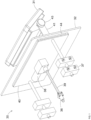
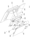
FIG. 1 is a perspective view of an adjustable electronics mounting platform in accordance with an example embodiment utilizing a lead screw drive configuration that is shown from the rear with the platform in an extended position. -
FIG. 2 is a perspective view of the adjustable electronics mounting platform ofFIG. 1 shown from the front in the extended position. -
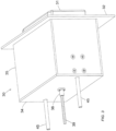
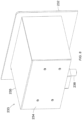
FIG. 3 is a perspective view of the adjustable electronics mounting platform ofFIG. 1 with an enclosure covering certain components thereof with the platform in a stowed/flush position. -
FIG. 4 is a perspective view of an adjustable electronics mounting platform in accordance with another example embodiment using a belt-driven lead screw configuration and shown in an extended position. -
FIG. 5 is a perspective view of the adjustable electronics mounting platform ofFIG. 4 in a stowed/flush position. -
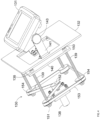
FIG. 6 is a perspective view of an adjustable electronics mounting platform in accordance with still another example embodiment using a scissor-lift drive configuration and shown in an extended position from the front. -
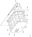
FIG. 7 is a perspective view of the adjustable electronics mounting platform ofFIG. 6 shown in an extended position from the rear. -
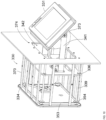
FIG. 8 is a perspective view of the adjustable electronics mounting platform ofFIG. 6 with an enclosure covering certain components thereof. -
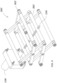
FIG. 9 is a perspective view of an alternative arrangement of a scissor-lift drive configuration which may be used with the mounting platform ofFIG. 6 . -
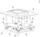
FIG. 10 is a perspective view of an alternative arrangement of the belt-driven mounting platform ofFIG. 4 from the front in an extended position. -
FIG. 11 is a perspective view of the mounting platform ofFIG. 10 from the rear. -
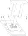
FIG. 12 is a perspective view of a universal (VESA) mount configuration which may be used with different embodiments of the mounting platforms set forth herein. - The present disclosure is provided with reference to the accompanying drawings, in which various embodiments are shown. However, other embodiments in many different forms may be used, and the disclosure should not be construed as limited to the particular embodiments set forth herein. Rather, these embodiments are provided so that this disclosure will be thorough and complete, and will fully convey the claim scope to those skilled in the art. Like numbers refer to like elements throughout, and prime notation is used to indicate similar elements in alternative embodiments.
- Generally speaking, the present disclosure relates to motorized electronic mounting platforms for vehicle consoles, such as for marine electronic units to be mounted on boating consoles. It should be noted, however, that while the following examples are shown and described with gear motor actuators, in some embodiments other actuators may be used, such as a linear actuator, a hand actuator (e.g., hand crank), etc., to achieve a similar function.
- Referring now to
FIGS. 1-3 , in accordance with a first embodiment of the adjustableelectronics mounting platform 30, a lead-screw/rail lift configuration is shown which advantageously provides for lifting of an attachedelectronic device 31 from a flush or stowed position (FIG. 3 ), relative to a front side of aboat console panel 32, to an extended position (FIGS. 1 and2 ) where it is spaced apart from the front side of the boat console panel and can be rotated or pivoted as shown. In the illustrated example, the attachedelectronics unit 31 is a chartplotter, but it will be appreciated by those skilled in the art that the various mounting platforms set forth herein may be used with numerous different types of electronic devices, including chartplotters, sonar/fish finder units, radar units, radios, etc. Moreover, it should be noted that while the mounting platforms described herein are particularly advantageous for marine (boat) applications, they may also be used in other applications as well (aircraft, automobiles, etc.) where electronic devices are to be mounted to a console or dashboard panel. However, for the following examples, a marine (boat) application with a chartplotter installation will be used for convenience of reference. - As seen in
FIG. 3 , in the present example an enclosure or box 33 surrounds themounting platform 30 on the inside/back side of theboat console panel 32. The enclosure 33 illustratively includes abottom 34 and a plurality ofsidewalls 35 extending from the bottom which are connected to the back side of theboat console panel 32 surrounding amounting hole 42 therein. The enclosure 33 advantageously acts as a protective cover and as a mounting frame for thelead screw nut 36 and theguide bushings 37 carried onrails 45 as shown. By way of example, the enclosure 33 may be made of metal, or in some embodiments this could be a plastic (e.g., injection molded) piece that drops into theboat console panel 32 and is attached to the front side of the console panel. - The illustrated lead-screw/rail lift configuration operates as follows. An
electric gear motor 38 rotates alead screw 39 that is threaded through thelead screw nut 36. As themotor 38 rotates, thelead screw 39 exerts a force against the bottom orfloor 34 of the enclosure 33. Themotor 38 is connected to a back side of amounting plate 40, and a pair of adjustable gimbal mounting brackets orarms 41 are connected to a front side of the mounting plate. Thechartplotter 31 is pivotally mounted to thegimbal arms 41 withknobs 43. As thelead screw 39 exerts force against the bottom 34 of the enclosure 33, themount plate 40 and, accordingly, thegimbal arms 41, are then pushed outward, resulting in thechartplotter 31 travelling away from theboat console panel 32 to the extended position. Thegear motor 38 may then be reversed to return thechartplotter 31 to its stowed, flush position. Thegear motor 38 may be actuated by a button or other type of switch, which may be mounted to the console or can be wireless (e.g., on a fob). In some embodiments, the mountingplate 40 may be automatically moved between the flush mount and extended positions, or it may be manually stopped at intermediate positions between the flush mount and extended positions. - The
gimbal arms 41 are attached to the front side of themount plate 40, and thechartplotter 31 is constrained to the gimbal arms usingadjustment knobs 43. The adjustment knobs 43 can be loosened to allow thechartplotter 31 to be rotationally or pivotally adjusted to a desired viewing angle as shown. Thegimbal arms 41 are slotted at their base and are side-to-side adjustable. Thegimbal arms 41 are free to move side-to-side until the screws at their base on the mountingplate 40 are securely tightened. This may advantageously accommodatevarious chartplotters 31 of different widths. Thegimbal arms 41 may also be adjustable along the direction of lift in some embodiments. - As an option, a gasket or seal strips 44, etc., can be used under the console or carried by the mounting
plate 40 so that when the mounting plate is fully lifted the gasket is pressed to form both a water-tight interface and a more solid, stiff mounting surface for thegimbal arms 41. Thechartplotter 31 may also optionally have a seal/gasket under its interface surface to form a seal with the front surface theboat console panel 32 when the chartplotter is in the stowed/flush position. -
FIG. 3 shows the mountingplatform 30 with the enclosure/frame 33 in place.Sidewalls 35 of the enclosure 33 mount to the back side (underside) of theconsole 32 using screws or other suitable attachment device(s). In the illustrated view, thechartplotter 31 is shown in its stowed, flush position. Thelead screw 39 and rails 45 protrude from the bottom 34 of the enclosure 33 in this position. An appropriate clearance may be provided below/behind the enclosure for these components when thechartplotter 31 is stowed position. Moreover, it should also be noted that different sizes of enclosures 33 (as well as other components of the mounting platform 30) may be used to accommodate different sizes ofchartplotters 31, as larger units will need to travel a longer distance between the flush and fully extended positions than smaller units. That is, larger units will need to be further away from the front surface of theboat console panel 32 for pivoting than a smaller unit, as will be appreciated by those skilled in the art. - Turning to
FIGS. 4 and5 , another example embodiment of a belt-driven, four-lead-screwlift mounting platform 130 configuration is now described. As similarly discussed above, the mountingplatform 130 also is configured to lift a chartplotter 131 (or other electronic devices) from a flush position (FIG. 5 ), relative to the front surface of theboat console panel 132, to an extended position (FIG. 4 ) where it can be rotated or pivoted as shown. Although not shown, an enclosure similar to the one shown inFIG. 3 may be used on the back side of the mounting platform 130 (i.e., inside the boat console) to surround the mounting platform. Again, the enclosure would act as a protective cover and as a mounting frame for thegear motor 138,upper bearings 150 andlower bearings 151 carried by thebase 134 of the enclosure. - The belt-driven, four-lead-screw lift configuration operates as follows. The
gear motor 138 rotates apulley 152. Thepulley 152 moves abelt 153 that interfaces with fourother pulleys 154 that are each fastened to arespective lead screw 139. As themotor 138 rotates, the four lead screws rotate in fourlead screw nuts 136 and exert a force on themount plate 140 lifting it or lowering it, depending on direction of rotation of the gear motor.Gimbal arms 141 are attached to themount plate 140, and thechartplotter 131 is constrained to the gimbal arms usingadjustment knobs 143. Once thechartplotter 131 is extended, the adjustment knobs 143 can be loosened to allow the chartplotter to be rotationally adjusted or pivoted to a desired viewing angle as shown. - The
gimbal arms 141 are slotted at their base and are side-to-side adjustable. That is, thegimbal arms 141 are free to move side-to-side until the screws are securely tightened at their base. Again, this accommodatesvarious chartplotter 131 brands or configurations with different shapes and widths. Thegimbal arms 141 may also be adjustable along the direction of lift, if desired. Although not shown, seals or gaskets may be incorporated between the mountingplate 140 and the back of theboat console panel 132, and/or between thechartplotter 131 and the front of the boat console panel as described above, if desired. - Referring now to
FIGS. 6-9 , still another exampleelectronics mounting platform 230 having ascissor lift 260 is now described. Again, the scissorlift mounting platform 230 lifts thechartplotter 231 from a flush position (seeFIG. 7 ), relative to the front surface of theboat console panel 232, to an extended position (seeFIG. 6 ) where it can be rotated or pivoted as shown. Here again, an enclosure 233 (which includes abase 234 and sidewalls 235) may surround the mountingplatform 230 within the console, as shown inFIG. 8 . Theenclosure 233 acts as a protective cover, and thesidewalls 235 act as a mounting frame for thegear motor 238 and thebase 261 andframe members 262 of thescissor lift 260. - The scissor-lift configuration operates as follows. The
gear motor 238 rotates a threaded rod 239 (also known as a lead screw) that is threaded through thecross bar 263 as shown. As themotor 238 rotates, the threadedrod 239 exerts a pulling force on thecross bar 263. Thecross bar 263 is then pulled along aslot 264 on each side of thescissor lift 260, resulting in an expansion of theframe members 262. -
FIG. 7 shows the underside perspective of the scissor lift mechanism 260 (as it would be seen inside the console). Amount plate 240 is attached to theupper frame members 262 of themechanism 260 and is lifted during operation.Gimbal arms 241 are attached to themount plate 240, and thechartplotter 231 is constrained to the gimbal arms usingadjustment knobs 243. The adjustment knobs 243 can be loosened to allow the chartplotter to be rotationally adjusted or pivoted up or down to a desired viewing angle as shown inFIG. 6 . As discussed above, thegimbal arms 241 are side-to-side adjustable, and slotted at the point of attachment to the mount plate. Screws are used to attach thegimbal arms 241 to themount plate 240. Thegimbal arms 241 are free to move side-to-side until the screws are securely tightened. This may advantageously accommodatevarious chartplotter 231 brands or configurations with varying widths. Thegimbal arms 241 may also be adjustable along the direction of lift, if desired, as noted above. - Seal strips 244 (see
FIG. 7 ) or a gasket may optionally be used under the boat console panel 232 (or carried on the mounting plate 240) so that when the mounting plate is fully lifted the seals are compressed to form both a water-tight interface and a more solid, stiff mounting surface for thegimbal arms 241. Seal strips 244 may also be positioned on the front surface of theboat console panel 232 under the interface of the chartplotter 231 (or on the back side of the chartplotter) to form a seal between the boat console panel and chartplotter when the chartplotter is in the stowed/flush position. - The enclosure/
frame 235 mounts to the underside of theboat console panel 232 using screws or other suitable attachment device(s). It should be noted that the location of the threadedrod 239 shown inFIG. 6 allows thegear motor 238 to remain stationary relative to thelift 260. In an alternative embodiment of the scissor lift 260', the threaded rod 239' may be oriented along the direction of travel of the scissor lift. In this case the gear motor 238' would move rather than remain stationary in order to maintain its alignment with the scissor lift mechanism 260'. The threaded rod 239' incorporates both a left-hand and right-hand thread in order to pull together (lifting mode) or push apart (lowering mode) the two cross bars 263' as shown. In such a configuration, the motor 238' may travel in a well-lubricated slide bearing (not shown), which may be mounted to the exterior of the enclosure, for example. - Turning to
FIGS. 10 and11 , an alternative implementation of the belt-drivenmounting platform 130 discussed above is now described. The illustratedmounting platform 330 also is similarly configured to lift a chartplotter 330 (or other electronic devices) from a flush position, relative to the front of the boat console panel 132', to an extended position where it can be rotated or pivoted as shown. A plurality of standoffs or struts 370 connect alower bearing plate 334 to anupper bearing plate 371, which is connected to theboat console panel 332 withscrews 374 and surrounds theopening 342 therein. In some embodiments, an enclosure similar to the one shown inFIG. 3 may be used to cover the mountingplatform 330 within the boat console, if desired. - The present belt-driven, four-lead-screw lift configuration operates as follows. The
gear motor 338 rotates a pulley 352. The pulley 352 moves abelt 353 that interfaces with fourother pulleys 354 that are each fastened to arespective lead screw 339. As thegear motor 338 rotates, the fourlead screws 339 rotate in fourlead screw nuts 336 and exert a force on the mount orlift plate 340 lifting it or lowering it, depending on the direction of rotation of the gear motor.Gimbal arms 341 are attached to the mountingplate 340, and thechartplotter 331 is constrained to the gimbal arms in the example configuration by folding wing screws 373 (although adjustment knobs may also be used in some embodiments as discussed above). Once thechartplotter 331 is extended, the folding wing screws 373 can be loosened to allow the chartplotter to be rotationally adjusted or pivoted to a desired viewing angle as shown. - The
gimbal arms 341 are slotted at their base and are side-to-side adjustable. That is, thegimbal arms 341 are free to move side-to-side until the screws are securely tightened at their base. Again, this accommodates forvarious chartplotter 331 brands or configurations with different shapes and widths. Thegimbal arms 341 may also be adjustable along the direction of lift, if desired. Although not shown, seals or gaskets may be incorporated between the mountingplate 340 and theupper bearing plate 371, and/or between thechartplotter 331 and the front side of theboat console panel 332 as described above, if desired. - In the illustrated example, the
lower bearing plate 334 also illustratively includes anopening 375 for one or more cables, e.g., sonar cables, power cables, network cables (e.g., NMEA 2000), etc., etc. Thelower bearing plate 334 also illustratively includes adrain nozzle 376 for draining any accumulated moisture. Furthermore, the mounting orlift plate 340 also illustratively includes aslot 377 for the cables to pass through to the back of thechartplotter 331. - Referring additionally to
FIG. 12 , a universal orVESA mounting bracket 443 for achartplotter 431 is now described. An articulatingarm 441 is carried by a mounting plate (not shown), similar to the gimbal arms described above. However, thearm 441 terminates in aswivel mount 442 which carries theVESA mounting bracket 443. Other mounts are also possible, such as a ball mount, for example. As will be appreciated by the skilled artisan, theVESA mounting bracket 443 has holes positioned at standardized distances or positions, and the manufacturers of various types of monitors locate corresponding mounting holes at the same positions to provide universal interoperability between different types of monitors and VESA mounts. Generally speaking, with respect to marine electronic devices, smaller units (e.g., less than sixteen inches) typically are configured to be mounted on gimbal arms, whereas larger units (e.g., greater than or equal to sixteen inches (40 cm)) are configured to work with VESA mounts, so the type of bracket to be used in a given installation may advantageously be selected based upon the unit being installed. It should be noted that gimbal and VESA mounts are but two examples of mounts that could be used with the mounting brackets set forth herein, and that other suitable brackets may be used in different embodiments. - Many modifications and other embodiments of the invention will come to the mind of one skilled in the art having the benefit of the teachings presented in the foregoing descriptions and the associated drawings. Therefore, it is understood that the disclosure is not to be limited to the specific embodiments disclosed, and that modifications and embodiments are intended to be included.
Claims (15)
- A mounting system for mounting a marine electronics unit (30) having a screen (31) to a boat console panel (32, 132, 232) and comprising:a base (34, 134) to be connected to the boat console panel and aligned with a mounting hole (42) in the boat console panel;an actuator connected to the base;a mounting plate (40, 140, 240) connected to the actuator; andat least one pivot mount connected to the mounting plate to be connected to the marine electronics unit;wherein the actuator is configured to move the mounting plate between a stowed position where the marine electronics unit is flush with a front side of the boat console panel with the screen viewable at a fixed viewing angle, and an extended position in which the marine electronics unit is spaced apart from the front side of the boat console panel and pivotable using the at least one pivot mount to orient the screen at different viewing angles; anda sealing gasket (44, 244) carried by the mounting plate and configured to seal the mounting plate with a back side of the boat console panel when the mounting plate is in the extended position.
- The mounting system of claim 1 wherein the base comprises an enclosure including a bottom and a plurality of sidewalls extending from the bottom to be connected to a back side of the boat console panel around the mounting hole.
- The mounting system of claim 1 wherein the base comprises a bearing plate (334, 371); and further comprising a plurality of standoffs (370) configured to connect the bearing plate to a back side of the boat console panel around the mounting hole.
- The mounting system of claim 1 wherein the at least one pivot mount comprises a pair of spaced apart gimbal arms (41, 141, 241, 341).
- The mounting system of claim 1 wherein the at least one pivot mount comprises a VESA mount.
- The mounting system of claim 1 wherein the actuator comprises at least one lead screw (39, 139, 339) connected between the base and a lead screw nut (36, 136, 336) carried by the mounting plate, and a motor (38) carried by the base and configured to rotate the at least one lead screw to move the mounting plate between the stowed position and the extended position.
- The mounting system of claim 6 wherein the at least one lead screw comprises a plurality of spaced apart lead screws connected between the base and respective lead screw nuts carried by the mounting plate; further comprising a belt (153, 353) connected between the motor and the lead screws; and wherein the motor is configured to turn the belt to simultaneously rotate the lead screws.
- The mounting system of claim 1 wherein the actuator comprises a scissor lift (260, 260') connected between the base and the mounting plate.
- The mounting system of claim 1 wherein the actuator comprises at least one lead screw connected between the mounting plate and a lead screw nut carried by the base, and a motor carried by the mounting plate and configured to rotate the at least one lead screw to move the mounting plate between the stowed position and the extended position.
- A method for mounting a marine electronics unit (30) having a screen (31) to a boat console panel (32, 132, 232) and comprising:connecting a base (134) of a mounting bracket (443) to the boat console panel and aligned with a mounting hole (42) in the boat console panel, the mounting bracket comprisingan actuator connected to the base,a mounting plate (40, 140, 240) connected to the actuator, andat least one pivot mount connected to the mounting plate; and connecting the marine electronics unit to the at least one pivot mount;wherein the actuator is configured to move the mounting plate between a stowed position where the marine electronics unit is flush with a front side of the boat console panel with the screen viewable at a fixed viewing angle, and an extended position in which the marine electronics unit is spaced apart from the front side of the boat console panel and pivotable using the at least one pivot mount to orient the screen at different viewing angles, wherein the mounting bracket further comprises a sealing gasket (44, 244) carried by the mounting plate and configured to seal the mounting plate with a back side of the boat console panel when the mounting plate is in the extended position.
- The method of claim 10 wherein the base comprises a box (33, 233) including a bottom (34, 234) and a plurality of sidewalls (35, 235) extending from the bottom; and wherein connecting the base comprises connecting the sidewalls to a back side of the boat console panel around the mounting hole.
- The method of claim 10 wherein the base comprises a bearing plate (334, 371); and wherein connecting the base comprises connecting the bearing plate to a back side of the boat console panel around the mounting hole using a plurality of standoffs (370).
- The method of claim 10 wherein the at least one pivot mount comprises a pair of spaced apart gimbal arms (41, 141, 241, 341).
- The method of claim 10 wherein the at least one pivot mount comprises a VESA mount.
- The method of claim 10 wherein the actuator comprises at least one lead screw (39, 139, 339) connected between the base and a lead screw nut (36, 136, 336) carried by the mounting plate, and a motor (38) carried by the base and configured to rotate the at least one lead screw to move the mounting plate between the stowed position and the extended position.
Applications Claiming Priority (2)
| Application Number | Priority Date | Filing Date | Title |
|---|---|---|---|
| US201962891478P | 2019-08-26 | 2019-08-26 | |
| PCT/US2020/047907 WO2021041483A1 (en) | 2019-08-26 | 2020-08-26 | Adjustable electronics mounting platform and related methods |
Publications (4)
| Publication Number | Publication Date |
|---|---|
| EP4021797A1 EP4021797A1 (en) | 2022-07-06 |
| EP4021797A4 EP4021797A4 (en) | 2023-10-18 |
| EP4021797B1 true EP4021797B1 (en) | 2025-06-25 |
| EP4021797C0 EP4021797C0 (en) | 2025-06-25 |
Family
ID=74681572
Family Applications (1)
| Application Number | Title | Priority Date | Filing Date |
|---|---|---|---|
| EP20857148.9A Active EP4021797B1 (en) | 2019-08-26 | 2020-08-26 | Adjustable electronics mounting platform and related methods |
Country Status (6)
| Country | Link |
|---|---|
| US (2) | US11447215B2 (en) |
| EP (1) | EP4021797B1 (en) |
| AU (1) | AU2020337913B2 (en) |
| CA (1) | CA3152724C (en) |
| ES (1) | ES3042105T3 (en) |
| WO (1) | WO2021041483A1 (en) |
Families Citing this family (5)
| Publication number | Priority date | Publication date | Assignee | Title |
|---|---|---|---|---|
| WO2021041483A1 (en) * | 2019-08-26 | 2021-03-04 | Isla Mapping Llc | Adjustable electronics mounting platform and related methods |
| CN112977749A (en) * | 2021-02-26 | 2021-06-18 | 滨州职业学院 | Wall-mounted navigation operation equipment for landing ship |
| CN116872854A (en) * | 2023-08-08 | 2023-10-13 | 长广溪智能制造(无锡)有限公司 | A linear motion mechanism and vehicle-mounted screen |
| US12320469B1 (en) | 2023-08-11 | 2025-06-03 | Rose Metal Products, Inc. | Electronic device platform |
| CN117162930A (en) * | 2023-08-30 | 2023-12-05 | 长广溪智能制造(无锡)有限公司 | Vehicle display position adjustment device, vehicle display and vehicle |
Family Cites Families (29)
| Publication number | Priority date | Publication date | Assignee | Title |
|---|---|---|---|---|
| US5865403A (en) * | 1995-09-18 | 1999-02-02 | Lowrance Electronics, Inc. | Mounting bracket for dash mountable marine electronics |
| JP2851267B2 (en) | 1996-08-09 | 1999-01-27 | パーク クワン−スー | Automatic lifting device for computer monitor box |
| US6179253B1 (en) | 1998-02-10 | 2001-01-30 | R. Gene Cotton | Marine instrument display mount |
| JP3887133B2 (en) | 1999-09-10 | 2007-02-28 | パイオニア株式会社 | Display device |
| US20020101139A1 (en) * | 2001-01-30 | 2002-08-01 | Lee Tsai Ming | Elevating device for planer displayer |
| US20050001105A1 (en) * | 2001-10-30 | 2005-01-06 | Akihiro Matsuda | Vehicle-mounted electronic device |
| GB2392882A (en) * | 2002-09-12 | 2004-03-17 | Sealine Internat Ltd | A boat having a concealed display device |
| US6733094B1 (en) * | 2002-11-13 | 2004-05-11 | Chun-Chung Chang | Lifting device for LCD |
| US6902243B2 (en) | 2003-02-25 | 2005-06-07 | Wieslaw Bober | Modular sub-cabinet for motion furniture |
| CH696885A5 (en) * | 2004-04-14 | 2008-01-15 | Art Over Tv Ag | Device of a movable wall paneling for concealing or highlighting a background. |
| US20060076860A1 (en) * | 2004-04-14 | 2006-04-13 | Daniel Hoss | Device and method for covering and exposing an object |
| KR100638901B1 (en) * | 2004-12-14 | 2006-10-26 | 엘지전자 주식회사 | Tilting assembly of display |
| US20060180403A1 (en) | 2005-01-07 | 2006-08-17 | Hanlon Mark T | Screw scissor lift |
| JP4389845B2 (en) * | 2005-06-15 | 2009-12-24 | 株式会社デンソー | In-vehicle device |
| KR100779252B1 (en) * | 2006-01-23 | 2007-11-27 | 코스텔(주) | Flush display device |
| WO2007062214A2 (en) * | 2005-11-21 | 2007-05-31 | Clo Systems, Llc | Motorized mount system for repositioning a monitor |
| KR100801251B1 (en) * | 2006-04-13 | 2008-02-04 | 삼성전기주식회사 | Display extension device |
| US7959226B2 (en) * | 2007-07-03 | 2011-06-14 | Toyota Boshoku Kabushiki Kaisha | Vehicle seats |
| KR101083588B1 (en) | 2008-11-17 | 2011-11-16 | 노틸러스효성 주식회사 | Financial Automation Equipment for Vehicle Drivers |
| US8434272B2 (en) * | 2010-01-29 | 2013-05-07 | Edward F. MARTINEZ | Weatherproofing assembly for use with a slide-out compartment of recreational vehicle |
| US8430051B1 (en) | 2010-12-15 | 2013-04-30 | Darris E. Allison | Electronics pedestal for boats |
| CN102697288B (en) * | 2012-06-07 | 2014-10-22 | 集美大学 | Multifunctional desk |
| US9481403B1 (en) * | 2015-06-25 | 2016-11-01 | Robert Johnson | Secure truck box system |
| US10293900B1 (en) | 2016-01-29 | 2019-05-21 | Timothy Mark Leonard | Height adjustable depth finder apparatus and system |
| CN206486239U (en) | 2016-11-16 | 2017-09-12 | 李国城 | A kind of intelligent automation accurately controls lowering or hoisting gear |
| CN106617688B (en) | 2016-11-22 | 2020-04-21 | 杭州华会通科技股份有限公司 | Highly intelligent lifter |
| CN207380609U (en) | 2017-10-27 | 2018-05-18 | 曾晓峰 | Rotary computer display |
| US10625688B2 (en) * | 2017-11-06 | 2020-04-21 | Global Ip Holdings, Llc | Assembly capable of deploying an electronic device having a display screen in a vehicle |
| WO2021041483A1 (en) * | 2019-08-26 | 2021-03-04 | Isla Mapping Llc | Adjustable electronics mounting platform and related methods |
-
2020
- 2020-08-26 WO PCT/US2020/047907 patent/WO2021041483A1/en not_active Ceased
- 2020-08-26 AU AU2020337913A patent/AU2020337913B2/en active Active
- 2020-08-26 US US17/002,932 patent/US11447215B2/en active Active
- 2020-08-26 EP EP20857148.9A patent/EP4021797B1/en active Active
- 2020-08-26 ES ES20857148T patent/ES3042105T3/en active Active
- 2020-08-26 CA CA3152724A patent/CA3152724C/en active Active
-
2022
- 2022-09-19 US US17/933,221 patent/US12565294B2/en active Active
Also Published As
| Publication number | Publication date |
|---|---|
| EP4021797A1 (en) | 2022-07-06 |
| AU2020337913B2 (en) | 2023-11-16 |
| US12565294B2 (en) | 2026-03-03 |
| CA3152724A1 (en) | 2021-03-04 |
| CA3152724C (en) | 2023-09-12 |
| AU2020337913A1 (en) | 2022-03-31 |
| WO2021041483A1 (en) | 2021-03-04 |
| US20230011455A1 (en) | 2023-01-12 |
| US11447215B2 (en) | 2022-09-20 |
| EP4021797A4 (en) | 2023-10-18 |
| US20210061425A1 (en) | 2021-03-04 |
| ES3042105T3 (en) | 2025-11-18 |
| EP4021797C0 (en) | 2025-06-25 |
Similar Documents
| Publication | Publication Date | Title |
|---|---|---|
| US12565294B2 (en) | Adjustable electronics mounting platform and related methods | |
| US6386413B1 (en) | Apparatus and method for mounting a computer system in a vehicle | |
| US4235405A (en) | Support apparatus for a camera | |
| US20250263023A1 (en) | Surveillance platform having a retractable telescoping structure that fully retracts within a vehicle and which has surveillance equipment mounted thereon, and sealing device mounted to the telescoping structure | |
| US12449521B2 (en) | Forward facing sonar and mount | |
| US20120261520A1 (en) | Articulating yoke mount | |
| US11827134B2 (en) | Table device for a vehicle, and vehicle | |
| CN106654512B (en) | A kind of wall-mounted digital television receiver antenna | |
| CA2438489A1 (en) | Retractable vehicle step | |
| US20060181099A1 (en) | Motorized rack and pinion assembly | |
| US20030107526A1 (en) | Satellite dish for trucks | |
| US6267071B1 (en) | Adjustable helm seat and actuating apparatus of same | |
| CN107154525B (en) | A kind of suspension type digital television receiver antenna | |
| EP1621404A1 (en) | Motorized rack and pinion assembly | |
| US20230140140A1 (en) | Boat wind and spray protection device | |
| GB2579542A (en) | Vehicle seat support assembly | |
| EP0522315A1 (en) | A lifting and positioning structure for an aerial platform, particularly for use in elevating machines | |
| CN119262216A (en) | A remote controlled tail radar scanner rotating base device | |
| CN212149237U (en) | Marine operation panel based on tug driver's cabin | |
| US20060267327A1 (en) | Apparatus for attachment of a camera to a vehicle | |
| CN115218092A (en) | Adjusting device of vehicle-mounted screen, vehicle-mounted display device and vehicle | |
| KR200141938Y1 (en) | Outside mirror | |
| CA3118532A1 (en) | Adjustable mirror assembly for a work machine | |
| JPH0885386A (en) | Vehicle monitoring device | |
| JPH11192995A (en) | Underwater towed cable deployment sensor deployer |
Legal Events
| Date | Code | Title | Description |
|---|---|---|---|
| STAA | Information on the status of an ep patent application or granted ep patent |
Free format text: STATUS: THE INTERNATIONAL PUBLICATION HAS BEEN MADE |
|
| PUAI | Public reference made under article 153(3) epc to a published international application that has entered the european phase |
Free format text: ORIGINAL CODE: 0009012 |
|
| STAA | Information on the status of an ep patent application or granted ep patent |
Free format text: STATUS: REQUEST FOR EXAMINATION WAS MADE |
|
| 17P | Request for examination filed |
Effective date: 20220318 |
|
| AK | Designated contracting states |
Kind code of ref document: A1 Designated state(s): AL AT BE BG CH CY CZ DE DK EE ES FI FR GB GR HR HU IE IS IT LI LT LU LV MC MK MT NL NO PL PT RO RS SE SI SK SM TR |
|
| DAV | Request for validation of the european patent (deleted) | ||
| DAX | Request for extension of the european patent (deleted) | ||
| A4 | Supplementary search report drawn up and despatched |
Effective date: 20230915 |
|
| RIC1 | Information provided on ipc code assigned before grant |
Ipc: B60R 11/00 20060101ALN20230911BHEP Ipc: F16M 11/24 20060101ALI20230911BHEP Ipc: F16M 11/38 20060101ALI20230911BHEP Ipc: F16M 11/18 20060101ALI20230911BHEP Ipc: F16M 13/02 20060101ALI20230911BHEP Ipc: F16M 11/10 20060101ALI20230911BHEP Ipc: B60R 11/02 20060101ALI20230911BHEP Ipc: F16M 11/04 20060101ALI20230911BHEP Ipc: B63B 49/00 20060101AFI20230911BHEP |
|
| STAA | Information on the status of an ep patent application or granted ep patent |
Free format text: STATUS: EXAMINATION IS IN PROGRESS |
|
| 17Q | First examination report despatched |
Effective date: 20240507 |
|
| GRAP | Despatch of communication of intention to grant a patent |
Free format text: ORIGINAL CODE: EPIDOSNIGR1 |
|
| STAA | Information on the status of an ep patent application or granted ep patent |
Free format text: STATUS: GRANT OF PATENT IS INTENDED |
|
| RIC1 | Information provided on ipc code assigned before grant |
Ipc: B60R 11/00 20060101ALN20250131BHEP Ipc: F16M 11/24 20060101ALI20250131BHEP Ipc: F16M 11/38 20060101ALI20250131BHEP Ipc: F16M 11/18 20060101ALI20250131BHEP Ipc: F16M 13/02 20060101ALI20250131BHEP Ipc: F16M 11/10 20060101ALI20250131BHEP Ipc: B60R 11/02 20060101ALI20250131BHEP Ipc: F16M 11/04 20060101ALI20250131BHEP Ipc: B63B 49/00 20060101AFI20250131BHEP |
|
| INTG | Intention to grant announced |
Effective date: 20250217 |
|
| RIN1 | Information on inventor provided before grant (corrected) |
Inventor name: WOLFE, CHRISTOPHER, D. Inventor name: HOUSMAN, GLENN, D. |
|
| GRAS | Grant fee paid |
Free format text: ORIGINAL CODE: EPIDOSNIGR3 |
|
| GRAA | (expected) grant |
Free format text: ORIGINAL CODE: 0009210 |
|
| STAA | Information on the status of an ep patent application or granted ep patent |
Free format text: STATUS: THE PATENT HAS BEEN GRANTED |
|
| AK | Designated contracting states |
Kind code of ref document: B1 Designated state(s): AL AT BE BG CH CY CZ DE DK EE ES FI FR GB GR HR HU IE IS IT LI LT LU LV MC MK MT NL NO PL PT RO RS SE SI SK SM TR |
|
| REG | Reference to a national code |
Ref country code: GB Ref legal event code: FG4D |
|
| REG | Reference to a national code |
Ref country code: CH Ref legal event code: EP |
|
| REG | Reference to a national code |
Ref country code: CH Ref legal event code: EP |
|
| REG | Reference to a national code |
Ref country code: IE Ref legal event code: FG4D |
|
| U01 | Request for unitary effect filed |
Effective date: 20250701 |
|
| U07 | Unitary effect registered |
Designated state(s): AT BE BG DE DK EE FI FR IT LT LU LV MT NL PT RO SE SI Effective date: 20250707 |
|
| U20 | Renewal fee for the european patent with unitary effect paid |
Year of fee payment: 6 Effective date: 20250703 |
|
| PGFP | Annual fee paid to national office [announced via postgrant information from national office to epo] |
Ref country code: ES Payment date: 20250901 Year of fee payment: 6 |
|
| PGFP | Annual fee paid to national office [announced via postgrant information from national office to epo] |
Ref country code: NO Payment date: 20250820 Year of fee payment: 6 Ref country code: GR Payment date: 20250925 Year of fee payment: 6 |
|
| PGFP | Annual fee paid to national office [announced via postgrant information from national office to epo] |
Ref country code: GB Payment date: 20250708 Year of fee payment: 6 |
|
| PG25 | Lapsed in a contracting state [announced via postgrant information from national office to epo] |
Ref country code: HR Free format text: LAPSE BECAUSE OF FAILURE TO SUBMIT A TRANSLATION OF THE DESCRIPTION OR TO PAY THE FEE WITHIN THE PRESCRIBED TIME-LIMIT Effective date: 20250625 |
|
| PG25 | Lapsed in a contracting state [announced via postgrant information from national office to epo] |
Ref country code: RS Free format text: LAPSE BECAUSE OF FAILURE TO SUBMIT A TRANSLATION OF THE DESCRIPTION OR TO PAY THE FEE WITHIN THE PRESCRIBED TIME-LIMIT Effective date: 20250925 |
|
| REG | Reference to a national code |
Ref country code: GR Ref legal event code: EP Ref document number: 20250401899 Country of ref document: GR Effective date: 20251009 |
|
| REG | Reference to a national code |
Ref country code: ES Ref legal event code: FG2A Ref document number: 3042105 Country of ref document: ES Kind code of ref document: T3 Effective date: 20251118 |
|
| PG25 | Lapsed in a contracting state [announced via postgrant information from national office to epo] |
Ref country code: IS Free format text: LAPSE BECAUSE OF FAILURE TO SUBMIT A TRANSLATION OF THE DESCRIPTION OR TO PAY THE FEE WITHIN THE PRESCRIBED TIME-LIMIT Effective date: 20251025 |
|
| PG25 | Lapsed in a contracting state [announced via postgrant information from national office to epo] |
Ref country code: SM Free format text: LAPSE BECAUSE OF FAILURE TO SUBMIT A TRANSLATION OF THE DESCRIPTION OR TO PAY THE FEE WITHIN THE PRESCRIBED TIME-LIMIT Effective date: 20250625 |
|
| PG25 | Lapsed in a contracting state [announced via postgrant information from national office to epo] |
Ref country code: CZ Free format text: LAPSE BECAUSE OF FAILURE TO SUBMIT A TRANSLATION OF THE DESCRIPTION OR TO PAY THE FEE WITHIN THE PRESCRIBED TIME-LIMIT Effective date: 20250625 |
|
| PG25 | Lapsed in a contracting state [announced via postgrant information from national office to epo] |
Ref country code: PL Free format text: LAPSE BECAUSE OF FAILURE TO SUBMIT A TRANSLATION OF THE DESCRIPTION OR TO PAY THE FEE WITHIN THE PRESCRIBED TIME-LIMIT Effective date: 20250625 |
|
| PG25 | Lapsed in a contracting state [announced via postgrant information from national office to epo] |
Ref country code: SK Free format text: LAPSE BECAUSE OF FAILURE TO SUBMIT A TRANSLATION OF THE DESCRIPTION OR TO PAY THE FEE WITHIN THE PRESCRIBED TIME-LIMIT Effective date: 20250625 |
|
| REG | Reference to a national code |
Ref country code: CH Ref legal event code: H13 Free format text: ST27 STATUS EVENT CODE: U-0-0-H10-H13 (AS PROVIDED BY THE NATIONAL OFFICE) Effective date: 20260324 |
|
| PG25 | Lapsed in a contracting state [announced via postgrant information from national office to epo] |
Ref country code: MC Free format text: LAPSE BECAUSE OF FAILURE TO SUBMIT A TRANSLATION OF THE DESCRIPTION OR TO PAY THE FEE WITHIN THE PRESCRIBED TIME-LIMIT Effective date: 20250625 |
|
| PG25 | Lapsed in a contracting state [announced via postgrant information from national office to epo] |
Ref country code: CH Free format text: LAPSE BECAUSE OF NON-PAYMENT OF DUE FEES Effective date: 20250831 |
|
| PLBE | No opposition filed within time limit |
Free format text: ORIGINAL CODE: 0009261 |
|
| STAA | Information on the status of an ep patent application or granted ep patent |
Free format text: STATUS: NO OPPOSITION FILED WITHIN TIME LIMIT |
|
| REG | Reference to a national code |
Ref country code: CH Ref legal event code: L10 Free format text: ST27 STATUS EVENT CODE: U-0-0-L10-L00 (AS PROVIDED BY THE NATIONAL OFFICE) Effective date: 20260507 |