EP4021789B1 - A bicycle comprising a torque support device - Google Patents
A bicycle comprising a torque support device Download PDFInfo
- Publication number
- EP4021789B1 EP4021789B1 EP21704626.7A EP21704626A EP4021789B1 EP 4021789 B1 EP4021789 B1 EP 4021789B1 EP 21704626 A EP21704626 A EP 21704626A EP 4021789 B1 EP4021789 B1 EP 4021789B1
- Authority
- EP
- European Patent Office
- Prior art keywords
- axle
- frame
- bicycle
- support device
- torque
- Prior art date
- Legal status (The legal status is an assumption and is not a legal conclusion. Google has not performed a legal analysis and makes no representation as to the accuracy of the status listed.)
- Active
Links
Images


Classifications
-
- B—PERFORMING OPERATIONS; TRANSPORTING
- B62—LAND VEHICLES FOR TRAVELLING OTHERWISE THAN ON RAILS
- B62K—CYCLES; CYCLE FRAMES; CYCLE STEERING DEVICES; RIDER-OPERATED TERMINAL CONTROLS SPECIALLY ADAPTED FOR CYCLES; CYCLE AXLE SUSPENSIONS; CYCLE SIDECARS, FORECARS, OR THE LIKE
- B62K25/00—Axle suspensions
- B62K25/02—Axle suspensions for mounting axles rigidly on cycle frame or fork, e.g. adjustably
-
- B—PERFORMING OPERATIONS; TRANSPORTING
- B60—VEHICLES IN GENERAL
- B60B—VEHICLE WHEELS; CASTORS; AXLES FOR WHEELS OR CASTORS; INCREASING WHEEL ADHESION
- B60B27/00—Hubs
- B60B27/02—Hubs adapted to be rotatably arranged on axle
- B60B27/023—Hubs adapted to be rotatably arranged on axle specially adapted for bicycles
- B60B27/026—Hubs adapted to be rotatably arranged on axle specially adapted for bicycles comprising quick release devices
-
- B—PERFORMING OPERATIONS; TRANSPORTING
- B60—VEHICLES IN GENERAL
- B60B—VEHICLE WHEELS; CASTORS; AXLES FOR WHEELS OR CASTORS; INCREASING WHEEL ADHESION
- B60B35/00—Axle units; Parts thereof ; Arrangements for lubrication of axles
- B60B35/004—Mounting arrangements for axles
- B60B35/006—Mounting arrangements for axles with mounting plates or consoles fitted to axles
-
- B—PERFORMING OPERATIONS; TRANSPORTING
- B62—LAND VEHICLES FOR TRAVELLING OTHERWISE THAN ON RAILS
- B62M—RIDER PROPULSION OF WHEELED VEHICLES OR SLEDGES; POWERED PROPULSION OF SLEDGES OR SINGLE-TRACK CYCLES; TRANSMISSIONS SPECIALLY ADAPTED FOR SUCH VEHICLES
- B62M9/00—Transmissions characterised by use of an endless chain, belt, or the like
- B62M9/04—Transmissions characterised by use of an endless chain, belt, or the like of changeable ratio
- B62M9/06—Transmissions characterised by use of an endless chain, belt, or the like of changeable ratio using a single chain, belt, or the like
- B62M9/10—Transmissions characterised by use of an endless chain, belt, or the like of changeable ratio using a single chain, belt, or the like involving different-sized wheels, e.g. rear sprocket chain wheels selectively engaged by the chain, belt, or the like
- B62M9/12—Transmissions characterised by use of an endless chain, belt, or the like of changeable ratio using a single chain, belt, or the like involving different-sized wheels, e.g. rear sprocket chain wheels selectively engaged by the chain, belt, or the like the chain, belt, or the like being laterally shiftable, e.g. using a rear derailleur
- B62M9/121—Rear derailleurs
- B62M9/125—Mounting the derailleur on the frame
-
- B—PERFORMING OPERATIONS; TRANSPORTING
- B60—VEHICLES IN GENERAL
- B60Y—INDEXING SCHEME RELATING TO ASPECTS CROSS-CUTTING VEHICLE TECHNOLOGY
- B60Y2200/00—Type of vehicle
- B60Y2200/10—Road Vehicles
- B60Y2200/13—Bicycles; Tricycles
-
- B—PERFORMING OPERATIONS; TRANSPORTING
- B62—LAND VEHICLES FOR TRAVELLING OTHERWISE THAN ON RAILS
- B62K—CYCLES; CYCLE FRAMES; CYCLE STEERING DEVICES; RIDER-OPERATED TERMINAL CONTROLS SPECIALLY ADAPTED FOR CYCLES; CYCLE AXLE SUSPENSIONS; CYCLE SIDECARS, FORECARS, OR THE LIKE
- B62K25/00—Axle suspensions
- B62K25/02—Axle suspensions for mounting axles rigidly on cycle frame or fork, e.g. adjustably
- B62K2025/025—Hinged axle clamps
Definitions
- the invention concerns a bicycle comprising torque support device, for supporting a torque of a hollow shaft onto a frame of the bicycle.
- a Flat Mount is a disc brake mounting system and an open standard for sport bicycles.
- FMBA Flat Mount Brake Assembly
- the mounting surface for a brake caliper is normally fixed within +/- 0.15 mm in height.
- the height of mounting surfaces can be chosen at the discretion of the frame builder, but is generally between 10 - 35 mm, wherein between frames differences between 10 - 35 mm can be observed quantified in steps of 5 mm.
- switching gears may occur via a fixed transmission to a shaft of a rear wheel axle, or by engaging the shaft of a rear wheel axle.
- Braking generally occurs by means of a caliper that engages a braking rotor that is supported on the shaft of the axle.
- a rear wheel in particular, the fitting of a replacement wheel may be hindered by alignment issues, such as may arise when the braking caliper and braking rotor are misaligned.
- the person replacing the wheel would have to insert the wheel just right in order to avoid such a misalignment.
- US2013/0241175 A1 discloses a bicycle with a dropout defining a recess and a torque element that is secured to a first end of an axle and is shaped to fit within the recess of the dropout to inhibit rotation of the axle relative to the frame in response to torque from a motor.
- Document JP H08 337191 A is considered as the closest prior art for claim 1 and discloses a bicycle comprising: a frame having a dropout; and an axle assembly comprising a hollow shaft (20), a thru-axle (5) and a wheel hub; the axle assembly comprising a torque support device (30), for supporting the torque of the hollow shaft onto the frame of the bicycle, comprising: a cam hole (31) receiving therein a distal end of the shaft, wherein the cam hole and the shaft are interlockingly shaped for rotationally locking the torque support device and shaft with respect to each other; a through hole extending, coaxially with respect to the cam hole, through the torque support device allowing the thru-axle to extend therethrough; a first face for facing the hollow shaft, and a second face facing a dropout recess of the dropout, wherein a boss (34) is extending from the second face; and a base extending from a remainder of the torque support device in a direction transverse to the direction in which the through hole extends, the
- a bicycle comprising a torque support device according to claim 1.
- the device allows for mounting the hollow shaft to the frame, e.g. between the drop outs, such that torque can be transferred from the hollow shaft to the frame, via the device.
- the hollow shaft can be prevented from rotating relative to the frame while transferring torque to the frame. Nevertheless, easy mounting and dismounting of the hollow shaft relative to the frame is still possible.
- the device comprises a through hole.
- the cam hole is an at least partially blind hole.
- the device is arranged for supporting at least some torque forces onto the frame via the through hole of the dropout recess of the frame.
- the device is arranged for supporting at least some torque forces onto the frame via the brake caliper connection of the frame.
- the device is arranged to refrain from supporting torque to the dropout.
- the device can be arranged to refrain from supporting torque to the dropout recess edge. Then for instance the torque can be supported onto the frame outside the dropout recess, such as outside the dropout, e.g. at the brake caliper connection of the frame.
- the device is arranged for supporting at least some torque forces onto the frame via the thru-axle.
- the device comprises a base which, in use, i.e. when mounted to the frame, extends into a length direction of the frame, wherein the base comprises at least one screw seat, for fastening the device there through onto a brake caliper connection of the frame, such that the through hole is aligned with the through hole in the drop out.
- the through hole is aligned with a resting position of the thru-axle in the drop out recess.
- the brake caliper connection may be a screw connection, such as with an M5 bolt.
- the device may comprise a fixable angularly adjustable connection for adjusting an angle with which the device is fixed to the frame.
- the angle can be adjustable to allow the device through hole to be aligned with a through hole or rounded end of a shaft mounting slot in the drop out. Alternatively, or additionally, the angle can be adjustable.
- a rear axle assembly comprising a torque support device according to any of the preceding claims, a wheel hub, and a sprocket or a plurality of sprockets rotatably mounted to the hollow shaft.
- the hub is rotatably mounted to the hollow shaft and the sprocket(s) are arranged for driving the hub in rotation.
- the rear axle assembly comprises a transmission between the sprocket or plurality or sprockets and the wheel hub shaft.
- the transmission comprises at least two selectable drives between the sprocket(s) and the hub.
- additional gear ratios can be provided.
- the transmission can include a planetary gear set having a first, second and third rotational body.
- the first rotational body can be a ring gear
- the second rotational body can be a planet carrier
- the third rotational body can be a sun gear.
- the ring gear can be connected to the sprocket(s) and the planet carrier can be connected to the hub.
- the ring gear can be connected to the hub and the planet carrier can be connected to the sprocket(s).
- the transmission In a first mode the ring gear and the planet carrier are rotationally fixed relative to each other, the transmission operates according to a first gear ratio (such as unity).
- the sun gear may in that case freewheel relative to the hollow shaft.
- the ring gear and the planet carrier In a second mode, the ring gear and the planet carrier are not rotationally fixed relative to each other, and the sun gear transfers torque to the hollow shaft, such that the transmission operates according to a second gear ratio (such as 0.5-0.9, e.g. about 0.7).
- a second gear ratio such as 0.5-0.9, e.g. about 0.7.
- the transmission can be arranged to transfer torque to the hollow shaft.
- the transfer of torque requires a proper of transfer of torque from the hollow shaft to the frame, which can be achieved through the device.
- the transfer of torque from the hollow shaft to the device results in a support force on the device and a reaction force.
- This reaction force can hereby be supported on the frame.
- the device may be arranged for supporting the torque onto the frame via a screw connection, such as via washers, in particular spherical or conical washers.
- Spherical washers come in sets having a first washer with a concave side and a second washer with a matching convex side. This allows the torque force to be supported e.g. on the the brake mount via the device.
- the device comprises a boss arranged for resting in the dropout recess. This allows the nesting of the device in the drop out recess.
- the device may be a monolithic element.
- the device may be made of one of stainless steel, aluminum, aluminum alloy, titanium, and titanium alloy. However, other materials can be contemplated, such as engineering plastics, surface treated steel, or the like.
- the device is made of a combination of reinforced plastic and a metal, such as stainless steel, aluminum, or an alloy.
- the cam hole may comprise spline teeth for interlocking with spline teeth on an outer surface of the shaft.
- the device is arranged for being clamped to the frame by the thru-axle.
- the device is arranged for being clamped to the frame via a clamping end of the thru-axle.
- the device can be designed to have an installation height of 20 - 30 mm, such as 25 mm.
- the at least two selectable drives of the transmission can be selected by an electrically actuatable actuator.
- the electrically actuatable actuator can be arranged on the wheel axle.
- a rider operable shift control unit e.g. mounted at the handlebars or frame of the bicycle, can be used for generating a shift signal.
- the actuator can be controlled on the basis of the shift signal.
- the actuator can include an electrical component arranged on the wheel axle which is configured to be controlled by the shift signal.
- the device holds a wired or wireless receiver, and/or an antenna therefor, for receiving the shift signal.
- the wired or wireless receiver can be arranged for receiving the shift signal from the rider operable shift control unit.
- the device can include an electrical power storage, such as a battery. The power storage can be connected to the wired or wireless receiver.
- an electrical connection is arranged between the device, the thru-axle and/or the wheel axle.
- the shift control signal or a signal associated with the shift control signal, can be communicated from the device, e.g. from the wired or wireless receiver, to the actuator on the wheel axle, e.g. via the thru-axle and the wheel axle.
- a detachable electric connection is provided between the device and the actuator.
- the detachable electric connection can be provided between the wired or wireless receiver and the actuator
- electric power and/or information is provided to the electric component in or attached to the wheel axle via a contact or contactless electric coupling.
- the device is used for providing the contact or contactless electric coupling between the electric component in or attached to the wheel axle and the power supply and/or control element.
- the device is provided with a first transmitter for transmitting electric power and/or signals to the wheel axle.
- the wheel axle can be provided with a first receiver for receiving electric power and/or the signals from the first transmitter.
- the device can be provided with a first coil as part of the first transmitter and the wheel axle can be provided with a second coil as part of the first receiver.
- the first and second coils can be sealed against debris and/or water.
- the first and second coils are positioned such that when the wheel axle is in the position for securing the wheel in the frame, the first and second coils are axially positioned relative to each other such that a coupling can be achieved at high efficiency, e.g. at maximum efficiency.
- the coils will be coupled inductively.
- the inductively coupled coils are able to transmit electric power and/or electric signals from one coil to the other, the coupling between the coils is herein also referred to as electric coupling.
- the first transmitter is wiredly or wirelessly connected to the control element.
- a middle frequency resonance of the signal on the order of 100 kHz can be used over the coils.
- the system is arranged for transferring both power and signal between the coils, in one direction or in both directions.
- the thru-axle is provided with the first transmitter for transmitting electric power and/or signals to the wheel axle.
- the thru-axle can be provided with a first coil as part of the first transmitter.
- the first transmitter of the thru-axle can be connected to the receiver in the cam or the adapter, e.g. via a wired electrical connection.
- the device includes an actuator controller arranged for controlling the actuator.
- directing a driving signal to the actuator may suffice.
- the driving signal can e.g. be a positive or a negative dc current for driving the actuator for up-shift or down-shift, respectively, or vice versa.
- a first energy storage element such as a battery
- a second energy storage element such as a battery
- the first energy storage element can be arranged for providing the first coil with energy.
- the second energy storage element can be arranged for providing the second coil with energy.
- the first energy storage element has a storage capacity that is at least ten (10) times the storage capacity of the second energy storage element.
- the system is arranged for charging the second energy storage element using energy stored in the first energy storage element.
- the second energy storage element can be maintained in a state of sufficient charge.
- energy can be transferred from the first energy storage element to the second energy storage element via the first and second coils.
- the system can be arranged for providing energy to an actuator and/or sensor included in or attached to the wheel axle from the second energy storage element.
- the system can be arranged for providing energy to an actuator and/or sensor included in or attached to the wheel axle from the first energy storage element. This can also be done via the electrical contacts.
- the system can be arranged for transferring a signal determining an actuation direction and/or amount for the actuator included in or attached to the wheel axle via the first and second coils, or via the electrical contacts.
- the system can be arranged for transferring a signal from the control element (e.g. on the handlebars) to the device and/or thru axle. Signal transfer from the control element (e.g. on the handlebars) to the device and/or thru-axle can be wireless.
- a second wireless receiver or transceiver can be included in or attached to the device and/or thru-axle.
- the second transceiver or receiver is herein further referred to as second receiver, nevertheless still covering the possibility of it being a transceiver.
- the second wireless receiver can be mounted to the device so as to extend outside the wheel axle to reduce disturbance of wireless communication by metal parts of the wheel axle and/or frame.
- the system can be arranged for providing the second receiver with electric power from the first energy storage element.
- the device and/or thru-axle can remain with the frame so that a pairing between the control element and the second receiver in/on the device and/or thru-axle can be maintained. Therefore, when exchanging the wheel no time is lost on pairing the control element with the replacement wheel.
- the pairing of the control element, e.g. of a wireless transmitter of the control element, with the second receiver in/on the device and/or thru-axle can be performed, e.g. once when matching the device and/or thru-axle with the frame.
- the second energy storage element can be charged from the first energy storage element. Since the first energy storage element is included in or attached to the device and/or thru-axle, it can easily be charged e.g. via a connector on the device and/or thru-axle. Charging can be performed while leaving the device and/or thru-axle in the bicycle or with the device and/or thru-axle removed from the bicycle.
- the first coil can be used for charging the first energy storage element, e.g. via an external charger, e.g. including a third coil.
- the system can be arranged such that the first energy storage element automatically charges the second energy storage element so that the second energy storage element can always provide the actuator with electric power. In this way also the user never needs to charge or replace the second energy storage element.
- This provides a big advantage as the second energy storage element can be difficult to reach since it may be mounted in or attached to the wheel axle, and because parts in the neighborhood of the second energy storage element can rotate (e.g. wheel hub and/or driver).
- an electric generator is included in or attached to the wheel axle for charging the second energy storage element.
- the generator can be driven by rotation of the hub and/or driver.
- the generator can be arranged for generating electric energy on the basis of vibrational energy.
- the first energy storage element includes one or more, such as two, AAAA (LR61) batteries that can be rechargeable and/or replaceable.
- AAAA LR61
- LR61 AAAA
- a control unit can be included in or on the device and/or thru-axle.
- the control unit can be arranged for receiving control signals from the control element.
- the control unit can be arranged for converting input signals received from the control element into signals to be transmitted to the first receiver.
- the control unit can be arranged for indicating a current direction and/or current level to be transmitted by the first transmitter to the first receiver.
- an actuator control unit is included in or attached to the wheel axle for controlling the actuator of the wheel axle.
- the actuator control unit can be arranged for controlling an electric current direction and/or an electric current amount and/or an electric current duration to the actuator.
- the actuator control unit can also be arranged for controlling a current, e.g. limiting a current to the actuator.
- the actuator control unit is mounted on and/or in the device and/or thru-axle.
- the actuator control unit is connected via first electrical contacts on the device and/or thru-axle to second electrical contacts on the wheel axle.
- the one or more of the actuator, the actuator control unit, the second coil and the second energy storage element are mounted to a bracket, the bracket forming part of or being connected to the wheel axle.
- the electronics can easily be mounted to the wheel axle.
- the first receiver is powered with electric power received from the first transmitter.
- the second energy storage element can be present for providing electric power to the electric component, such as the actuator for gear shifting.
- the first transmitter is mounted to a dropout of the frame.
- the first transmitter can be mounter to the rear derailleur.
- the control element can be an electronic switch actuatable with a rotary button or push button.
- the electronic switch is arranged to be actuated via a cable extending from a mechanical switch (shifter), e.g. mounted on the handlebars.
- a mechanical switch e.g. mounted on the handlebars.
- standard mechanical switches can be used for actuating the electric component on/in the wheel axle.
- a connection between the control element, e.g. the electronic switch, and the first transmitter is a wired or wireless connection.
- the power supply element for power supply of the first transmitter can be mounted adjacent to the first transmitter, adjacent to the switch or somewhere in between, e.g. inside the frame of the bicycle.
- any wheel, with a first receiver, that is placed in the frame can immediately be controlled by the first transmitter and first receiver, without a pairing procedure. This can be of great advantage for a fast wheel exchange. Similarly, providing the electrical contacts between the cam and/or thru-axle and the wheel axle provides that no pairing procedure is required.
- the first transmitter of the short range wireless system can be placed close to an electric component, such as an actuator, of the rear derailleur.
- a third receiver of the rear derailleur can be placed in one housing together with the first transmitter of the short range wireless system and/or with the actuator control unit.
- a battery used for the rear derailleur can then supply power to the third receiver of the rear derailleur, the actuator of the rear derailleur and the first transmitter of the short range wireless system and/or the actuator controller, and even to the electric component. Hence, fewer batteries are required.
- the electric component has only two modes between which can be switched.
- the electric actuator can e.g. have only two positions between which can be switched.
- the component is arranged such that the switching direction is determined by an electric current direction (or voltage polarity) to the component. Hence it can be possible to switch from one mode to the other by reversing the current direction (or voltage polarity). Hence, a separate control signal may not be required for determining the switching direction.
- a bicycle comprising a torque support device, for supporting a torque of a hollow shaft onto a frame of the bicycle.
- the torque support device comprises a cam hole for receiving therein a distal end of the shaft, wherein the cam hole and the shaft are interlockingly shaped for rotationally locking the torque support device and the shaft with respect to each other; a through hole extending, coaxially with respect to the cam hole, through the torque support device for allowing a thru-axle to extend therethrough; a boss configured for resting in the dropout recess and a base extending from a remainder of the torque support device in a direction transverse to the direction in which the through hole extends, the base being arranged for engaging the frame of the bicycle so as to support torque thereon.
- the torque support device can support torque on the frame of the bicycle in at least one rotation direction about the longitudinal axis of the hollow shaft.
- a torque applied to the hollow shaft can be transmitted to the torque support device, wherein the torque support device in turn transmits the torque through the base to the bicycle frame.
- the torque support device blocks a rotation of the hollow shaft, being lockingly engaged in the cam hole of the support device, by engaging the frame with the base of the support device.
- the base of the torque support device may form a lever arm with respect to a rotation axis of the hollow shaft.
- the base is arranged for engaging the frame of the bicycle outside the dropout recess.
- the base can support torque on the part of the frame not being the dropout.
- the cam and the adapter as described herein can for example be integrated, e.g. rigidly coupled to each other, to form the torque support device. It will be appreciated that any of the features and options described in view of the torque support assembly apply equally to the torque support device.
- the invention is however defined by claim 1.
- the torque support device may be constructed as a single body, e.g. made of stainless steel, aluminum, aluminum alloy, titanium, titanium alloy or a combination thereof. Other materials can be contemplated, such as engineering plastics, surface treated steel, or the like.
- the torque support device is configured to be nested in a dropout recess of the frame of the bicycle. It is possible that the torque support device is configured not complementary to the shape of the dropout recess to avoid transfer of torque at the dropout recess.
- the torque support device comprises a first face for facing the hollow shaft, and a second face for facing a dropout recess, wherein a boss, extending from the second face, is configured for resting in the dropout recess.
- the base comprises an abutment surface arranged for abutting the bicycle frame.
- the abutment surface may be arranged at a lateral side of the base at or near an open end of the base.
- the abutment surface is configured for abutting a disc-brake mount connector, e.g. a bolt.
- the abutment surface is for example recessed with respect to the base, for accommodating the bolt at least partly in the recess of the base.
- the base may be affixed to the frame, e.g. by means of the same connector as the disc-brake is coupled to the frame.
- the torque support device need not affixed to the frame.
- the base may only abut against the frame to prevent a rotation of the hollow shaft in an intended rotation direction. This rotation direction may be associated with forward driving direction of the bicycle, and/or a driven rotation direction exerted by a cyclist to drive the bicycle rear wheel.
- the hollow shaft may not be expected to exert a large torque on the torque support device.
- a rotation in the opposite direction can for example be prevented by an axial clamping force, clamping the hollow shaft between two opposite dropouts.
- the friction associated with this axial clamping forces may be sufficient to prevent a rotation of the torque support device in said opposite direction.
- the clamping force may be established by the thru-axle that is provided through the through hole of the torque support device and through the hollow axis, and is arranged to engage the bicycle frame at the dropouts. The thru-axle may thus clamp the torque support device between one of the dropouts and the hollow shaft.
- the abutment surface is spaced a distance from a center of the cam hole e.g. 60-90 mm, in particular about 70mm or 80mm, and/or corresponding to a distance of either a 140mm and/or 160mm disc brake mount position.
- the abutment surface is spaced a distance from a center of the cam hole corresponding to a distance at which a 140mm and/or 160mm disc brake mount connector, e.g. a bolt, is spaced from the cam hole center.
- a further not claimed aspect provides a wheel securing device for securing a wheel to a bicycle frame, comprising a thru-axle that is engageable with a dropout of the bicycle frame; wherein the thru-axle is provided, at a proximal end thereof, with a thru-axle handle, and, at a distal end thereof, with a threaded tip having a first external thread for engaging a complementary internal thread of the dropout, wherein the threaded tip is detachably coupled to the distal end of the thru-axle.
- the handle may be used to provide the thru-axle through the holes in the front or rear dropouts of the bicycle frame and through a corresponding front or rear wheel hub, so as to secure the wheel to the frame.
- the tip can be screwed into the dropout.
- the handle may extend substantially transverse to the axial direction of the thru-axle, to facilitate the screwing of the thru-axle into the dropout.
- the threading and dimensions may vary, however, between bicycle frames.
- the distal end of the thru-axle comprises an axial spline arranged for cooperating with an axial spline of the threaded tip.
- the thru-axle and the tip can easily be coupled to each other, while providing a rigid rotational coupling between thru-axle and the tip.
- the angular orientation of the thru-axle can easily be adjusted relative to the frame. This allows the handle to be oriented at a desired orientation relative to the frame, e.g. to minimize aerodynamic drag.
- the axial splines are configured to provide at least ten distinct relative angular positions between the thru-axle and the tip.
- an angular orientation of the thru-axle with respect to the tip can be adjusted with increments of at most 18 degrees.
- This provides a fine adjustment of the thru-axle orientation and/or the handle orientation, with respect to the frame, in particular with respect to either a chain-stay or a seat-stay of the bicycle frame.
- Providing at least ten distinct relative angular positions between the thru-axle and the tip enables the handle to be substantially aligned with either the chain-stay or the seat-stay, which typically enclose an angle of about 18 degrees.
- the tip is rigidly fixable to the thru-axle by means of a connector, such as a, e.g. threaded, connector which extends through an axial through hole of the tip and into an axial bore of the thru-axle.
- a connector such as a, e.g. threaded, connector which extends through an axial through hole of the tip and into an axial bore of the thru-axle.
- the wheel securing device comprises a further threaded tip having a further external thread different from the external thread of the tip, and wherein the tip and the further tip are exchangeable.
- the wheel securing device can be used for securing various wheel hubs and bicycle frames. It will also be appreciated that the wheel securing device can be used in combination with a torque support device as described herein, and/or a torque support assembly as described herein.
- a bicycle comprising the rear axle assembly as described above and a torque support device as described above.
- FIG 1 shows an example of a torque support assembly 1, not according to the claims, herein also referred to as External Torque Support (ETS) bracket.
- the torque support assembly includes an adapter 3 and a cam 5.
- the adapter 3 is fixable to the frame of a bicycle via a base 7.
- the base 7 extends outward in a longitudinal direction L of the bicycle.
- the cam 5 can be seen to comprise a cam hole 9 for receiving therein a distal end 11 of a shaft S as shown in Figure 2 .
- the hole 9 and the shaft S are in this example interlinkingly shaped for rotationally locking the cam 5 and shaft S with respect to each other.
- the cam hole 9 has spline teeth for interlocking with spline teeth on an outer circumferential surface of the of the shaft S at the distal end 11.
- the adapter 3 has a first face 13 as shown in Figure 3 .
- the first face 13 defines a seat 15 for the cam 5.
- the adapter 3 has a second face 17 as shown in Figure 4 , opposite the first face 13.
- the second face 17 is arranged for being inserted therewith into a recess 33 of a drop out of the frame.
- the adapter 3 includes an adapter through hole 19 which extends from the seat 15 on the first face 13 to the second face 17. In mounted condition the adapter through hole 19 is coaxial with the cam hole 9 for allowing a thru-axle to extend there through.
- the adapter 3 in this example has an upstanding wall 21, extending outward from the first face 13.
- the upstanding wall 21 defines an inner support surface 23 of the seat 15 against which the cam 5 is supported against rotation when assembled.
- Figures 5 and 6 each show opposite faces of the cam 5.
- the cam 5 is arranged such that cam hole 9 has a reduced diameter at a seating face 25.
- the seating face 25 is the face of the cam 5 which is to be seated in the seat 15 of the adapter 3. Due to the reduced diameter the distal end of the shaft 11 is supported in the cam 5, but is prevented from extending beyond the cam 5 to the adapter 3.
- the cam 5 can further be seen as having a tooth 27.
- the tooth 27 has an upper surface 29 which is arranged to be supported against the inner support surface 23 of the adapter 3.
- each of the cam 5 and adapter 3 are a monolithic element, here made of metal.
- the metal is stainless steel, but this may just as well be a titanium or aluminum alloy. It will be appreciated that other materials may be selected for the cam and/or the adapter as well.
- Figure 7 shows an example of the adapter 3 of the torque support assembly 1 installed on a lower rear end of a bicycle frame 31, here at a drop out.
- the bicycle frame 31 in this example is compliant with the Flat Mount standard in that it comprises a drop out recess 33 which is visible in Figure 8 .
- Figures 7 and 8 show the same rear end of the bicycle frame 31.
- a ridge height 35 of brake mounts is 20 mm.
- the adapter 3 is designed for a ridge height of 25 mm. This is to show that a larger adapter, designed for a 25 mm ridge height, may also fit to rear frame part with a different ridge height such as the one presented in Figures 7 and 8 .
- the difference in height is compensated for by providing a spacer 39 to a screw connection with the frame 31.
- a spacer 39 will not be necessary when the adapter is fitted to a frame having a corresponding ridge height of 25 mm.
- the adapter 3 may be designed such that its height is different, such as 15, 20, 25, 30, 35 mm.
- a bracket (not shown, but customary) can be provided in order to facilitate a connection with the frame such that the adapter through hole 9 becomes aligned with the thru-axle through hole 19 of such a frame 31.
- the adapter 3 has a boss 14, on a face opposite the face defining the seat 13 for the cam 5.
- the boss 14 is suitable for fitting inside the drop out recess 33, as e.g. shown in Figure 7 .
- the boss 14 extends around the adapter through hole 9 and downwards toward the base 7 of the adapter 3.
- the boss 14 has an external shape that differs from an internal shape of the drop out recess 33.
- the adapter 3 does not transfer torque onto the drop out via the boss 14. Instead, in this example, torque is transferred from the adapter 3 onto the frame via the base 7 and the brake caliper connection 37.
- the adapter 3 for 25 mm ridge heights may be designed to have a weight of about 30 grams, when made of stainless steel.
- the cam 5 may be designed to have a weight of about 28 grams, when made of stainless steel, or about 10 grams, when made of an aluminum alloy.
- a lower surface of the mount of the frame 31 onto which the adapter 3 may be fixed may not follow strict tolerances.
- the brake caliper connection 37 also herein referred to as a bolt connection
- the adapter 3 may be skewed or tilted with respect to the frame 31.
- the term "a stop” here meaning a surface on the frame 31 onto which the adapter 3 may support torque forces as a result of supporting torque forces of the cam 5 and corresponding shaft 11. Difference in height and skew can be compensated for by using spherical or conical washers 39 and spacers 41 added to the bolt connection with a brake caliper connection 37.
- the adapter 3 can be brought in alignment such that the adapter through hole 9 is coaxial with a hole 30 through the drop out.
- the adapter 3 can also be aligned such that the base 7 of the adapter 3 extends parallel to the bottom of the frame 31, e.g. the lower surface of the frame. This allows force to be supported across opposing surface of the frame 31 and adapter 3, and can increase durability of the connection.
- FIG. 7 shows an ETS angle 43 and minimum angle of entry 45.
- the ETS angle is defined by the upstanding wall 21.
- the upstanding wall 21 partly extends around the adapter through hole 19 such that opposing parts of the support surface 23 around the adapter through hole 9 diverge from each other in a downward direction D.
- the angle of the above divergence is the ETS angle 43.
- the angle which the forward portion of the support surface 23 makes with respect to a horizontal plane H is herein referred to as the minimum angle of entry 45.
- a wheel is normally held between two drop out recesses 33 of the frame 31.
- the drop outs extend, in use, on opposite sides of the wheel.
- Each dropout includes a through hole 30 or a slot, e.g. having a rounded end, for allowing a thru-axle to be mounted there through.
- a bicycle comprises one torque support assembly 1.
- the torque support assembly can be positioned on the end of the hollow shaft adjacent the sprocket(s) or on the opposite end.
- the bicycle includes for one wheel two torque support assemblies, one on either side of the wheel.
- the shaft S as shown in Figure 2 may have a second distal end designed the same as the distal end 11 shown therein.
- the angle 34 of the downward sloping sides of the dropout recess 33 is such that a hub with disc can be placed without the disc jamming in / against the caliper (the caliper falls "over” and "around” the disc).
- This dropout angle 34 is fixed at various values for different bicycles.
- an entry angle 45 in the ETS bracket can be created that is smaller than the dropout entry angle 32 of the frame itself.
- the total dropout angle 34 for dropout recesses 33 as shown in Figure 8 varies greatly, e.g. from 5 degrees to 40 degrees.
- a drop out entry angle 32, different from a dropout insertion angle 34 is also shown in Figure 8 .
- Figure 9 shows how the orientation of the ETS End cap 5 can very with respect to a horizontal through plane HT to remain guidable into its seat 15 as shown in Figure 7 .
- the ETS End Cap 5 (cam), aligns itself in the ETS Bracket 3 (adapter), regardless of the angle at which it is offered provided the adapter 3 is presented in a manner concordant with Figure 9 ).
- the alignment can be seen in Figures 11A and 11B where the support surface 23 guides the cam 5 into alignment with the adapter 3 such that the cam and adapter through holes 9, 19 are coaxial.
- Figure 12 shows a schematic cross section of a rear (wheel) axle assembly 100.
- the wheel axle assembly 100 is mounted in a rear frame 31 of a bicycle.
- the axle assembly 100 is mounted between two dropouts 104 of the frame 31.
- the wheel axle assembly 100 includes a thru-axle 106 for securing the wheel axle assembly 100 to the frame 31.
- the thru-axle 106 here is inserted through the hollow shaft S.
- the torque support assembly 1 is interposed between the dropout 104 and the hollow shaft S on the side opposite the sprockets.
- the wheel axle assembly 100 includes a hub 108.
- the wheel axle assembly 100 includes a driver 110 for driving the hub in rotation via a transmission 114.
- the driver 110 includes a cassette 112 including a plurality of sprocket gears.
- the driver 110 is connected to the hub 108 via the transmission 114.
- the transmission 114 is arranged to selectively be in a first mode and in a second mode.
- a transmission ratio of the transmission 114 is different from a transmission ratio in the second mode.
- the transmission ratio is e.g. unity (output rotation speed at the hub equals input rotation speed at the driver).
- the transmission ratio is e.g. a speed reduction (output rotation speed at the hub is smaller than the input rotation speed at the driver).
- the transmission can e.g. mimic the functioning of a front derailleur.
- the wheel axle assembly 100 includes an electric component 116.
- the electric component 116 is an electric actuator arranged for actuating the transmission to switch from the first mode to the second mode and vice versa.
- the actuator can e.g. include a processor 116A and a motor 116B.
- the processor 116A and the motor 116B are both located on or connected to the rotating part, here in the hub 108. It is also possible that the processor 116A and the motor 116B are both located on or connected to the stationary part, here the shaft S. It will be appreciated that it is also possible that it is also possible that it is also possible that it is also possible that it is also possible that it is also possible that part of the electric component, e.g. the motor 116B, is placed on the rotating part, e.g.
- the electric component e.g. the processor 116A
- the non-rotating part e.g. on the shaft S, or on or in the cam 5, or on or in the adapter 3.
- the electric component can also e.g. be a sensor, such as a speed sensor, a torque sensor, or the like.
- a first wireless receiver 118 is placed in the wheel axle assembly 100.
- the first receiver 118 is placed within the cassette 112, more specifically within the driver 110, e.g. near the actuator 116.
- a first wireless transmitter 120 is placed on a non-rotating part of the bicycle.
- the first transmitter 120 is placed on or in the adapter 3, or on or in the cam 5.
- the first transmitter 120 can be placed on the thru-axle 106, bicycle frame, or handle bar. If the wheel including the wheel axle assembly 100 is exchanged the transmitter 120 may remain with the frame.
- the communication between the first transmitter 120 and the first receiver 118 can be such that it requires no pairing. Hence, a wheel exchange is very simple and fast.
- the first transmitter 120 is communicatively coupled, here wiredly, with a second receiver 124.
- the second receiver is also placed on or in the adapter 3, or on or in the cam 5.
- the second receiver 124 is in this example arranged for wirelessly receiving a control signal from a second transmitter 126.
- the second transmitter 126 can be associated with a manual input module 127, such as a shifter, for shifting gears.
- the shifter 127 can e.g. be mounted on handlebars of the bicycle.
- the second transmitter 126 can also be mounted in the handlebars or frame.
- a controller 129 can include a processor 125 for processing manual input from the module 127.
- the controller 129 can include indicator means 123 for indicating a status to the user.
- a user can trigger transmission of the control signal by actuating the shifter.
- the control signal transmitted by the second transmitter 126 can be automatically generated by a processor, e.g. the processor 125 of the controller 129.
- the second transmitter 126 can also be arranged to transmit a control signal to another shifting device on the bicycle.
- the first transmitter 120 and the second receiver 124 are powered by a battery 128.
- the battery 128 is attached to the adapter 3, or on or in the cam 5. It is also possible that the battery 128 is included in the thru-axle 106, e.g. within the hollow shaft S. It is also possible that the adapter 3 and/or the cam 5 is wiredly connected to the controller 129 on the frame. Then the second transmitter 126 and second receiver 124 can be omitted. Also, the battery 128 can be omitted in case the first transmitter 120 then is powered, e.g. wiredly, from the controller 129 (e.g. from a battery 131 of the controller).
- the electric component 116 e.g. the actuator, arranged for actuating the transmission to switch from the first mode to the second mode and vice versa, is wiredly connected to the second receiver 124.
- the processor 116A is connected to a non-rotating part and the motor 116B is connected to a rotating or non-rotating part of the wheel axle assembly 100.
- the second receiver 124 and the processor 116A are included in or on the cam 5.
- the wired connection from the second receiver 124 to the processor 116A is within the cam. It will be appreciated that it is also possible that the second receiver 124 and the processor 116A are included in or on the adapter 3.
- the adapter 3 and the cam 5 can be a unitary part.
- the wired connection from the second receiver 124 to the processor 116A can be within the cam 5 or in or on the adapter 3, e.g. both the second receiver 124 and the processor 116A can be on the same PCB, in or on the adapter 3, in or on the cam 5, or in or on both.
- the wired connection from the processor 116A to the motor 116B here only carries power signals to the motor 116B, here a positive or negative dc current.
- the wired connection from the processor 116A to the motor 116B is achieved by a wired connection from the cam 5 and/or the adapter 3 to the hollow shaft S.
- the cam 5 may have, first electrical contacts 133 e.g. at the spline teeth at the cam hole 9, and the shaft S may have matching second electrical contacts 135 e.g. at the spline teeth at the distal end 11 of the shaft S.
- the electrical contacts can be in axial direction or in radial direction between the cam 5 and the shaft S.
- the cam 5 when exchanging the wheel, the cam 5 may remain with the bicycle as the cam includes the second receiver 124.
- the cam 5 can be disconnected from the wheel, e.g. from the shaft S, or it can stay on the bicycle wheel. It can be advantageous, when changing the rear wheel, that the cam 5 with second receiver 124 is disconnected from the wheel and connected to the replacement wheel in order to keep the pairing between the second receiver 124 and the second transmitter 126. It is also possible that the cam 5 is wiredly connected to the controller 129 on the frame. Then the second transmitter 126 and second receiver 124 can be omitted.
- the second receiver 124 is included in or on the cam 5 and the processor 116A is connected to the shaft S. The wired connection from the second receiver 124 to the processor 116A is then via the first and second electrical contacts.
- first and second electrical contacts between the cam and the shaft S can be used to provide electrical power to an electrical drive motor inside the hub, the stator of which is also connected to the shaft S.
- the torque support assembly then prevents also rotation of the shaft S due to the reaction torque of the electric motor.
- the transmission 114 is also coupled to the shaft S.
- the shaft S is prevented from rotating around its longitudinal axis by means of the torque support assembly.
- the transmission 114 may interact with a support element 130, such as spline teeth, on the shaft S. This allows gear shifting torque to be exerted onto the shaft S which is supported by the torque support assembly 1 onto the frame 31.
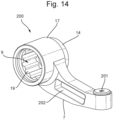
- FIGS 14 and 15A-15C show a support device 200.
- the support device is also referred herein as an External Torque Support (ETS) bracket.
- the support device 200 is formed by a functional and physical integration of the adapter 3 and the cam 5, which have been described in view of Figures 1-13 .
- the support device 200 is made up of a single body, having cam hole 9 for receiving the hollow shaft S in a rotationally interlocking manner.
- the cam hole 9 has spline teeth for interlocking with spline teeth on an outer circumferential surface of the of the hollow shaft S.
- the support device 200 also comprises a through hole 19 that extends through the support device 200.
- the through hole 19 is coaxial with the cam hole 9 for allowing a thru-axle 106 to extend there through.
- a second face 17 of the support device 200 has a boss 14.
- the boss 14 is suitable for fitting inside the drop out recess 33.
- the boss 14 extends around the through hole 9.
- the boss 14 is substantially circular, for aligning the through hole 9 with a hole in the dropout 104, and to allow for a rotation of the support device 200 within the dropout recess 33.
- the boss 14 has a key shape which matches a key-hole shape in the drop-out. In this case the torque can be fully or partially supported within the key-hole in one or two rotation directions.
- the support device 200 also comprises a base 7.
- the base 7 extends outward from a remainder of the support device 200, in a direction transverse to an axial direction of the through hole 9.
- the base 7 is arranged to engage the bicycle frame.
- the base 7 forms a lever arm to support torque that is exerted on the hollow shaft S onto the frame 31.
- the base 7 engages the chain-stay 310 of the bicycle frame 31, and extends in a longitudinal direction L of the bicycle.
- the base 7 comprises an abutment surface 201 arranged for abutting the frame 31.
- the base can be touching directly on the frame and/or the abutment surface 201 can particularly engage a disc-brake mount connector 205, such as in this example, here via a bolt.
- the base 7, in this example, is not affixed to the frame 31. It will be clear that nevertheless the base 7 can transfer torque onto the frame 31 at least in one rotational direction. It will be appreciated that the base 7 can be affixed, for example bolted, to the frame 31, e.g. by the bolt of the disc-brake mount connector.
- the torque support device 200 comprises a cavity 202 for accommodating electrical components, e.g. the first transmitter 120, the second receiver 124, the processor 116A, the battery 128 and/or an antenna e.g. for the second receiver 124. Similar as described in view of the examples shown in Figures 12 and 13 , the first transmitter 120, the second receiver 124, the battery 128, and/or an antenna e.g. for the second receiver 124, can thus be arranged in the cavity 202 of the torque support device 200 or connected to the torque support device 200.
- electrical components e.g. the first transmitter 120, the second receiver 124, the processor 116A, the battery 128 and/or an antenna e.g. for the second receiver 124.
- the first transmitter 120, the second receiver 124, the battery 128, and/or an antenna e.g. for the second receiver 124 can thus be arranged in the cavity 202 of the torque support device 200 or connected to the torque support device 200.
- FIGS 16A-16C show a wheel securing device 300, not according to the claims, for securing a wheel to a bicycle frame 31.
- the securing device comprises a thru-axle 106 that is engageable with a dropout 104 of the bicycle frame 31.
- a thru-axle handle 301 is provided at a proximal end P of the thru-axle 106 .
- a threaded tip 302 is provided, having an external thread 303 for engaging a complementary internal thread of the dropout 104.
- the threaded tip is detachably coupled to the distal end of the thru-axle 106.
- the handle 301 can be used to provide the thru-axle 106 through the holes in the front or rear dropouts of the bicycle frame 31 and through a corresponding front or rear wheel hub, so as to secure the wheel hub, and thus the wheel, to the frame 31.
- the handle 301 extends substantially transverse to the axial direction of the thru-axle 106, to facilitate the screwing of the thru-axle 106 into the dropout.
- the distal end D of the thru-axle 106 comprises an axial spline 305 arranged for cooperating with an axial spline 306 of the tip 302, to establish a rotationally rigid coupling between the thru-axle and the tip 302.
- the tip 302 is rigidly fixed to the thru-axle, here by means of a threaded connector 312 which extends through an axial through hole 308 of the tip 302 and into an axial bore 309 of the thru-axle 106.
- handle 301 can be adjusted relative to the frame 31, in particular relative to the chain-stay 310 and seat-stay 311. Thread of the tip can be machined so as to have multiple engagement starting points, to facilitate the insertion of the insert 302 into the dropout through hole.
- the handle 301 can end up in various angular orientations with respect to the frame 31, after screwing the insert 302 in the dropout 33. Some of these orientations may be aerodynamically suboptimal.
- the handle 301 orientation can be adjusted, after the tip has been inserted into the dropout 33, by detaching the thru-axle 106 from the tip 302.
- the thru-axle 106 can be detached from the tip 302 by unscrewing the connector 12, and axially retracting the thru-axle 106 to disengage the axial splines 305, 306.
- the thru-axle 106 can subsequently be rotated relative to the tip 302 to adjust the angular position of the handle 301, and be re-engaged with the tip 302.
- the splines 305, 306 are configured to allow ten distinct adjustment positions of the thru-axle 106 relative to the insert 302, but it will be appreciated that smaller or larger adjustment-increments can obtained by altering the indexing of the splines 305, 306 accordingly.
- one torque support assembly is mounted on the end of the shaft opposite the sprockets. It will be clear that it is also possible to mount one torque support assembly on the side of the shaft adjacent the sprockets. This is indicated in ghost as 1'. It is also possible to mount a torque support assembly on each end of the shaft.
- the transmission includes a planetary gear with a sun wheel, planet carrier for planet gears and ring gear. It will be appreciated that it is also possible that the planetary gear includes two sun gears and two sets of planet gears.
- any reference signs placed between parentheses shall not be construed as limiting the claim.
- the word 'comprising' does not exclude the presence of other features or steps than those listed in a claim.
- the words 'a' and 'an' shall not be construed as limited to 'only one', but instead are used to mean ⁇ at least one', and do not exclude a plurality.
Landscapes
- Engineering & Computer Science (AREA)
- Mechanical Engineering (AREA)
- Chemical & Material Sciences (AREA)
- Combustion & Propulsion (AREA)
- Transportation (AREA)
- Axle Suspensions And Sidecars For Cycles (AREA)
Description
- The invention concerns a bicycle comprising torque support device, for supporting a torque of a hollow shaft onto a frame of the bicycle.
- A Flat Mount is a disc brake mounting system and an open standard for sport bicycles. In the Flat Mount Brake Assembly (FMBA) a height of the mounting surface(s) for a brake caliper relative to the mounting position of the hub axle is fixed. The mounting surface for a brake caliper is normally fixed within +/- 0.15 mm in height. The height of mounting surfaces can be chosen at the discretion of the frame builder, but is generally between 10 - 35 mm, wherein between frames differences between 10 - 35 mm can be observed quantified in steps of 5 mm. By far the majority of the current gravel and road bikes are compliant with the Flat Mount standard. Furthermore, a substantial amount of bicycle frames today seem to have a cam length of 20-25 mm. In such bicycles switching gears may occur via a fixed transmission to a shaft of a rear wheel axle, or by engaging the shaft of a rear wheel axle. Braking generally occurs by means of a caliper that engages a braking rotor that is supported on the shaft of the axle.
- During the replacement of a wheel, a rear wheel in particular, the fitting of a replacement wheel may be hindered by alignment issues, such as may arise when the braking caliper and braking rotor are misaligned. The person replacing the wheel would have to insert the wheel just right in order to avoid such a misalignment.
-
US2013/0241175 A1 discloses a bicycle with a dropout defining a recess and a torque element that is secured to a first end of an axle and is shaped to fit within the recess of the dropout to inhibit rotation of the axle relative to the frame in response to torque from a motor. - Document
JP H08 337191 A claim 1 and discloses a bicycle comprising: a frame having a dropout; and an axle assembly comprising a hollow shaft (20), a thru-axle (5) and a wheel hub; the axle assembly comprising a torque support device (30), for supporting the torque of the hollow shaft onto the frame of the bicycle, comprising: a cam hole (31) receiving therein a distal end of the shaft, wherein the cam hole and the shaft are interlockingly shaped for rotationally locking the torque support device and shaft with respect to each other; a through hole extending, coaxially with respect to the cam hole, through the torque support device allowing the thru-axle to extend therethrough; a first face for facing the hollow shaft, and a second face facing a dropout recess of the dropout, wherein a boss (34) is extending from the second face; and a base extending from a remainder of the torque support device in a direction transverse to the direction in which the through hole extends, the base being arranged for engaging the frame of the bicycle outside the dropout recess so as to support torque thereon. - The invention is defined by
independent claim 1 and preferred embodiments are defined by dependent claims 2 to 14. - It is an object of the invention to provide a torque support device which overcomes the above mentioned disadvantage. To this end according to an aspect there is provided a bicycle comprising a torque support device according to
claim 1. The device allows for mounting the hollow shaft to the frame, e.g. between the drop outs, such that torque can be transferred from the hollow shaft to the frame, via the device. Thus, the hollow shaft can be prevented from rotating relative to the frame while transferring torque to the frame. Nevertheless, easy mounting and dismounting of the hollow shaft relative to the frame is still possible. - The device comprises a through hole. However, it is also envisaged that the cam hole is an at least partially blind hole.
- Optionally, the device is arranged for supporting at least some torque forces onto the frame via the through hole of the dropout recess of the frame.
- Optionally, the device is arranged for supporting at least some torque forces onto the frame via the brake caliper connection of the frame.
- Optionally, the device is arranged to refrain from supporting torque to the dropout. The device can be arranged to refrain from supporting torque to the dropout recess edge. Then for instance the torque can be supported onto the frame outside the dropout recess, such as outside the dropout, e.g. at the brake caliper connection of the frame.
- Optionally, the device is arranged for supporting at least some torque forces onto the frame via the thru-axle.
- The device comprises a base which, in use, i.e. when mounted to the frame, extends into a length direction of the frame, wherein the base comprises at least one screw seat, for fastening the device there through onto a brake caliper connection of the frame, such that the through hole is aligned with the through hole in the drop out. Optionally, the through hole is aligned with a resting position of the thru-axle in the drop out recess. The brake caliper connection may be a screw connection, such as with an M5 bolt. By fastening the device to the brake caliper connection no modifications need be made to the frame of the bicycle.
- The device may comprise a fixable angularly adjustable connection for adjusting an angle with which the device is fixed to the frame. The angle can be adjustable to allow the device through hole to be aligned with a through hole or rounded end of a shaft mounting slot in the drop out. Alternatively, or additionally, the angle can be adjustable.
- According to an aspect is provided a rear axle assembly, comprising a torque support device according to any of the preceding claims, a wheel hub, and a sprocket or a plurality of sprockets rotatably mounted to the hollow shaft. The hub is rotatably mounted to the hollow shaft and the sprocket(s) are arranged for driving the hub in rotation.
- Optionally, the rear axle assembly comprises a transmission between the sprocket or plurality or sprockets and the wheel hub shaft. The transmission comprises at least two selectable drives between the sprocket(s) and the hub. Hence, additional gear ratios can be provided. For instance the transmission can include a planetary gear set having a first, second and third rotational body. The first rotational body can be a ring gear, the second rotational body can be a planet carrier, and the third rotational body can be a sun gear. The ring gear can be connected to the sprocket(s) and the planet carrier can be connected to the hub. Alternatively, the ring gear can be connected to the hub and the planet carrier can be connected to the sprocket(s). In a first mode the ring gear and the planet carrier are rotationally fixed relative to each other, the transmission operates according to a first gear ratio (such as unity). The sun gear may in that case freewheel relative to the hollow shaft. In a second mode, the ring gear and the planet carrier are not rotationally fixed relative to each other, and the sun gear transfers torque to the hollow shaft, such that the transmission operates according to a second gear ratio (such as 0.5-0.9, e.g. about 0.7). Hence, the transmission can be arranged to transfer torque to the hollow shaft. The transfer of torque requires a proper of transfer of torque from the hollow shaft to the frame, which can be achieved through the device.
- The transfer of torque from the hollow shaft to the device results in a support force on the device and a reaction force. This reaction force can hereby be supported on the frame.
- The device may be arranged for supporting the torque onto the frame via a screw connection, such as via washers, in particular spherical or conical washers. Spherical washers come in sets having a first washer with a concave side and a second washer with a matching convex side. This allows the torque force to be supported e.g. on the the brake mount via the device.
- The device comprises a boss arranged for resting in the dropout recess. This allows the nesting of the device in the drop out recess.
- The device may be a monolithic element.
- The device may be made of one of stainless steel, aluminum, aluminum alloy, titanium, and titanium alloy. However, other materials can be contemplated, such as engineering plastics, surface treated steel, or the like.
- Optionally, the device is made of a combination of reinforced plastic and a metal, such as stainless steel, aluminum, or an alloy.
- The cam hole may comprise spline teeth for interlocking with spline teeth on an outer surface of the shaft.
- Optionally, the device is arranged for being clamped to the frame by the thru-axle. Optionally, the device is arranged for being clamped to the frame via a clamping end of the thru-axle.
- The device can be designed to have an installation height of 20 - 30 mm, such as 25 mm.
- Optionally the at least two selectable drives of the transmission can be selected by an electrically actuatable actuator. Thereto, the electrically actuatable actuator can be arranged on the wheel axle. A rider operable shift control unit, e.g. mounted at the handlebars or frame of the bicycle, can be used for generating a shift signal. The actuator can be controlled on the basis of the shift signal. Hence, the actuator can include an electrical component arranged on the wheel axle which is configured to be controlled by the shift signal.
- Optionally, the device holds a wired or wireless receiver, and/or an antenna therefor, for receiving the shift signal. The wired or wireless receiver can be arranged for receiving the shift signal from the rider operable shift control unit. The device can include an electrical power storage, such as a battery. The power storage can be connected to the wired or wireless receiver.
- Optionally, an electrical connection is arranged between the device, the thru-axle and/or the wheel axle. Thus the shift control signal, or a signal associated with the shift control signal, can be communicated from the device, e.g. from the wired or wireless receiver, to the actuator on the wheel axle, e.g. via the thru-axle and the wheel axle.
- Optionally, a detachable electric connection is provided between the device and the actuator. The detachable electric connection can be provided between the wired or wireless receiver and the actuator
- According to an aspect electric power and/or information is provided to the electric component in or attached to the wheel axle via a contact or contactless electric coupling.
- According to an aspect the device is used for providing the contact or contactless electric coupling between the electric component in or attached to the wheel axle and the power supply and/or control element.
- Optionally, the device is provided with a first transmitter for transmitting electric power and/or signals to the wheel axle. The wheel axle can be provided with a first receiver for receiving electric power and/or the signals from the first transmitter.
- Thereto the device can be provided with a first coil as part of the first transmitter and the wheel axle can be provided with a second coil as part of the first receiver. The first and second coils can be sealed against debris and/or water. The first and second coils are positioned such that when the wheel axle is in the position for securing the wheel in the frame, the first and second coils are axially positioned relative to each other such that a coupling can be achieved at high efficiency, e.g. at maximum efficiency. It will be appreciated that the coils will be coupled inductively. However, since the inductively coupled coils are able to transmit electric power and/or electric signals from one coil to the other, the coupling between the coils is herein also referred to as electric coupling.
- Optionally, the first transmitter is wiredly or wirelessly connected to the control element.
- For increasing efficiency of the transfer of power and/or signal between the coils a middle frequency resonance of the signal on the order of 100 kHz can be used over the coils.
- According to an aspect, the system is arranged for transferring both power and signal between the coils, in one direction or in both directions.
- Alternatively, the thru-axle is provided with the first transmitter for transmitting electric power and/or signals to the wheel axle. Thereto the thru-axle can be provided with a first coil as part of the first transmitter. The first transmitter of the thru-axle can be connected to the receiver in the cam or the adapter, e.g. via a wired electrical connection.
- Optionally, the device includes an actuator controller arranged for controlling the actuator. In that case directing a driving signal to the actuator may suffice. The driving signal can e.g. be a positive or a negative dc current for driving the actuator for up-shift or down-shift, respectively, or vice versa.
- According to an aspect a first energy storage element, such as a battery, is included in or attached to the device and/or thru-axle. A second energy storage element, such as a battery, can be included in or attached to the wheel axle. The first energy storage element can be arranged for providing the first coil with energy. The second energy storage element can be arranged for providing the second coil with energy.
- Optionally, the first energy storage element has a storage capacity that is at least ten (10) times the storage capacity of the second energy storage element.
- Optionally the system is arranged for charging the second energy storage element using energy stored in the first energy storage element. Hence, the second energy storage element can be maintained in a state of sufficient charge. Thereto energy can be transferred from the first energy storage element to the second energy storage element via the first and second coils.
- The system can be arranged for providing energy to an actuator and/or sensor included in or attached to the wheel axle from the second energy storage element. The system can be arranged for providing energy to an actuator and/or sensor included in or attached to the wheel axle from the first energy storage element. This can also be done via the electrical contacts.
- The system can be arranged for transferring a signal determining an actuation direction and/or amount for the actuator included in or attached to the wheel axle via the first and second coils, or via the electrical contacts. The system can be arranged for transferring a signal from the control element (e.g. on the handlebars) to the device and/or thru axle. Signal transfer from the control element (e.g. on the handlebars) to the device and/or thru-axle can be wireless. A second wireless receiver or transceiver can be included in or attached to the device and/or thru-axle. The second transceiver or receiver is herein further referred to as second receiver, nevertheless still covering the possibility of it being a transceiver. The second wireless receiver can be mounted to the device so as to extend outside the wheel axle to reduce disturbance of wireless communication by metal parts of the wheel axle and/or frame. The system can be arranged for providing the second receiver with electric power from the first energy storage element.
- It will be appreciated that when exchanging the wheel (and thus the wheel axle), the device and/or thru-axle can remain with the frame so that a pairing between the control element and the second receiver in/on the device and/or thru-axle can be maintained. Therefore, when exchanging the wheel no time is lost on pairing the control element with the replacement wheel.
- The pairing of the control element, e.g. of a wireless transmitter of the control element, with the second receiver in/on the device and/or thru-axle can be performed, e.g. once when matching the device and/or thru-axle with the frame.
- It will be appreciated that it suffices to recharge the first energy storage element, e.g. by external charging, e.g. using an electric charging apparatus. The second energy storage element can be charged from the first energy storage element. Since the first energy storage element is included in or attached to the device and/or thru-axle, it can easily be charged e.g. via a connector on the device and/or thru-axle. Charging can be performed while leaving the device and/or thru-axle in the bicycle or with the device and/or thru-axle removed from the bicycle. Optionally, the first coil can be used for charging the first energy storage element, e.g. via an external charger, e.g. including a third coil.
- The system can be arranged such that the first energy storage element automatically charges the second energy storage element so that the second energy storage element can always provide the actuator with electric power. In this way also the user never needs to charge or replace the second energy storage element. This provides a big advantage as the second energy storage element can be difficult to reach since it may be mounted in or attached to the wheel axle, and because parts in the neighborhood of the second energy storage element can rotate (e.g. wheel hub and/or driver).
- According to an aspect an electric generator is included in or attached to the wheel axle for charging the second energy storage element. The generator can be driven by rotation of the hub and/or driver. Alternatively, or additionally, the generator can be arranged for generating electric energy on the basis of vibrational energy.
- Optionally the first energy storage element includes one or more, such as two, AAAA (LR61) batteries that can be rechargeable and/or replaceable.
- According to an aspect a control unit can be included in or on the device and/or thru-axle. The control unit can be arranged for receiving control signals from the control element. The control unit can be arranged for converting input signals received from the control element into signals to be transmitted to the first receiver. The control unit can be arranged for indicating a current direction and/or current level to be transmitted by the first transmitter to the first receiver.
- According to an aspect an actuator control unit is included in or attached to the wheel axle for controlling the actuator of the wheel axle. The actuator control unit can be arranged for controlling an electric current direction and/or an electric current amount and/or an electric current duration to the actuator. The actuator control unit can also be arranged for controlling a current, e.g. limiting a current to the actuator.
- Optionally the actuator control unit is mounted on and/or in the device and/or thru-axle.
- Optionally the actuator control unit is connected via first electrical contacts on the device and/or thru-axle to second electrical contacts on the wheel axle.
- Optionally there is no second energy storage on the wheel axle.
- Optionally, the one or more of the actuator, the actuator control unit, the second coil and the second energy storage element are mounted to a bracket, the bracket forming part of or being connected to the wheel axle. Hence, the electronics can easily be mounted to the wheel axle.
- Optionally, the first receiver is powered with electric power received from the first transmitter. Even then, the second energy storage element can be present for providing electric power to the electric component, such as the actuator for gear shifting.
- Optionally, the first transmitter is mounted to a dropout of the frame. Alternatively, if a rear derailleur is available, the first transmitter can be mounter to the rear derailleur.
- The control element can be an electronic switch actuatable with a rotary button or push button. Optionally, the electronic switch is arranged to be actuated via a cable extending from a mechanical switch (shifter), e.g. mounted on the handlebars. Hence, standard mechanical switches (shifters) can be used for actuating the electric component on/in the wheel axle.
- Optionally, a connection between the control element, e.g. the electronic switch, and the first transmitter is a wired or wireless connection. The power supply element for power supply of the first transmitter can be mounted adjacent to the first transmitter, adjacent to the switch or somewhere in between, e.g. inside the frame of the bicycle.
- By using a short range wireless system for the first transmitter and first receiver, no pairing of the first transmitter and first receiver is required. Any wheel, with a first receiver, that is placed in the frame can immediately be controlled by the first transmitter and first receiver, without a pairing procedure. This can be of great advantage for a fast wheel exchange. Similarly, providing the electrical contacts between the cam and/or thru-axle and the wheel axle provides that no pairing procedure is required.
- In case an electrically switching rear derailleur is used, the first transmitter of the short range wireless system can be placed close to an electric component, such as an actuator, of the rear derailleur. In case the rear derailleur is also actuated wirelessly, a third receiver of the rear derailleur can be placed in one housing together with the first transmitter of the short range wireless system and/or with the actuator control unit. A battery used for the rear derailleur can then supply power to the third receiver of the rear derailleur, the actuator of the rear derailleur and the first transmitter of the short range wireless system and/or the actuator controller, and even to the electric component. Hence, fewer batteries are required.
- According to an aspect the electric component has only two modes between which can be switched. The electric actuator can e.g. have only two positions between which can be switched. Optionally, the component is arranged such that the switching direction is determined by an electric current direction (or voltage polarity) to the component. Hence it can be possible to switch from one mode to the other by reversing the current direction (or voltage polarity). Hence, a separate control signal may not be required for determining the switching direction.
- According to the invention a bicycle comprising a torque support device is provided, for supporting a torque of a hollow shaft onto a frame of the bicycle. The torque support device comprises a cam hole for receiving therein a distal end of the shaft, wherein the cam hole and the shaft are interlockingly shaped for rotationally locking the torque support device and the shaft with respect to each other; a through hole extending, coaxially with respect to the cam hole, through the torque support device for allowing a thru-axle to extend therethrough; a boss configured for resting in the dropout recess and a base extending from a remainder of the torque support device in a direction transverse to the direction in which the through hole extends, the base being arranged for engaging the frame of the bicycle so as to support torque thereon. Hence, the torque support device can support torque on the frame of the bicycle in at least one rotation direction about the longitudinal axis of the hollow shaft. A torque applied to the hollow shaft can be transmitted to the torque support device, wherein the torque support device in turn transmits the torque through the base to the bicycle frame. In other words, the torque support device blocks a rotation of the hollow shaft, being lockingly engaged in the cam hole of the support device, by engaging the frame with the base of the support device. Hence, the base of the torque support device may form a lever arm with respect to a rotation axis of the hollow shaft. The base is arranged for engaging the frame of the bicycle outside the dropout recess. Thus the base can support torque on the part of the frame not being the dropout.
- The cam and the adapter as described herein, can for example be integrated, e.g. rigidly coupled to each other, to form the torque support device. It will be appreciated that any of the features and options described in view of the torque support assembly apply equally to the torque support device. The invention is however defined by
claim 1. - The torque support device may be constructed as a single body, e.g. made of stainless steel, aluminum, aluminum alloy, titanium, titanium alloy or a combination thereof. Other materials can be contemplated, such as engineering plastics, surface treated steel, or the like.
- Optionally, the torque support device is configured to be nested in a dropout recess of the frame of the bicycle. It is possible that the torque support device is configured not complementary to the shape of the dropout recess to avoid transfer of torque at the dropout recess.
- The torque support device comprises a first face for facing the hollow shaft, and a second face for facing a dropout recess, wherein a boss, extending from the second face, is configured for resting in the dropout recess.
- Optionally, the base comprises an abutment surface arranged for abutting the bicycle frame. The abutment surface may be arranged at a lateral side of the base at or near an open end of the base.
- Optionally, the abutment surface is configured for abutting a disc-brake mount connector, e.g. a bolt. The abutment surface is for example recessed with respect to the base, for accommodating the bolt at least partly in the recess of the base. The base may be affixed to the frame, e.g. by means of the same connector as the disc-brake is coupled to the frame. However, the torque support device need not affixed to the frame. For instance, the base may only abut against the frame to prevent a rotation of the hollow shaft in an intended rotation direction. This rotation direction may be associated with forward driving direction of the bicycle, and/or a driven rotation direction exerted by a cyclist to drive the bicycle rear wheel. In an opposite rotation direction, the hollow shaft may not be expected to exert a large torque on the torque support device. A rotation in the opposite direction can for example be prevented by an axial clamping force, clamping the hollow shaft between two opposite dropouts. The friction associated with this axial clamping forces may be sufficient to prevent a rotation of the torque support device in said opposite direction. The clamping force may be established by the thru-axle that is provided through the through hole of the torque support device and through the hollow axis, and is arranged to engage the bicycle frame at the dropouts. The thru-axle may thus clamp the torque support device between one of the dropouts and the hollow shaft.
- Optionally, the abutment surface is spaced a distance from a center of the cam hole e.g. 60-90 mm, in particular about 70mm or 80mm, and/or corresponding to a distance of either a 140mm and/or 160mm disc brake mount position. For example, the abutment surface is spaced a distance from a center of the cam hole corresponding to a distance at which a 140mm and/or 160mm disc brake mount connector, e.g. a bolt, is spaced from the cam hole center.
- A further not claimed aspect, provides a wheel securing device for securing a wheel to a bicycle frame, comprising a thru-axle that is engageable with a dropout of the bicycle frame; wherein the thru-axle is provided, at a proximal end thereof, with a thru-axle handle, and, at a distal end thereof, with a threaded tip having a first external thread for engaging a complementary internal thread of the dropout, wherein the threaded tip is detachably coupled to the distal end of the thru-axle. The handle may be used to provide the thru-axle through the holes in the front or rear dropouts of the bicycle frame and through a corresponding front or rear wheel hub, so as to secure the wheel to the frame. At the distal end of the thru-axle, the tip can be screwed into the dropout. The handle may extend substantially transverse to the axial direction of the thru-axle, to facilitate the screwing of the thru-axle into the dropout. The threading and dimensions may vary, however, between bicycle frames. By providing a detachable tip, a single thru-axle can be made compatible for various bicycle frame dropout. The tip can for instance be exchanged with another, different, tip that is compatible with another, different, bicycle frame dropout. Moreover, the tip may be detached from the thru-axle while the tip is threaded into the dropout. This way, the angular orientation of the thru-axle with respect to the frame can easily be adjusted. It will be appreciated that the tip can be an insert, bush or other tip detachably couplable to the distal end of the thru-axle.
- Optionally, the distal end of the thru-axle comprises an axial spline arranged for cooperating with an axial spline of the threaded tip. Hence, the thru-axle and the tip can easily be coupled to each other, while providing a rigid rotational coupling between thru-axle and the tip. Moreover, in use, when the thru-axle is engaged with the bicycle frame, the angular orientation of the thru-axle can easily be adjusted relative to the frame. This allows the handle to be oriented at a desired orientation relative to the frame, e.g. to minimize aerodynamic drag.
- Optionally, the axial splines are configured to provide at least ten distinct relative angular positions between the thru-axle and the tip. Hence, an angular orientation of the thru-axle with respect to the tip can be adjusted with increments of at most 18 degrees. This provides a fine adjustment of the thru-axle orientation and/or the handle orientation, with respect to the frame, in particular with respect to either a chain-stay or a seat-stay of the bicycle frame. Providing at least ten distinct relative angular positions between the thru-axle and the tip enables the handle to be substantially aligned with either the chain-stay or the seat-stay, which typically enclose an angle of about 18 degrees.
- Optionally, the tip is rigidly fixable to the thru-axle by means of a connector, such as a, e.g. threaded, connector which extends through an axial through hole of the tip and into an axial bore of the thru-axle. This enables a secure detachable coupling between the tip and the thru-axle.
- Optionally, the wheel securing device comprises a further threaded tip having a further external thread different from the external thread of the tip, and wherein the tip and the further tip are exchangeable.
- It will be appreciated that the wheel securing device, can be used for securing various wheel hubs and bicycle frames. It will also be appreciated that the wheel securing device can be used in combination with a torque support device as described herein, and/or a torque support assembly as described herein.
- According to the invention there is provided a bicycle comprising the rear axle assembly as described above and a torque support device as described above.
- Further advantageous aspects of the invention will become clear from the appended description and in reference to the accompanying drawings, in which:
-
Figure 1 shows a side view of a not claimed torque support assembly; -
Figure 2 shows perspective view of a shaft part for connecting to the cam of the torque support assembly; -
Figure 3 shows a first perspective view of an adapter of the torque support assembly; -
Figure 4 shows a second perspective view of the adapter of the torque support assembly; -
Figure 5 shows a first perspective view of the cam of the torque support assembly; -
Figure 6 shows a second perspective view of the cam of the torque support assembly; -
Figure 7 shows a side view of the adapter mounted to a rear frame part of a bicycle; -
Figure 8 shows a side view of the rear frame part of the bicycle; -
Figure 9 shows a perspective of a cam, a braking disk, and a gear box axially aligned; -
Figure 10 shows a perspective of the torque support assembly; -
Figures 11A and 11B shows perspective views of the assembly; -
Figure 12 shows a schematic cross-sectional drawing of a rear axle assembly comprising a torque support assembly; and -
Figure 13 shows a schematic cross-sectional drawing of a rear axle assembly comprising a torque support assembly; -
Figure 14 shows a torque support device; -
Figures 15A-15C show a torque support device; -
Figures 16A-16C show a not claimed securing device. -
Figure 1 shows an example of atorque support assembly 1, not according to the claims, herein also referred to as External Torque Support (ETS) bracket. In the example ofFigure 1 the torque support assembly includes anadapter 3 and acam 5. Theadapter 3 is fixable to the frame of a bicycle via abase 7. In use, thebase 7 extends outward in a longitudinal direction L of the bicycle. Thecam 5 can be seen to comprise acam hole 9 for receiving therein adistal end 11 of a shaft S as shown inFigure 2 . Thehole 9 and the shaft S are in this example interlinkingly shaped for rotationally locking thecam 5 and shaft S with respect to each other. To this end here thecam hole 9 has spline teeth for interlocking with spline teeth on an outer circumferential surface of the of the shaft S at thedistal end 11. Theadapter 3 has afirst face 13 as shown inFigure 3 . Thefirst face 13 defines aseat 15 for thecam 5. Theadapter 3 has asecond face 17 as shown inFigure 4 , opposite thefirst face 13. In this example thesecond face 17 is arranged for being inserted therewith into arecess 33 of a drop out of the frame. Theadapter 3 includes an adapter throughhole 19 which extends from theseat 15 on thefirst face 13 to thesecond face 17. In mounted condition the adapter throughhole 19 is coaxial with thecam hole 9 for allowing a thru-axle to extend there through. Theadapter 3 in this example has anupstanding wall 21, extending outward from thefirst face 13. Theupstanding wall 21 defines aninner support surface 23 of theseat 15 against which thecam 5 is supported against rotation when assembled.Figures 5 and6 each show opposite faces of thecam 5. In this example thecam 5 is arranged such thatcam hole 9 has a reduced diameter at aseating face 25. Theseating face 25 is the face of thecam 5 which is to be seated in theseat 15 of theadapter 3. Due to the reduced diameter the distal end of theshaft 11 is supported in thecam 5, but is prevented from extending beyond thecam 5 to theadapter 3. Here thecam 5 can further be seen as having atooth 27. Thetooth 27 has anupper surface 29 which is arranged to be supported against theinner support surface 23 of theadapter 3. In this example each of thecam 5 andadapter 3 are a monolithic element, here made of metal. In this example the metal is stainless steel, but this may just as well be a titanium or aluminum alloy. It will be appreciated that other materials may be selected for the cam and/or the adapter as well. -
Figure 7 shows an example of theadapter 3 of thetorque support assembly 1 installed on a lower rear end of abicycle frame 31, here at a drop out. Thebicycle frame 31 in this example is compliant with the Flat Mount standard in that it comprises a drop outrecess 33 which is visible inFigure 8 .Figures 7 and8 show the same rear end of thebicycle frame 31. In this example aridge height 35 of brake mounts is 20 mm. In this example theadapter 3 is designed for a ridge height of 25 mm. This is to show that a larger adapter, designed for a 25 mm ridge height, may also fit to rear frame part with a different ridge height such as the one presented inFigures 7 and8 . Here the difference in height is compensated for by providing aspacer 39 to a screw connection with theframe 31. It is noted that such aspacer 39 will not be necessary when the adapter is fitted to a frame having a corresponding ridge height of 25 mm. Alternatively theadapter 3 may be designed such that its height is different, such as 15, 20, 25, 30, 35 mm. For ridge heights larger than the adapter height, a bracket (not shown, but customary) can be provided in order to facilitate a connection with the frame such that the adapter throughhole 9 becomes aligned with the thru-axle throughhole 19 of such aframe 31. Returning toFigure 4 in this example theadapter 3 has aboss 14, on a face opposite the face defining theseat 13 for thecam 5. Theboss 14 is suitable for fitting inside the drop outrecess 33, as e.g. shown inFigure 7 . Theboss 14 extends around the adapter throughhole 9 and downwards toward thebase 7 of theadapter 3. In this example, at thebase 7 of theadapter 3 toward a foot, or outwardly extending end of thebase 7, theboss 14 and theupstanding wall 21 merge. It will be appreciated that in this example theboss 14 has an external shape that differs from an internal shape of the drop outrecess 33. As such, in this example theadapter 3 does not transfer torque onto the drop out via theboss 14. Instead, in this example, torque is transferred from theadapter 3 onto the frame via thebase 7 and thebrake caliper connection 37. - The
adapter 3 for 25 mm ridge heights, may be designed to have a weight of about 30 grams, when made of stainless steel. Thecam 5 may be designed to have a weight of about 28 grams, when made of stainless steel, or about 10 grams, when made of an aluminum alloy. - It will be understood that a lower surface of the mount of the
frame 31 onto which theadapter 3 may be fixed may not follow strict tolerances. To be able to use such lower surface, in particular the brake caliper connection 37 (also herein referred to as a bolt connection), as a stop, theadapter 3 may be skewed or tilted with respect to theframe 31. The term "a stop" here meaning a surface on theframe 31 onto which theadapter 3 may support torque forces as a result of supporting torque forces of thecam 5 andcorresponding shaft 11. Difference in height and skew can be compensated for by using spherical orconical washers 39 andspacers 41 added to the bolt connection with abrake caliper connection 37. As such, theadapter 3 can be brought in alignment such that the adapter throughhole 9 is coaxial with ahole 30 through the drop out. Theadapter 3 can also be aligned such that thebase 7 of theadapter 3 extends parallel to the bottom of theframe 31, e.g. the lower surface of the frame. This allows force to be supported across opposing surface of theframe 31 andadapter 3, and can increase durability of the connection. -
Figure 7 shows anETS angle 43 and minimum angle ofentry 45. The ETS angle is defined by theupstanding wall 21. Theupstanding wall 21 partly extends around the adapter throughhole 19 such that opposing parts of thesupport surface 23 around the adapter throughhole 9 diverge from each other in a downward direction D. The angle of the above divergence is theETS angle 43. The angle which the forward portion of thesupport surface 23 makes with respect to a horizontal plane H is herein referred to as the minimum angle ofentry 45. - A wheel is normally held between two drop out
recesses 33 of theframe 31. The drop outs extend, in use, on opposite sides of the wheel. Each dropout includes a throughhole 30 or a slot, e.g. having a rounded end, for allowing a thru-axle to be mounted there through. It s possible that for one wheel a bicycle comprises onetorque support assembly 1. The torque support assembly can be positioned on the end of the hollow shaft adjacent the sprocket(s) or on the opposite end. It is also possible that the bicycle includes for one wheel two torque support assemblies, one on either side of the wheel. To this end the shaft S as shown inFigure 2 may have a second distal end designed the same as thedistal end 11 shown therein. - The
angle 34 of the downward sloping sides of thedropout recess 33 is such that a hub with disc can be placed without the disc jamming in / against the caliper (the caliper falls "over" and "around" the disc). Thisdropout angle 34 is fixed at various values for different bicycles. - By working towards ensuring that the mounting surface of the ETS bracket, also known as the
adapter 3 on theframe 31 is always aligned as parallel as possible to thebrake mount 37 as shown inFigure 7 , anentry angle 45 in the ETS bracket can be created that is smaller than thedropout entry angle 32 of the frame itself. Thetotal dropout angle 34 for dropout recesses 33 as shown inFigure 8 varies greatly, e.g. from 5 degrees to 40 degrees. A drop outentry angle 32, different from adropout insertion angle 34 is also shown inFigure 8 . By choosing theangle 43 of the ETS bracket beyond the range of thedropout insertion angle 34 range, it is ensured that the ETS End Cap, also known as thecam 5, will never give an obstruction to the hollow shaft S when mounting, and at the same time aligns itself as soon as the hollow shaft S reaches its final position. This is represented inFigure 10 , wherein theadapter 3 is made transparent to show theETS angle 43 with respect to the drop outinsertion angle 34. -
Figure 9 shows how the orientation of theETS End cap 5 can very with respect to a horizontal through plane HT to remain guidable into itsseat 15 as shown inFigure 7 . The ETS End Cap 5 (cam), aligns itself in the ETS Bracket 3 (adapter), regardless of the angle at which it is offered provided theadapter 3 is presented in a manner concordant withFigure 9 ). The alignment can be seen inFigures 11A and 11B where thesupport surface 23 guides thecam 5 into alignment with theadapter 3 such that the cam and adapter throughholes -
Figure 12 shows a schematic cross section of a rear (wheel)axle assembly 100. InFigure 12 thewheel axle assembly 100 is mounted in arear frame 31 of a bicycle. Theaxle assembly 100 is mounted between twodropouts 104 of theframe 31. Thewheel axle assembly 100 includes a thru-axle 106 for securing thewheel axle assembly 100 to theframe 31. The thru-axle 106 here is inserted through the hollow shaft S. Thetorque support assembly 1 is interposed between thedropout 104 and the hollow shaft S on the side opposite the sprockets. - In this example, the
wheel axle assembly 100 includes ahub 108. Thewheel axle assembly 100 includes adriver 110 for driving the hub in rotation via atransmission 114. Here thedriver 110 includes acassette 112 including a plurality of sprocket gears. - In this example, the
driver 110 is connected to thehub 108 via thetransmission 114. Thetransmission 114 is arranged to selectively be in a first mode and in a second mode. In the first mode a transmission ratio of thetransmission 114 is different from a transmission ratio in the second mode. Here, in the first mode the transmission ratio is e.g. unity (output rotation speed at the hub equals input rotation speed at the driver). Here, in the second mode the transmission ratio is e.g. a speed reduction (output rotation speed at the hub is smaller than the input rotation speed at the driver). Hence, the transmission can e.g. mimic the functioning of a front derailleur. - In
Figure 12 thewheel axle assembly 100 includes an electric component 116. Here, the electric component 116 is an electric actuator arranged for actuating the transmission to switch from the first mode to the second mode and vice versa. The actuator can e.g. include aprocessor 116A and a motor 116B. In this example theprocessor 116A and the motor 116B are both located on or connected to the rotating part, here in thehub 108. It is also possible that theprocessor 116A and the motor 116B are both located on or connected to the stationary part, here the shaft S. It will be appreciated that it is also possible that part of the electric component, e.g. the motor 116B, is placed on the rotating part, e.g. inside thehub 108 or driver 110and another part of the electric component, e.g. theprocessor 116A, is located on the non-rotating part, e.g. on the shaft S, or on or in thecam 5, or on or in theadapter 3. It will be appreciated that the electric component can also e.g. be a sensor, such as a speed sensor, a torque sensor, or the like. - In this example, for operating the electric component 116, here the actuator, a
first wireless receiver 118 is placed in thewheel axle assembly 100. Here, thefirst receiver 118 is placed within thecassette 112, more specifically within thedriver 110, e.g. near the actuator 116. Afirst wireless transmitter 120 is placed on a non-rotating part of the bicycle. Here thefirst transmitter 120 is placed on or in theadapter 3, or on or in thecam 5. Alternatively, thefirst transmitter 120 can be placed on the thru-axle 106, bicycle frame, or handle bar. If the wheel including thewheel axle assembly 100 is exchanged thetransmitter 120 may remain with the frame. The communication between thefirst transmitter 120 and thefirst receiver 118 can be such that it requires no pairing. Hence, a wheel exchange is very simple and fast. - In
Figure 12 , thefirst transmitter 120 is communicatively coupled, here wiredly, with asecond receiver 124. Here the second receiver is also placed on or in theadapter 3, or on or in thecam 5. Thesecond receiver 124 is in this example arranged for wirelessly receiving a control signal from asecond transmitter 126. Thesecond transmitter 126 can be associated with amanual input module 127, such as a shifter, for shifting gears. Theshifter 127 can e.g. be mounted on handlebars of the bicycle. Thesecond transmitter 126 can also be mounted in the handlebars or frame. Acontroller 129 can include aprocessor 125 for processing manual input from themodule 127. Thecontroller 129 can include indicator means 123 for indicating a status to the user. Hence a user (rider) can trigger transmission of the control signal by actuating the shifter. Alternatively, or additionally, the control signal transmitted by thesecond transmitter 126 can be automatically generated by a processor, e.g. theprocessor 125 of thecontroller 129. Thesecond transmitter 126 can also be arranged to transmit a control signal to another shifting device on the bicycle. - The
first transmitter 120 and thesecond receiver 124 are powered by abattery 128. In this example, thebattery 128 is attached to theadapter 3, or on or in thecam 5. It is also possible that thebattery 128 is included in the thru-axle 106, e.g. within the hollow shaft S. It is also possible that theadapter 3 and/or thecam 5 is wiredly connected to thecontroller 129 on the frame. Then thesecond transmitter 126 andsecond receiver 124 can be omitted. Also, thebattery 128 can be omitted in case thefirst transmitter 120 then is powered, e.g. wiredly, from the controller 129 (e.g. from abattery 131 of the controller). - In
Figure 13 the electric component 116, e.g. the actuator, arranged for actuating the transmission to switch from the first mode to the second mode and vice versa, is wiredly connected to thesecond receiver 124. More precisely, in this example, theprocessor 116A is connected to a non-rotating part and the motor 116B is connected to a rotating or non-rotating part of thewheel axle assembly 100.. Here, thesecond receiver 124 and theprocessor 116A are included in or on thecam 5. The wired connection from thesecond receiver 124 to theprocessor 116A is within the cam. It will be appreciated that it is also possible that thesecond receiver 124 and theprocessor 116A are included in or on theadapter 3. It will be appreciated that theadapter 3 and thecam 5 can be a unitary part. The wired connection from thesecond receiver 124 to theprocessor 116A can be within thecam 5 or in or on theadapter 3, e.g. both thesecond receiver 124 and theprocessor 116A can be on the same PCB, in or on theadapter 3, in or on thecam 5, or in or on both. - The wired connection from the
processor 116A to the motor 116B here only carries power signals to the motor 116B, here a positive or negative dc current. In this example, the wired connection from theprocessor 116A to the motor 116B is achieved by a wired connection from thecam 5 and/or theadapter 3 to the hollow shaft S. Thereto thecam 5 may have, first electrical contacts 133 e.g. at the spline teeth at thecam hole 9, and the shaft S may have matching secondelectrical contacts 135 e.g. at the spline teeth at thedistal end 11 of the shaft S. The electrical contacts can be in axial direction or in radial direction between thecam 5 and the shaft S. In this example, when exchanging the wheel, thecam 5 may remain with the bicycle as the cam includes thesecond receiver 124. Thecam 5 can be disconnected from the wheel, e.g. from the shaft S, or it can stay on the bicycle wheel. It can be advantageous, when changing the rear wheel, that thecam 5 withsecond receiver 124 is disconnected from the wheel and connected to the replacement wheel in order to keep the pairing between thesecond receiver 124 and thesecond transmitter 126. It is also possible that thecam 5 is wiredly connected to thecontroller 129 on the frame. Then thesecond transmitter 126 andsecond receiver 124 can be omitted. - Alternatively, the
second receiver 124 is included in or on thecam 5 and theprocessor 116A is connected to the shaft S. The wired connection from thesecond receiver 124 to theprocessor 116A is then via the first and second electrical contacts. - Alternatively, the first and second electrical contacts between the cam and the shaft S can be used to provide electrical power to an electrical drive motor inside the hub, the stator of which is also connected to the shaft S. The torque support assembly then prevents also rotation of the shaft S due to the reaction torque of the electric motor.
- The
transmission 114 is also coupled to the shaft S. The shaft S is prevented from rotating around its longitudinal axis by means of the torque support assembly. Thetransmission 114 may interact with asupport element 130, such as spline teeth, on the shaft S. This allows gear shifting torque to be exerted onto the shaft S which is supported by thetorque support assembly 1 onto theframe 31. -
Figures 14 and15A-15C show asupport device 200. The support device is also referred herein as an External Torque Support (ETS) bracket. Thesupport device 200 is formed by a functional and physical integration of theadapter 3 and thecam 5, which have been described in view ofFigures 1-13 . In the example offigures 14 and15A-15C , thesupport device 200 is made up of a single body, havingcam hole 9 for receiving the hollow shaft S in a rotationally interlocking manner. Here, thecam hole 9 has spline teeth for interlocking with spline teeth on an outer circumferential surface of the of the hollow shaft S. Thesupport device 200 also comprises a throughhole 19 that extends through thesupport device 200. The throughhole 19 is coaxial with thecam hole 9 for allowing a thru-axle 106 to extend there through. - A
second face 17 of thesupport device 200 has aboss 14. Theboss 14 is suitable for fitting inside the drop outrecess 33. Theboss 14 extends around the throughhole 9. Here theboss 14 is substantially circular, for aligning the throughhole 9 with a hole in thedropout 104, and to allow for a rotation of thesupport device 200 within thedropout recess 33. In a variant of the support device it is possible that theboss 14 has a key shape which matches a key-hole shape in the drop-out. In this case the torque can be fully or partially supported within the key-hole in one or two rotation directions. - The
support device 200 also comprises abase 7. Thebase 7 extends outward from a remainder of thesupport device 200, in a direction transverse to an axial direction of the throughhole 9. Thebase 7 is arranged to engage the bicycle frame. In use, thebase 7 forms a lever arm to support torque that is exerted on the hollow shaft S onto theframe 31. Here, thebase 7 engages the chain-stay 310 of thebicycle frame 31, and extends in a longitudinal direction L of the bicycle. Thebase 7 comprises anabutment surface 201 arranged for abutting theframe 31. The base can be touching directly on the frame and/or theabutment surface 201 can particularly engage a disc-brake mount connector 205, such as in this example, here via a bolt. Thebase 7, in this example, is not affixed to theframe 31. It will be clear that nevertheless thebase 7 can transfer torque onto theframe 31 at least in one rotational direction. It will be appreciated that thebase 7 can be affixed, for example bolted, to theframe 31, e.g. by the bolt of the disc-brake mount connector. - In the example shown in
Figure 14 , thetorque support device 200 comprises acavity 202 for accommodating electrical components, e.g. thefirst transmitter 120, thesecond receiver 124, theprocessor 116A, thebattery 128 and/or an antenna e.g. for thesecond receiver 124. Similar as described in view of the examples shown inFigures 12 and13 , thefirst transmitter 120, thesecond receiver 124, thebattery 128, and/or an antenna e.g. for thesecond receiver 124, can thus be arranged in thecavity 202 of thetorque support device 200 or connected to thetorque support device 200. -
Figures 16A-16C show awheel securing device 300, not according to the claims, for securing a wheel to abicycle frame 31. The securing device comprises a thru-axle 106 that is engageable with adropout 104 of thebicycle frame 31. At a proximal end P of the thru-axle 106 a thru-axle handle 301 is provided. At a distal end D of the thru-axle a threadedtip 302 is provided, having an external thread 303 for engaging a complementary internal thread of thedropout 104. The threaded tip is detachably coupled to the distal end of the thru-axle 106. Thehandle 301 can be used to provide the thru-axle 106 through the holes in the front or rear dropouts of thebicycle frame 31 and through a corresponding front or rear wheel hub, so as to secure the wheel hub, and thus the wheel, to theframe 31. As best seen inFigure 16C , thehandle 301 extends substantially transverse to the axial direction of the thru-axle 106, to facilitate the screwing of the thru-axle 106 into the dropout. - The distal end D of the thru-
axle 106 comprises anaxial spline 305 arranged for cooperating with anaxial spline 306 of thetip 302, to establish a rotationally rigid coupling between the thru-axle and thetip 302. Thetip 302 is rigidly fixed to the thru-axle, here by means of a threadedconnector 312 which extends through an axial through hole 308 of thetip 302 and into an axial bore 309 of the thru-axle 106. - To minimize aerodynamic drag, of
handle 301 can be adjusted relative to theframe 31, in particular relative to the chain-stay 310 and seat-stay 311. Thread of the tip can be machined so as to have multiple engagement starting points, to facilitate the insertion of theinsert 302 into the dropout through hole. Thehandle 301 can end up in various angular orientations with respect to theframe 31, after screwing theinsert 302 in thedropout 33. Some of these orientations may be aerodynamically suboptimal. Thehandle 301 orientation can be adjusted, after the tip has been inserted into thedropout 33, by detaching the thru-axle 106 from thetip 302. In this case, the thru-axle 106 can be detached from thetip 302 by unscrewing the connector 12, and axially retracting the thru-axle 106 to disengage theaxial splines axle 106 can subsequently be rotated relative to thetip 302 to adjust the angular position of thehandle 301, and be re-engaged with thetip 302. Here, thesplines axle 106 relative to theinsert 302, but it will be appreciated that smaller or larger adjustment-increments can obtained by altering the indexing of thesplines - Herein, the invention is described with reference to specific examples. It will, however, be evident that various modifications and changes may be made therein, without departing from the essence of the invention. For the purpose of clarity and a concise description features are described herein as part of the same or separate embodiments, however, embodiments having combinations of all or some of the features described in these separate examples are also envisaged.
- In the examples of
Figures 12 and13 one torque support assembly is mounted on the end of the shaft opposite the sprockets. It will be clear that it is also possible to mount one torque support assembly on the side of the shaft adjacent the sprockets. This is indicated in ghost as 1'. It is also possible to mount a torque support assembly on each end of the shaft. - In a described example, the transmission includes a planetary gear with a sun wheel, planet carrier for planet gears and ring gear. It will be appreciated that it is also possible that the planetary gear includes two sun gears and two sets of planet gears.
- However, other modifications, variations, and alternatives are also possible, such as the addition of an electric drive motor included in the axle assembly, the electric drive motor being connected to the shaft S. The specifications, drawings and examples are, accordingly, to be regarded in an illustrative sense rather than in a restrictive sense.
- In the claims, any reference signs placed between parentheses shall not be construed as limiting the claim. The word 'comprising' does not exclude the presence of other features or steps than those listed in a claim. Furthermore, the words 'a' and 'an' shall not be construed as limited to 'only one', but instead are used to mean `at least one', and do not exclude a plurality.
Claims (14)
- A bicycle comprising:a frame (31) having a dropout (104); anda rear axle assembly (100) comprising a hollow shaft (S), a thru-axle (106), a wheel hub (108), and a sprocket or a plurality of sprockets (112) rotatably mounted to the hollow shaft;the rear axle assembly comprising a torque support device (200), for supporting the torque of the hollow shaft onto the frame (31) of the bicycle, comprising:- a cam hole (9) receiving therein a distal end (11) of the shaft (S), wherein the cam hole and the shaft are interlockingly shaped for rotationally locking the torque support device and shaft with respect to each other;- a through hole (19) extending, coaxially with respect to the cam hole (9), through the torque support device (200) allowing the thru-axle (106) to extend therethrough;- a first face for facing the hollow shaft, and a second face facing a dropout recess (33) of the dropout, wherein a boss (14) extending from the second face, is resting in the dropout recess (33); and- a base (7) extending from a remainder of the torque support device in a direction transverse to the direction in which the through hole extends, the base being arranged for engaging the frame (31) of the bicycle outside the dropout recess so as to support torque thereon.
- The bicycle according to claim 1, wherein the base (7) comprises an abutment surface (201) arranged for abutting the bicycle frame.
- The bicycle according to claim 2, wherein the abutment surface (201) is configured for abutting a disc-brake mount connector (37, 205).
- The bicycle according to claim 2 or 3, wherein the abutment surface (201) is spaced a distance from a center of the cam hole (9) e.g. 60-90 mm, in particular 70mm or 80mm, and/or corresponding to a distance of either a 140mm and/or 160mm disc brake mount position.
- The bicycle according to any of claims 2-4 wherein the abutment surface is recessed with respect to the base, for accommodating a disc-brake mount connector bolt at least partly in the recess of the base..
- The bicycle according to any of the preceding claims, wherein the torque support device is made of one of stainless steel, aluminum, aluminum alloy, and/or titanium alloy.
- The bicycle according to any of the preceding claims, wherein the torque support device is made of a combination of reinforced plastic and a metal, such as stainless steel, aluminum, or an alloy.
- The bicycle according to any of the preceding claims, wherein the cam hole (9) comprises spline teeth for interlocking with spline teeth on an outer surface of the shaft.
- The bicycle according to any of the preceding claims, wherein the torque support device holds a wireless receiver (124) for receiving a shift signal, and/or an electrical power storage.
- The bicycle according to any of the preceding claims, wherein there is an electrical connection between the torque support device (200), the thru-axle (106) and/or the hollow shaft (S).
- A bicycle according to any of the preceding claims, wherein the rear axle assembly comprises a transmission (114) between the sprocket or plurality of sprockets and the wheel hub.
- The bicycle according to claim 11, wherein the transmission (114) includes at least two selectable drives and an electrically actuatable actuator (116) for selecting one of the at least two drives.
- The bicycle according to claim 12 when dependent from claim 9, wherein the receiver (124) is in communication with the actuator, wherein optionally a detachable electric connection is provided between the device and the actuator;
wherein optionally the device includes an actuator controller arranged for controlling the actuator. - The bicycle according to any one of claims 11-13, wherein the torque support device is provided with a first wireless transmitter (120) for transmitting electric power and/or signals to the hollow shaft, and the hollow shaft is provided with a first wireless receiver (118) for receiving the electric power and/or the signals from the first transmitter.
Priority Applications (1)
| Application Number | Priority Date | Filing Date | Title |
|---|---|---|---|
| EP24160097.2A EP4389578A3 (en) | 2020-02-07 | 2021-02-08 | A torque support assembly, a rear axle assembly comprising such a torque support assembly and bicycle comprising the rear axle assembly |
Applications Claiming Priority (4)
| Application Number | Priority Date | Filing Date | Title |
|---|---|---|---|
| NL2024855A NL2024855B1 (en) | 2020-02-07 | 2020-02-07 | A torque support assembly, a rear axle assembly comprising such a torque support assembly and bicycle comprising the rear axle assembly. |
| NL2026323 | 2020-08-21 | ||
| NL2027194 | 2020-12-21 | ||
| PCT/NL2021/050084 WO2021158116A1 (en) | 2020-02-07 | 2021-02-08 | A torque support assembly, a torque support device, a wheel securing device, a rear axle assembly and a bicycle |
Related Child Applications (1)
| Application Number | Title | Priority Date | Filing Date |
|---|---|---|---|
| EP24160097.2A Division EP4389578A3 (en) | 2020-02-07 | 2021-02-08 | A torque support assembly, a rear axle assembly comprising such a torque support assembly and bicycle comprising the rear axle assembly |
Publications (2)
| Publication Number | Publication Date |
|---|---|
| EP4021789A1 EP4021789A1 (en) | 2022-07-06 |
| EP4021789B1 true EP4021789B1 (en) | 2024-02-28 |
Family
ID=74587094
Family Applications (2)
| Application Number | Title | Priority Date | Filing Date |
|---|---|---|---|
| EP21704626.7A Active EP4021789B1 (en) | 2020-02-07 | 2021-02-08 | A bicycle comprising a torque support device |
| EP24160097.2A Pending EP4389578A3 (en) | 2020-02-07 | 2021-02-08 | A torque support assembly, a rear axle assembly comprising such a torque support assembly and bicycle comprising the rear axle assembly |
Family Applications After (1)
| Application Number | Title | Priority Date | Filing Date |
|---|---|---|---|
| EP24160097.2A Pending EP4389578A3 (en) | 2020-02-07 | 2021-02-08 | A torque support assembly, a rear axle assembly comprising such a torque support assembly and bicycle comprising the rear axle assembly |
Country Status (4)
| Country | Link |
|---|---|
| US (1) | US12600430B2 (en) |
| EP (2) | EP4021789B1 (en) |
| CN (1) | CN115427299A (en) |
| WO (1) | WO2021158116A1 (en) |
Cited By (2)
| Publication number | Priority date | Publication date | Assignee | Title |
|---|---|---|---|---|
| US20240030777A1 (en) * | 2021-09-16 | 2024-01-25 | Mahle International Gmbh | Motor device for an electric bicycle |
| WO2026047194A1 (en) * | 2024-08-29 | 2026-03-05 | Classified Cycling Bv | Bicycle transmission system |
Families Citing this family (1)
| Publication number | Priority date | Publication date | Assignee | Title |
|---|---|---|---|---|
| DE102024206101A1 (en) * | 2024-06-28 | 2025-12-31 | Robert Bosch Gesellschaft mit beschränkter Haftung | Wheel hub drive unit |
Citations (6)
| Publication number | Priority date | Publication date | Assignee | Title |
|---|---|---|---|---|
| JPH08337191A (en) * | 1995-06-13 | 1996-12-24 | Shimano Inc | Bicycle hub brake |
| DE102004063505A1 (en) * | 2004-12-26 | 2006-07-06 | Nicolai, Karlheinz, Dipl.-Ing. (TU) | Rear wheel and rear hub for bicycles |
| EP2419658A1 (en) * | 2009-04-16 | 2012-02-22 | Fallbrook Technologies Inc. | Stator assembly and shifting mechanism for a continuously variable transmission |
| EP2557029A1 (en) * | 2011-08-11 | 2013-02-13 | Orbea, S. Coop. Ltda. | Bicycle frame set for building a bicycle frame, with a rear dropout that allows the mounting of different types of wheel axles |
| WO2018199761A1 (en) * | 2017-04-27 | 2018-11-01 | Advancing Technologies B.V. | Bicycle transmission wireless actuation system |
| EP3670315A2 (en) * | 2018-12-21 | 2020-06-24 | SRAM Deutschland GmbH | Support element and bicycle comprising a support element |
Family Cites Families (13)
| Publication number | Priority date | Publication date | Assignee | Title |
|---|---|---|---|---|
| US7654548B2 (en) | 2007-02-16 | 2010-02-02 | Shimano Inc. | Bicycle wheel securing structure |
| US8485335B2 (en) * | 2009-01-02 | 2013-07-16 | Raphael Schlanger | Torque coupling assembly |
| US20120228851A1 (en) * | 2011-03-08 | 2012-09-13 | Jui-Min Chen | Bicycle Whose Front Wheel Can Be Adjusted To A Deviated Position |
| TWM421293U (en) * | 2011-07-11 | 2012-01-21 | Fairly Bike Mfg Co Ltd | Assembling structure for bicycle frame and electric hub |
| US10189305B2 (en) | 2011-08-29 | 2019-01-29 | Sram, Llc | Bicycle front wheel hub with torque tube |
| US9010792B2 (en) * | 2012-03-16 | 2015-04-21 | Specialized Bicycle Components, Inc. | Torque element for a motor-driven bicycle |
| NL2012339A (en) | 2014-02-28 | 2015-10-14 | Dti Advanced Tech B V | Rear axle and rear wheel and bicycle frame for a bicycle |
| NL2012611B1 (en) | 2014-02-28 | 2016-05-09 | Dti Advanced Tech B V | Bicycle with only one front sprocket. |
| DE202014103414U1 (en) | 2014-07-24 | 2015-10-27 | Zeg Zweirad-Einkaufs-Genossenschaft Eg | Thru axle mounting system for rear axles of bicycles and derailleur hanger for this purpose |
| EP3053819A1 (en) * | 2015-01-19 | 2016-08-10 | Cycling Sports Group, Inc. | One-piece disc brake mount for bicycle |
| CN108290616B (en) | 2015-08-28 | 2020-11-20 | 先进技术有限公司 | Transmission between sprocket carrier and hub of bicycle, rear axle and rear wheel |
| US10675913B2 (en) * | 2016-06-24 | 2020-06-09 | Specialized Bicycle Components, Inc. | Bicycle wheel hub with power meter |
| JP6853161B2 (en) * | 2017-11-09 | 2021-03-31 | 株式会社シマノ | Shaft member of wheel fixture and wheel fixture |
-
2021
- 2021-02-08 CN CN202180012752.8A patent/CN115427299A/en active Pending
- 2021-02-08 EP EP21704626.7A patent/EP4021789B1/en active Active
- 2021-02-08 US US17/797,310 patent/US12600430B2/en active Active
- 2021-02-08 WO PCT/NL2021/050084 patent/WO2021158116A1/en not_active Ceased
- 2021-02-08 EP EP24160097.2A patent/EP4389578A3/en active Pending
Patent Citations (6)
| Publication number | Priority date | Publication date | Assignee | Title |
|---|---|---|---|---|
| JPH08337191A (en) * | 1995-06-13 | 1996-12-24 | Shimano Inc | Bicycle hub brake |
| DE102004063505A1 (en) * | 2004-12-26 | 2006-07-06 | Nicolai, Karlheinz, Dipl.-Ing. (TU) | Rear wheel and rear hub for bicycles |
| EP2419658A1 (en) * | 2009-04-16 | 2012-02-22 | Fallbrook Technologies Inc. | Stator assembly and shifting mechanism for a continuously variable transmission |
| EP2557029A1 (en) * | 2011-08-11 | 2013-02-13 | Orbea, S. Coop. Ltda. | Bicycle frame set for building a bicycle frame, with a rear dropout that allows the mounting of different types of wheel axles |
| WO2018199761A1 (en) * | 2017-04-27 | 2018-11-01 | Advancing Technologies B.V. | Bicycle transmission wireless actuation system |
| EP3670315A2 (en) * | 2018-12-21 | 2020-06-24 | SRAM Deutschland GmbH | Support element and bicycle comprising a support element |
Cited By (3)
| Publication number | Priority date | Publication date | Assignee | Title |
|---|---|---|---|---|
| US20240030777A1 (en) * | 2021-09-16 | 2024-01-25 | Mahle International Gmbh | Motor device for an electric bicycle |
| WO2026047194A1 (en) * | 2024-08-29 | 2026-03-05 | Classified Cycling Bv | Bicycle transmission system |
| NL2038522B1 (en) * | 2024-08-29 | 2026-03-13 | Classified Cycling Bv | Bicycle transmission system |
Also Published As
| Publication number | Publication date |
|---|---|
| EP4021789A1 (en) | 2022-07-06 |
| WO2021158116A1 (en) | 2021-08-12 |
| EP4389578A3 (en) | 2024-10-23 |
| US20230049132A1 (en) | 2023-02-16 |
| EP4389578A2 (en) | 2024-06-26 |
| US12600430B2 (en) | 2026-04-14 |
| CN115427299A (en) | 2022-12-02 |
Similar Documents
| Publication | Publication Date | Title |
|---|---|---|
| EP4021789B1 (en) | A bicycle comprising a torque support device | |
| EP2535254B1 (en) | Bicycle chain tensioner device | |
| US20250353576A1 (en) | Rear wheel axle, as well as bicycle frame and rear wheel for a bicycle | |
| JP5546614B2 (en) | Generator and transmission | |
| US12252214B2 (en) | Vehicle power-assist drive systems | |
| US7828101B2 (en) | Self-propelled wheel for bicycles and similar vehicles | |
| US5433284A (en) | Electrical bicycle | |
| JP3215337B2 (en) | Auxiliary power supply for bicycle | |
| CN111433491B (en) | Transmission systems for vehicles | |
| EP2686230B1 (en) | Wheel for pedal-assisted bikes | |
| US10308318B2 (en) | Bicycle derailleur | |
| KR20000076415A (en) | Unitary power module for electric vehicles | |
| CN102869563B (en) | Power supply arrangement on electric bicycles | |
| US9701363B2 (en) | Sensor assembly and drive unit for bicycle and bicycle | |
| JP2019085053A (en) | Shaft member of wheel mounting tool, and wheel mounting tool | |
| WO2015130174A1 (en) | Bicycle | |
| EP2772423B1 (en) | Method of converting regular bike into pedelec | |
| EP2141068A1 (en) | Electric bicycle | |
| EP4377192B1 (en) | Ride-on type vehicle | |
| WO2023236046A1 (en) | Power-assisted drive assembly | |
| US20250042495A1 (en) | Self-powered system for a bicycle | |
| WO2023236047A1 (en) | Power-assisted drive assembly | |
| CA2508974A1 (en) | Self-propelled wheel for bicycles and other vehicles | |
| MXPA99008562A (en) | Unitary power module for electric vehicles |
Legal Events
| Date | Code | Title | Description |
|---|---|---|---|
| STAA | Information on the status of an ep patent application or granted ep patent |
Free format text: STATUS: UNKNOWN |
|
| STAA | Information on the status of an ep patent application or granted ep patent |
Free format text: STATUS: THE INTERNATIONAL PUBLICATION HAS BEEN MADE |
|
| PUAI | Public reference made under article 153(3) epc to a published international application that has entered the european phase |
Free format text: ORIGINAL CODE: 0009012 |
|
| STAA | Information on the status of an ep patent application or granted ep patent |
Free format text: STATUS: REQUEST FOR EXAMINATION WAS MADE |
|
| 17P | Request for examination filed |
Effective date: 20220331 |
|
| AK | Designated contracting states |
Kind code of ref document: A1 Designated state(s): AL AT BE BG CH CY CZ DE DK EE ES FI FR GB GR HR HU IE IS IT LI LT LU LV MC MK MT NL NO PL PT RO RS SE SI SK SM TR |
|
| PUAG | Search results despatched under rule 164(2) epc together with communication from examining division |
Free format text: ORIGINAL CODE: 0009017 |
|
| STAA | Information on the status of an ep patent application or granted ep patent |
Free format text: STATUS: EXAMINATION IS IN PROGRESS |
|
| 17Q | First examination report despatched |
Effective date: 20221024 |
|
| B565 | Issuance of search results under rule 164(2) epc |
Effective date: 20221024 |
|
| RIC1 | Information provided on ipc code assigned before grant |
Ipc: B62M 9/125 20100101ALI20221019BHEP Ipc: B60B 27/02 20060101ALI20221019BHEP Ipc: B62K 25/02 20060101AFI20221019BHEP |
|
| DAV | Request for validation of the european patent (deleted) | ||
| DAX | Request for extension of the european patent (deleted) | ||
| GRAP | Despatch of communication of intention to grant a patent |
Free format text: ORIGINAL CODE: EPIDOSNIGR1 |
|
| STAA | Information on the status of an ep patent application or granted ep patent |
Free format text: STATUS: GRANT OF PATENT IS INTENDED |
|
| INTG | Intention to grant announced |
Effective date: 20230524 |
|
| GRAS | Grant fee paid |
Free format text: ORIGINAL CODE: EPIDOSNIGR3 |
|
| GRAA | (expected) grant |
Free format text: ORIGINAL CODE: 0009210 |
|
| STAA | Information on the status of an ep patent application or granted ep patent |
Free format text: STATUS: THE PATENT HAS BEEN GRANTED |
|
| AK | Designated contracting states |
Kind code of ref document: B1 Designated state(s): AL AT BE BG CH CY CZ DE DK EE ES FI FR GB GR HR HU IE IS IT LI LT LU LV MC MK MT NL NO PL PT RO RS SE SI SK SM TR |
|
| REG | Reference to a national code |
Ref country code: GB Ref legal event code: FG4D |
|
| REG | Reference to a national code |
Ref country code: CH Ref legal event code: EP |
|
| REG | Reference to a national code |
Ref country code: DE Ref legal event code: R096 Ref document number: 602021009840 Country of ref document: DE |
|
| REG | Reference to a national code |
Ref country code: IE Ref legal event code: FG4D |
|
| REG | Reference to a national code |
Ref country code: LT Ref legal event code: MG9D |
|
| PG25 | Lapsed in a contracting state [announced via postgrant information from national office to epo] |
Ref country code: IS Free format text: LAPSE BECAUSE OF FAILURE TO SUBMIT A TRANSLATION OF THE DESCRIPTION OR TO PAY THE FEE WITHIN THE PRESCRIBED TIME-LIMIT Effective date: 20240628 |
|
| PG25 | Lapsed in a contracting state [announced via postgrant information from national office to epo] |
Ref country code: LT Free format text: LAPSE BECAUSE OF FAILURE TO SUBMIT A TRANSLATION OF THE DESCRIPTION OR TO PAY THE FEE WITHIN THE PRESCRIBED TIME-LIMIT Effective date: 20240228 |
|
| REG | Reference to a national code |
Ref country code: NL Ref legal event code: FP |
|
| PG25 | Lapsed in a contracting state [announced via postgrant information from national office to epo] |
Ref country code: GR Free format text: LAPSE BECAUSE OF FAILURE TO SUBMIT A TRANSLATION OF THE DESCRIPTION OR TO PAY THE FEE WITHIN THE PRESCRIBED TIME-LIMIT Effective date: 20240529 |
|
| PG25 | Lapsed in a contracting state [announced via postgrant information from national office to epo] |
Ref country code: HR Free format text: LAPSE BECAUSE OF FAILURE TO SUBMIT A TRANSLATION OF THE DESCRIPTION OR TO PAY THE FEE WITHIN THE PRESCRIBED TIME-LIMIT Effective date: 20240228 Ref country code: RS Free format text: LAPSE BECAUSE OF FAILURE TO SUBMIT A TRANSLATION OF THE DESCRIPTION OR TO PAY THE FEE WITHIN THE PRESCRIBED TIME-LIMIT Effective date: 20240528 |
|
| PG25 | Lapsed in a contracting state [announced via postgrant information from national office to epo] |
Ref country code: ES Free format text: LAPSE BECAUSE OF FAILURE TO SUBMIT A TRANSLATION OF THE DESCRIPTION OR TO PAY THE FEE WITHIN THE PRESCRIBED TIME-LIMIT Effective date: 20240228 |
|
| P01 | Opt-out of the competence of the unified patent court (upc) registered |
Free format text: CASE NUMBER: APP_36732/2024 Effective date: 20240620 |
|
| PG25 | Lapsed in a contracting state [announced via postgrant information from national office to epo] |
Ref country code: RS Free format text: LAPSE BECAUSE OF FAILURE TO SUBMIT A TRANSLATION OF THE DESCRIPTION OR TO PAY THE FEE WITHIN THE PRESCRIBED TIME-LIMIT Effective date: 20240528 Ref country code: NO Free format text: LAPSE BECAUSE OF FAILURE TO SUBMIT A TRANSLATION OF THE DESCRIPTION OR TO PAY THE FEE WITHIN THE PRESCRIBED TIME-LIMIT Effective date: 20240528 Ref country code: LT Free format text: LAPSE BECAUSE OF FAILURE TO SUBMIT A TRANSLATION OF THE DESCRIPTION OR TO PAY THE FEE WITHIN THE PRESCRIBED TIME-LIMIT Effective date: 20240228 Ref country code: IS Free format text: LAPSE BECAUSE OF FAILURE TO SUBMIT A TRANSLATION OF THE DESCRIPTION OR TO PAY THE FEE WITHIN THE PRESCRIBED TIME-LIMIT Effective date: 20240628 Ref country code: HR Free format text: LAPSE BECAUSE OF FAILURE TO SUBMIT A TRANSLATION OF THE DESCRIPTION OR TO PAY THE FEE WITHIN THE PRESCRIBED TIME-LIMIT Effective date: 20240228 Ref country code: GR Free format text: LAPSE BECAUSE OF FAILURE TO SUBMIT A TRANSLATION OF THE DESCRIPTION OR TO PAY THE FEE WITHIN THE PRESCRIBED TIME-LIMIT Effective date: 20240529 Ref country code: FI Free format text: LAPSE BECAUSE OF FAILURE TO SUBMIT A TRANSLATION OF THE DESCRIPTION OR TO PAY THE FEE WITHIN THE PRESCRIBED TIME-LIMIT Effective date: 20240228 Ref country code: ES Free format text: LAPSE BECAUSE OF FAILURE TO SUBMIT A TRANSLATION OF THE DESCRIPTION OR TO PAY THE FEE WITHIN THE PRESCRIBED TIME-LIMIT Effective date: 20240228 Ref country code: BG Free format text: LAPSE BECAUSE OF FAILURE TO SUBMIT A TRANSLATION OF THE DESCRIPTION OR TO PAY THE FEE WITHIN THE PRESCRIBED TIME-LIMIT Effective date: 20240228 |
|
| PG25 | Lapsed in a contracting state [announced via postgrant information from national office to epo] |
Ref country code: PL Free format text: LAPSE BECAUSE OF FAILURE TO SUBMIT A TRANSLATION OF THE DESCRIPTION OR TO PAY THE FEE WITHIN THE PRESCRIBED TIME-LIMIT Effective date: 20240228 Ref country code: PT Free format text: LAPSE BECAUSE OF FAILURE TO SUBMIT A TRANSLATION OF THE DESCRIPTION OR TO PAY THE FEE WITHIN THE PRESCRIBED TIME-LIMIT Effective date: 20240628 |
|
| REG | Reference to a national code |
Ref country code: AT Ref legal event code: MK05 Ref document number: 1661019 Country of ref document: AT Kind code of ref document: T Effective date: 20240228 |
|
| PG25 | Lapsed in a contracting state [announced via postgrant information from national office to epo] |
Ref country code: SE Free format text: LAPSE BECAUSE OF FAILURE TO SUBMIT A TRANSLATION OF THE DESCRIPTION OR TO PAY THE FEE WITHIN THE PRESCRIBED TIME-LIMIT Effective date: 20240228 Ref country code: PT Free format text: LAPSE BECAUSE OF FAILURE TO SUBMIT A TRANSLATION OF THE DESCRIPTION OR TO PAY THE FEE WITHIN THE PRESCRIBED TIME-LIMIT Effective date: 20240628 Ref country code: PL Free format text: LAPSE BECAUSE OF FAILURE TO SUBMIT A TRANSLATION OF THE DESCRIPTION OR TO PAY THE FEE WITHIN THE PRESCRIBED TIME-LIMIT Effective date: 20240228 Ref country code: LV Free format text: LAPSE BECAUSE OF FAILURE TO SUBMIT A TRANSLATION OF THE DESCRIPTION OR TO PAY THE FEE WITHIN THE PRESCRIBED TIME-LIMIT Effective date: 20240228 |
|
| PG25 | Lapsed in a contracting state [announced via postgrant information from national office to epo] |
Ref country code: DK Free format text: LAPSE BECAUSE OF FAILURE TO SUBMIT A TRANSLATION OF THE DESCRIPTION OR TO PAY THE FEE WITHIN THE PRESCRIBED TIME-LIMIT Effective date: 20240228 |
|
| PG25 | Lapsed in a contracting state [announced via postgrant information from national office to epo] |
Ref country code: SM Free format text: LAPSE BECAUSE OF FAILURE TO SUBMIT A TRANSLATION OF THE DESCRIPTION OR TO PAY THE FEE WITHIN THE PRESCRIBED TIME-LIMIT Effective date: 20240228 |
|
| PG25 | Lapsed in a contracting state [announced via postgrant information from national office to epo] |
Ref country code: EE Free format text: LAPSE BECAUSE OF FAILURE TO SUBMIT A TRANSLATION OF THE DESCRIPTION OR TO PAY THE FEE WITHIN THE PRESCRIBED TIME-LIMIT Effective date: 20240228 Ref country code: CZ Free format text: LAPSE BECAUSE OF FAILURE TO SUBMIT A TRANSLATION OF THE DESCRIPTION OR TO PAY THE FEE WITHIN THE PRESCRIBED TIME-LIMIT Effective date: 20240228 |
|
| PG25 | Lapsed in a contracting state [announced via postgrant information from national office to epo] |
Ref country code: AT Free format text: LAPSE BECAUSE OF FAILURE TO SUBMIT A TRANSLATION OF THE DESCRIPTION OR TO PAY THE FEE WITHIN THE PRESCRIBED TIME-LIMIT Effective date: 20240228 |
|
| PG25 | Lapsed in a contracting state [announced via postgrant information from national office to epo] |
Ref country code: SK Free format text: LAPSE BECAUSE OF FAILURE TO SUBMIT A TRANSLATION OF THE DESCRIPTION OR TO PAY THE FEE WITHIN THE PRESCRIBED TIME-LIMIT Effective date: 20240228 |
|
| PG25 | Lapsed in a contracting state [announced via postgrant information from national office to epo] |
Ref country code: SM Free format text: LAPSE BECAUSE OF FAILURE TO SUBMIT A TRANSLATION OF THE DESCRIPTION OR TO PAY THE FEE WITHIN THE PRESCRIBED TIME-LIMIT Effective date: 20240228 Ref country code: SK Free format text: LAPSE BECAUSE OF FAILURE TO SUBMIT A TRANSLATION OF THE DESCRIPTION OR TO PAY THE FEE WITHIN THE PRESCRIBED TIME-LIMIT Effective date: 20240228 Ref country code: RO Free format text: LAPSE BECAUSE OF FAILURE TO SUBMIT A TRANSLATION OF THE DESCRIPTION OR TO PAY THE FEE WITHIN THE PRESCRIBED TIME-LIMIT Effective date: 20240228 Ref country code: EE Free format text: LAPSE BECAUSE OF FAILURE TO SUBMIT A TRANSLATION OF THE DESCRIPTION OR TO PAY THE FEE WITHIN THE PRESCRIBED TIME-LIMIT Effective date: 20240228 Ref country code: DK Free format text: LAPSE BECAUSE OF FAILURE TO SUBMIT A TRANSLATION OF THE DESCRIPTION OR TO PAY THE FEE WITHIN THE PRESCRIBED TIME-LIMIT Effective date: 20240228 Ref country code: CZ Free format text: LAPSE BECAUSE OF FAILURE TO SUBMIT A TRANSLATION OF THE DESCRIPTION OR TO PAY THE FEE WITHIN THE PRESCRIBED TIME-LIMIT Effective date: 20240228 Ref country code: AT Free format text: LAPSE BECAUSE OF FAILURE TO SUBMIT A TRANSLATION OF THE DESCRIPTION OR TO PAY THE FEE WITHIN THE PRESCRIBED TIME-LIMIT Effective date: 20240228 |
|
| REG | Reference to a national code |
Ref country code: DE Ref legal event code: R097 Ref document number: 602021009840 Country of ref document: DE |
|
| PG25 | Lapsed in a contracting state [announced via postgrant information from national office to epo] |
Ref country code: IT Free format text: LAPSE BECAUSE OF FAILURE TO SUBMIT A TRANSLATION OF THE DESCRIPTION OR TO PAY THE FEE WITHIN THE PRESCRIBED TIME-LIMIT Effective date: 20240228 |
|
| PG25 | Lapsed in a contracting state [announced via postgrant information from national office to epo] |
Ref country code: IT Free format text: LAPSE BECAUSE OF FAILURE TO SUBMIT A TRANSLATION OF THE DESCRIPTION OR TO PAY THE FEE WITHIN THE PRESCRIBED TIME-LIMIT Effective date: 20240228 |
|
| PLBE | No opposition filed within time limit |
Free format text: ORIGINAL CODE: 0009261 |
|
| STAA | Information on the status of an ep patent application or granted ep patent |
Free format text: STATUS: NO OPPOSITION FILED WITHIN TIME LIMIT |
|
| 26N | No opposition filed |
Effective date: 20241129 |
|
| PGFP | Annual fee paid to national office [announced via postgrant information from national office to epo] |
Ref country code: NL Payment date: 20250121 Year of fee payment: 5 |
|
| PG25 | Lapsed in a contracting state [announced via postgrant information from national office to epo] |
Ref country code: SI Free format text: LAPSE BECAUSE OF FAILURE TO SUBMIT A TRANSLATION OF THE DESCRIPTION OR TO PAY THE FEE WITHIN THE PRESCRIBED TIME-LIMIT Effective date: 20240228 |
|
| PGFP | Annual fee paid to national office [announced via postgrant information from national office to epo] |
Ref country code: BE Payment date: 20250218 Year of fee payment: 5 |
|
| PG25 | Lapsed in a contracting state [announced via postgrant information from national office to epo] |
Ref country code: MC Free format text: LAPSE BECAUSE OF FAILURE TO SUBMIT A TRANSLATION OF THE DESCRIPTION OR TO PAY THE FEE WITHIN THE PRESCRIBED TIME-LIMIT Effective date: 20240228 |
|
| REG | Reference to a national code |
Ref country code: CH Ref legal event code: PL |
|
| PG25 | Lapsed in a contracting state [announced via postgrant information from national office to epo] |
Ref country code: LU Free format text: LAPSE BECAUSE OF NON-PAYMENT OF DUE FEES Effective date: 20250208 |
|
| PG25 | Lapsed in a contracting state [announced via postgrant information from national office to epo] |
Ref country code: CH Free format text: LAPSE BECAUSE OF NON-PAYMENT OF DUE FEES Effective date: 20250228 |
|
| GBPC | Gb: european patent ceased through non-payment of renewal fee |
Effective date: 20250208 |
|
| PG25 | Lapsed in a contracting state [announced via postgrant information from national office to epo] |
Ref country code: GB Free format text: LAPSE BECAUSE OF NON-PAYMENT OF DUE FEES Effective date: 20250208 |
|
| PG25 | Lapsed in a contracting state [announced via postgrant information from national office to epo] |
Ref country code: FR Free format text: LAPSE BECAUSE OF NON-PAYMENT OF DUE FEES Effective date: 20250228 |
|
| PG25 | Lapsed in a contracting state [announced via postgrant information from national office to epo] |
Ref country code: IE Free format text: LAPSE BECAUSE OF NON-PAYMENT OF DUE FEES Effective date: 20250208 |
|
| PGFP | Annual fee paid to national office [announced via postgrant information from national office to epo] |
Ref country code: DE Payment date: 20260218 Year of fee payment: 6 |