EP4021709B1 - Gerät und verfahren zum dreidimensionalen drucken von endlosfaser-verbundwerkstoffen - Google Patents
Gerät und verfahren zum dreidimensionalen drucken von endlosfaser-verbundwerkstoffen Download PDFInfo
- Publication number
- EP4021709B1 EP4021709B1 EP20775071.2A EP20775071A EP4021709B1 EP 4021709 B1 EP4021709 B1 EP 4021709B1 EP 20775071 A EP20775071 A EP 20775071A EP 4021709 B1 EP4021709 B1 EP 4021709B1
- Authority
- EP
- European Patent Office
- Prior art keywords
- filiform element
- continuous
- powder
- composite materials
- dimensional printing
- Prior art date
- Legal status (The legal status is an assumption and is not a legal conclusion. Google has not performed a legal analysis and makes no representation as to the accuracy of the status listed.)
- Active
Links
Images


Classifications
-
- B—PERFORMING OPERATIONS; TRANSPORTING
- B29—WORKING OF PLASTICS; WORKING OF SUBSTANCES IN A PLASTIC STATE IN GENERAL
- B29C—SHAPING OR JOINING OF PLASTICS; SHAPING OF MATERIAL IN A PLASTIC STATE, NOT OTHERWISE PROVIDED FOR; AFTER-TREATMENT OF THE SHAPED PRODUCTS, e.g. REPAIRING
- B29C70/00—Shaping composites, i.e. plastics material comprising reinforcements, fillers or preformed parts, e.g. inserts
- B29C70/04—Shaping composites, i.e. plastics material comprising reinforcements, fillers or preformed parts, e.g. inserts comprising reinforcements only, e.g. self-reinforcing plastics
- B29C70/28—Shaping operations therefor
- B29C70/30—Shaping by lay-up, i.e. applying fibres, tape or broadsheet on a mould, former or core; Shaping by spray-up, i.e. spraying of fibres on a mould, former or core
- B29C70/38—Automated lay-up, e.g. using robots, laying filaments according to predetermined patterns
- B29C70/382—Automated fiber placement [AFP]
- B29C70/384—Fiber placement heads, e.g. component parts, details or accessories
-
- B—PERFORMING OPERATIONS; TRANSPORTING
- B29—WORKING OF PLASTICS; WORKING OF SUBSTANCES IN A PLASTIC STATE IN GENERAL
- B29B—PREPARATION OR PRETREATMENT OF THE MATERIAL TO BE SHAPED; MAKING GRANULES OR PREFORMS; RECOVERY OF PLASTICS OR OTHER CONSTITUENTS OF WASTE MATERIAL CONTAINING PLASTICS
- B29B15/00—Pretreatment of the material to be shaped, not covered by groups B29B7/00 - B29B13/00
- B29B15/08—Pretreatment of the material to be shaped, not covered by groups B29B7/00 - B29B13/00 of reinforcements or fillers
- B29B15/10—Coating or impregnating independently of the moulding or shaping step
- B29B15/12—Coating or impregnating independently of the moulding or shaping step of reinforcements of indefinite length
-
- B—PERFORMING OPERATIONS; TRANSPORTING
- B29—WORKING OF PLASTICS; WORKING OF SUBSTANCES IN A PLASTIC STATE IN GENERAL
- B29C—SHAPING OR JOINING OF PLASTICS; SHAPING OF MATERIAL IN A PLASTIC STATE, NOT OTHERWISE PROVIDED FOR; AFTER-TREATMENT OF THE SHAPED PRODUCTS, e.g. REPAIRING
- B29C64/00—Additive manufacturing, i.e. manufacturing of three-dimensional [3D] objects by additive deposition, additive agglomeration or additive layering, e.g. by 3D printing, stereolithography or selective laser sintering
- B29C64/10—Processes of additive manufacturing
- B29C64/165—Processes of additive manufacturing using a combination of solid and fluid materials, e.g. a powder selectively bound by a liquid binder, catalyst, inhibitor or energy absorber
-
- B—PERFORMING OPERATIONS; TRANSPORTING
- B29—WORKING OF PLASTICS; WORKING OF SUBSTANCES IN A PLASTIC STATE IN GENERAL
- B29C—SHAPING OR JOINING OF PLASTICS; SHAPING OF MATERIAL IN A PLASTIC STATE, NOT OTHERWISE PROVIDED FOR; AFTER-TREATMENT OF THE SHAPED PRODUCTS, e.g. REPAIRING
- B29C64/00—Additive manufacturing, i.e. manufacturing of three-dimensional [3D] objects by additive deposition, additive agglomeration or additive layering, e.g. by 3D printing, stereolithography or selective laser sintering
- B29C64/20—Apparatus for additive manufacturing; Details thereof or accessories therefor
- B29C64/205—Means for applying layers
- B29C64/209—Heads; Nozzles
-
- B—PERFORMING OPERATIONS; TRANSPORTING
- B29—WORKING OF PLASTICS; WORKING OF SUBSTANCES IN A PLASTIC STATE IN GENERAL
- B29C—SHAPING OR JOINING OF PLASTICS; SHAPING OF MATERIAL IN A PLASTIC STATE, NOT OTHERWISE PROVIDED FOR; AFTER-TREATMENT OF THE SHAPED PRODUCTS, e.g. REPAIRING
- B29C64/00—Additive manufacturing, i.e. manufacturing of three-dimensional [3D] objects by additive deposition, additive agglomeration or additive layering, e.g. by 3D printing, stereolithography or selective laser sintering
- B29C64/30—Auxiliary operations or equipment
- B29C64/307—Handling of material to be used in additive manufacturing
- B29C64/321—Feeding
- B29C64/336—Feeding of two or more materials
-
- B—PERFORMING OPERATIONS; TRANSPORTING
- B33—ADDITIVE MANUFACTURING TECHNOLOGY
- B33Y—ADDITIVE MANUFACTURING, i.e. MANUFACTURING OF THREE-DIMENSIONAL [3-D] OBJECTS BY ADDITIVE DEPOSITION, ADDITIVE AGGLOMERATION OR ADDITIVE LAYERING, e.g. BY 3-D PRINTING, STEREOLITHOGRAPHY OR SELECTIVE LASER SINTERING
- B33Y10/00—Processes of additive manufacturing
-
- B—PERFORMING OPERATIONS; TRANSPORTING
- B33—ADDITIVE MANUFACTURING TECHNOLOGY
- B33Y—ADDITIVE MANUFACTURING, i.e. MANUFACTURING OF THREE-DIMENSIONAL [3-D] OBJECTS BY ADDITIVE DEPOSITION, ADDITIVE AGGLOMERATION OR ADDITIVE LAYERING, e.g. BY 3-D PRINTING, STEREOLITHOGRAPHY OR SELECTIVE LASER SINTERING
- B33Y30/00—Apparatus for additive manufacturing; Details thereof or accessories therefor
-
- B—PERFORMING OPERATIONS; TRANSPORTING
- B33—ADDITIVE MANUFACTURING TECHNOLOGY
- B33Y—ADDITIVE MANUFACTURING, i.e. MANUFACTURING OF THREE-DIMENSIONAL [3-D] OBJECTS BY ADDITIVE DEPOSITION, ADDITIVE AGGLOMERATION OR ADDITIVE LAYERING, e.g. BY 3-D PRINTING, STEREOLITHOGRAPHY OR SELECTIVE LASER SINTERING
- B33Y40/00—Auxiliary operations or equipment, e.g. for material handling
-
- B—PERFORMING OPERATIONS; TRANSPORTING
- B33—ADDITIVE MANUFACTURING TECHNOLOGY
- B33Y—ADDITIVE MANUFACTURING, i.e. MANUFACTURING OF THREE-DIMENSIONAL [3-D] OBJECTS BY ADDITIVE DEPOSITION, ADDITIVE AGGLOMERATION OR ADDITIVE LAYERING, e.g. BY 3-D PRINTING, STEREOLITHOGRAPHY OR SELECTIVE LASER SINTERING
- B33Y70/00—Materials specially adapted for additive manufacturing
Definitions
- the present invention concerns the field of the three-dimensional printing of composite materials.
- the present invention concerns equipment and a method for the three-dimensional printing of continuous fiber composite materials and thermoplastic or thermosetting matrix.
- composite generally means a material obtained by combining two or more components so that the final product has properties different from those of the individual constituents.
- composite in the technical field, it is customary to limit the class of composite materials to reinforced materials only, wherein at least one component, usually in the form of fibers, has much greater mechanical characteristics than the others.
- association, by adhesion or cohesion, of two or more components different in shape and chemical composition, which are insoluble in each other and separated by an interface can be defined as "composite material” or simply “composite”.
- the composites generally consist of a continuous phase (named matrix) and a discontinuous phase (which is named reinforcement).
- the mechanical properties of the material are mainly entrusted to the discontinuous phase, whereas the task of transferring the external loads applied to the discontinuous phase is entrusted to the continuous phase. This transmission occurs by the effect of tangential stresses.
- the matrix has the function of holding together and protecting the fibers and of shaping the piece.
- a composite material is a multiphase material which can be created artificially and which is different from the constituents: depending on the principle of the combined actions, the optimization of a property is obtained by means of the careful and studied combination of two or more different materials.
- the composites are classified as a metal matrix, a ceramic matrix and a polymer matrix.
- the polymer matrix composite materials generally consist of synthetic fibers (for example carbon, nylon, aramid or glass) incorporated into a polymer matrix which surrounds, protects and binds the fibers.
- the fibers typically constitute about 50/60% by volume of a polymer matrix composite.
- thermoplastic polymers and thermosetting polymers.
- thermoplastic polymers are a group of plastic materials which acquire malleability under the action of temperature. Subjected to the action of temperature, the thermoplastic polymers can be molded or shaped into finished objects and can, thus, return to being rigid structures once cooled. In fact, the viscosity decreases with the increasing of temperature, but also with the increasing of the shear rate and shear stress.
- This heating/cooling cycle can theoretically be repeated several times depending on the quality of the different plastic materials; in practice, it is possible to repeat the cycle for a limited number of times since too many heating cycles can degrade the polymers.
- thermosetting polymeric materials have a lattice molecular structure formed by covalent bonds.
- the thermosetting polymers are cross-linked by means of a process named "Curing,” through which the resin undergoes a series of transformations in the fluid state, passing through a gelled or rubbery state until passing to the vitreous state.
- Some thermosetting resins are cross-linked by means of heat or through heat and pressure combined.
- the chemical reaction can occur at room temperature (cold thermosets) by means of light radiation, evaporation of substances, activation by means of humidity and, finally, due to the forced mixing of two elements (generally resin and catalyst).
- thermosetting resin artifacts can soften by the effect of heat (Tg, glass transition temperature), the covalent bonds of the network prevent them from returning to the fluid state that existed prior to the crosslinking, in fact, if heating involves exceeding the degradation temperature, they decompose and carbonize. The thermosetting materials cannot thus be reheated and thus melted as occurs with thermoplastics.
- Tg glass transition temperature
- the Applicant has observed that the known processes for the three-dimensional printing of continuous fiber composite materials are intrinsically linked to the type of thermoplastic or thermosetting material intended to be used to make the matrix of the composite material. In other words, the selection of the material determines the three-dimensional printing process.
- the Applicant has thus encountered the need for a process and the respective equipment for the three-dimensional printing of continuous fiber composite material which is the same regardless of the type of material, thermoplastic or thermosetting, intended to be used to make the matrix of the composite material to be printed.
- the invention concerns equipment for the three-dimensional printing of continuous fiber composite materials, comprising:
- thermoplastic and thermosetting materials with the same printing apparatus and method, by using a material forming the composite material powder.
- the present invention can have at least one of the preferred characteristics described hereunder.
- the coupling unit is housed in a dedicated station placed upstream of the supplying head so that the coupling between the determined quantity of powder and the continuous filiform element occurs in a lapse of time such as to allow said quantity of powder to be deposited on the filiform element so as to also affect the most inner fibers.
- the energy source is configured to subject the quantity of powder to a quantity of energy so that to lead said quantity of powder to a melting temperature or greater than 0.7Tg, Tg being the glass transition temperature of the powder material, so that to at least partially embed the continuous filiform element.
- the coupling unit is configured to combine the quantity of powder with the continuous filiform element by spraying.
- the coupling unit is configured to combine the quantity of powder with the continuous filiform element by dispersion.
- the equipment comprises a cutting member.
- the energy source is housed at least partially inside the supplying head.
- the present invention concerns a method for the three-dimensional printing of continuous fiber composite materials, as defined in claim 7.
- the material powder appropriate for making a matrix for composite materials is selected among thermoplastic materials or thermosetting materials.
- the method further has the steps of:
- the supplying and depositing steps are implemented by exerting a traction force on the continuous filiform element by means of the relative movement between a respective supplying head and a supporting surface or said three-dimensional object to be printed.
- the method further comprises the steps of: spreading at least one end of the continuous filiform element or of its derivative onto a respective supporting surface; inducing at least one state change (solid/liquid, solid/liquid/solid) by melting or polymerizing the continuous filiform element or a derivative thereof onto the supporting surface so as to define a fixing point for fixing the continuous filiform element or a derivative thereof onto said surface; displacing the supplying head with respect to the fixing point according to a predetermined path that defines the object to be printed; and suddenly melting and cooling and/or polymerizing the prepreg filiform element during the step of displacing the supplying head so that to stabilize the composite material in a solid state.
- equipment for the three-dimensional printing of continuous fiber composite materials is denoted in its entirety by the numerical reference 100.
- the equipment 100 is adapted to the printing of a composite material 2 consisting of at least two elements, in particular at least one continuous fiber (or long fiber), which has the task of supporting the fillers; and a matrix, which holds said at least one fiber joined, thus protecting it from the outer environment.
- a number of fibers, appropriately joined together in a step of making the filiform composite material 4", can be processed so as to constitute an individual body.
- the fibers can also consist of different materials, among which for example glass fiber, carbon fiber, kevlar fiber, basalt fiber, natural fibers, etc.
- the fibers, which must be supplied continuously, are preferably collected to form a continuous filiform element 4.
- the resin can be a thermosetting resin, for example an epoxy, acrylic, polyester resin, etc.
- the resin can be a thermoplastic resin such as for example peek, nylon, polyethylene.
- the equipment 100 comprises a supplying head 1 to supply a continuous filiform element 4 comprising at least one continuous fiber (or long fiber), a movement assembly for the relative movement between the supplying head 1 and the three-dimensional object 20 to be printed, so as to exert traction of the continuous filiform element 4, a coupling unit 2 to couple a quantity of powder 5 to the continuous filiform element 4, so as to form a prepreg filiform element 4', an energy source 6 configured to induce a phase change at least of the quantity of powder 5 coupled to the continuous filiform element 4 from the solid state to the liquid state, so as to embed it to make a filiform composite material 4".
- prepreg filiform element 4' is understood as a filiform element 4 after a determined quantity of resin powder, thermoplastic or thermosetting material has been deposited thereon, but before the polymerization adapted to transform it into a filiform composite material 4" has occurred.
- the supplying head 1 is advantageously supported by a movement assembly for the relative movement between the supplying head 1 itself and the three-dimensional object 20 to be printed.
- the movement assembly exerts a traction force on the filiform element 4 or a derivative thereof and, thus, also on the continuous fibers contained therein.
- Derivative of the continuous filiform element is understood as the product of a successive processing stage of the continuous filiform element, for example the prepreg filiform element or the filiform composite material.
- the relative movement between the supplying head 1 and the object 20 determines a traction action on the material during the respective deposition.
- this traction force causes the supply of the filiform element 4 itself into the supplying head 1.
- the movement means comprise at least one machine numerically controlled moved on at least three axes.
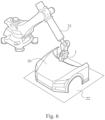
- the numerical control machine comprises a motorized arm 23 to support the supplying head 1 mentioned above at a respective end portion.
- the motorized arm 23 which is not described or shown in detail since of the known type, is adapted to move the head in the three spatial axes, by orienting the supplying head according to any position with respect to the object 20 and with respect to a supporting surface 22 onto which the object 20 is positioned during the printing process.
- the supporting surface 22, which is arranged under the supplying head 1, can in turn be moved close to/away from the supplying head 1.
- the coupling unit 2 is a device able to deliver a determined quantity of resin powder and to make it adhere to the filiform element 4.
- the quantity of powder delivered is in the ratio of 30% to 70% by volume with respect to the fiber of the filiform element 4 itself.
- Coupling units 2 adapted for the purpose can be represented by spraying members able to spray the resin powder on the filiform element 4 or by members containing a quantity of resin powder dispersed in a liquid through which the filiform element 4 passes.
- the energy source 6 is positioned downstream of the coupling unit 2.
- the energy source 6 can consist of a heat emitting source provided to heat the prepreg filiform element 4' downstream of the coupling unit 2, this in particular whenever powder such as a thermo-activatable resin powder is used for the matrix.
- the energy sources 6 of this type are generally based on the supply of a hot air flow or a laser source.
- the energy source 6 can be a radiation emitter.
- the energy source 6 can for example consist of at least one LED or IR emitter, or laser emitter, or any other radiation source, and is positioned in the supplying head 1 directly downstream of the coupling unit 2 and upstream of the delivery nozzle 8 for delivering the filiform element 3 or a derivative thereof.
- a cutting member 7 which can be represented by at least one movable blade 7' movable close to/away from each other to cut the filiform composite material 4".
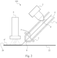
- FIG. 1 An alternative embodiment of the equipment 100 for the three-dimensional printing of continuous fiber composite materials according to the present invention and quite similar to the embodiment of figure 1 , except for the fact that the energy source 6 is positioned downstream of the coupling unit 2 and of the cutting member 7, is shown in figure 2 .
- the energy source 6 is also positioned downstream of the delivery nozzle 8 so as to polymerize the prepreg filiform element 4' after its deposition onto the supporting surface 22.
- FIG. 5 An alternative embodiment of the equipment 100 for the three-dimensional printing of continuous fiber composite materials according to the present invention and quite similar to the embodiment of figure 2 is shown in figure 5 , in this case, the coupling unit 2 is still arranged inside the supplying head 1, but is made of a bath containing a determined quantity of dispersed powder 5 appropriate for making a composite material matrix.
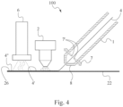
- FIG. 4 An alternative embodiment of the equipment 100 for the three-dimensional printing of continuous fiber composite materials according to the present invention is shown in figure 4 , wherein both the coupling unit 2 and the energy source 6 to polymerize the prepreg filiform element 4' are arranged outside and downstream of the supplying head 1.
- FIG. 3 An alternative embodiment of the equipment 100 for the three-dimensional printing of continuous fiber composite materials according to the present invention is shown in figure 3 , wherein the prepreg filiform element 4' is made upstream of the supplying head 1 and stored on a storage reel 14.
- the equipment 100 comprises a preparation station 17 to prepare the prepreg filiform element 4' arranged upstream of the supplying head 1.
- the filiform element 4, unwound from an appropriate reel 13, is first led, through a path guided by couples of rollers 15, 16, at the coupling unit 2 and subsequently at an energy source 6' where it is administered a determined quantity of energy.
- the quantity of energy applied to the prepreg element 4' does not polymerize it, but is used to better make the resin powder stick to the continuous filiform element 4.
- the preparation station 17 comprises a storage reel 14 downstream of the couples of rollers 15, 16.
- the prepreg filiform element 4' is sent from the storage reel 14 to the supplying head 1 to be deposited onto the supporting surface 22.
- a second energy source 6, configured to deliver a determined quantity of energy to the filiform composite material 4", preferably heat and adapted to polymerize and thus transform it into the filiform composite material 4", is placed downstream of the supplying head 1.
- the filiform composite material 4" is made discontinuously, the printing method in this case comprises a first process wherein the filiform element 4 is transformed into a prepreg filiform element 4' upstream of the supplying head 1 and preferably wound on a storage reel 14 and a second process wherein the prepreg filiform element 4' is sent to the supplying head 1 to be deposited.
- the supplying head 1 is advantageously supported by respective means for the relative movement between the supplying head 1 itself and the three-dimensional object 20 to be printed.
- the movement means exerts a traction force onto the filiform element 4 and, thus, also on the continuous fiber 3 contained therein.
- the relative movement between the supplying head 1 and the object 20 to be printed determines a traction action on the filiform composite material 4" during the respective deposition.
- this traction force causes the supply of the filiform element 4 itself into the supplying head.
- the movement means 18 comprise at least one machine numerically controlled moved on at least three axes.
- the numerical control machine comprises a motorized arm to support the supplying head 1 mentioned above at a respective end portion.
- the motorized arm 23 which is not described or shown in detail since of the known type, is adapted to move the head in the three spatial axes, by orienting the supplying head according to any position with respect to the object 10 and with respect to a supporting surface 22 onto which the object 10 is positioned during the printing process.
- the supporting surface 22, which is arranged under the supplying head 1, can in turn be moved close to/away from the supplying head 1.
- the present invention further concerns a method for the three-dimensional printing of continuous fiber composite materials which comprises the steps of:
- the quantity of thermal energy such as to induce a phase change to the prepreg filiform element 4' from a solid state to a liquid state is a quantity of thermal energy such as to lead the prepreg element 4' or the powdered polymer arranged thereon to a melting temperature or greater than 0.7Tg, Tg being the glass transition temperature of the powder.
- This supply and deposition process is carried out by exerting a dragging force on the filiform element 4 achieved by means of the relative movement between the supplying head 1 and the three-dimensional object 20 to be printed.
- the filiform element 4 is deposited gradually so that to form the three-dimensional object 20 that is designed with the consequent supply of the filiform element 4 and continuous fibers contained therein.
- the continuous filiform element 4 or a derivative thereof coming out of the supplying nozzle 8 is initially spread on the respective supporting surface 22.
- the continuous filiform element 4 or a derivative thereof is suddenly melted and cooled or polymerized by the energy source 6 on the supporting surface 22 so that to define a fixing point 26 to fix the supporting element to the composite material 4".
- the end of the supporting element 4 or of a derivative thereof is fixed to the supporting surface 22.
- the transformation of the filiform element 4 into a composite material can occur at different points between the supplying head 1 and the supporting surface 22 depending on the type of equipment used.
- the transformation occurs by combining a quantity of material (resin), appropriate for making a matrix for composite material, in the form of powder, with the filiform element 4.
- the powder is selected among thermoplastic materials or thermosetting materials.
- thermoplastic materials adapted for the purpose can be Peek, Nylon, Polyethylene.
- the combining step occurs at the supplying head 1 and, in particular, inside it, as shown in figures 1 , 2 , 5 .
- the combining step occurs by spraying, the combining unit 2 thus sprays a determined quantity of material powder appropriate for making a matrix for composite material on the filiform element 4.
- the filiform element 4 takes on the name of prepreg filiform element 4', but still is not a composite material 4" since the polymerization of the powder did not occur or, basically, the material is not in its final form.
- the polymerization or melting occurs thanks to an energy source 6 able to deliver a determined quantity of energy, preferably heat, onto the prepreg filiform element 4'.
- This step still occurs upstream of the combining step described previously, but can occur inside the supplying head 1, such as for example shown in figure 1 , or outside the latter, such as for example shown in figures 2-5 .
- the energy source 6 is arranged outside the supplying head 1 and subjects the prepreg filiform element 4' to a determined quantity of energy contemporaneously and after having been deposited onto the supporting surface 22.
- the combining step preferably occurs by spraying and the filiform element 4 is sprayed with a determined quantity of powder of a material appropriate for constructing the matrix for a composite material, after having been deposited onto the supporting surface 22.
- the polymerization also occurs downstream of the supplying head 1, when the filiform element 4, now prepreg filiform element 4', is deposited onto the supporting surface 22.
- an end of the filiform element 4' coming out of the supplying head is constrained to the printing surface 22 at a fixing point, for example through polymerization or sudden lowering of the temperature of the filiform element at the molten state.
- the fixing point 26 thus formed allows the filiform element 4 or a derivative thereof to be arranged on the printing surface 22 according to a precise path and to design the object 20 to be printed, while the numerical control machine 19 is moving.
- the supplying head 1 is thus displaced by the numerical control machine 1 according to a predetermined path defining the object 20 to be printed.
- the filiform element or a derivative thereof is cut by the blades 7'.
- FIG. 3 An alternative embodiment of the method for the three-dimensional printing of continuous fiber composite materials according to the present invention is schematically shown in figure 3 .
- the combining step and the impregnation step occur upstream of the supplying head 1 and, generally, at a moment time-shifted with respect to the printing.
- the filiform element 4 is unwound by an appropriate reel 13 through a path guided by couples of rollers 15, 16 and is thus lead first at the combining unit 2, where a determined quantity of powder of an appropriate material for constructing the matrix for a composite material is preferably deposited thereon by spraying and subsequently at an energy source 6' where it is administered a determined quantity of energy.
- the quantity of energy administered through the energy source 6' is used to make the polymeric powder better adhere to the continuous filiform element 4 which has become a prepreg filiform element 4' at this point.
- the filiform element 4 is wound on a storage reel 14.
- the prepreg filiform element 4' is sent to the supplying head 1 to be deposited onto the supporting surface 22, thanks to the robotic arm.
- a second energy source 6 In order to make the composite material adhere to the fixing surface 22 and subsequently permanently transform the prepreg filiform element 4' into a filiform composite material 4", the same is subjected again by a second energy source 6 to a determined quantity of energy, preferably heat and able to induce a phase change to the prepreg filiform element 4' from the solid state to the liquid state.
- the filiform composite material 4" is made discontinuously, the printing method in this case comprises a first process wherein the filiform element 4 is transformed into a prepreg filiform element 4' upstream of the supplying head 1 and preferably wound on a storage reel 14 and a second process wherein the prepreg filiform element 4' is sent to the supplying head 1 to be deposited.
- Said first and second processes being temporally separate, i.e. occurring at two different times.
- the method in its various embodiments described above allows to make artifacts without necessarily performing a conventional linear "division,” i.e. the division of the object to be printed into layers in parallel with the printing surface.
- the material 2 gradually supplied to the head 8 is polymerized or melted and cooled and made to adhere to the other layers already deposited (in virtue of the adhesive characteristics of the resin), thus allowing the continuous designing action which affects the fibers contained.
- thermoplastic and thermosetting materials which are combined in the form of powder with the continuous filiform element 3, can be used.
Landscapes
- Engineering & Computer Science (AREA)
- Chemical & Material Sciences (AREA)
- Materials Engineering (AREA)
- Manufacturing & Machinery (AREA)
- Mechanical Engineering (AREA)
- Physics & Mathematics (AREA)
- Optics & Photonics (AREA)
- Robotics (AREA)
- Composite Materials (AREA)
- Treatment Of Fiber Materials (AREA)
Claims (13)
- Gerät (100) zum dreidimensionalen Drucken von Endlosfaser-Verbundwerkstoffen, umfassend:- einen Zuführkopf (1) zum Zuführen von mindestens einem aus Endlosfasern (4) bestehenden fadenförmigen Element, das mindestens eine Faser umfasst;- eine Bewegungsanordnung für die Relativbewegung zwischen dem Zuführkopf (1) und dem zu bedruckenden dreidimensionalen Objekt (20), um eine Zugkraft auf das endlose fadenförmige Element (4) auszuüben;- eine Kopplungseinheit (2), um eine Menge an Materialpulver für eine Verbundwerkstoffmatrix auf das fadenförmige Element (4) zu koppeln; wobei die Kopplungseinheit (2) zum Ablegen einer bestimmten Pulvermenge auf dem endlosen fadenförmigen Element (4) eingerichtet ist, um ein fadenförmiges Prepreg-Element (4') zu bilden;- eine Energiequelle (6) zum Herbeiführen eines Phasenwechsels des fadenförmigen Prepreg-Elements (4') vom festen Zustand in den flüssigen Zustand; wobei die Energiequelle (6) stromabwärts der Kupplungseinheit (2) angeordnet ist; dadurch gekennzeichnet, dass- die Kopplungseinheit (2) zumindest teilweise im Inneren des Zuführkopfes (1) untergebracht ist, so dass die Kopplung zwischen der bestimmten Pulvermenge und dem endlosen fadenförmigen Element (4) im Inneren des Zuführkopfes (1) stattfindet.
- Gerät (100) zum dreidimensionalen Drucken von Endlosfaser-Verbundwerkstoffen nach Anspruch 1, dadurch gekennzeichnet, dass die Energiequelle (6) derart eingerichtet ist, dass sie die Pulvermenge einer solchen Energiemenge aussetzt, dass die Pulvermenge auf eine Schmelztemperatur von 0,7 Tg oder höher gebracht wird, wobei Tg die Glasübergangstemperatur des Pulvermaterials ist, so dass das endlose fadenförmige Element (4) zumindest teilweise eingebettet wird.
- Gerät (100) zum dreidimensionalen Drucken von Endlosfaser-Verbundwerkstoffen nach einem der vorhergehenden Ansprüche 1 bis 2, dadurch gekennzeichnet, dass die Kopplungseinheit (2) zur Kombination der Pulvermenge mit dem endlosen fadenförmigen Element (4) durch Sprühen eingerichtet ist.
- Gerät (100) zum dreidimensionalen Drucken von Endlosfaser-Verbundwerkstoffen nach einem der vorhergehenden Ansprüche 1 bis 3, dadurch gekennzeichnet, dass die Kopplungseinheit (2) zum Kombinieren der Pulvermenge mit dem endlosen fadenförmigen Element (4) durch Dispersion eingerichtet ist.
- Gerät (100) zum dreidimensionalen Drucken von Endlosfaser-Verbundwerkstoffen nach Anspruch 1, dadurch gekennzeichnet, dass die Kopplungseinheit (2) in einer zugeordneten und stromaufwärts des Zuführkopfes (1) liegenden Station angeordnet ist, so dass die Kopplung zwischen der bestimmten Pulvermenge und dem endlosen fadenförmigen Element (4) in einem solchen Zeitraum erfolgt, der es erlaubt, dass sich die Pulvermenge derart auf dem fadenförmigen Element ablagert, dass sie auch die innersten Fasern beeinflusst.
- Gerät (100) für den dreidimensionalen Druck von Endlosfaser-Verbundwerkstoffen nach Anspruch 1, dadurch gekennzeichnet, dass die Energiequelle (6) zumindest teilweise im Inneren des Zuführkopfes (1) angeordnet ist.
- Verfahren zum dreidimensionalen Drucken von Endlosfaser-Verbundwerkstoffen, das mit der Vorrichtung nach einem der Ansprüche 1-6 implementiert wird und folgende Schritte umfasst- Zuführen zu einem Zuführkopf (1) mindestens eines endlosen fadenförmigen Elements (4), das mindestens eine Endlosfaser umfasst;- Kombinieren einer bestimmten Menge von Materialpulver für eine Matrix für Verbundwerkstoffe mit dem endlosen fadenförmigen Element (4), um das endlose fadenförmige Element (4) in ein fadenförmiges Prepreg-Element (4') umzuwandeln;- Beaufschlagen des fadenförmigen Prepreg-Elements (4') mit einer derartigen Menge an thermischer Energie zur Herbeiführung einer Phasenänderung des fadenförmigen Prepreg-Elements (4') vom festen Zustand in den flüssigen Zustand;- Ablegen des fadenförmigen Elements auf einer Trägerfläche (22) und Herbeiführen eines Phasenwechsels vom flüssigen Zustand in den festen Zustand.
- Verfahren zum dreidimensionalen Drucken von Endlosfaser-Verbundwerkstoffen nach Anspruch 7, dadurch gekennzeichnet, dass das Pulver der besagten Menge an Materialpulver für eine Matrix für Verbundwerkstoffe aus thermoplastischen Werkstoffen oder duroplastischen Werkstoffen ausgewählt wird.
- Verfahren zum dreidimensionalen Drucken von Endlosfaser-Verbundwerkstoffen nach Anspruch 7, gekennzeichnet durch folgende Schritte:- Erstellen eines dreidimensionalen Modells des zu druckenden Objekts;- Erzeugen der Ablegepfade eines Zuführkopfes (1);- Verfolgen der erzeugten Pfade durch den Zuführkopf (1) durch Abgabe des endlosen fadenförmigen Elements (4) auf eine Trägerfläche (22).
- Verfahren zum dreidimensionalen Drucken von Endlosfaser-Verbundwerkstoffen nach Anspruch 7, dadurch gekennzeichnet, dass die Schritte des Zuführens und Ablegens durch Ausüben einer Zugkraft auf das endlose fadenförmige Element (4) mittels einer Relativbewegung zwischen einem jeweiligen Zuführkopf (1) und einer Trägerfläche (22) oder dem dreidimensionalen Objekt (20) implementiert werden.
- Verfahren zum dreidimensionalen Drucken von Endlosfaser-Verbundwerkstoffen nach Anspruch 7, gekennzeichnet durch folgende Schritte:- Verteilen mindestens eines Endes des endlosen fadenförmigen Elements (4) oder seines Derivats auf einer entsprechenden Trägerfläche (22);- Herbeiführen mindestens einer Zustandsänderung durch Schmelzen und Abkühlen oder Polymerisieren des endlosen fadenförmigen Elements (4) oder eines Derivats davon auf der Trägerfläche (22), um einen Fixierpunkt zum Fixieren des endlosen fadenförmigen Elements (4) oder eines Derivats davon auf der Fläche (22) zu definieren;- Bewegen des Zuführkopfes (1) in Bezug auf den Fixierpunkt gemäß einem vorbestimmten Pfad, der das zu bedruckende Objekt definiert; und- sofortiges Schmelzen und Abkühlen und/oder Polymerisieren des fadenförmigen Prepreg-Elements (4') während des Schritts des Bewegens des Zuführkopfs (1) zum Stabilisieren des Verbundwerkstoffs (4") in einem festen Zustand.
- Verfahren zum dreidimensionalen Drucken von Endlosfaser-Verbundwerkstoffen nach Anspruch 7, dadurch gekennzeichnet, dass der fadenförmige Verbundwerkstoff (4") diskontinuierlich hergestellt wird, wobei das Verfahren einen ersten Prozess aufweist, bei dem das fadenförmige Element (4) stromaufwärts des Zuführkopfes (1) in ein fadenförmiges Prepreg-Element (4,) umgewandelt wird, und einen zweiten Prozess, bei dem das fadenförmige Prepreg-Element (4') dem Zuführkopf (1) zugeführt wird, um abgelegt zu werden.
- Verfahren zum dreidimensionalen Drucken von Endlosfaser- Verbundwerkstoff nach Anspruch 12, dadurch gekennzeichnet, dass der erste und der zweite Prozess zu zwei verschiedenen Zeitpunkten erfolgen.
Applications Claiming Priority (2)
| Application Number | Priority Date | Filing Date | Title |
|---|---|---|---|
| IT102019000015297A IT201900015297A1 (it) | 2019-08-30 | 2019-08-30 | Apparecchiatura e metodo per la stampa tridimensionale di materiali compositi a fibra continua |
| PCT/IB2020/058033 WO2021038503A1 (en) | 2019-08-30 | 2020-08-28 | Equipment and method for the three-dimensional printing of continuous fiber composite materials |
Publications (3)
| Publication Number | Publication Date |
|---|---|
| EP4021709A1 EP4021709A1 (de) | 2022-07-06 |
| EP4021709C0 EP4021709C0 (de) | 2025-05-21 |
| EP4021709B1 true EP4021709B1 (de) | 2025-05-21 |
Family
ID=69468963
Family Applications (1)
| Application Number | Title | Priority Date | Filing Date |
|---|---|---|---|
| EP20775071.2A Active EP4021709B1 (de) | 2019-08-30 | 2020-08-28 | Gerät und verfahren zum dreidimensionalen drucken von endlosfaser-verbundwerkstoffen |
Country Status (4)
| Country | Link |
|---|---|
| US (1) | US12202194B2 (de) |
| EP (1) | EP4021709B1 (de) |
| IT (1) | IT201900015297A1 (de) |
| WO (1) | WO2021038503A1 (de) |
Families Citing this family (4)
| Publication number | Priority date | Publication date | Assignee | Title |
|---|---|---|---|---|
| CN115139520B (zh) * | 2021-03-29 | 2024-11-12 | 碳塑科技股份有限公司 | 增材制造系统以及增材制造方法 |
| IT202300008037A1 (it) * | 2023-04-24 | 2024-10-24 | Moi Composites S R L | Apparecchiatura e processo per la stampa tridimensionale di materiali compositi |
| CN116713484A (zh) * | 2023-05-25 | 2023-09-08 | 浙江正向增材制造有限公司 | 高通量材料打印设备及方法 |
| CN117922002A (zh) * | 2024-02-28 | 2024-04-26 | 深圳云疆智造科技有限公司 | 一种复合材料增材制作方法及系统 |
Family Cites Families (11)
| Publication number | Priority date | Publication date | Assignee | Title |
|---|---|---|---|---|
| US5936861A (en) * | 1997-08-15 | 1999-08-10 | Nanotek Instruments, Inc. | Apparatus and process for producing fiber reinforced composite objects |
| US9511543B2 (en) | 2012-08-29 | 2016-12-06 | Cc3D Llc | Method and apparatus for continuous composite three-dimensional printing |
| US20140232035A1 (en) | 2013-02-19 | 2014-08-21 | Hemant Bheda | Reinforced fused-deposition modeling |
| US10953609B1 (en) * | 2013-03-22 | 2021-03-23 | Markforged, Inc. | Scanning print bed and part height in 3D printing |
| US9126367B1 (en) | 2013-03-22 | 2015-09-08 | Markforged, Inc. | Three dimensional printer for fiber reinforced composite filament fabrication |
| WO2014197732A2 (en) * | 2013-06-05 | 2014-12-11 | Markforged, Inc. | Methods for fiber reinforced additive manufacturing |
| US10953598B2 (en) * | 2016-11-04 | 2021-03-23 | Continuous Composites Inc. | Additive manufacturing system having vibrating nozzle |
| US10759114B2 (en) * | 2017-12-29 | 2020-09-01 | Continuous Composites Inc. | System and print head for continuously manufacturing composite structure |
| CN108372658A (zh) * | 2018-02-07 | 2018-08-07 | 华中科技大学 | 连续纤维增强复合材料及零件的选区熔化成形方法及设备 |
| CN108381924B (zh) * | 2018-03-05 | 2021-03-16 | 新疆大学 | 一种用于生物复合材料的3d打印喷头 |
| US11110654B2 (en) * | 2018-04-12 | 2021-09-07 | Continuous Composites Inc. | System and print head for continuously manufacturing composite structure |
-
2019
- 2019-08-30 IT IT102019000015297A patent/IT201900015297A1/it unknown
-
2020
- 2020-08-28 EP EP20775071.2A patent/EP4021709B1/de active Active
- 2020-08-28 WO PCT/IB2020/058033 patent/WO2021038503A1/en not_active Ceased
- 2020-08-28 US US17/753,190 patent/US12202194B2/en active Active
Also Published As
| Publication number | Publication date |
|---|---|
| US20220274331A1 (en) | 2022-09-01 |
| IT201900015297A1 (it) | 2021-03-02 |
| EP4021709A1 (de) | 2022-07-06 |
| EP4021709C0 (de) | 2025-05-21 |
| WO2021038503A1 (en) | 2021-03-04 |
| US12202194B2 (en) | 2025-01-21 |
Similar Documents
| Publication | Publication Date | Title |
|---|---|---|
| EP4021709B1 (de) | Gerät und verfahren zum dreidimensionalen drucken von endlosfaser-verbundwerkstoffen | |
| EP3548241B1 (de) | Automatisierte herstellung einer faserigen vorform | |
| CN111163921B (zh) | 通过3d打印制造由复合材料制成的制品的方法 | |
| JP6195933B2 (ja) | 繊維プリフォームを製造する方法 | |
| US20220184888A1 (en) | System and method for dispensing composite filaments for additive manufacturing | |
| JP6902812B2 (ja) | 物品の付加製造用プリントヘッド | |
| US20170341300A1 (en) | Additive Manufacturing Process Continuous Reinforcement Fibers And High Fiber Volume Content | |
| US20180370129A1 (en) | Apparatus and method for three-dimensional printing of continuous fibre composite materials | |
| US20090246468A1 (en) | Apparatus and method for making reactive polymer pre-pregs | |
| US10626235B2 (en) | Flexible composite prepreg materials | |
| KR102052383B1 (ko) | 수지 코팅된 방사상 필러 및 이를 제조하는 시스템 및 방법 | |
| US5476627A (en) | Composite molding process utilizing tackified fabric material | |
| JP7037542B2 (ja) | 繊維を処理する方法、繊維を処理するための設備及びそれによって得られる処理された繊維で作られたテープ | |
| US6447705B1 (en) | Tackifier application for resin transfer molding | |
| EP4069136B1 (de) | Verfahren zum herstellen einer verstärkungsstruktur für zahnprothesen in endlosfaser-verbundwerkstoffen | |
| AU2007222694A1 (en) | Method for producing reinforced placed structures | |
| JPH0569492A (ja) | 中空棒状体の製造方法 | |
| KR101914705B1 (ko) | 고분자 복합 재료를 활용한 3d 입체물 제조 로봇 시스템 | |
| US20170152355A1 (en) | Article Made by Additive Manufacturing with Continuous Fiber Reinforcements | |
| EP3441212B1 (de) | Additive herstellung von faser-vorformlingen | |
| WO2012130732A1 (de) | Verfahren zur herstellung eines prepregs und eines daraus erhältlichen organoblechs | |
| WO2024224269A1 (en) | Equipment and process for the three-dimensional printing of composite materials | |
| WO1999012716A1 (en) | Process for producing a hollow body of fibre-reinforced thermoplastic and an arrangement for carrying out the process | |
| WO2024224229A1 (en) | Equipment and process for three-dimensional printing composite materials | |
| CN114728441A (zh) | 用于制造未固化的近净形层片的装置和方法 |
Legal Events
| Date | Code | Title | Description |
|---|---|---|---|
| STAA | Information on the status of an ep patent application or granted ep patent |
Free format text: STATUS: UNKNOWN |
|
| STAA | Information on the status of an ep patent application or granted ep patent |
Free format text: STATUS: THE INTERNATIONAL PUBLICATION HAS BEEN MADE |
|
| PUAI | Public reference made under article 153(3) epc to a published international application that has entered the european phase |
Free format text: ORIGINAL CODE: 0009012 |
|
| STAA | Information on the status of an ep patent application or granted ep patent |
Free format text: STATUS: REQUEST FOR EXAMINATION WAS MADE |
|
| 17P | Request for examination filed |
Effective date: 20220224 |
|
| AK | Designated contracting states |
Kind code of ref document: A1 Designated state(s): AL AT BE BG CH CY CZ DE DK EE ES FI FR GB GR HR HU IE IS IT LI LT LU LV MC MK MT NL NO PL PT RO RS SE SI SK SM TR |
|
| DAV | Request for validation of the european patent (deleted) | ||
| DAX | Request for extension of the european patent (deleted) | ||
| STAA | Information on the status of an ep patent application or granted ep patent |
Free format text: STATUS: EXAMINATION IS IN PROGRESS |
|
| 17Q | First examination report despatched |
Effective date: 20240425 |
|
| GRAP | Despatch of communication of intention to grant a patent |
Free format text: ORIGINAL CODE: EPIDOSNIGR1 |
|
| STAA | Information on the status of an ep patent application or granted ep patent |
Free format text: STATUS: GRANT OF PATENT IS INTENDED |
|
| INTG | Intention to grant announced |
Effective date: 20250214 |
|
| GRAS | Grant fee paid |
Free format text: ORIGINAL CODE: EPIDOSNIGR3 |
|
| GRAA | (expected) grant |
Free format text: ORIGINAL CODE: 0009210 |
|
| STAA | Information on the status of an ep patent application or granted ep patent |
Free format text: STATUS: THE PATENT HAS BEEN GRANTED |
|
| AK | Designated contracting states |
Kind code of ref document: B1 Designated state(s): AL AT BE BG CH CY CZ DE DK EE ES FI FR GB GR HR HU IE IS IT LI LT LU LV MC MK MT NL NO PL PT RO RS SE SI SK SM TR |
|
| REG | Reference to a national code |
Ref country code: GB Ref legal event code: FG4D |
|
| REG | Reference to a national code |
Ref country code: CH Ref legal event code: EP |
|
| REG | Reference to a national code |
Ref country code: DE Ref legal event code: R096 Ref document number: 602020051681 Country of ref document: DE |
|
| REG | Reference to a national code |
Ref country code: IE Ref legal event code: FG4D |
|
| U01 | Request for unitary effect filed |
Effective date: 20250605 |
|
| U07 | Unitary effect registered |
Designated state(s): AT BE BG DE DK EE FI FR IT LT LU LV MT NL PT RO SE SI Effective date: 20250613 |
|
| U20 | Renewal fee for the european patent with unitary effect paid |
Year of fee payment: 6 Effective date: 20250826 |
|
| PG25 | Lapsed in a contracting state [announced via postgrant information from national office to epo] |
Ref country code: ES Free format text: LAPSE BECAUSE OF FAILURE TO SUBMIT A TRANSLATION OF THE DESCRIPTION OR TO PAY THE FEE WITHIN THE PRESCRIBED TIME-LIMIT Effective date: 20250521 |
|
| PG25 | Lapsed in a contracting state [announced via postgrant information from national office to epo] |
Ref country code: GR Free format text: LAPSE BECAUSE OF FAILURE TO SUBMIT A TRANSLATION OF THE DESCRIPTION OR TO PAY THE FEE WITHIN THE PRESCRIBED TIME-LIMIT Effective date: 20250822 Ref country code: NO Free format text: LAPSE BECAUSE OF FAILURE TO SUBMIT A TRANSLATION OF THE DESCRIPTION OR TO PAY THE FEE WITHIN THE PRESCRIBED TIME-LIMIT Effective date: 20250821 |
|
| PG25 | Lapsed in a contracting state [announced via postgrant information from national office to epo] |
Ref country code: PL Free format text: LAPSE BECAUSE OF FAILURE TO SUBMIT A TRANSLATION OF THE DESCRIPTION OR TO PAY THE FEE WITHIN THE PRESCRIBED TIME-LIMIT Effective date: 20250521 |
|
| PG25 | Lapsed in a contracting state [announced via postgrant information from national office to epo] |
Ref country code: HR Free format text: LAPSE BECAUSE OF FAILURE TO SUBMIT A TRANSLATION OF THE DESCRIPTION OR TO PAY THE FEE WITHIN THE PRESCRIBED TIME-LIMIT Effective date: 20250521 |
|
| PG25 | Lapsed in a contracting state [announced via postgrant information from national office to epo] |
Ref country code: RS Free format text: LAPSE BECAUSE OF FAILURE TO SUBMIT A TRANSLATION OF THE DESCRIPTION OR TO PAY THE FEE WITHIN THE PRESCRIBED TIME-LIMIT Effective date: 20250821 |
|
| PG25 | Lapsed in a contracting state [announced via postgrant information from national office to epo] |
Ref country code: IS Free format text: LAPSE BECAUSE OF FAILURE TO SUBMIT A TRANSLATION OF THE DESCRIPTION OR TO PAY THE FEE WITHIN THE PRESCRIBED TIME-LIMIT Effective date: 20250921 |
|
| PG25 | Lapsed in a contracting state [announced via postgrant information from national office to epo] |
Ref country code: SM Free format text: LAPSE BECAUSE OF FAILURE TO SUBMIT A TRANSLATION OF THE DESCRIPTION OR TO PAY THE FEE WITHIN THE PRESCRIBED TIME-LIMIT Effective date: 20250521 |
|
| PG25 | Lapsed in a contracting state [announced via postgrant information from national office to epo] |
Ref country code: CZ Free format text: LAPSE BECAUSE OF FAILURE TO SUBMIT A TRANSLATION OF THE DESCRIPTION OR TO PAY THE FEE WITHIN THE PRESCRIBED TIME-LIMIT Effective date: 20250521 |
|
| PG25 | Lapsed in a contracting state [announced via postgrant information from national office to epo] |
Ref country code: SK Free format text: LAPSE BECAUSE OF FAILURE TO SUBMIT A TRANSLATION OF THE DESCRIPTION OR TO PAY THE FEE WITHIN THE PRESCRIBED TIME-LIMIT Effective date: 20250521 |