EP4021138A1 - Betriebsverfahren eines relais-benutzergeräts für ein entferntes benutzergerät - Google Patents
Betriebsverfahren eines relais-benutzergeräts für ein entferntes benutzergerät Download PDFInfo
- Publication number
- EP4021138A1 EP4021138A1 EP20855310.7A EP20855310A EP4021138A1 EP 4021138 A1 EP4021138 A1 EP 4021138A1 EP 20855310 A EP20855310 A EP 20855310A EP 4021138 A1 EP4021138 A1 EP 4021138A1
- Authority
- EP
- European Patent Office
- Prior art keywords
- relay
- reconfiguration message
- pdu session
- information
- rrc
- Prior art date
- Legal status (The legal status is an assumption and is not a legal conclusion. Google has not performed a legal analysis and makes no representation as to the accuracy of the status listed.)
- Granted
Links
Images


Classifications
-
- H—ELECTRICITY
- H04—ELECTRIC COMMUNICATION TECHNIQUE
- H04W—WIRELESS COMMUNICATION NETWORKS
- H04W76/00—Connection management
- H04W76/30—Connection release
- H04W76/32—Release of transport tunnels
-
- H—ELECTRICITY
- H04—ELECTRIC COMMUNICATION TECHNIQUE
- H04W—WIRELESS COMMUNICATION NETWORKS
- H04W76/00—Connection management
- H04W76/20—Manipulation of established connections
- H04W76/27—Transitions between radio resource control [RRC] states
-
- H—ELECTRICITY
- H04—ELECTRIC COMMUNICATION TECHNIQUE
- H04W—WIRELESS COMMUNICATION NETWORKS
- H04W76/00—Connection management
- H04W76/30—Connection release
-
- H—ELECTRICITY
- H04—ELECTRIC COMMUNICATION TECHNIQUE
- H04W—WIRELESS COMMUNICATION NETWORKS
- H04W76/00—Connection management
- H04W76/10—Connection setup
- H04W76/11—Allocation or use of connection identifiers
-
- H—ELECTRICITY
- H04—ELECTRIC COMMUNICATION TECHNIQUE
- H04W—WIRELESS COMMUNICATION NETWORKS
- H04W76/00—Connection management
- H04W76/20—Manipulation of established connections
- H04W76/22—Manipulation of transport tunnels
-
- H—ELECTRICITY
- H04—ELECTRIC COMMUNICATION TECHNIQUE
- H04W—WIRELESS COMMUNICATION NETWORKS
- H04W88/00—Devices specially adapted for wireless communication networks, e.g. terminals, base stations or access point devices
- H04W88/02—Terminal devices
- H04W88/04—Terminal devices adapted for relaying to or from another terminal or user
-
- H—ELECTRICITY
- H04—ELECTRIC COMMUNICATION TECHNIQUE
- H04W—WIRELESS COMMUNICATION NETWORKS
- H04W92/00—Interfaces specially adapted for wireless communication networks
- H04W92/04—Interfaces between hierarchically different network devices
- H04W92/10—Interfaces between hierarchically different network devices between terminal device and access point, i.e. wireless air interface
-
- H—ELECTRICITY
- H04—ELECTRIC COMMUNICATION TECHNIQUE
- H04W—WIRELESS COMMUNICATION NETWORKS
- H04W92/00—Interfaces specially adapted for wireless communication networks
- H04W92/16—Interfaces between hierarchically similar devices
- H04W92/18—Interfaces between hierarchically similar devices between terminal devices
Definitions
- the present specification relates to mobile communications.
- LTE Long-Term Evolution
- LTE-A Long-Term Evolution-Advanced
- 5G fifth-generation
- the fifth-generation communication defined by the International Telecommunication Union (ITU) refers to providing a maximum data transmission speed of 20Gbps and a maximum transmission speed of 100Mbps per user in anywhere. It is officially called “IMT-2020” and aims to be released around the world in 2020.
- the fifth-generation mobile communication supports multiples numerologies (and/or multiple Subcarrier Spacings (SCS)) to support various 5G services. For example, if SCS is 15 kHz, wide area can be supported in traditional cellular bands, and if SCS is 30 kHz/60 kHz, dense-urban, lower latency, and wider carrier bandwidth can be supported. If SCS is 60 kHz or higher, bandwidths greater than 24.25 GHz can be supported to overcome phase noise.
- numerologies and/or multiple Subcarrier Spacings (SCS)
- SCS Subcarrier Spacings
- NR frequency band is defined as a frequency range of two types, i.e., FR1, FR2.
- FR1 is 410 MHz - 7125 MHz
- FR2 is 24250 MHz - 52600 MHz, meaning millimeter wave (mmW).
- mmW millimeter wave
- FR1 may mean “sub 6GHz range”.
- FR2 may mean “above 6GHz range”, and may be referred to as millimeter Wave (mmW).
- mmW millimeter Wave
- FR1 may include a band of 410 MHz to 7125 MHz as shown in Table 2 below. That is, FR1 may include a frequency band of above 6 GHz (or, 5850, 5900, 5925 MHz, etc.). For example, a frequency band of above 6 GHz (or, 5850, 5900, 5925 MHz, etc.) included in FR1 may include an unlicensed band. The unlicensed band may be used for various purposes, e.g., for communication for a vehicle (e.g., autonomous driving). [Table 2] Frequency Range designation Corresponding frequency range Subcarrier Spacing FR1 410MHz - 7125MHz 15, 30, 60kHz FR2 24250MHz - 52600MHz 60, 120, 240kHz
- the ITU suggests three usage scenarios, e.g., enhanced Mobile Broadband (eMBB), massive Machine Type Communication (mMTC), and Ultra-Reliable and Low Latency Communications (URLLC).
- eMBB enhanced Mobile Broadband
- mMTC massive Machine Type Communication
- URLLC Ultra-Reliable and Low Latency Communications
- URLLC relates to a usage scenario in which high reliability and low delay time are required.
- services like autonomous driving, automation, and virtual realities requires high reliability and low delay time (e.g., 1ms or less).
- a delay time of the current 4G (LTE) is statistically 21-43ms (best 10%), 33-75ms (median).
- the current 4G (LTE) is not sufficient to support a service requiring a delay time of 1ms or less.
- the eMBB relates to a usage scenario that requires a mobile ultra-wideband.
- FIG. 1 is a structural diagram of a next-generation mobile communication network.
- the 5G Core network may include various components, part of which are shown in FIG. 1 , including an Access and mobility Management Function (AMF) 41, a Session Management Function (SMF) 42, a Policy Control Function (PCF) 43, a User Plane Function (UPF) 44, an Application Function (AF) 45, a Unified Data Management (UDM) 46 and a Non-3GPP Interworking Function (N3IWF) 49.
- AMF Access and mobility Management Function
- SMF Session Management Function
- PCF Policy Control Function
- UPF User Plane Function
- AF Application Function
- UDM Unified Data Management
- N3IWF Non-3GPP Interworking Function
- a UE 10 is connected to a data network via the UPF 44 through a Next Generation Radio Access Network (NG-RAN).
- NG-RAN Next Generation Radio Access Network
- the UE 10 may be provided with a data service even through untrusted non-3GPP access, e.g., a Wireless Local Area Network (WLAN).
- non-3GPP access e.g., a Wireless Local Area Network (WLAN).
- WLAN Wireless Local Area Network
- the N3IWF 59 may be deployed.
- FIG. 2 is an exemplary diagram illustrating a predicted structure of a next generation mobile communication in terms of a node.
- the UE is connected to a Data Network (DN) through a NG-RAN.
- DN Data Network
- the Control Plane Function (CPF) node as shown may perform all or part of the Mobility Management Entity (MME) function of the fourth generation mobile communication, and all or a part of the control plane function of the Serving Gateway (S-GW) and the PDN-Gateway (P-GW) of the fourth generation mobile communication.
- the CPF node includes an Access and mobility Management Function (AMF) node and a Session Management Function (SMF).
- AMF Access and mobility Management Function
- SMF Session Management Function
- the User Plane Function (UPF) node as shown is a type of a gateway over which user data is transmitted and received.
- the UPF node may perform all or part of the user plane functions of the S-GW and the P-GW of the fourth generation mobile communication.
- PCF Policy Control Function
- the Application Function (AF) node refers to a server for providing various services to the UE.
- the Unified Data Management (UDM) node refers to a type of a server that manages subscriber information, such as a Home Subscriber Server (HSS) of 4th generation mobile communication.
- the UDM node stores and manages the subscriber information in the Unified Data Repository (UDR).
- UDM Unified Data Repository
- the Authentication Server Function (AUSF) node as shown authenticates and manages the UE.
- the Network Slice Selection Function (NSSF) node refers to a node for performing network slicing as described below.
- a UE can simultaneously access two data networks using multiple Protocol Data Unit (PDU) sessions.
- PDU Protocol Data Unit
- FIG. 3 is an exemplary diagram illustrating an architecture for supporting simultaneously access two data networks.
- FIG. 3 illustrates an architecture that allows the UE to simultaneously access two data networks using one PDU session.
- FIG. 4 is another exemplary diagram showing a structure of a radio interface protocol between a UE and a gNB
- the radio interface protocol is based on the 3GPP radio access network standard.
- the radio interface protocol is horizontally composed of a physical layer, a data link layer, and a network layer, and is vertically divided into a user plane for transmission of data information and a control plane for transfer of control signal (signaling).
- the protocol layers may be divided into L1 (first layer), L2 (second layer), and L3 layer (third layer) based on the lower three layers of the Open System Interconnection (OSI) reference model widely known in communication systems.
- OSI Open System Interconnection
- the first layer provides an information transfer service using a physical channel.
- the physical layer is connected to an upper medium access control layer through a transport channel, and data between the medium access control layer and the physical layer is transmitted through the transport channel.
- data is transmitted between different physical layers, that is, between the physical layers of a transmitting side and a receiving side through a physical channel.
- the second layer includes a Medium Access Control (MAC) layer, a Radio Link Control (RLC) layer, and a Packet Data Convergence Protocol (PDCP) layer.
- MAC Medium Access Control
- RLC Radio Link Control
- PDCP Packet Data Convergence Protocol
- the third layer includes Radio Resource Control (hereinafter abbreviated as RRC) layer.
- RRC Radio Resource Control
- the RRC layer is defined only in the control plane and is in charge of control of logical channels, transport channels, and physical channels related to configuration, reconfiguration and release of radio bearers.
- RB refers to a service provided by the second layer for data transfer between the UE and the E-UTRAN.
- the Non-Access Stratum (NAS) layer performs functions such as connection management (session management) and mobility management.
- the NAS layer is divided into a NAS entity for Mobility Management (MM) and a NAS entity for Session Management (SM).
- MM Mobility Management
- SM Session Management
- the SM signaling message is processed, that is, generated and processed, at an NAS-SM layer of the UE and SMF.
- the contents of the SM signaling message are not interpreted by the AMF.
- the RRC layer, the RLC layer, the MAC layer, and the PHY layer located below the NAS layer are collectively referred to as an Access Stratum (AS).
- AS Access Stratum
- a network system i.e., 5GC for next-generation mobile communication (i.e., 5G) also supports non-3GPP access.
- An example of the non-3GPP access is typically a WLAN access.
- the WLAN access may include both a trusted WLAN and an untrusted WLAN.
- AMF performs Registration Management (RM) and Connection Management (CM) for 3GPP access as well as non-3GPP access.
- RM Registration Management
- CM Connection Management
- D2D Device-to-Device
- any UE may operate as a relay UE.
- the relay UE and the remote UE share and use a Data Radio Bearer (DRB), even when the PDU session of the relay UE is deactivated, the relay UE must maintain the DRB for the remote UE. In this case, the NAS layer of the relay UE may not recognize whether the PDU session is deactivated.
- DRB Data Radio Bearer
- the core network considers the PDU session to be inactive, but the relay UE considers the PDU session to be still active, resulting in a state mismatch of the PDU session.
- an object of the present specification is to propose a method for solving the above-described problems.
- a disclosure of the present specification provides a method for a Relay User Equipment (UE) to operate for a Remote UE.
- the method may include receiving, by the Relay UE, a Radio Resource Control (RRC) reconfiguration message or an RRC connection reconfiguration message from a base station.
- RRC Radio Resource Control
- the RRC reconfiguration message or the RRC connection reconfiguration message may include identification information of a Data Radio Bearer (DRB) shared with the Remote UE and information on a Protocol Data Unit (PDU) session to be deleted or released in the DRB.
- DRB Data Radio Bearer
- PDU Protocol Data Unit
- the method may include delivering, by an Access Stratum (AS) layer of the Relay UE to a Non-Access Stratum (NAS) layer of the Relay UE, information that a User Plane (UP) connection of the PDU session is released, based on the received RRC reconfiguration message or the RRC connection reconfiguration message.
- AS Access Stratum
- NAS Non-Access Stratum
- UP User Plane
- a disclosure of the present specification provides a chipset mounted on a Relay User Equipment (UE).
- the chipset may include at least one processor; and at least one memory for storing instructions and operably electrically connectable to the at least one processor.
- the instructions based on being executed by the at least one processor, may perform operations comprising: receiving, by the Relay UE, a Radio Resource Control (RRC) reconfiguration message or an RRC connection reconfiguration message from a base station.
- RRC reconfiguration message or the RRC connection reconfiguration message may include identification information of a Data Radio Bearer (DRB) shared with the Remote UE and information on a Protocol Data Unit (PDU) session to be deleted or released in the DRB.
- DRB Data Radio Bearer
- PDU Protocol Data Unit
- the operations may include delivering, by an Access Stratum (AS) layer of the Relay UE to a Non-Access Stratum (NAS) layer of the Relay UE, information that a User Plane (UP) connection of the PDU session is released, based on the received RRC reconfiguration message or the RRC connection reconfiguration message.
- AS Access Stratum
- NAS Non-Access Stratum
- UP User Plane
- the Relay UE may include a transceiver; at least one processor; and at least one memory for storing instructions and operably electrically connectable to the at least one processor.
- the instructions based on being executed by the at least one processor, may perform operations comprising: receiving, by the Relay UE, a Radio Resource Control (RRC) reconfiguration message or an RRC connection reconfiguration message from a base station.
- RRC Radio Resource Control
- the RRC reconfiguration message or the RRC connection reconfiguration message may include identification information of a Data Radio Bearer (DRB) shared with the Remote UE and information on a Protocol Data Unit (PDU) session to be deleted or released in the DRB.
- DRB Data Radio Bearer
- PDU Protocol Data Unit
- the operations may include delivering, by an Access Stratum (AS) layer of the Relay UE to a Non-Access Stratum (NAS) layer of the Relay UE, information that a User Plane (UP) connection of the PDU session is released, based on the received RRC reconfiguration message or the RRC connection reconfiguration message.
- AS Access Stratum
- NAS Non-Access Stratum
- UP User Plane
- a disclosure of the present specification provides a non-volatile computer-readable storage medium having recorded thereon instructions.
- the instructions when executed by one or more processors mounted, cause the one or more processors to perform operation comprising: receiving, by the Relay UE, a Radio Resource Control (RRC) reconfiguration message or an RRC connection reconfiguration message from a base station.
- RRC reconfiguration message or the RRC connection reconfiguration message may include identification information of a Data Radio Bearer (DRB) shared with the Remote UE and information on a Protocol Data Unit (PDU) session to be deleted or released in the DRB.
- DRB Data Radio Bearer
- PDU Protocol Data Unit
- the operations may include delivering, by an Access Stratum (AS) layer of the Relay UE to a Non-Access Stratum (NAS) layer of the Relay UE, information that a User Plane (UP) connection of the PDU session is released, based on the received RRC reconfiguration message or the RRC connection reconfiguration message.
- AS Access Stratum
- NAS Non-Access Stratum
- UP User Plane
- the term 'include' or 'have' may represent the existence of a feature, a number, a step, an operation, a component, a part or the combination thereof described in the present disclosure, and may not exclude the existence or addition of another feature, another number, another step, another operation, another component, another part or the combination thereof.
- first' and 'second' are used for the purpose of explanation about various components, and the components are not limited to the terms 'first' and 'second'.
- the terms 'first' and 'second' are only used to distinguish one component from another component.
- a first component may be named as a second component without deviating from the scope of the present disclosure.
- a or B may mean “only A”, “only B”, or “both A and B”.
- a or B in the present disclosure may be interpreted as “A and/or B”.
- A, B or C in the present disclosure may mean “only A”, “only B”, “only C”, or "any combination of A, B and C”.
- slash (/) or comma (,) may mean “and/or”.
- A/B may mean “A and/or B”.
- A/B may mean "only A”, “only B”, or “both A and B”.
- A, B, C may mean "A, B or C”.
- At least one of A and B may mean “only A”, “only B” or “both A and B”.
- the expression “at least one of A or B” or “at least one of A and/or B” in the present disclosure may be interpreted as same as “at least one of A and B”.
- At least one of A, B and C may mean “only A”, “only B”, “only C”, or “any combination of A, B and C”.
- at least one of A, B or C or “at least one of A, B and/or C” may mean “at least one of A, B and C”.
- parentheses used in the present disclosure may mean “for example”.
- control information PDCCH
- PDCCH PDCCH
- PDCCH PDCCH
- a User Equipment is illustrated by way of example, but the illustrated UE may also be referred to in terms of UE 100 (terminal), Mobile Equipment (ME), and the like.
- the UE may be a portable device such as a notebook computer, a mobile phone, a PDA, a smartphone, or a multimedia device or may be a non-portable device such as a PC or vehicle-mounted device.
- PDU Session Establishment procedure two different types of PDU Session Establishment procedures may exist as described below.
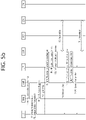
- FIGS. 5a and 5b are a signal flowchart illustrating an exemplary PDU session establishment procedure.
- the procedure shown in FIGS. 5a and 5b assumes that the UE has already registered on the AMF according to the registration procedure. Therefore, it is assumed that the AMF has already acquired user subscription data from UDM.
- the UE includes S-NSSAI from allowed NSSAI for the current access type. If information on the mapped NSSAI has been provided to the UE, the UE may provide both S-NSSAI based on the allowed NSSAI and the corresponding S-NSSAI based on the information on the mapped NSSAI.
- the information on the mapped NSSAI is information on mapping of each S-NSSAI in the allowed NSSAI to the S-NASSI in the NSSAI set up for Home Public Land Mobile Network (HPLMN).
- HPLMN Home Public Land Mobile Network
- the UE may extract and store the allowed NSSAI and the information on the mapped NSSAI, included in the registration accept message received from the network (i.e., AMF) in the registration procedure. Therefore, the UE may transmit by including both S-NSSAI based on the allowed NSSAI and the corresponding S-NSSAI based on the information on the mapped NSSAI in the PDU session establishment request message.
- the network i.e., AMF
- the UE may generate a new PDU session ID.
- the PDU Session Establishment procedure that is initiated by the UE may be started.
- the PDU Session Establishment Request message may include a Request type, an SSC mode, and a protocol configuration option.
- the Request type indicates "initial access”. However, in case an existing PDU session exists between the 3GPP access and the non-3GPP access, the Request type may indicate an "existing PDU session”.
- the NAS message being transmitted by the UE is encapsulated within an N2 message by the AN.
- the N2 message is transmitted to the AMF and may include user location information and access technique type information.
- the AMF may determine that the message corresponds to a request for a new PDU session.
- the AMF may determine default S-NSSAI for the requested PDU session according to the UE subscription.
- the AMF may relate a PDU session ID with an ID of the SMF and may store the PDU session ID.
- the AMF may select SMF.
- the AMF may transmit Nsmf_PDUSession_CreateSMContext Request message or Nsmf_PDUSession_UpdateSMContext Request message to the selected SMF.
- the Nsmf_PDUSession_CreateSMContext Request message may include SUPI, DNN, S-NSSAI(s), PDU Session ID, AMF ID, Request Type, PCF ID, Priority Access, N1 SM container, User location information, Access Type, PEI, GPSI, UE presence in LADN service area, Subscription For PDU Session Status Notification, DNN Selection Mode, and Trace Requirements.
- the SM container may include a PDU Session Establishment Request message.
- the Nsmf_PDUSession_UpdateSMContext Request message may include SUPI, DNN, S-NSSAI(s), SM Context ID, AMF ID, Request Type, N1 SM container, User location information, Access Type, RAT type, and PEI.
- the N1 SM container may include a PDU Session Establishment Request message.
- the AMF ID is used to identify the AMF serving the UE.
- the N1 SM information may include a PDU session establishment request message received from the UE.
- the SMF transmits a Subscriber Data Request message to the UDM.
- the Subscriber Data Request message may include a subscriber permanent ID and DNN.
- the UDM may transmit a Subscription Data Response message to the SMF.
- the SMF determines that the corresponding request is caused by a handover between the 3GPP access and the non-3GPP access.
- the SMF may identify the existing PDU session based on the PDU session ID.
- the SMF may request the subscription data.
- the subscription data may include an authenticated Request type, an authenticated SSC mode, and information on a default QoS profile.
- the SMF may verify whether or not the UE request follows the user subscription and local policy. Alternatively, the SMF may reject the UE request via NAS SM signaling (including the related SM rejection cause), which is forwarded (or transferred) by the AMF, and then the SMF may notify to the AMF that this shall be considered as a release of the PDU session ID.
- NAS SM signaling including the related SM rejection cause
- the SMF transmits Nsmf_PDUSession_CreateSMContext Response message or Nsmf_PDUSession_UpdateSMContext Response message to the AMF.
- the Nsmf_PDUSession_CreateSMContext Response message may include Cause, SM Context ID, or N1 SM container.
- the N1 SM container may include a PDU Session Reject.
- step 3 when the SMF has received the Nsmf_PDUSession_CreateSMContext Request message and the SMF can process the PDU Session establishment request message, the SMF creates SM context and the SM context ID is delivered to the AMF
- the SMF selects the PCF.
- the SMF performs an SM policy association establishment procedure in order to establish an SM policy association with the PCF.
- step 3 If the request type in step 3 indicates "initial request", the SMF selects the SSC mode for the PDU session. If step 5 is not performed, SMF may also select UPF. In case of the request type IPv4 or IPv6, the SMF may allocate an IP address/prefix for the PDU session.
- the SMF provides information on the policy control request trigger condition by performing the SM policy association modification procedure.
- the SMF may start the N4 session establishment procedure using the selected UPF, otherwise may start the N4 session modification procedure using the selected UPF.
- the SMF transmits an N4 Session Establishment/Modification request message to the UPF. And, the SMF may provide packet discovery, execution, and reporting rules of packets that are to be installed in the UPF for the PDU session. In case the SMF allocates CN tunnel information, the CN tunnel information may be provided to the UPF.
- the UPF may respond.
- the CN tunnel information may be provided to the SMF.
- the SMF transmits Namf_Communication_N1N2MessageTransfer message to the AMF.
- the Namf_Communication_N1N2MessageTransfer message may include PDU Session ID, N2 SM information, and N1 SM container.
- the N2 SM information may include PDU Session ID, QoS Flow ID (QFI), QoS Profile(s), CN Tunnel Info, S-NSSAI from the Allowed NSSAI, Session-AMBR, PDU Session Type, User Plane Security Enforcement information, UE Integrity Protection Maximum Data Rate.
- QFI QoS Flow ID
- QoS Profile(s) QoS Profile(s)
- CN Tunnel Info CN Tunnel Info
- S-NSSAI from the Allowed NSSAI Session-AMBR
- PDU Session Type User Plane Security Enforcement information
- UE Integrity Protection Maximum Data Rate UE Integrity Protection Maximum Data Rate
- the N1 SM container may include a PDU session establishment accept message.
- the PDU session establishment accept message may include an allowed QoS rule, SSC mode, S-NSSAI, and an assigned IPv4 address.
- the AMF transmits an N2 PDU Session Request message to the RAN.
- the message may include N2 SM information and an NAS message.
- the NAS message may include a PDU session ID and a PDU Session Establishment Accept message.
- the AMF may transmit an NAS message including a PDU session ID and a PDU Session Establishment Accept message. Additionally, the AMF may include the N2 SM information received from the SMF in the N2 PDU Session Request message and may then transmit the message including the N2 SM information to the RAN.
- the RAN may perform a specific signaling exchange with a UE being related to the information received from the SMF.
- the RAN also allocates RAN N3 tunnel information for the PDU session.
- the RAN forwards the NAS message, which is provided in the step 10.
- the NAS message may include a PDU session ID and N1 SM information.
- the N1 SM information may include a PDU Session Establishment Accept message.
- the RAN transmits the NAS message to the UE only in a case where a needed RAN resource is configured and allocation of RAN tunnel information is successful.
- the RAN transmits an N2 PDU Session Response message to the AMF.
- the message may include a PDU session ID, a cause, and N2 SM information.
- the N2 SM information may include a PDU session ID, (AN) tunnel information, and a list of allowed/rejected QoS profiles.
- the AMF may transmit Nsmf_PDUSession_UpdateSMContext Request message to the SMF.
- the Nsmf_PDUSession_UpdateSMContext Request message may include N2 SM information.
- the AMF may forward the N2 SM information received from the RAN to the SMF.
- the SMF may start an N4 Session Establishment procedure along with the UPF. Otherwise, the SMF may use the UPF to start an N4 Session Modification procedure.
- the SMF may provide AN tunnel information and CN tunnel information.
- the CN tunnel information shall be provided only in a case where the SMF selects the CN tunnel information in the step 8.
- the UPF may transmit an N4 Session Modification Response message to the SMF.
- the SMF transmits Nsmf_PDUSession_UpdateSMContext Response message to the AMF.
- the AMF can deliver the related event to the SMF.
- the SMF transmits Nsmf_PDUSession_SMContextStatusNotify message.
- the SMF transmits information to the UE through the UPF. More specifically, in case of PDU Type IPv6, the SMF may generate an IPv6 Router Advertisement and may transmit the generated advertisement to the UE through the N4 and UPF.
- the SMF During the procedure, if the PDU Session Establishment is not successful, the SMF notifies this to the AMF.
- FIGS. 6a and 6b show a modification procedure for a PDU session.
- the MA PDU session may be established/managed based on the PDU session modification procedure.
- the PDU session modification procedure may be initiated by the UE or may be initiated by the network.
- the UE may initiate a PDU session modification procedure by sending a NAS message.
- the NAS message may include an N1 SM container.
- the N1 SM container may include a PDU session modification request message, a PDU session ID, and information on the maximum data rate for integrity protection of the UE.
- the PDU session modification request message may include a PDU session ID, packet filters, requested QoS information, 5GSM core network capabilities, and the number of packet filters.
- the maximum data rate for integrity protection of the UE indicates the maximum data rate at which the UE can support UP integrity protection.
- the number of packet filters indicates the number of packet filters supported for QoS rules.
- the NAS message is transmitted to an appropriate AMF according to the location information of the UE via the RAN. Then, the AMF transmits an Nsmf PDUSession_UpdateSMContext message to the SMF.
- the message may include a Session Management (SM) context ID and an N1 SM container.
- the N1 SM container may include a PDU session modification request message.
- the PCF may inform the SMF of the policy change by initiating an SM policy association modification procedure.
- the UDM may update the subscription data of the SMF by transmitting a Nudm_SDM_Notification message.
- the SMF may update the session management subscriber data and transmit an ACK message to the UDM.
- SMF When initiated by SMF among network nodes, SMF may trigger QoS update.
- the SMF may perform a PDU session modification procedure.
- the AN may notify the SMF when an AN resource to which a QoS flow is mapped is released.
- the AN may transmit an N2 message to the AMF.
- the N2 message may include a PDU session ID and N2 SM information.
- the N2 SM information may include QoS Flow ID (QFI), user location information, and an indication indicating that the QoS flow is released.
- the AMF may transmit an Nsmf_PDUSession_UpdateSMContext message.
- the message may include SM context ID and N2 SM information.
- the SMF may transmit a report on the subscription event by performing the SM policy association modification procedure. If the PDU session modification procedure is triggered by 1b or Id, this step may be skipped. If a dynamic PCC is not deployed in the network, the SMF may apply an internal policy to decide to change the QoS profile.
- Steps 3 to 7, which will be described later, may not be performed when the PDU session modification requires only the UPF operation.
- the SMF may respond to the AMF by sending an Nsmf_PDUSession_UpdateSMContext message.
- the message may include N2 SM information and an N2 SM container.
- the N2 SM information may include a PDU session ID, QFI, QoS profile, and session-AMBR.
- the N1 SM container may include a PDU session modification command.
- the PDU session modification command may include a PDU session ID, a QoS rule, a QuS rule operation, QoS flow level QoS parameters, and a session-AMBR.
- the N2 SM information may include information to be transmitted by the AMF to the AN.
- the N2 SM information may include a QFI and a QoS profile to notify the AN that one or more QoS flows are added or modified. If the PDU session modification is requested by the UE for which the user plane resource is not configured, the N2 SM information to be delivered to the AN may include information on the establishment of the user plane resource.
- the N1 SM container may include a PDU session modification command to be delivered by the AMF to the UE.
- the PDU session modification command may include QoS rules and QoS flow level QoS parameters.
- the SMF may transmit a Namf_Communication_N1N2MessageTransfer message.
- the message may include N2 SM information and N1 SM container.
- the N2 SM information may include a PDU session ID, QFI, QoS profile, and session-AMBR.
- the N1 SM container may include a PDU session modification command.
- the PDU session modification command may include a PDU session ID, a QoS rule, and a QoS flow level QoS parameters.
- the AMF updates and stores the UE context based on the Namf_Communication_N1N2MessageTransfer message, and then steps 3 to 7 described later may be skipped.
- the AMF may transmit an N1 message to synchronize the UE context with the UE.
- the AMF may transmit an N2 PDU session request message to the AN.
- the N2 PDU session request message may include N2 SM information received from the SMF and a NAS message.
- the NAS message may include a PDU session ID and an N1 SM container.
- the N1 SM container may include a PDU session modification command.
- the AN performs AN signaling exchange with the UE related to the information received from the SMF. For example, in the case of NG-RAN, in order to modify the necessary AN resources related to the PDU session, an RRC connection reconfiguration procedure may be performed with the UE.
- the AN transmits an N2 PDU session ACK message in response to the received N2 PDU session request.
- the N2 PDU session ACK message may include N2 SM information and user location information.
- the N2 SM information may include a list of accepted/rejected QFIs, AN tunnel information, and a PDU session ID.
- the AMF delivers the N2 SM information and user location information received from the AN to the SMF through the Nsmf_PDUSession_UpdateSMContext message. Then, the SMF delivers the Nsmf PDUSession_UpdateSMContext message to the AMF
- the SMF transmits an N4 session modification request message to the UPF to update the N4 session of the UPF included in the PDU session modification.
- the SMF updates the UL packet detection rule of the new QoS flow together with the UPF.
- the UE transmits a NAS message in response to receiving the PDU session modification command.
- the NAS message may include a PDU session ID and an N1 SM container.
- the N1 SM container may include a PDU session modification command ACK.
- the AN transmits the NAS message to the AMF.
- the AMF may deliver the N1 SM container and user location information received from the AN to the SMF through an Nsmf_PDUSession_UpdateSMContext message.
- the N1 SM container may include a PDU session modification command ACK.
- the SMF may deliver an Nsmf_PDUSession_UpdateSMContext response message to the AMF
- the SMF transmits an N4 session modification request message to the UPF to update the N4 session of the UPF included in the PDU session modification.
- the message may include an N4 session ID.
- the SMF may inform the PCF whether or not the PCC decision can be performed through the SM policy association modification procedure.
- the SMF may notify the requesting entity for user location information related to the change of the PDU session.
- FIG. 7 shows an RRC state
- the UE When an RRC connection is established between the RRC layer of the UE and the RRC layer of the NG-RAN (i.e., gNB), the UE is in the RRC_CONNECTED state, otherwise it is in the RRC_IDLE state.
- the RRC_INACTIVE state is additionally defined, and the UE in the RRC_INACTIVE state may release the connection to the base station while maintaining the connection to the core network.
- FIG. 8 shows a concept of Device to Device (D2D) communication.
- D2D communication Due to an increase in user requirements for a Social Network Service (SNS), communication between UEs at a physically close distance, i.e., Device to Device (D2D) communication, is required. In addition, in the case of UEs used for public safety, D2D communication may be used.
- SNS Social Network Service
- a method for directly communicating without intervention of a base station (gNB) 300 is being discussed.
- gNB base station
- UE#4 100-4 may serve as a relay for UE#5 100-5 and UE#6 100-6.
- UE#1 100-1 may serve as a repeater for UE#2 100-2 and UE#3 100-3 that are far away from the cell center.
- D2D communication is also called a Proximity Service (ProSe).
- ProSe Proximity Service
- a UE performing a proximity service is also referred to as a ProSe UE.
- a link between UEs used for the D2D communication is also called a sidelink.
- the physical channels used for the sidelink include the following.
- the SLSS includes a Primary Sidelink Synchronization Signal (PSLSS) and a Secondary Sidelink Synchronization Signal (SSLSS).
- PSLSS Primary Sidelink Synchronization Signal
- SSLSS Secondary Sidelink Synchronization Signal
- FIG. 9 shows an architecture of a UE-to-Network Relay.
- FIG. 10 shows a protocol stack for UE-to-Network Relay.
- UE-to-Network Relay supports the network connection of the remote UE.
- the PC5 link is the interface between the UE and the UE-to-Network Relay.
- the Uu link is the interface between the UE-to-Network Relay and the base station.
- the UE is considered a remote UE.
- Communication between the remote UE and the UE-to-Network Relay is performed as one-to-one direct communication.
- UE-to-Network Relay supported only one-hop, but recently, UE-to-Network Relay needs to be improved to support multi-hop.
- the activation of a UP connection of an existing PDU Session includes the activation of User Plane connection (i.e., data bearer and N3 tunnel) between the UE and a core network (CN).
- User Plane connection i.e., data bearer and N3 tunnel
- either UE or network-triggered service request procedure may support independent activation of UP connection of PDU session.
- UE-triggered service request procedure allows the re-activation of UP connection of PDU sessions, and may support independent activation of UP connection of PDU Session.
- a UE in the CM-CONNECTED state may perform a service request procedure to request the independent activation of the UP connection of PDU Sessions.
- Re-activation of UP connection of PDU Sessions by the network may be handled as follows:
- the PDU Session may be established as an always-on PDU Session.
- the deactivation of the UP connection of an PDU Session includes the corresponding data bearer and N3 tunnel to be deactivated.
- the UP connection of different PDU Sessions may be deactivated independently.
- the N9 tunnel may be preserved. If a PDU Session is an always-on PDU Session, the SMF may not deactivate a UP connection of PDU Session.
- FIG. 11 is an exemplary flowchart illustrating a procedure for a network to selectively deactivate a UP connection of a PDU session.
- the following procedure is used to deactivate UP connection for a PDU Session of a UE in CM-CONNECTED state.
- the SMF may not configure the UPF to report inactivity.
- Step 1 The SMF may determine that the UP connection of the PDU Session can be deactivated in following cases:
- the SMF may decide to release the UPF of N3 terminating point. In that case, the SMF proceeds with step 2 and step 3. Otherwise, if the SMF decides to keep the UPF of N3 terminating points, the SMF may proceed with step 4.
- the SMF may initiate an N4 Session Release procedure to release the intermediate UPF of N3 terminating point. If there are multiple intermediate UPFs, this step can be performed for each UPFs to be released.
- the SMF may initiate N4 Session Modification procedure to the UPF (i.e., N9 terminating point or PDU Session Anchor) connecting to the released UPF.
- Step 3 If the intermediate UPF(s) of N3 terminating point is released in step 2, the SMF initiates an N4 Session Modification procedure towards the UPF connecting to the released UPF, indicating the need to remove AN Tunnel Info for N3 tunnel of the corresponding PDU Session.
- the UPF connecting to the released UPF may buffer the DL packets for this PDU Session or drop the DL packets for this PDU session or forward the DL packets for this PDU session to the SMF, based on buffering instruction provided by the SMF.
- the SMF may notify the UPF connecting to the released UPF to discard downlink data for the PDU Sessions and/or to not provide further Data Notification messages.
- N4 Session Modification procedure may occur toward N3 terminating point.
- Step 4 If the UPF of N3 terminating point is not released in step 2, the SMF may initiate an N4 Session Modification procedure indicating the need to remove AN Tunnel Info for N3 tunnel of the corresponding PDU Session.
- the UPF may buffer the DL packets for this PDU Session or drop the DL packets for this PDU session or forward the DL packets for this PDU session to the SMF, based on buffering instruction provided by the SMF.
- the SMF may notify the UPF to discard downlink data for the PDU Sessions and/or to not provide further Data Notification messages.
- the SMF may transmit the Namf_Communication_N1N2MessageTransfer message to release the NG-RAN resources associated with the PDU Session.
- the message may include PDU Session ID, and N2 SM Information.
- the N2 SM Information may include N2 Resource Release Request.
- the N2 Resource Release Request may include PDU Session ID.
- the AMF may send the N2 PDU Session Resource Release Command including N2 SM information received from the SMF.
- the NG-RAN may issue NG-RAN specific signalling exchange (e.g., RRC Connection Reconfiguration) with the UE to release the NG-RAN resources related to the PDU Session received from the AMF.
- NG-RAN specific signalling exchange e.g., RRC Connection Reconfiguration
- the AS layer in the UE indicates it to the NAS layer.
- this step may be skipped.
- the NG-RAN and UE synchronize the released radio resources for the deactivated PDU Session.
- Step 8 The NG-RAN acknowledges the N2 PDU Session Resource Release Command to the AMF including N2 SM Resource Release Ack message.
- the N2 SM Resource Release Ack message may include User Location Information, Secondary RAT Usage Data.
- Step 9 The AMF transmits the Nsmf PDUSession_UpdateSMContext message to acknowledge the message in step 5.
- the Nsmf PDUSession_UpdateSMContext message may include N2 SM Information.
- the N2 SM Information may include Secondary RAT Usage Data.
- the Relay UE and the Remote UE establish their own PDU sessions with the network, respectively. That is, although the Remote UE receives a network connection service through the Relay UE, the Remote UE is able to exchange NAS messages with the network, thereby creating or modifying a PDU session, and also performing a service request procedure for reactivating the UP connection of the PDU session.
- the Relay UE may share and use a Uu Data Radio Bearer (DRB) with the Remote UE. That is, the DRB used by the Relay UE to transmit and receive its own traffic can also be used for the purpose of relaying the traffic of the Remote UE.
- DRB Uu Data Radio Bearer
- the AS layer of the UE transmits to the NAS layer that the UP connection is also released according to the deactivation. Accordingly, when the UE needs to re-use the PDU session in which the UP connection has been released, it may request an operation for activating the UP connection of the PDU session from the network.
- DRB Uu DRB
- a phenomenon may occur in which the Relay UE, in particular, the NAS layer of the Relay UE does not recognize whether the PDU session is deactivated.
- the core network considers the PDU session to be deactivated, but the Relay UE considers the PDU session to be still active, resulting in a state mismatch of the PDU session.
- it may cause a problem in that the Relay UE transmits traffic through the PDU session.
- Disclosures of the present specification propose a method of processing UP deactivation of a PDU session of a Relay UE in order to solve the above-described problem.
- UE User Equipment
- UE-to-Network Relay ProSe UE-to-Network Relay
- Relay Relay UE
- UE-NW Relay eRelay, eRelay UE, eRelay-UE, ProSe Relay, and ProSe Relay UE
- Remote UE eRemote UE, eRemote-UE, ProSe Remote UE, and ProSe Remote are used interchangeably.
- UP connection deactivation of a PDU session is used interchangeably with PDU session deactivation and UP deactivation of a PDU session.
- UP connection activation of a PDU session is used interchangeably with PDU session activation and UP activation of a PDU session.
- the method proposed in the present specification is applicable to various services, such as eMBB, Vehicle to Everything (V2X), Public Safety, Internet of Things (IoT), IIoT, and the like.
- eMBB Vehicle to Everything
- V2X Vehicle to Everything
- IoT Internet of Things
- IIoT IIoT
- PC5 may refer to only NR PC5, or may refer to both NR PC5 and LTE PC5.
- NG-RAN may refer to only gNB or both gNB and ng-eNB.
- the method for processing the PDU session deactivation of the Relay UE proposed in the present specification consists of a combination of one or more of the following operations/configurations/steps.
- FIGS. 12a and 12b are exemplary signal flow diagrams illustrating a procedure according to one disclosure of the present specification.
- the UE-2 since the UE-2 requires a network connection service, after selecting the UE-1 as a UE-to-Network Relay, one-to-one direct communication can be assumed to have been established. That is, it may be assumed that the UE-1 (i.e., Relay UE) and the UE-2 (i.e., Remote UE) establish a PC5 unicast link.
- the PC5 unicast link is used interchangeably with the unicast link, the second layer link, the layer-2 link, and the L2 link.
- the UE-1 and the UE-2 may interact with the network (e.g., for authentication/authorization).
- the serving AMF of each UE may obtain information (e.g., ID of the counterpart UE, temporary ID, etc.) of the counterpart UE and store the obtained information in the context of the serving UE.
- the serving AMF (AMF-2) of the UE-2 that is a Remote UE may store information of the UE-1 that is a Relay UE in a context for the UE-2.
- the information of the UE-1 includes a Subscription Permanent Identifier (SUPI), a 5G Globally Unique Temporary Identifier (5G-GUTI), a 5G-S-Temporary Mobile Subscriber Identity (5G-S-TMSI), 5G-TMSI, of the UE-1, and serving AMF information.
- SUPI Subscription Permanent Identifier
- 5G-GUTI 5G Globally Unique Temporary Identifier
- 5G-S-TMSI 5G-S-Temporary Mobile Subscriber Identity
- 5G-TMSI 5G-TMSI
- Step 1 UP connection of PDU session #1 created by the UE-1 is activated.
- the UP connection of the PDU session may be activated according to various procedures including the procedure below.
- Activating the UP connection of the PDU session involves the NG-RAN (i.e., gNB or ng-eNB) establishing a DRB with the UE.
- the NG-RAN i.e., gNB or ng-eNB
- the NG-RAN may perform an RRC reconfiguration procedure or an RRC connection reconfiguration procedure with the UE.
- the NG-RAN may perform an RRC connection reconfiguration procedure with the UE based on the N2 request message received from the AMF.
- the NG-RAN i.e., gNB or ng-eNB
- the NG-RAN may establish a DRB with the UE to support all QoS flows belonging to PDU Session #1 of the UE-1.
- an RRC reconfiguration message is used, and in the case of ng-eNB, an RRC connection reconfiguration message is used.
- a radioBearerConfig field is included in the RRC reconfiguration message to configure the DRB.
- [Table 3] RRC Reconfiguration Message radioBearerConfig Field DRB-ToAddModList drb-Identity sdap-Config defaultDRB drb-ToReleaseList drb-Identity sdap-Config defaultDRB
- the defaultDRB indicates whether a default DRB is used for a PDU session.
- DRB-ToAddModList is included in the above.
- DRB-ToAddMod may be included in the form below.
- IE main Information Element
- DRB-ToAddModList and DRB-ToAddMod are used, a new IE may be defined and used for a PDU session of a UE operating as a Relay UE, or an existing IE may be modified/extended and used. For example, information informing that it is for the Relay UE itself may be explicitly or implicitly included in DRB-ToAddMod. Alternatively, information informing that the DRB may be shared between the Relay UE and the Remote UE may be explicitly or implicitly included.
- the UE-1 configures the DRB for PDU Session #1 based on the DRB configuration information provided by the NG-RAN (i.e., gNB or ng-eNB).
- the NG-RAN i.e., gNB or ng-eNB.
- the UE-1 and the NG-RAN i.e., gNB or ng-eNB store information/context for the established DRB.
- Step 2 The UP connection of PDU session #2 generated by the UE-2 (i.e., Remote UE) is activated.
- the NG-RAN i.e., gNB or ng-eNB
- the NG-RAN i.e., gNB or ng-eNB
- the NG-RAN i.e., gNB or ng-eNB
- the NG-RAN needs to add/modify/update DRB for PDU session #2 of the UE-2 to UE-1.
- the NG-RAN i.e., gNB or ng-eNB
- the UE-2 is receiving network connection services via the UE-1 (i.e., Relay UE) through RRC connection establishment with the UE-2 (i.e., Remote UE)
- the QoS characteristics e.g., when QoS characteristics are the same/similar to share a DRB
- the NG-RAN ie.., gNB or ng-eNB
- the UE-1 i.e., Relay UE
- the RRC configuration message may be extended and used, or a new RRC message may be defined and used.
- the new RRC message may be for configuring DRB/Signaling Radio Bearer (SRB)/RRC for the UE-2 (i.e., Remote UE) to the UE-1 (i.e., Relay UE).
- SRB DRB/Signaling Radio Bearer
- RRC Radio Bearer
- the DRB-ToAddModList may be modified/extended in the RRC Configuration message and used, or a new IE may be defined and used.
- the DRB configuration information provided to the Relay UE may explicitly or implicitly include information indicating that it is for the Remote UE.
- a new IE e.g., DRB-ToAddModList-forRemoteUE
- the NG-RAN i.e., gNB or ng-eNB
- the UE-1 i.e., Relay UE
- the DRB supports one QoS flow of PDU session #1 of the UE-1 (i.e., Relay UE) and two QoS flows of PDU session #2 of the UE-2 (i.e., Remote UE).
- the purpose is to inform the Relay UE (i.e., UE-1) which DRB is to be modified/updated. So, this can be understood as appropriately providing necessary information so that the Relay UE (i.e., UE-1) can perform DRB configuration based thereon.
- the UE-1 i.e., Relay UE
- the NG-RAN i.e., gNB or ng-eNB
- the NG-RAN i.e., gNB or ng-eNB
- Step 3 The SMF determines that the UP connection of the PDU session #1 of the UE-1 (i.e., Relay UE) can be deactivated. For details on step 3, refer to step 1 of FIG. 11 .
- Steps 4-8 This will refer to steps 2 to 6 of FIG. 11 .
- the NG-RAN i.e., gNB or ng-eNB
- the NG-RAN i.e., gNB or ng-eNB transmits an RRC reconfiguration message or an RRC connection reconfiguration message.
- the NG-RAN i.e., gNB or ng-eNB
- the NG-RAN may provide the DRB-ToAddMod including the following main information in the DRB-ToAddModList of the RRC reconfiguration message or the RRC connection reconfiguration message.
- the NG-RAN i.e., gNB or ng-eNB
- may provide DRB-ToReleaseList ⁇ 1 ⁇ in an RRC reconfiguration message or an RRC connection reconfiguration message.
- the DRB configuration information of the NG-RAN may be implicitly or explicitly include information informing that the DRB is shared between the Relay UE (i.e., UE-1) and the Remote UE (i.e., UE-2).
- the UE-1 i.e., Relay UE
- the UE-1 may determine that the DRB has been released/removed for itself.
- the AS layer of the UE-1 i.e., Relay UE
- the NAS layer informs the NAS layer that the UP connection of the PDU session #1 (which is its own PDU session #1) is released (or provides information informing this). For this reason, when the UE-1 (i.e., Relay UE) needs to use PDU session #1 in the future, a request for activating the UP connection for PDU session #1 may be performed to the network.
- DRB-ToAddModList and DRB-ToAddMod or the existing DRB-ToReleaseList are used, for a PDU session of the UE-1 operating as a Relay UE, a new IE may be defined and used, or an existing IE may be modified/extended and used.
- a new IE may be defined and used, or an existing IE may be modified/extended and used.
- information informing that it is for the Relay UE itself may be explicitly or implicitly included in DRB-ToAddMod.
- information informing that it is for the Relay UE itself may be explicitly or implicitly included in the DRB-ToReleaseList.
- the UE-1 i.e., Relay UE
- the NG-RAN i.e., gNB or ng-eNB
- Step 10 The UE-1 (i.e., Relay UE) transmits an RRC Reconfiguration Complete message to respond to the RRC reconfiguration message of the NG-RAN (i.e., gNB or ng-eNB).
- NG-RAN i.e., gNB or ng-eNB
- Steps 11-12 This will refer to steps 8 to 9 of FIG. 11 .
- FIGS. 12a and 12b show that the SMF and UPF for PDU Session #1 of the UE-1 and the SMF and UPF for PDU Session #2 of the UE-2 are the same, but different SMFs may be used, and different UPFs may be used.
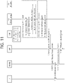
- FIG. 13 is an exemplary diagram illustrating an internal operation of the UE-1 (Relay UE) shown in FIGS. 12a and 12b .
- PDU session #1 of the UE-1 may be deleted from the DRB.
- the AS layer of the UE-1 i.e., Relay UE
- a request for activating the UP connection for PDU session #1 may be performed to the network.
- the DRB needs to be maintained for the Remote UE even though the PDU session of the Relay UE is deactivated. Accordingly, a phenomenon may occur in which the Relay UE, in particular, the NAS layer of the Relay UE does not recognize whether the PDU session is deactivated. Thereby, the core network considers the PDU session to be deactivated, but the Relay UE considers the PDU session to be still active, which may cause a PDU session state mismatch.
- the disclosure of the present specification ensures that there is no such mismatch state. That is, the disclosure of the present specification enables the NAS layer of the Relay UE to recognize that the PDU session is deactivated.
- FIG. 14 shows a block diagram of a processor in which the disclosure of the present specification is implemented.
- a processor 1020 in which the disclosure of the present specification is implemented may include a plurality of circuitry to implement the proposed functions, procedures and/or methods described herein.
- the processor 1020 may include a first circuit 1020-1, a second circuit 1020-2, and a third circuit 1020-3.
- the processor 1020 may include more circuits. Each circuit may include a plurality of transistors.
- the processor 1020 may be referred to as an Application-Specific Integrated Circuit (ASIC) or an Application Processor (AP), and includes at least one of a Digital Signal Processor (DSP), a Central Processing Unit (CPU), and a Graphics Processing Unit (GPU).
- ASIC Application-Specific Integrated Circuit
- AP Application Processor
- DSP Digital Signal Processor
- CPU Central Processing Unit
- GPU Graphics Processing Unit
- the processor may be a Relay UE or a Remote UE.
- the first circuit 1020-1 of the processor may receive a Radio Resource Control (RRC) reconfiguration message or an RRC connection reconfiguration message from a base station.
- RRC Radio Resource Control
- the RRC reconfiguration message or the RRC connection reconfiguration message may include identification information of a Data Radio Bearer (DRB) shared with the Remote UE and information on a Protocol Data Unit (PDU) session to be deleted or released in the DRB.
- DRB Data Radio Bearer
- PDU Protocol Data Unit
- the second circuit 1020-2 of the processor may deliver, by an Access Stratum (AS) layer of the Relay UE to a Non-Access Stratum (NAS) layer of the Relay UE, information that a User Plane (UP) connection of the PDU session is released, based on the received RRC reconfiguration message or the RRC connection reconfiguration message.
- AS Access Stratum
- NAS Non-Access Stratum
- UP User Plane
- the information on the PDU session to be deleted or released in the DRB may be information on a PDU session of the Relay UE.
- Data traffic of the Remote UE may be relayed through the DRB.
- the third circuit 1020-3 of the processor may transmit an RRC Reconfiguration Complete message in response to reception of the RRC reconfiguration message or the RRC connection reconfiguration message.
- a fourth circuit (not shown) of the processor may determine, by the Relay UE, to reuse the PDU session for itself.
- a fifth circuit (not shown) of the processor may transmit a service request message.
- a sixth circuit (not shown) of the processor may receive an RRC reconfiguration message or an RRC connection reconfiguration message to activate the UP connection of the PDU session.
- a seventh circuit (not shown) of the processor may establishe, by the Relay UE, one-to-one direct communication with the Remote UE.
- an eighth circuit (not shown) of the processor may receive an RRC reconfiguration message or an RRC connection reconfiguration message from the base station.
- the RRC reconfiguration message or the RRC connection reconfiguration message may include one or more of: identification information of the DRB, information informing that it is for the Remote UE, ID information of the Remote UE, or information on the PDU session of the Remote UE.
- FIG. 15 illustrates a wireless communication system according to an embodiment.
- the wireless communication system may include a first device 100a and a second device 100b.
- the first device 100a may be a UE described in the disclosure of the present specification.
- the first device 100a may be a base station, a network node, a transmission terminal, a reception terminal, a wireless device, a wireless communication device, a vehicle, a vehicle on which a self-driving function is mounted, a connected car, a drone (Unmanned Aerial Vehicle (UAV)), an Artificial Intelligence (AI) module, a robot, an Augmented Reality (AR) device, a Virtual Reality (VR) device, a Mixed Reality (MR) device, a hologram device, a public safety device, an MTC device, an IoT device, a medical device, a FinTech device (or financial device), a security device, a climate/environment device, a device related to 5G service or a device related to the fourth industrial revolution field.
- UAV Unmanned Aerial Vehicle
- AI Artificial Intelligence
- AR Augmented Reality
- VR Virtual Reality
- MR Mixed Reality
- hologram device
- the second device 100b may be a network node (e.g., AMF or MME) described in the disclosure of the present specification.
- the second device 100b may be a base station, a network node, a transmission terminal, a reception terminal, a wireless device, a wireless communication device, a vehicle, a vehicle on which a self-driving function is mounted, a connected car, a drone (Unmanned Aerial Vehicle (UAV)), an Artificial Intelligence (AI) module, a robot, an Augmented Reality (AR) device, a Virtual Reality (VR) device, a Mixed Reality (MR) device, a hologram device, a public safety device, an MTC device, an IoT device, a medical device, a FinTech device (or financial device), a security device, a climate/environment device, a device related to 5G service or a device related to the fourth industrial revolution field.
- UAV Unmanned Aerial Vehicle
- AI Artificial Intelligence
- AR Augmented Reality
- VR Virtual
- the UE may include a cellular phone, a smart phone, a laptop computer, a terminal for digital broadcasting, a Personal Digital Assistants (PDA), a Portable Multimedia Player (PMP), a navigation, a slate PC, a tablet PC, an ultrabook, a wearable device (e.g., a watch type terminal (smartwatch), a glass type terminal (smart glass), a Head Mounted Display (HMD)), and so on.
- the HMD may be a display device of a form, which is worn on the head.
- the HMD may be used to implement VR, AR or MR
- the drone may be a flight vehicle that flies by a wireless control signal without a person being on the flight vehicle.
- the VR device may include a device implementing the object or background of a virtual world.
- the AR device may include a device implementing the object or background of a virtual world by connecting it to the object or background of the real world.
- the MR device may include a device implementing the object or background of a virtual world by merging it with the object or background of the real world.
- the hologram device may include a device implementing a 360-degree stereographic image by recording and playing back stereographic information using the interference phenomenon of a light beam generated when two lasers called holography are met.
- the public safety device may include a video relay device or an imaging device capable of being worn on a user's body.
- the MTC device and the IoT device may be a device that does not require a person's direct intervention or manipulation.
- the MTC device and the IoT device may include a smart meter, a vending machine, a thermometer, a smart bulb, a door lock or a variety of sensors.
- the medical device may be a device used for the purpose of diagnosing, treating, reducing, handling or preventing a disease.
- the medical device may be a device used for the purpose of diagnosing, treating, reducing or correcting an injury or obstacle.
- the medical device may be a device used for the purpose of testing, substituting or modifying a structure or function.
- the medical device may be a device used for the purpose of controlling pregnancy.
- the medical device may include a device for medical treatment, a device for operation, a device for (external) diagnosis, a hearing aid or a device for a surgical procedure.
- the security device may be a device installed to prevent a possible danger and to maintain safety.
- the security device may be a camera, CCTV, a recorder or a blackbox.
- the FinTech device may be a device capable of providing financial services, such as mobile payment.
- the FinTech device may include a payment device or Point of Sales (PoS).
- the climate/environment device may include a device for monitoring or predicting the climate/environment.
- the first device 100a may include at least one processor such as a processor 1020a, at least one memory such as memory 1010a, and at least one transceiver such as a transceiver 1031a.
- the processor 1020a may perform the above-described functions, procedures, and/or methods.
- the processor 1020a may perform one or more protocols.
- the processor 1020a may perform one or more layers of a radio interface protocol.
- the memory 1010a is connected to the processor 1020a, and may store various forms of information and/or instructions.
- the transceiver 1031a is connected to the processor 1020a, and may be controlled to transmit and receive radio signals.
- the second device 100b may include at least one processor such as a processor 1020b, at least one memory device such as memory 1010b, and at least one transceiver such as a transceiver 1031b.
- the processor 1020b may perform the above-described functions, procedures and/or methods.
- the processor 1020b may implement one or more protocols.
- the processor 1020b may implement one or more layers of a radio interface protocol.
- the memory 1010b is connected to the processor 1020b, and may store various forms of information and/or instructions.
- the transceiver 1031b is connected to the processor 1020b and may be controlled transmit and receive radio signals.
- the memory 1010a and/or the memory 1010b may be connected inside or outside the processor 1020a and/or the processor 1020b, respectively, and may be connected to another processor through various technologies, such as a wired or wireless connection.
- the first device 100a and/or the second device 100b may have one or more antennas.
- an antenna 1036a and/or an antenna 1036b may be configured to transmit and receive radio signals.
- FIG. 16 illustrates a block diagram of a network node according to an embodiment.
- FIG. 16 is a diagram illustrating in detail a case in which a base station is divided into a Central Unit (CU) and a Distributed Unit (DU).
- CU Central Unit
- DU Distributed Unit
- base stations W20 and W30 may be connected to a core network W10.
- the base station W30 may be connected to a neighbor base station W20.
- an interface between the base stations W20 and W30 and the core network W10 may be referred to as an NG.
- An interface between the base station W30 and the neighbor base station W20 may be referred to as an Xn.
- the base station W30 may be divided into a CU W32 and DUs W34 and W36. That is, the base station W30 may be hierarchically divided and operated.
- the CU W32 may be connected to one or more DUs W34 and W36.
- an interface between the CU W32 and the DU W34, W36 may be referred to as an F1.
- the CU W32 may perform a function of higher layers of the base station.
- the DU W34, W36 may perform a function of lower layers of the base station.
- the CU W32 may be a logical node that hosts Radio Resource Control (RRC), Service Data Adaptation Protocol (SDAP) and Packet Data Convergence Protocol (PDCP) layers of the base station (e.g., gNB).
- RRC Radio Resource Control
- SDAP Service Data Adaptation Protocol
- PDCP Packet Data Convergence Protocol
- the DU W34, W36 may be a logical node that hosts Radio Link Control (RLC), Media Access Control (MAC) and physical (PHY) layers of the base station.
- RLC Radio Link Control
- MAC Media Access Control
- PHY physical
- the CU W32 may be a logical node that hosts RRC and PDCP layer of a base station (e.g., en-gNB).
- An operation of the DU W34, W36 may be partially controlled by the CU W32.
- the one DU W34, W36 may support one or more cells. One cell may be supported by only the one DU W34, W36.
- the one DU W34, W36 may be connected to the one CU W32, and the one DU W34, W36 may be connected to a plurality of CUs by a proper implementation.
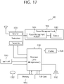
- FIG. 17 is a block diagram illustrating a configuration of a UE according to an embodiment.
- the UE 100 shown in FIG. 17 is a diagram illustrating the first device of FIG. 15 in more detail.
- a UE includes a memory 1010, a processor 1020, a transceiver 1031, a power management module 1091, a battery 1092, a display 1041, an input unit 1053, a speaker 1042, a microphone 1052, a Subscriber Identification Module (SIM) card, and one or more antennas.
- SIM Subscriber Identification Module
- the processor 1020 may be configured to implement the proposed function, process and/or method described in the present disclosure. Layers of a wireless interface protocol may be implemented in the processor 1020.
- the processor 1020 may include Application-Specific Integrated Circuit (ASIC), other chipset, logical circuit and/or data processing apparatus.
- the processor 1020 may be an Application Processor (AP).
- the processor 1020 may include at least one of a Digital Signal Processor (DSP), a Central Processing Unit (CPU), a Graphics Processing Unit (GPU) and a Modulator and Demodulator (Modem).
- DSP Digital Signal Processor
- CPU Central Processing Unit
- GPU Graphics Processing Unit
- Modulator and Demodulator Modem
- processor 1020 may be SNAPDRAGON TM series processor manufactured by Qualcomm ® , EXYNOS TM series processor manufactured by Samsung ® , A series processor manufactured by Apple ® , HELIO TM series processor manufactured by MediaTek ® , ATOM TM series processor manufactured by INTEL ® , or the corresponding next generation processor.
- the power management module 1091 manages a power for the processor 1020 and/or the transceiver 1031.
- the battery 1092 supplies power to the power management module 1091.
- the display 1041 outputs the result processed by the processor 1020.
- the input unit 1053 receives an input to be used by the processor 1020.
- the input unit 1053 may be displayed on the display 1041.
- the SIM card is an integrated circuit used to safely store International Mobile Subscriber Identity (IMSI) used for identifying a subscriber in a mobile telephoning apparatus such as a mobile phone and a computer and the related key. Many types of contact address information may be stored in the SIM card.
- IMSI International Mobile Subscriber Identity
- the memory 1010 is operably coupled with the processor 1020 and stores various types of information to operate the processor 1020.
- the memory may include Read-Only Memory (ROM), Random Access Memory (RAM), flash memory, a memory card, a storage medium, and/or other storage device.
- ROM Read-Only Memory
- RAM Random Access Memory
- flash memory a memory card
- storage medium e.g., hard disk drives
- a module may be stored in the memory 1010 and executed by the processor 1020.
- the memory may be implemented inside of the processor 1020.
- the memory 1010 may be implemented outside of the processor 1020 and may be connected to the processor 1020 in communicative connection through various means which is well-known in the art.
- the transceiver 1031 is operably connected to the processor 1020 and transmits and/or receives a radio signal.
- the transceiver 1031 includes a transmitter and a receiver.
- the transceiver 1031 may include a baseband circuit to process a radio frequency signal.
- the transceiver controls one or more antennas to transmit and/or receive a radio signal.
- the processor 1020 transfers command information to the transceiver 1031 to transmit a radio signal that configures a voice communication data.
- the antenna functions to transmit and receive a radio signal.
- the transceiver 1031 may transfer a signal to be processed by the processor 1020 and transform a signal in baseband. The processed signal may be transformed into audible or readable information output through the speaker 1042.
- the speaker 1042 outputs a sound related result processed by the processor 1020.
- the microphone 1052 receives a sound related input to be used by the processor 1020.
- a user inputs command information like a phone number by pushing (or touching) a button of the input unit 1053 or a voice activation using the microphone 1052.
- the processor 1020 processes to perform a proper function such as receiving the command information, calling a call number, and the like.
- An operational data on driving may be extracted from the SIM card or the memory 1010.
- the processor 1020 may display the command information or driving information on the display 1041 such that a user identifies it or for convenience.
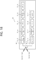
- FIG. 18 is a detailed block diagram illustrating the transceiver of the first device shown in FIG. 15 or the transceiver of the device shown in FIG. 17 in detail.
- the transceiver 1031 includes a transmitter 1031-1 and a receiver 1031-2.
- the transmitter 1031-1 includes a Discrete Fourier Transform (DFT) unit 1031-11, a subcarrier mapper 1031-12, an Inverse Fast Fourier Transform (IFFT) unit 1031-13 and a CP insertion unit 1031-14, and a radio transmitter 1031-15.
- the transmitter 1031-1 may further include a modulator.
- a scramble unit not shown
- a modulation mapper not shown
- a layer mapper not shown
- a layer permutator not shown
- the transmitter 1031-1 passes information through the DFT 1031-11 before mapping a signal to a subcarrier. After subcarrier mapping, by the subcarrier mapper 1031-12, of the signal spread (or precoded in the same sense) by the DFT unit 1031-11, a signal on the time axis is made through the IFFT unit 1031-13.
- PAPR Peak-to-Average Power Ratio
- the DFT unit 1031-11 outputs complex-valued symbols by performing DFT on input symbols. For example, when Ntx symbols are input (Ntx is a natural number), the DFT size is Ntx.
- the DFT unit 1031-11 may be referred to as a transform precoder.
- the subcarrier mapper 1031-12 maps the complex symbols to each subcarrier in the frequency domain. The complex symbols may be mapped to resource elements corresponding to resource blocks allocated for data transmission.
- the subcarrier mapper 1031-12 may be referred to as a resource element mapper.
- the IFFT unit 1031-13 outputs a baseband signal for data that is a time domain signal by performing IFFT on an input symbol.
- the CP insertion unit 1031-14 copies a part of the rear part of the baseband signal for data and inserts it in the front part of the baseband signal for data.
- ISI Inter-Symbol Interference
- ICI Inter-Carrier Interference
- the receiver 1031-2 includes a radio receiver 1031-21, a CP remover 1031-22, an FFT unit 1031-23, and an equalizer 1031-24, etc.
- the radio receiver 1031-21, the CP removing unit 1031-22, and the FFT unit 1031-23 of the receiver 1031-2 performs the reverse function of the radio transmitter 1031-15, the CP insertion unit 1031-14 and the IFFT unit 1031-13 of the transmitter 1031-1.
- the receiver 1031-2 may further include a demodulator.
- FIG. 19 illustrates a communication system 1 applied to the disclosure of the present specification.
- the communication system 1 applied to the disclosure of the present specification includes a wireless device, a base station, and a network.
- the wireless device refers to a device that performs communication using a radio access technology (e.g., 5G New RAT (NR)), Long-Term Evolution (LTE)), and may be referred to as a communication/wireless/5G device.
- NR 5G New RAT
- LTE Long-Term Evolution
- the wireless device may include a robot 100a, a vehicle 100b-1, 100b-2, an eXtended Reality (XR) device 100c, a hand-held device 100d, and a home appliance 100e, an Internet-of-Things (IoT) device 100f, and an AI device/server 400.
- a radio access technology e.g., 5G New RAT (NR)
- LTE Long-Term Evolution
- the wireless device may include a robot 100a, a vehicle 100b-1, 100b-2, an eXtended Reality (XR) device 100c,
- the vehicle may include a vehicle equipped with a wireless communication function, an autonomous driving vehicle, a vehicle capable of performing inter-vehicle communication, and the like.
- the vehicle may include an Unmanned Aerial Vehicle (UAV) (e.g., a drone).
- UAV Unmanned Aerial Vehicle
- XR devices include Augmented Reality (AR)/Virtual Reality (VR)/Mixed Reality (MR) devices, and may be implemented in the form of a Head-Mounted Device (HMD), a Head-Up Display (HUD) provided in a vehicle, a television, a smartphone, a computer, a wearable device, a home appliance, a digital signage, a vehicle, a robot, and the like.
- HMD Head-Mounted Device
- HUD Head-Up Display
- the hand-held device may include a smartphone, a smart pad, a wearable device (e.g., a smart watch, smart glasses), a computer (e.g., a laptop computer), and the like.
- Home appliances may include a TV, a refrigerator, a washing machine, and the like.
- the IoT device may include a sensor, a smart meter, and the like.
- the base station and the network may be implemented as a wireless device, and the specific wireless device 200a may operate as a base station/network node to other wireless devices.
- the wireless devices 100a to 100f may be connected to the network 300 via the base station 200.
- An Artificial Intelligence (AI) technology may be applied to the wireless devices 100a to 100f and the wireless devices 100a to 100f may be connected to the AI server 400 via the network 300.
- the network 300 may be configured using a 3G network, a 4G (e.g., LTE) network, a 5G (e.g., NR) network, and a beyond-5G network.
- the wireless devices 100a to 100f may communicate with each other through the base stations 200/network 300, the wireless devices 100a to 100f may perform direct communication (e.g., sidelink communication) with each other without passing through the BSs 200/network 300.
- the vehicles 100b-1 and 100b-2 may perform direct communication (e.g., Vehicle-to-Vehicle (V2V)/Vehicle-to-Everything (V2X) communication).
- the IoT device e.g., a sensor
- the IoT device may perform direct communication with other IoT devices (e.g., sensors) or other wireless devices 100a to 100f.
- Wireless communication/connections 150a, 150b and 150c may be established between wireless device 100a to 100f and base station 200, between base station 200/ base station 200.
- the wireless communication/connections may be established through various RATs (e.g., 5G NR) such as uplink/downlink communication 150a, sidelink communication (or Device-to-Device (D2D) communication) 150b, inter-base station communication 150c (e.g., relay, Integrated Access and Backhaul (IAB)), etc.
- the wireless devices 100a to 100f and the base station 200/the wireless devices 100a to 100f may transmit/receive radio signals to/from each other through the wireless communication/connections 150a, 150b and 150c.
- the wireless communication/connections 150a, 150b and 150c may transmit/receive signals through various physical channels.
- various configuration information configuring processes e.g., channel encoding/decoding, modulation/demodulation, and resource mapping/de-mapping
- resource allocating processes for transmitting/receiving radio signals, may be performed based on the various proposals of the present disclosure.
Landscapes
- Engineering & Computer Science (AREA)
- Computer Networks & Wireless Communication (AREA)
- Signal Processing (AREA)
- Mobile Radio Communication Systems (AREA)
- Radio Relay Systems (AREA)
Applications Claiming Priority (2)
| Application Number | Priority Date | Filing Date | Title |
|---|---|---|---|
| KR20190103122 | 2019-08-22 | ||
| PCT/KR2020/011168 WO2021034142A1 (ko) | 2019-08-22 | 2020-08-21 | 리모트 ue를 위한 릴레이 ue의 동작 방법 |
Publications (3)
| Publication Number | Publication Date |
|---|---|
| EP4021138A1 true EP4021138A1 (de) | 2022-06-29 |
| EP4021138A4 EP4021138A4 (de) | 2023-08-16 |
| EP4021138B1 EP4021138B1 (de) | 2024-07-10 |
Family
ID=74659743
Family Applications (1)
| Application Number | Title | Priority Date | Filing Date |
|---|---|---|---|
| EP20855310.7A Active EP4021138B1 (de) | 2019-08-22 | 2020-08-21 | Behandlung einer empfangenen rrc-verbindungsrekonfigurationsnachricht durch ein relais-ue |
Country Status (4)
| Country | Link |
|---|---|
| US (1) | US12219646B2 (de) |
| EP (1) | EP4021138B1 (de) |
| CN (1) | CN114586468B (de) |
| WO (1) | WO2021034142A1 (de) |
Cited By (1)
| Publication number | Priority date | Publication date | Assignee | Title |
|---|---|---|---|---|
| WO2024020728A1 (en) * | 2022-07-25 | 2024-02-01 | Lenovo (Beijing) Limited | Methods and apparatuses for simultaneous transmission on multiple paths |
Families Citing this family (6)
| Publication number | Priority date | Publication date | Assignee | Title |
|---|---|---|---|---|
| WO2022133977A1 (zh) * | 2020-12-25 | 2022-06-30 | Oppo广东移动通信有限公司 | 服务质量QoS控方法、终端设备和网络设备 |
| CN115175116A (zh) * | 2021-04-01 | 2022-10-11 | 维沃移动通信有限公司 | Pdu会话建立方法、相关设备及可读存储介质 |
| CN115734400A (zh) * | 2021-08-25 | 2023-03-03 | 华硕电脑股份有限公司 | 中继用户设备支持直接到间接通信路径切换的方法和设备 |
| US11601997B1 (en) * | 2021-08-25 | 2023-03-07 | Asustek Computer Inc. | Method and apparatus for a remote user equipment (UE) to support direct to indirect communication path switching in a wireless communication system |
| WO2023028940A1 (en) * | 2021-09-02 | 2023-03-09 | Apple Inc. | Communication coordination and reduced processing techniques for enhanced quality of service procedures |
| CN116209099A (zh) * | 2021-11-29 | 2023-06-02 | 华为技术有限公司 | 侧行链路通信方法和装置 |
Family Cites Families (13)
| Publication number | Priority date | Publication date | Assignee | Title |
|---|---|---|---|---|
| EP3142453B1 (de) * | 2015-09-08 | 2018-05-16 | ASUSTek Computer Inc. | Verfahren und vorrichtung zur auslösung einer funkträgerfreisetzung durch ein relais-ue (benutzergerät) in einem drahtloskommunikationssystem |
| WO2017099833A1 (en) | 2015-12-11 | 2017-06-15 | Intel IP Corporation | Control plane enhancements over sidelink for low power devices |
| CN108702722A (zh) * | 2016-02-17 | 2018-10-23 | Lg 电子株式会社 | 在无线通信系统中发送/接收位置注册有关消息的方法及其装置 |
| KR102201279B1 (ko) * | 2016-11-27 | 2021-01-11 | 엘지전자 주식회사 | 무선 통신 시스템에서의 등록 해제 방법 및 이를 위한 장치 |
| US10531420B2 (en) * | 2017-01-05 | 2020-01-07 | Huawei Technologies Co., Ltd. | Systems and methods for application-friendly protocol data unit (PDU) session management |
| JP2020036055A (ja) * | 2017-01-05 | 2020-03-05 | シャープ株式会社 | 端末装置、コアネットワーク装置、及び通信制御方法 |
| US10484517B2 (en) * | 2017-02-10 | 2019-11-19 | Qualcomm Incorporated | Quality of service support for layer 2 based device-to-device relay |
| AU2017406570B9 (en) * | 2017-03-31 | 2021-05-13 | Huawei Technologies Co., Ltd. | Relay communication method, apparatus and system |
| CN109151915B (zh) * | 2017-06-16 | 2023-11-17 | 夏普株式会社 | 用于数据分组递送的方法、用户设备和基站 |
| US11076317B2 (en) * | 2017-08-09 | 2021-07-27 | Nec Corporation | Radio access network node, core network node, radio terminal, and methods therefor |
| WO2019103462A1 (ko) * | 2017-11-21 | 2019-05-31 | 엘지전자 주식회사 | 무선 통신 시스템에서의 서비스 요청 방법 및 이를 위한 장치 |
| US10863390B2 (en) * | 2018-02-14 | 2020-12-08 | Mediatek Inc. | Method and apparatus for non-access stratum transport |
| MX2021005039A (es) * | 2018-10-31 | 2021-06-15 | Guangdong Oppo Mobile Telecommunications Corp Ltd | Metodo de indicacion de estado de sesion de la unidad de datos de protocolo, dispositivo terminal y medio de almacenamiento. |
-
2020
- 2020-08-21 CN CN202080073464.9A patent/CN114586468B/zh active Active
- 2020-08-21 EP EP20855310.7A patent/EP4021138B1/de active Active
- 2020-08-21 WO PCT/KR2020/011168 patent/WO2021034142A1/ko not_active Ceased
- 2020-08-21 US US17/636,295 patent/US12219646B2/en active Active
Cited By (2)
| Publication number | Priority date | Publication date | Assignee | Title |
|---|---|---|---|---|
| WO2024020728A1 (en) * | 2022-07-25 | 2024-02-01 | Lenovo (Beijing) Limited | Methods and apparatuses for simultaneous transmission on multiple paths |
| GB2634167A (en) * | 2022-07-25 | 2025-04-02 | Lenovo Beijing Ltd | Methods and apparatuses for simultaneous transmission on multiple paths |
Also Published As
| Publication number | Publication date |
|---|---|
| CN114586468A (zh) | 2022-06-03 |
| EP4021138A4 (de) | 2023-08-16 |
| US12219646B2 (en) | 2025-02-04 |
| CN114586468B (zh) | 2025-02-11 |
| EP4021138B1 (de) | 2024-07-10 |
| WO2021034142A1 (ko) | 2021-02-25 |
| US20220304099A1 (en) | 2022-09-22 |
Similar Documents
| Publication | Publication Date | Title |
|---|---|---|
| US11903057B2 (en) | Method for relaying unstructured traffic, and relay UE | |
| US12200595B2 (en) | Path-switching between PC5 link and UU link | |
| US12219626B2 (en) | Communication related to 3GPP PS data off | |
| EP4057657A1 (de) | Netzwerksteuerungsverfahren zum übertragen von ue-richtlinien | |
| EP4021138B1 (de) | Behandlung einer empfangenen rrc-verbindungsrekonfigurationsnachricht durch ein relais-ue | |
| EP4021075B1 (de) | Verfahren zum verschieben einer pdu-sitzung von einem nicht-3gpp- zu einem 3gpp-zugang | |
| US12003549B2 (en) | Method and terminal for processing security policy for V2X | |
| EP4090096A1 (de) | Kommunikation in zusammenhang mit mehreren usims | |
| EP4167620B1 (de) | Verfahren zur auslösung von smf zur effektiven durchführung einer redundanten übertragung durch verbesserung der funktion von nwdaf | |
| KR102850089B1 (ko) | 네트워크 슬라이스와 관련된 통신 | |
| US20230189208A1 (en) | Processing method of amf for supporting multiple usims | |
| US12150044B2 (en) | Scheme for selecting SMF node | |
| EP4156753A1 (de) | Verfahren zum betreiben von smf unter verwendung von analyseinformationen von nwdaf | |
| US20230189268A1 (en) | Operating method for user equipment supporting multiple usim | |
| KR20250114637A (ko) | 무선 통신 시스템에서 네트워크 슬라이싱의 다중 액세스 pdu 세션 처리 방법 및 장치 | |
| CN119605248A (zh) | 对用于工业用流量的信令或数据的接入控制机制 |
Legal Events
| Date | Code | Title | Description |
|---|---|---|---|
| STAA | Information on the status of an ep patent application or granted ep patent |
Free format text: STATUS: THE INTERNATIONAL PUBLICATION HAS BEEN MADE |
|
| PUAI | Public reference made under article 153(3) epc to a published international application that has entered the european phase |
Free format text: ORIGINAL CODE: 0009012 |
|
| STAA | Information on the status of an ep patent application or granted ep patent |
Free format text: STATUS: REQUEST FOR EXAMINATION WAS MADE |
|
| 17P | Request for examination filed |
Effective date: 20220208 |
|
| AK | Designated contracting states |
Kind code of ref document: A1 Designated state(s): AL AT BE BG CH CY CZ DE DK EE ES FI FR GB GR HR HU IE IS IT LI LT LU LV MC MK MT NL NO PL PT RO RS SE SI SK SM TR |
|
| DAV | Request for validation of the european patent (deleted) | ||
| DAX | Request for extension of the european patent (deleted) | ||
| A4 | Supplementary search report drawn up and despatched |
Effective date: 20230714 |
|
| RIC1 | Information provided on ipc code assigned before grant |
Ipc: H04W 92/18 20090101ALN20230710BHEP Ipc: H04W 92/10 20090101ALN20230710BHEP Ipc: H04W 88/04 20090101ALN20230710BHEP Ipc: H04W 76/22 20180101ALN20230710BHEP Ipc: H04W 76/11 20180101ALN20230710BHEP Ipc: H04W 76/32 20180101ALI20230710BHEP Ipc: H04W 80/10 20090101ALI20230710BHEP Ipc: H04W 76/30 20180101ALI20230710BHEP Ipc: H04W 76/14 20180101ALI20230710BHEP Ipc: H04W 76/27 20180101AFI20230710BHEP |
|
| REG | Reference to a national code |
Ref country code: DE Ref legal event code: R079 Free format text: PREVIOUS MAIN CLASS: H04W0076270000 Ipc: H04W0076320000 Ref document number: 602020033884 Country of ref document: DE |
|
| GRAP | Despatch of communication of intention to grant a patent |
Free format text: ORIGINAL CODE: EPIDOSNIGR1 |
|
| STAA | Information on the status of an ep patent application or granted ep patent |
Free format text: STATUS: GRANT OF PATENT IS INTENDED |
|
| RIC1 | Information provided on ipc code assigned before grant |
Ipc: H04W 92/18 20090101ALN20240206BHEP Ipc: H04W 92/10 20090101ALN20240206BHEP Ipc: H04W 88/04 20090101ALN20240206BHEP Ipc: H04W 76/22 20180101ALN20240206BHEP Ipc: H04W 76/11 20180101ALN20240206BHEP Ipc: H04W 80/10 20090101ALI20240206BHEP Ipc: H04W 76/30 20180101ALI20240206BHEP Ipc: H04W 76/14 20180101ALI20240206BHEP Ipc: H04W 76/27 20180101ALI20240206BHEP Ipc: H04W 76/32 20180101AFI20240206BHEP |
|
| INTG | Intention to grant announced |
Effective date: 20240219 |
|
| GRAS | Grant fee paid |
Free format text: ORIGINAL CODE: EPIDOSNIGR3 |
|
| GRAA | (expected) grant |
Free format text: ORIGINAL CODE: 0009210 |
|
| STAA | Information on the status of an ep patent application or granted ep patent |
Free format text: STATUS: THE PATENT HAS BEEN GRANTED |
|
| AK | Designated contracting states |
Kind code of ref document: B1 Designated state(s): AL AT BE BG CH CY CZ DE DK EE ES FI FR GB GR HR HU IE IS IT LI LT LU LV MC MK MT NL NO PL PT RO RS SE SI SK SM TR |
|
| REG | Reference to a national code |
Ref country code: CH Ref legal event code: EP |
|
| REG | Reference to a national code |
Ref country code: DE Ref legal event code: R096 Ref document number: 602020033884 Country of ref document: DE |
|
| REG | Reference to a national code |
Ref country code: LT Ref legal event code: MG9D |
|
| REG | Reference to a national code |
Ref country code: NL Ref legal event code: MP Effective date: 20240710 |
|
| PG25 | Lapsed in a contracting state [announced via postgrant information from national office to epo] |
Ref country code: PT Free format text: LAPSE BECAUSE OF FAILURE TO SUBMIT A TRANSLATION OF THE DESCRIPTION OR TO PAY THE FEE WITHIN THE PRESCRIBED TIME-LIMIT Effective date: 20241111 |
|
| REG | Reference to a national code |
Ref country code: AT Ref legal event code: MK05 Ref document number: 1703167 Country of ref document: AT Kind code of ref document: T Effective date: 20240710 |
|
| PG25 | Lapsed in a contracting state [announced via postgrant information from national office to epo] |
Ref country code: NL Free format text: LAPSE BECAUSE OF FAILURE TO SUBMIT A TRANSLATION OF THE DESCRIPTION OR TO PAY THE FEE WITHIN THE PRESCRIBED TIME-LIMIT Effective date: 20240710 |
|
| PG25 | Lapsed in a contracting state [announced via postgrant information from national office to epo] |
Ref country code: PT Free format text: LAPSE BECAUSE OF FAILURE TO SUBMIT A TRANSLATION OF THE DESCRIPTION OR TO PAY THE FEE WITHIN THE PRESCRIBED TIME-LIMIT Effective date: 20241111 Ref country code: NL Free format text: LAPSE BECAUSE OF FAILURE TO SUBMIT A TRANSLATION OF THE DESCRIPTION OR TO PAY THE FEE WITHIN THE PRESCRIBED TIME-LIMIT Effective date: 20240710 |
|
| PG25 | Lapsed in a contracting state [announced via postgrant information from national office to epo] |
Ref country code: NO Free format text: LAPSE BECAUSE OF FAILURE TO SUBMIT A TRANSLATION OF THE DESCRIPTION OR TO PAY THE FEE WITHIN THE PRESCRIBED TIME-LIMIT Effective date: 20241010 |
|
| PG25 | Lapsed in a contracting state [announced via postgrant information from national office to epo] |
Ref country code: FI Free format text: LAPSE BECAUSE OF FAILURE TO SUBMIT A TRANSLATION OF THE DESCRIPTION OR TO PAY THE FEE WITHIN THE PRESCRIBED TIME-LIMIT Effective date: 20240710 Ref country code: GR Free format text: LAPSE BECAUSE OF FAILURE TO SUBMIT A TRANSLATION OF THE DESCRIPTION OR TO PAY THE FEE WITHIN THE PRESCRIBED TIME-LIMIT Effective date: 20241011 Ref country code: PL Free format text: LAPSE BECAUSE OF FAILURE TO SUBMIT A TRANSLATION OF THE DESCRIPTION OR TO PAY THE FEE WITHIN THE PRESCRIBED TIME-LIMIT Effective date: 20240710 |
|
| PG25 | Lapsed in a contracting state [announced via postgrant information from national office to epo] |
Ref country code: BG Free format text: LAPSE BECAUSE OF FAILURE TO SUBMIT A TRANSLATION OF THE DESCRIPTION OR TO PAY THE FEE WITHIN THE PRESCRIBED TIME-LIMIT Effective date: 20240710 |
|
| PG25 | Lapsed in a contracting state [announced via postgrant information from national office to epo] |
Ref country code: LV Free format text: LAPSE BECAUSE OF FAILURE TO SUBMIT A TRANSLATION OF THE DESCRIPTION OR TO PAY THE FEE WITHIN THE PRESCRIBED TIME-LIMIT Effective date: 20240710 |
|
| PG25 | Lapsed in a contracting state [announced via postgrant information from national office to epo] |
Ref country code: IS Free format text: LAPSE BECAUSE OF FAILURE TO SUBMIT A TRANSLATION OF THE DESCRIPTION OR TO PAY THE FEE WITHIN THE PRESCRIBED TIME-LIMIT Effective date: 20241110 Ref country code: AT Free format text: LAPSE BECAUSE OF FAILURE TO SUBMIT A TRANSLATION OF THE DESCRIPTION OR TO PAY THE FEE WITHIN THE PRESCRIBED TIME-LIMIT Effective date: 20240710 |
|
| PG25 | Lapsed in a contracting state [announced via postgrant information from national office to epo] |
Ref country code: HR Free format text: LAPSE BECAUSE OF FAILURE TO SUBMIT A TRANSLATION OF THE DESCRIPTION OR TO PAY THE FEE WITHIN THE PRESCRIBED TIME-LIMIT Effective date: 20240710 |
|
| PG25 | Lapsed in a contracting state [announced via postgrant information from national office to epo] |
Ref country code: RS Free format text: LAPSE BECAUSE OF FAILURE TO SUBMIT A TRANSLATION OF THE DESCRIPTION OR TO PAY THE FEE WITHIN THE PRESCRIBED TIME-LIMIT Effective date: 20241010 Ref country code: ES Free format text: LAPSE BECAUSE OF FAILURE TO SUBMIT A TRANSLATION OF THE DESCRIPTION OR TO PAY THE FEE WITHIN THE PRESCRIBED TIME-LIMIT Effective date: 20240710 |
|
| PG25 | Lapsed in a contracting state [announced via postgrant information from national office to epo] |
Ref country code: RS Free format text: LAPSE BECAUSE OF FAILURE TO SUBMIT A TRANSLATION OF THE DESCRIPTION OR TO PAY THE FEE WITHIN THE PRESCRIBED TIME-LIMIT Effective date: 20241010 Ref country code: PL Free format text: LAPSE BECAUSE OF FAILURE TO SUBMIT A TRANSLATION OF THE DESCRIPTION OR TO PAY THE FEE WITHIN THE PRESCRIBED TIME-LIMIT Effective date: 20240710 Ref country code: NO Free format text: LAPSE BECAUSE OF FAILURE TO SUBMIT A TRANSLATION OF THE DESCRIPTION OR TO PAY THE FEE WITHIN THE PRESCRIBED TIME-LIMIT Effective date: 20241010 Ref country code: LV Free format text: LAPSE BECAUSE OF FAILURE TO SUBMIT A TRANSLATION OF THE DESCRIPTION OR TO PAY THE FEE WITHIN THE PRESCRIBED TIME-LIMIT Effective date: 20240710 Ref country code: IS Free format text: LAPSE BECAUSE OF FAILURE TO SUBMIT A TRANSLATION OF THE DESCRIPTION OR TO PAY THE FEE WITHIN THE PRESCRIBED TIME-LIMIT Effective date: 20241110 Ref country code: HR Free format text: LAPSE BECAUSE OF FAILURE TO SUBMIT A TRANSLATION OF THE DESCRIPTION OR TO PAY THE FEE WITHIN THE PRESCRIBED TIME-LIMIT Effective date: 20240710 Ref country code: GR Free format text: LAPSE BECAUSE OF FAILURE TO SUBMIT A TRANSLATION OF THE DESCRIPTION OR TO PAY THE FEE WITHIN THE PRESCRIBED TIME-LIMIT Effective date: 20241011 Ref country code: FI Free format text: LAPSE BECAUSE OF FAILURE TO SUBMIT A TRANSLATION OF THE DESCRIPTION OR TO PAY THE FEE WITHIN THE PRESCRIBED TIME-LIMIT Effective date: 20240710 Ref country code: ES Free format text: LAPSE BECAUSE OF FAILURE TO SUBMIT A TRANSLATION OF THE DESCRIPTION OR TO PAY THE FEE WITHIN THE PRESCRIBED TIME-LIMIT Effective date: 20240710 Ref country code: BG Free format text: LAPSE BECAUSE OF FAILURE TO SUBMIT A TRANSLATION OF THE DESCRIPTION OR TO PAY THE FEE WITHIN THE PRESCRIBED TIME-LIMIT Effective date: 20240710 Ref country code: AT Free format text: LAPSE BECAUSE OF FAILURE TO SUBMIT A TRANSLATION OF THE DESCRIPTION OR TO PAY THE FEE WITHIN THE PRESCRIBED TIME-LIMIT Effective date: 20240710 |
|
| REG | Reference to a national code |
Ref country code: CH Ref legal event code: PL |
|
| REG | Reference to a national code |
Ref country code: DE Ref legal event code: R097 Ref document number: 602020033884 Country of ref document: DE |
|
| PG25 | Lapsed in a contracting state [announced via postgrant information from national office to epo] |
Ref country code: RO Free format text: LAPSE BECAUSE OF FAILURE TO SUBMIT A TRANSLATION OF THE DESCRIPTION OR TO PAY THE FEE WITHIN THE PRESCRIBED TIME-LIMIT Effective date: 20240710 Ref country code: SM Free format text: LAPSE BECAUSE OF FAILURE TO SUBMIT A TRANSLATION OF THE DESCRIPTION OR TO PAY THE FEE WITHIN THE PRESCRIBED TIME-LIMIT Effective date: 20240710 Ref country code: DK Free format text: LAPSE BECAUSE OF FAILURE TO SUBMIT A TRANSLATION OF THE DESCRIPTION OR TO PAY THE FEE WITHIN THE PRESCRIBED TIME-LIMIT Effective date: 20240710 |
|
| PG25 | Lapsed in a contracting state [announced via postgrant information from national office to epo] |
Ref country code: LU Free format text: LAPSE BECAUSE OF NON-PAYMENT OF DUE FEES Effective date: 20240821 |
|
| PG25 | Lapsed in a contracting state [announced via postgrant information from national office to epo] |
Ref country code: MC Free format text: LAPSE BECAUSE OF FAILURE TO SUBMIT A TRANSLATION OF THE DESCRIPTION OR TO PAY THE FEE WITHIN THE PRESCRIBED TIME-LIMIT Effective date: 20240710 Ref country code: CH Free format text: LAPSE BECAUSE OF NON-PAYMENT OF DUE FEES Effective date: 20240831 Ref country code: EE Free format text: LAPSE BECAUSE OF FAILURE TO SUBMIT A TRANSLATION OF THE DESCRIPTION OR TO PAY THE FEE WITHIN THE PRESCRIBED TIME-LIMIT Effective date: 20240710 |
|
| PG25 | Lapsed in a contracting state [announced via postgrant information from national office to epo] |
Ref country code: CZ Free format text: LAPSE BECAUSE OF FAILURE TO SUBMIT A TRANSLATION OF THE DESCRIPTION OR TO PAY THE FEE WITHIN THE PRESCRIBED TIME-LIMIT Effective date: 20240710 |
|
| PG25 | Lapsed in a contracting state [announced via postgrant information from national office to epo] |
Ref country code: SK Free format text: LAPSE BECAUSE OF FAILURE TO SUBMIT A TRANSLATION OF THE DESCRIPTION OR TO PAY THE FEE WITHIN THE PRESCRIBED TIME-LIMIT Effective date: 20240710 Ref country code: IT Free format text: LAPSE BECAUSE OF FAILURE TO SUBMIT A TRANSLATION OF THE DESCRIPTION OR TO PAY THE FEE WITHIN THE PRESCRIBED TIME-LIMIT Effective date: 20240710 |
|
| PLBE | No opposition filed within time limit |
Free format text: ORIGINAL CODE: 0009261 |
|
| STAA | Information on the status of an ep patent application or granted ep patent |
Free format text: STATUS: NO OPPOSITION FILED WITHIN TIME LIMIT |
|
| 26N | No opposition filed |
Effective date: 20250411 |
|
| GBPC | Gb: european patent ceased through non-payment of renewal fee |
Effective date: 20241010 |
|
| REG | Reference to a national code |
Ref country code: BE Ref legal event code: MM Effective date: 20240831 |
|
| PG25 | Lapsed in a contracting state [announced via postgrant information from national office to epo] |
Ref country code: GB Free format text: LAPSE BECAUSE OF NON-PAYMENT OF DUE FEES Effective date: 20241010 |
|
| PG25 | Lapsed in a contracting state [announced via postgrant information from national office to epo] |
Ref country code: BE Free format text: LAPSE BECAUSE OF NON-PAYMENT OF DUE FEES Effective date: 20240831 |
|
| PG25 | Lapsed in a contracting state [announced via postgrant information from national office to epo] |
Ref country code: FR Free format text: LAPSE BECAUSE OF NON-PAYMENT OF DUE FEES Effective date: 20240910 |
|
| PG25 | Lapsed in a contracting state [announced via postgrant information from national office to epo] |
Ref country code: IE Free format text: LAPSE BECAUSE OF NON-PAYMENT OF DUE FEES Effective date: 20240821 |
|
| PG25 | Lapsed in a contracting state [announced via postgrant information from national office to epo] |
Ref country code: SE Free format text: LAPSE BECAUSE OF FAILURE TO SUBMIT A TRANSLATION OF THE DESCRIPTION OR TO PAY THE FEE WITHIN THE PRESCRIBED TIME-LIMIT Effective date: 20240710 |
|
| PGFP | Annual fee paid to national office [announced via postgrant information from national office to epo] |
Ref country code: DE Payment date: 20250707 Year of fee payment: 6 |
|
| PG25 | Lapsed in a contracting state [announced via postgrant information from national office to epo] |
Ref country code: CY Free format text: LAPSE BECAUSE OF FAILURE TO SUBMIT A TRANSLATION OF THE DESCRIPTION OR TO PAY THE FEE WITHIN THE PRESCRIBED TIME-LIMIT; INVALID AB INITIO Effective date: 20200821 |