EP4020962A1 - Image processing device, image capture device, system, image processing method, and program - Google Patents
Image processing device, image capture device, system, image processing method, and program Download PDFInfo
- Publication number
- EP4020962A1 EP4020962A1 EP19942090.2A EP19942090A EP4020962A1 EP 4020962 A1 EP4020962 A1 EP 4020962A1 EP 19942090 A EP19942090 A EP 19942090A EP 4020962 A1 EP4020962 A1 EP 4020962A1
- Authority
- EP
- European Patent Office
- Prior art keywords
- image
- timestamp
- movement
- event signal
- inverse filter
- Prior art date
- Legal status (The legal status is an assumption and is not a legal conclusion. Google has not performed a legal analysis and makes no representation as to the accuracy of the status listed.)
- Granted
Links
Images




Classifications
-
- G—PHYSICS
- G06—COMPUTING OR CALCULATING; COUNTING
- G06T—IMAGE DATA PROCESSING OR GENERATION, IN GENERAL
- G06T7/00—Image analysis
- G06T7/20—Analysis of motion
-
- H—ELECTRICITY
- H04—ELECTRIC COMMUNICATION TECHNIQUE
- H04N—PICTORIAL COMMUNICATION, e.g. TELEVISION
- H04N5/00—Details of television systems
- H04N5/76—Television signal recording
- H04N5/765—Interface circuits between an apparatus for recording and another apparatus
- H04N5/77—Interface circuits between an apparatus for recording and another apparatus between a recording apparatus and a television camera
-
- G—PHYSICS
- G06—COMPUTING OR CALCULATING; COUNTING
- G06T—IMAGE DATA PROCESSING OR GENERATION, IN GENERAL
- G06T5/00—Image enhancement or restoration
- G06T5/20—Image enhancement or restoration using local operators
-
- G—PHYSICS
- G06—COMPUTING OR CALCULATING; COUNTING
- G06T—IMAGE DATA PROCESSING OR GENERATION, IN GENERAL
- G06T5/00—Image enhancement or restoration
- G06T5/50—Image enhancement or restoration using two or more images, e.g. averaging or subtraction
-
- G—PHYSICS
- G06—COMPUTING OR CALCULATING; COUNTING
- G06T—IMAGE DATA PROCESSING OR GENERATION, IN GENERAL
- G06T5/00—Image enhancement or restoration
- G06T5/73—Deblurring; Sharpening
-
- H—ELECTRICITY
- H04—ELECTRIC COMMUNICATION TECHNIQUE
- H04N—PICTORIAL COMMUNICATION, e.g. TELEVISION
- H04N1/00—Scanning, transmission or reproduction of documents or the like, e.g. facsimile transmission; Details thereof
- H04N1/00127—Connection or combination of a still picture apparatus with another apparatus, e.g. for storage, processing or transmission of still picture signals or of information associated with a still picture
- H04N1/00132—Connection or combination of a still picture apparatus with another apparatus, e.g. for storage, processing or transmission of still picture signals or of information associated with a still picture in a digital photofinishing system, i.e. a system where digital photographic images undergo typical photofinishing processing, e.g. printing ordering
- H04N1/00167—Processing or editing
-
- H—ELECTRICITY
- H04—ELECTRIC COMMUNICATION TECHNIQUE
- H04N—PICTORIAL COMMUNICATION, e.g. TELEVISION
- H04N1/00—Scanning, transmission or reproduction of documents or the like, e.g. facsimile transmission; Details thereof
- H04N1/00127—Connection or combination of a still picture apparatus with another apparatus, e.g. for storage, processing or transmission of still picture signals or of information associated with a still picture
- H04N1/00132—Connection or combination of a still picture apparatus with another apparatus, e.g. for storage, processing or transmission of still picture signals or of information associated with a still picture in a digital photofinishing system, i.e. a system where digital photographic images undergo typical photofinishing processing, e.g. printing ordering
- H04N1/00169—Digital image input
- H04N1/00172—Digital image input directly from a still digital camera or from a storage medium mounted in a still digital camera
-
- H—ELECTRICITY
- H04—ELECTRIC COMMUNICATION TECHNIQUE
- H04N—PICTORIAL COMMUNICATION, e.g. TELEVISION
- H04N1/00—Scanning, transmission or reproduction of documents or the like, e.g. facsimile transmission; Details thereof
- H04N1/32—Circuits or arrangements for control or supervision between transmitter and receiver or between image input and image output device, e.g. between a still-image camera and its memory or between a still-image camera and a printer device
- H04N1/32101—Display, printing, storage or transmission of additional information, e.g. ID code, date and time or title
- H04N1/32106—Display, printing, storage or transmission of additional information, e.g. ID code, date and time or title separate from the image data, e.g. in a different computer file
-
- H—ELECTRICITY
- H04—ELECTRIC COMMUNICATION TECHNIQUE
- H04N—PICTORIAL COMMUNICATION, e.g. TELEVISION
- H04N17/00—Diagnosis, testing or measuring for television systems or their details
- H04N17/002—Diagnosis, testing or measuring for television systems or their details for television cameras
-
- H—ELECTRICITY
- H04—ELECTRIC COMMUNICATION TECHNIQUE
- H04N—PICTORIAL COMMUNICATION, e.g. TELEVISION
- H04N21/00—Selective content distribution, e.g. interactive television or video on demand [VOD]
- H04N21/80—Generation or processing of content or additional data by content creator independently of the distribution process; Content per se
- H04N21/85—Assembly of content; Generation of multimedia applications
- H04N21/854—Content authoring
- H04N21/8547—Content authoring involving timestamps for synchronizing content
-
- H—ELECTRICITY
- H04—ELECTRIC COMMUNICATION TECHNIQUE
- H04N—PICTORIAL COMMUNICATION, e.g. TELEVISION
- H04N23/00—Cameras or camera modules comprising electronic image sensors; Control thereof
- H04N23/45—Cameras or camera modules comprising electronic image sensors; Control thereof for generating image signals from two or more image sensors being of different type or operating in different modes, e.g. with a CMOS sensor for moving images in combination with a charge-coupled device [CCD] for still images
-
- H—ELECTRICITY
- H04—ELECTRIC COMMUNICATION TECHNIQUE
- H04N—PICTORIAL COMMUNICATION, e.g. TELEVISION
- H04N23/00—Cameras or camera modules comprising electronic image sensors; Control thereof
- H04N23/60—Control of cameras or camera modules
- H04N23/68—Control of cameras or camera modules for stable pick-up of the scene, e.g. compensating for camera body vibrations
- H04N23/681—Motion detection
-
- H—ELECTRICITY
- H04—ELECTRIC COMMUNICATION TECHNIQUE
- H04N—PICTORIAL COMMUNICATION, e.g. TELEVISION
- H04N23/00—Cameras or camera modules comprising electronic image sensors; Control thereof
- H04N23/60—Control of cameras or camera modules
- H04N23/68—Control of cameras or camera modules for stable pick-up of the scene, e.g. compensating for camera body vibrations
- H04N23/681—Motion detection
- H04N23/6812—Motion detection based on additional sensors, e.g. acceleration sensors
-
- H—ELECTRICITY
- H04—ELECTRIC COMMUNICATION TECHNIQUE
- H04N—PICTORIAL COMMUNICATION, e.g. TELEVISION
- H04N23/00—Cameras or camera modules comprising electronic image sensors; Control thereof
- H04N23/60—Control of cameras or camera modules
- H04N23/68—Control of cameras or camera modules for stable pick-up of the scene, e.g. compensating for camera body vibrations
- H04N23/682—Vibration or motion blur correction
- H04N23/684—Vibration or motion blur correction performed by controlling the image sensor readout, e.g. by controlling the integration time
-
- H—ELECTRICITY
- H04—ELECTRIC COMMUNICATION TECHNIQUE
- H04N—PICTORIAL COMMUNICATION, e.g. TELEVISION
- H04N23/00—Cameras or camera modules comprising electronic image sensors; Control thereof
- H04N23/70—Circuitry for compensating brightness variation in the scene
- H04N23/71—Circuitry for evaluating the brightness variation
-
- H—ELECTRICITY
- H04—ELECTRIC COMMUNICATION TECHNIQUE
- H04N—PICTORIAL COMMUNICATION, e.g. TELEVISION
- H04N23/00—Cameras or camera modules comprising electronic image sensors; Control thereof
- H04N23/90—Arrangement of cameras or camera modules, e.g. multiple cameras in TV studios or sports stadiums
-
- H—ELECTRICITY
- H04—ELECTRIC COMMUNICATION TECHNIQUE
- H04N—PICTORIAL COMMUNICATION, e.g. TELEVISION
- H04N5/00—Details of television systems
- H04N5/04—Synchronising
- H04N5/06—Generation of synchronising signals
-
- H—ELECTRICITY
- H04—ELECTRIC COMMUNICATION TECHNIQUE
- H04N—PICTORIAL COMMUNICATION, e.g. TELEVISION
- H04N5/00—Details of television systems
- H04N5/76—Television signal recording
- H04N5/91—Television signal processing therefor
- H04N5/92—Transformation of the television signal for recording, e.g. modulation, frequency changing; Inverse transformation for playback
- H04N5/9201—Transformation of the television signal for recording, e.g. modulation, frequency changing; Inverse transformation for playback involving the multiplexing of an additional signal and the video signal
-
- G—PHYSICS
- G06—COMPUTING OR CALCULATING; COUNTING
- G06T—IMAGE DATA PROCESSING OR GENERATION, IN GENERAL
- G06T2207/00—Indexing scheme for image analysis or image enhancement
- G06T2207/10—Image acquisition modality
- G06T2207/10016—Video; Image sequence
-
- G—PHYSICS
- G06—COMPUTING OR CALCULATING; COUNTING
- G06T—IMAGE DATA PROCESSING OR GENERATION, IN GENERAL
- G06T2207/00—Indexing scheme for image analysis or image enhancement
- G06T2207/10—Image acquisition modality
- G06T2207/10024—Color image
-
- G—PHYSICS
- G06—COMPUTING OR CALCULATING; COUNTING
- G06T—IMAGE DATA PROCESSING OR GENERATION, IN GENERAL
- G06T2207/00—Indexing scheme for image analysis or image enhancement
- G06T2207/20—Special algorithmic details
- G06T2207/20172—Image enhancement details
- G06T2207/20201—Motion blur correction
-
- H—ELECTRICITY
- H04—ELECTRIC COMMUNICATION TECHNIQUE
- H04N—PICTORIAL COMMUNICATION, e.g. TELEVISION
- H04N2201/00—Indexing scheme relating to scanning, transmission or reproduction of documents or the like, and to details thereof
- H04N2201/32—Circuits or arrangements for control or supervision between transmitter and receiver or between image input and image output device, e.g. between a still-image camera and its memory or between a still-image camera and a printer device
- H04N2201/3201—Display, printing, storage or transmission of additional information, e.g. ID code, date and time or title
- H04N2201/3212—Display, printing, storage or transmission of additional information, e.g. ID code, date and time or title of data relating to a job, e.g. communication, capture or filing of an image
- H04N2201/3215—Display, printing, storage or transmission of additional information, e.g. ID code, date and time or title of data relating to a job, e.g. communication, capture or filing of an image of a time or duration
-
- H—ELECTRICITY
- H04—ELECTRIC COMMUNICATION TECHNIQUE
- H04N—PICTORIAL COMMUNICATION, e.g. TELEVISION
- H04N5/00—Details of television systems
- H04N5/14—Picture signal circuitry for video frequency region
- H04N5/144—Movement detection
Definitions
- the present invention relates to an image processing apparatus, an imaging apparatus, a system, an image processing method, and a program.
- An event-driven type vision sensor in which pixels that detect an intensity change of incident light generate signals time-asynchronously.
- the event-driven type vision sensor is advantageous in that it can operate at a high speed with low power consumption in comparison with a frame type vision sensor in which all pixels are scanned in every predetermined cycle, particularly with CCD (Charge-Coupled Device) or CMOS (Complementary Metal-Oxide Semiconductor) image sensors and so forth.
- CCD Charge-Coupled Device
- CMOS Complementary Metal-Oxide Semiconductor
- an object of the present invention to provide an image processing apparatus, an imaging apparatus, a system, an image processing method, and a program that can achieve advantageous effects by using an event-driven type vision sensor in combination with a frame type vision sensor.
- an image processing apparatus including a movement estimation unit that estimates, on the basis of a first timestamp provided to an image captured by synchronous scanning, an event signal generated corresponding to an intensity change of light at one or a plurality of pixels of the image, and a second timestamp that is provided to the event signal and is in synchronism with the first timestamp, a movement of an imaging target in the image, an inverse filter generation unit that generates an inverse filter on the basis of the movement, and a filter application unit that applies the inverse filter to the image.
- an imaging apparatus including a first vision sensor that captures an image by synchronous scanning and provides a first timestamp to the image, and a second vision sensor that includes a sensor associated with one or a plurality of pixels of the image, generates, when the sensor detects an intensity change of light, an event signal, and provides a second timestamp synchronized with the first timestamp to the event signal.
- a system including a first vision sensor that captures an image by synchronous scanning and provides a first timestamp to the image, a second vision sensor that includes a sensor associated with one or a plurality of pixels of the image, generates, when the sensor detects an intensity change of light, an event signal, and provides a second timestamp synchronized with the first timestamp to the event signal, and an image processing apparatus that includes a movement estimation unit that estimates a movement of an imaging target in the image on the basis of the first timestamp, the event signal, and the second timestamp, an inverse filter generation unit that generates an inverse filter on the basis of the movement, and a filter application unit that applies the inverse filter to the image.
- an image processing method including a step of capturing an image by synchronous scanning and providing a first timestamp to the image, a step of including a sensor associated with one or a plurality of pixels of the image, generating, when the sensor detects an intensity change of light, an event signal, and providing a second timestamp synchronized with the first timestamp to the event signal, a step of estimating a movement of an imaging target in the image on the basis of the first timestamp, the event signal, and the second timestamp, a step of generating an inverse filter on the basis of the movement, and a step of applying the inverse filter to the image.
- a program for causing a computer to implement a function of estimating, on the basis of a first timestamp provided to an image captured by synchronous scanning, an event signal generated corresponding to an intensity change of light at one or a plurality of pixels of the image, and a second timestamp that is provided to the event signal and is in synchronism with the first timestamp, a movement of an imaging target in the image, a function of generating an inverse filter on the basis of the movement, and a function of applying the inverse filter to the image.
- FIG. 1 is a block diagram depicting a general configuration of a system according to an embodiment of the present invention.
- a system 10 includes an RGB (Red-Green-Blue) camera 100, an EDS (Event Driven Sensor) 200, and an image processing apparatus 300.
- RGB Red-Green-Blue
- EDS Event Driven Sensor
- the RGB camera 100 is an example of a first vision sensor that captures an image by synchronous scanning and includes an image sensor 110 and a processing circuit 120 connected to the image sensor 110.
- the image sensor 110 captures an RGB image 101 by synchronously scanning all pixels, for example, in a predetermined cycle or at a predetermined timing according to a user operation.
- the processing circuit 120 converts the RGB image 101 into a format, for example, suitable for storage or transmission. Further, the processing circuit 120 provides a timestamp 102 to the RGB image 101. For example, the processing circuit 120 provides a timestamp 102 indicative of at least any of start or end of scanning by the image sensor 110 to the RGB image 101. For example, in the case of a still image, the period of time from the start to the end of scanning is referred to also as exposure period of time.
- the EDS 200 is an example of a second vision sensor that generates an event signal when a sensor detects an intensity change of light and includes sensors 210 configuring a sensor array and a processing circuit 220 connected to the sensors 210.
- Each of the sensors 210 includes a light reception element and generates an event signal 201 when it detects an intensity change of light incident thereto, more particularly, a luminance change. Since any sensor 210 that does not detect an intensity change of incident light does not generate the event signal 201, in the EDS 200, the event signal 201 is generated time-asynchronously.
- the event signal 201 outputted through the processing circuit 220 includes identification information of the sensor 210 (for example, the position of a pixel), a polarity (increase or decrease) of a luminance change, and a timestamp 202.
- the timestamp 102 provided to the RGB image 101 and the timestamp 202 provided to the event signal 201 are in synchronism with each other.
- the timestamp 102 can be synchronized with the timestamp 202, for example, by providing time information, which is used to generate the timestamp 202 in the EDS 200, to the RGB camera 100.
- the timestamp 102 and the timestamp 202 can be synchronized with each other ex post facto.
- each sensor 210 of the EDS 200 is associated with one or a plurality of pixels of the RGB image 101, and the event signal 201 is generated corresponding to an intensity change of light at one or a plurality of pixels of the RGB image 101.
- FIG. 2 is a view schematically illustrating calibration between a camera and a sensor in the embodiment of the present invention.
- a calibration pattern 21 common to the RGB camera 100 and the EDS 200 is imaged (in the case of the EDS 200, by causing the overall region of the calibration pattern 21 to flicker, for example, using a light source 22, the calibration pattern can be imaged), and corresponding parameters between the camera and the sensor are calculated from internal parameters and external parameters of the RGB camera 100 and the EDS 200.
- each sensor 210 can be associated with one or a plurality of pixels of the RGB image 101.
- an imaging apparatus that includes a combination of the RGB camera 100 and the EDS 200 for which such synchronization of timestamps and a calibration procedure as described above are carried out in advance may be provided.
- FIG. 3 is a view illustrating an example of matching between an image and an event signal in the embodiment of the present invention.
- an RGB image 101 captured by the RGB camera 100 and an event signal 201 outputted from the EDS 200 at time corresponding to scanning of the RGB image 101 are depicted as arranged at positions of pixels.
- the image processing apparatus 300 includes functions of a movement estimation unit 310, an inverse filter generation unit 320, and a filter application unit 330 that are incorporated by a computer including, for example, a communication interface, a processor, and a memory and are implemented by operation of the processor in accordance with a program stored in the memory or received through the communication interface.
- a computer including, for example, a communication interface, a processor, and a memory and are implemented by operation of the processor in accordance with a program stored in the memory or received through the communication interface.
- the movement estimation unit 310 estimates a movement of an imaging target in the RGB image 101 on the basis of the timestamp 102 provided to the RGB image 101, the event signal 201, and the timestamp 202 provided to the event signal 201.
- an intensity change of light particularly a luminance change, which appears at an edge portion of the imaging target, is detected from the event signal 201.
- the movement estimation unit 310 even if the movement estimation unit 310 does not refer to the RGB image 101 itself, it can estimate a movement of the imaging target in the RGB image 101 on the basis of the event signal 201.
- the movement estimation unit 310 can estimate, from a position change in time series of pixels with regard to which occurrence of a luminance change is indicated by the event signal 201, a movement region in which the movement of the imaging target occurs in the RGB image 101 and a movement vector that indicates the movement of the imaging target in the RGB image 101.
- the movement estimation unit 310 estimates a movement on the basis of the event signals 201 having timestamps 202 included within a period of time from the start to the end of scanning for capturing the RGB image 101.
- the period of time from the start to the end of scanning is specified, for example, from two timestamps provided to the RGB image 101.
- the period of time from the start to the end of scanning can be specified.
- the inverse filter generation unit 320 generates an inverse filter 321 on the basis of a movement of an imaging target in the RGB image 101 estimated by the movement estimation unit 310.
- the inverse filter is a filter that intends to bring the RGB image 101 closer to an original image of the imaging target by causing a change (filter) inverse to a change (filter) from an original picture of the imaging target caused in the RGB image 101 by a movement of the imaging target.
- the filter application unit 330 applies the inverse filter 321 to the RGB image 101 to obtain an output image 331.
- the filter application unit 330 may apply a filter for compensating for a change caused in the RGB image 101 by application of the inverse filter 321 (for example, for filling up a blank region by enlarging the background) separately to the RGB image 101.
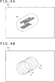
- FIGS. 4A to 4D are views illustrating estimation of a movement and an inverse filter based on an event signal in the embodiment of the present invention.
- an imaging target obj is captured in the RGB image 101. Since the imaging target obj moves during scanning by the image sensor 110, blurring occurs in the RGB image 101 and the picture of the imaging target obj is elongated as depicted in FIG. 4A .
- FIG. 4A On the other hand, as depicted in FIG.
- the event signal 201 indicates that an event has occurred with a pixel group P 1 immediately after the start of scanning of the RGB image 101, and the pixel group P 1 gradually moves (pixel groups P 2 , ..., P n-1 ) until an event occurs with the pixel group P n immediately before the end of the scanning.
- the movement estimation unit 310 estimates a movement region R and a movement vector V in the RGB image 101 as depicted in FIG. 4C .
- the movement region R is a region that includes the pixel groups P 1 , P 2 , ..., P n-1 , P n at which events have occurred during a period of time from the start to the end of the scanning (the region corresponds to the picture of the imaging target obj elongated as a result of occurrence of blur)
- the movement vector V is a vector for moving each pixel of the pixel group P 1 corresponding to the start point of the movement to each pixel of the pixel group P n corresponding to the end point of the movement.
- the movement estimation unit 310 need not refer to the RGB image 101 itself in order to estimate the movement region R and the movement vector V.
- the inverse filter generation unit 320 applies them to the RGB image 101 to generate an inverse filter 321 from which such an output image 331 as depicted in FIG. 4D is to be obtained.
- the inverse filter 321 acts in a limited way on pixels in the movement region R to cancel the movement vector V.
- the inverse filter 321 moves the pixels in the movement region R by a vector -kV obtained by multiplying an inverse vector -V of the movement vector V by a coefficient k.
- the coefficient k gradually increases such that, for example, it is 0 at the start point (pixel group P 1 ) of the movement vector V and becomes 1 at the end point (pixel group P n ).
- the enlarged picture of the imaging target obj is compressed to its original size and the influence of the blur caused by the movement of the imaging target obj is reduced.
- the movement estimation unit 310 of the image processing apparatus 300 estimates a movement of an imaging target in the RGB image 101 from the event signal 201. Since the event signal 201 is generated only in a case where an intensity change of light is detected at one or a plurality of pixels of the RGB image 101, the processing can be speeded up in comparison with that in an alternative case in which, for example, pixels of a plurality of RGB images 101 consecutive in time are compared with each other to estimate a movement.
- the inverse filter 321 generated by the inverse filter generation unit 320 acts in a limited way on the movement region R of the RGB image 101, occurrence of artifact can be suppressed, for example, in comparison with that in an alternative case in which a filter is applied to the overall RGB image 101 including a region other than the movement region R.
- the system 10 described in connection with the example described above may be incorporated in a single apparatus or may be distributed and implemented in a plurality of devices.
- the RGB image 101 acquired by the RGB camera 100 and the event signal 201 acquired by the EDS 200 may be stored into a memory together with the timestamps 102 and 202, and as post processing, estimation of a movement by the image processing apparatus 300, generation of an inverse filter 321, and application of the inverse filter 321 may be executed.
- the processes up to the generation of an inverse filter 321 by the image processing apparatus 300 may be executed, and the inverse filter 321 may be stored together with the RGB image 101.
- the inverse filter 321 may be applied to the RGB image 101, for example, in accordance with an operation of a user to generate an output image 331.
- an inverse filter 321 for compressing an elongated picture of an imaging target obj as a result of occurrence of blur to the start point side of the movement vector V is generated
- an inverse filter 321 that compresses a picture of the imaging target obj to the end side or to an intermediate point of the movement vector V may be generated.
- the inverse filter 321 to be generated on the basis of the event signal 201 is not limited to the example described above, and, for example, various filters each known as filter for reducing the influence of blur occurring by a movement of an imaging target can be used.
- the movement estimation unit 310 estimates the movement region R of the system 10 and the inverse filter generation unit 320 generates an inverse filter 321 that acts in a limited way upon the movement region R, occurrence of artifact can be suppressed, for example, in comparison with that in an alternative case in which a filter is applied to the overall RGB image 101.
- FIG. 5 is a flow chart depicting an example of an image processing method according to the embodiment of the present invention.
- the RGB camera 100 captures an RGB image 101 (step S101), and the EDS 200 simultaneously generates an event signal 201 (step S102).
- the step S102 at which the event signal 201 is generated is executed only in a case where the sensor 210 corresponding to one or a plurality of pixels of the RGB image 101 detects an intensity change of light.
- a timestamp 102 is provided to the RGB image 101 (step S103), and to the event signal, a timestamp 202 is provided (step S104).
- the movement estimation unit 310 estimates a movement of an imaging target in the RGB image 101 on the basis of the timestamp 102 of the RGB image 101, the event signal 201, and the timestamp 202 of the event signal 201 (step S105).
- the inverse filter generation unit 320 generates an inverse filter 321 on the basis of the estimated movement (step S106), and the filter application unit 330 applies the inverse filter 321 to the RGB image 101 (step S107).
- an output image 331 can be obtained in which the influence of blur appearing in the RGB image 101 by a movement of the imaging target is reduced.
Landscapes
- Engineering & Computer Science (AREA)
- Multimedia (AREA)
- Signal Processing (AREA)
- Physics & Mathematics (AREA)
- General Physics & Mathematics (AREA)
- Theoretical Computer Science (AREA)
- Computer Vision & Pattern Recognition (AREA)
- Human Computer Interaction (AREA)
- Computer Security & Cryptography (AREA)
- General Health & Medical Sciences (AREA)
- General Engineering & Computer Science (AREA)
- Biomedical Technology (AREA)
- Health & Medical Sciences (AREA)
- Image Analysis (AREA)
- Studio Devices (AREA)
- Image Processing (AREA)
Abstract
Description
- The present invention relates to an image processing apparatus, an imaging apparatus, a system, an image processing method, and a program.
- An event-driven type vision sensor is known in which pixels that detect an intensity change of incident light generate signals time-asynchronously. The event-driven type vision sensor is advantageous in that it can operate at a high speed with low power consumption in comparison with a frame type vision sensor in which all pixels are scanned in every predetermined cycle, particularly with CCD (Charge-Coupled Device) or CMOS (Complementary Metal-Oxide Semiconductor) image sensors and so forth. A technology related to such an event-driven type vision sensor as just described is disclosed, for example, in
PTL 1 and PTL 2. -
- [PTL 1]
JP 2014-535098T - [PTL 2]
JP 2018-85725A - However, regarding the event-driven type vision sensor, although such an advantage as described above is known, sufficient proposals have not been made for a utilization method of using the event-driven type vision sensor in combination with another device, for example, a frame type vision sensor.
- Therefore, it is an object of the present invention to provide an image processing apparatus, an imaging apparatus, a system, an image processing method, and a program that can achieve advantageous effects by using an event-driven type vision sensor in combination with a frame type vision sensor.
- According to a certain aspect of the present invention, there is provided an image processing apparatus including a movement estimation unit that estimates, on the basis of a first timestamp provided to an image captured by synchronous scanning, an event signal generated corresponding to an intensity change of light at one or a plurality of pixels of the image, and a second timestamp that is provided to the event signal and is in synchronism with the first timestamp, a movement of an imaging target in the image, an inverse filter generation unit that generates an inverse filter on the basis of the movement, and a filter application unit that applies the inverse filter to the image.
- According to another aspect of the present invention, there is provided an imaging apparatus including a first vision sensor that captures an image by synchronous scanning and provides a first timestamp to the image, and a second vision sensor that includes a sensor associated with one or a plurality of pixels of the image, generates, when the sensor detects an intensity change of light, an event signal, and provides a second timestamp synchronized with the first timestamp to the event signal.
- According to a further aspect of the present invention, there is provided a system including a first vision sensor that captures an image by synchronous scanning and provides a first timestamp to the image, a second vision sensor that includes a sensor associated with one or a plurality of pixels of the image, generates, when the sensor detects an intensity change of light, an event signal, and provides a second timestamp synchronized with the first timestamp to the event signal, and an image processing apparatus that includes a movement estimation unit that estimates a movement of an imaging target in the image on the basis of the first timestamp, the event signal, and the second timestamp, an inverse filter generation unit that generates an inverse filter on the basis of the movement, and a filter application unit that applies the inverse filter to the image.
- According to a still further aspect of the present invention, there is provided an image processing method including a step of capturing an image by synchronous scanning and providing a first timestamp to the image, a step of including a sensor associated with one or a plurality of pixels of the image, generating, when the sensor detects an intensity change of light, an event signal, and providing a second timestamp synchronized with the first timestamp to the event signal, a step of estimating a movement of an imaging target in the image on the basis of the first timestamp, the event signal, and the second timestamp, a step of generating an inverse filter on the basis of the movement, and a step of applying the inverse filter to the image.
- According to a yet further aspect of the present invention, there is provided a program for causing a computer to implement a function of estimating, on the basis of a first timestamp provided to an image captured by synchronous scanning, an event signal generated corresponding to an intensity change of light at one or a plurality of pixels of the image, and a second timestamp that is provided to the event signal and is in synchronism with the first timestamp, a movement of an imaging target in the image, a function of generating an inverse filter on the basis of the movement, and a function of applying the inverse filter to the image.
-
- [
FIG. 1 ]
FIG. 1 is a block diagram depicting a general configuration of a system according to an embodiment of the present invention. - [
FIG. 2 ]
FIG. 2 is a view schematically illustrating calibration between a camera and a sensor in the embodiment of the present invention. - [
FIG. 3 ]
FIG. 3 is a view illustrating an example of matching between an image and an event signal in the embodiment of the present invention. - [
FIG. 4A ]
FIG. 4A is a view illustrating estimation of a movement and an inverse filter based on an event signal in the embodiment of the present invention. - [
FIG. 4B ]
FIG. 4B is another view illustrating estimation of a movement and an inverse filter based on an event signal in the embodiment of the present invention. - [
FIG. 4C ]
FIG. 4C is a further view illustrating estimation of a movement and an inverse filter based on an event signal in the embodiment of the present invention. - [
FIG. 4D ]
FIG. 4D is a still further view illustrating estimation of a movement and an inverse filter based on an event signal in the embodiment of the present invention. - [
FIG. 5 ]
FIG. 5 is a flow chart depicting an example of an image processing method according to the embodiment of the present invention. - In the following, an embodiment of the present invention is described with reference to the accompanying drawings. It is to be noted that, in the present specification and the drawings, components having substantially same functional configurations are denoted by like reference signs and overlapping description of them is omitted herein.
-
FIG. 1 is a block diagram depicting a general configuration of a system according to an embodiment of the present invention. As depicted inFIG. 1 , asystem 10 includes an RGB (Red-Green-Blue)camera 100, an EDS (Event Driven Sensor) 200, and animage processing apparatus 300. - The
RGB camera 100 is an example of a first vision sensor that captures an image by synchronous scanning and includes animage sensor 110 and aprocessing circuit 120 connected to theimage sensor 110. Theimage sensor 110 captures anRGB image 101 by synchronously scanning all pixels, for example, in a predetermined cycle or at a predetermined timing according to a user operation. Theprocessing circuit 120 converts theRGB image 101 into a format, for example, suitable for storage or transmission. Further, theprocessing circuit 120 provides atimestamp 102 to theRGB image 101. For example, theprocessing circuit 120 provides atimestamp 102 indicative of at least any of start or end of scanning by theimage sensor 110 to theRGB image 101. For example, in the case of a still image, the period of time from the start to the end of scanning is referred to also as exposure period of time. - The EDS 200 is an example of a second vision sensor that generates an event signal when a sensor detects an intensity change of light and includes
sensors 210 configuring a sensor array and aprocessing circuit 220 connected to thesensors 210. Each of thesensors 210 includes a light reception element and generates anevent signal 201 when it detects an intensity change of light incident thereto, more particularly, a luminance change. Since anysensor 210 that does not detect an intensity change of incident light does not generate theevent signal 201, in the EDS 200, theevent signal 201 is generated time-asynchronously. Theevent signal 201 outputted through theprocessing circuit 220 includes identification information of the sensor 210 (for example, the position of a pixel), a polarity (increase or decrease) of a luminance change, and atimestamp 202. - Here, in the present embodiment, the
timestamp 102 provided to theRGB image 101 and thetimestamp 202 provided to theevent signal 201 are in synchronism with each other. In particular, thetimestamp 102 can be synchronized with thetimestamp 202, for example, by providing time information, which is used to generate thetimestamp 202 in theEDS 200, to theRGB camera 100. Alternatively, in a case where the time information for generating thetimestamps RGB camera 100 and theEDS 200, by calculating an offset amount between the timestamps with reference to time at which a specific event (for example, a change of an imaging target over an overall image) occurs, thetimestamp 102 and thetimestamp 202 can be synchronized with each other ex post facto. - Further, in the present embodiment, by a calibration procedure for the
RGB camera 100 and theEDS 200 executed in advance, eachsensor 210 of theEDS 200 is associated with one or a plurality of pixels of theRGB image 101, and theevent signal 201 is generated corresponding to an intensity change of light at one or a plurality of pixels of theRGB image 101. -
FIG. 2 is a view schematically illustrating calibration between a camera and a sensor in the embodiment of the present invention. In the example depicted, acalibration pattern 21 common to theRGB camera 100 and theEDS 200 is imaged (in the case of theEDS 200, by causing the overall region of thecalibration pattern 21 to flicker, for example, using alight source 22, the calibration pattern can be imaged), and corresponding parameters between the camera and the sensor are calculated from internal parameters and external parameters of theRGB camera 100 and theEDS 200. By this, eachsensor 210 can be associated with one or a plurality of pixels of theRGB image 101. For example, an imaging apparatus that includes a combination of theRGB camera 100 and theEDS 200 for which such synchronization of timestamps and a calibration procedure as described above are carried out in advance may be provided. -
FIG. 3 is a view illustrating an example of matching between an image and an event signal in the embodiment of the present invention. In the example depicted, anRGB image 101 captured by theRGB camera 100 and anevent signal 201 outputted from theEDS 200 at time corresponding to scanning of theRGB image 101 are depicted as arranged at positions of pixels. By calculating such corresponding parameters between the camera and the sensor as described hereinabove with reference toFIG. 2 in advance, it is possible to associate theevent signal 201 with one or a plurality of pixels of theRGB image 101 as depicted inFIG. 3 , in short, to superpose theevent signal 201 on theRGB image 101. - Referring again to
FIG. 1 , theimage processing apparatus 300 includes functions of amovement estimation unit 310, an inversefilter generation unit 320, and afilter application unit 330 that are incorporated by a computer including, for example, a communication interface, a processor, and a memory and are implemented by operation of the processor in accordance with a program stored in the memory or received through the communication interface. In the following, the functions of the components are described further. - The
movement estimation unit 310 estimates a movement of an imaging target in theRGB image 101 on the basis of thetimestamp 102 provided to theRGB image 101, theevent signal 201, and thetimestamp 202 provided to theevent signal 201. In a case where the imaging target of theRGB image 101 moves, an intensity change of light, particularly a luminance change, which appears at an edge portion of the imaging target, is detected from theevent signal 201. In other words, in the present embodiment, even if themovement estimation unit 310 does not refer to theRGB image 101 itself, it can estimate a movement of the imaging target in theRGB image 101 on the basis of theevent signal 201. Themovement estimation unit 310 can estimate, from a position change in time series of pixels with regard to which occurrence of a luminance change is indicated by theevent signal 201, a movement region in which the movement of the imaging target occurs in theRGB image 101 and a movement vector that indicates the movement of the imaging target in theRGB image 101. - In particular, for example, the
movement estimation unit 310 estimates a movement on the basis of the event signals 201 havingtimestamps 202 included within a period of time from the start to the end of scanning for capturing theRGB image 101. Here, the period of time from the start to the end of scanning is specified, for example, from two timestamps provided to theRGB image 101. Alternatively, even in a case where only a timestamp indicative of any of the start or the end of scanning is provided to theRGB image 101, if the duration of the scanning is known already, then the period of time from the start to the end of the scanning can be specified. As hereinafter described, for example, by applying an inverse filter generated on the basis of a movement of an imaging target occurring during a period of time from the start to the end of scanning, the influence of blur appearing in theRGB image 101 by a movement of an imaging target can be reduced. - The inverse
filter generation unit 320 generates an inverse filter 321 on the basis of a movement of an imaging target in theRGB image 101 estimated by themovement estimation unit 310. Here, the inverse filter is a filter that intends to bring theRGB image 101 closer to an original image of the imaging target by causing a change (filter) inverse to a change (filter) from an original picture of the imaging target caused in theRGB image 101 by a movement of the imaging target. Thefilter application unit 330 applies the inverse filter 321 to theRGB image 101 to obtain anoutput image 331. As hereinafter described, thefilter application unit 330 may apply a filter for compensating for a change caused in theRGB image 101 by application of the inverse filter 321 (for example, for filling up a blank region by enlarging the background) separately to theRGB image 101. -
FIGS. 4A to 4D are views illustrating estimation of a movement and an inverse filter based on an event signal in the embodiment of the present invention. In the examples depicted, an imaging target obj is captured in theRGB image 101. Since the imaging target obj moves during scanning by theimage sensor 110, blurring occurs in theRGB image 101 and the picture of the imaging target obj is elongated as depicted inFIG. 4A . On the other hand, as depicted inFIG. 4B , theevent signal 201 indicates that an event has occurred with a pixel group P1 immediately after the start of scanning of theRGB image 101, and the pixel group P1 gradually moves (pixel groups P2, ..., Pn-1) until an event occurs with the pixel group Pn immediately before the end of the scanning. - In this case, the
movement estimation unit 310 estimates a movement region R and a movement vector V in theRGB image 101 as depicted inFIG. 4C . For example, the movement region R is a region that includes the pixel groups P1, P2, ..., Pn-1, Pn at which events have occurred during a period of time from the start to the end of the scanning (the region corresponds to the picture of the imaging target obj elongated as a result of occurrence of blur), and the movement vector V is a vector for moving each pixel of the pixel group P1 corresponding to the start point of the movement to each pixel of the pixel group Pn corresponding to the end point of the movement. Since thesensor 210 for generating anevent signal 201 is associated with one or a plurality of pixels of theRGB image 101 as described hereinabove, themovement estimation unit 310 need not refer to theRGB image 101 itself in order to estimate the movement region R and the movement vector V. - In a case where such a movement region R and a movement vector V as described above are estimated, the inverse
filter generation unit 320 applies them to theRGB image 101 to generate an inverse filter 321 from which such anoutput image 331 as depicted inFIG. 4D is to be obtained. In the example depicted, the inverse filter 321 acts in a limited way on pixels in the movement region R to cancel the movement vector V. In particular, the inverse filter 321 moves the pixels in the movement region R by a vector -kV obtained by multiplying an inverse vector -V of the movement vector V by a coefficient k. The coefficient k gradually increases such that, for example, it is 0 at the start point (pixel group P1) of the movement vector V and becomes 1 at the end point (pixel group Pn). In theoutput image 331, the enlarged picture of the imaging target obj is compressed to its original size and the influence of the blur caused by the movement of the imaging target obj is reduced. - In such an embodiment of the present invention as described above, the
movement estimation unit 310 of theimage processing apparatus 300 estimates a movement of an imaging target in theRGB image 101 from theevent signal 201. Since theevent signal 201 is generated only in a case where an intensity change of light is detected at one or a plurality of pixels of theRGB image 101, the processing can be speeded up in comparison with that in an alternative case in which, for example, pixels of a plurality ofRGB images 101 consecutive in time are compared with each other to estimate a movement. Further, since the inverse filter 321 generated by the inversefilter generation unit 320 acts in a limited way on the movement region R of theRGB image 101, occurrence of artifact can be suppressed, for example, in comparison with that in an alternative case in which a filter is applied to theoverall RGB image 101 including a region other than the movement region R. - It is to be noted that the
system 10 described in connection with the example described above may be incorporated in a single apparatus or may be distributed and implemented in a plurality of devices. For example, theRGB image 101 acquired by theRGB camera 100 and theevent signal 201 acquired by theEDS 200 may be stored into a memory together with thetimestamps image processing apparatus 300, generation of an inverse filter 321, and application of the inverse filter 321 may be executed. Alternatively, when theRGB image 101 and theevent signal 201 are acquired, the processes up to the generation of an inverse filter 321 by theimage processing apparatus 300 may be executed, and the inverse filter 321 may be stored together with theRGB image 101. In this case, when theRGB image 101 is displayed, the inverse filter 321 may be applied to theRGB image 101, for example, in accordance with an operation of a user to generate anoutput image 331. - Further, although, in the example depicted in
FIG. 4D , an inverse filter 321 for compressing an elongated picture of an imaging target obj as a result of occurrence of blur to the start point side of the movement vector V is generated, in another example, an inverse filter 321 that compresses a picture of the imaging target obj to the end side or to an intermediate point of the movement vector V may be generated. Further, the inverse filter 321 to be generated on the basis of theevent signal 201 is not limited to the example described above, and, for example, various filters each known as filter for reducing the influence of blur occurring by a movement of an imaging target can be used. Also in those cases, for example, if themovement estimation unit 310 estimates the movement region R of thesystem 10 and the inversefilter generation unit 320 generates an inverse filter 321 that acts in a limited way upon the movement region R, occurrence of artifact can be suppressed, for example, in comparison with that in an alternative case in which a filter is applied to theoverall RGB image 101. -
FIG. 5 is a flow chart depicting an example of an image processing method according to the embodiment of the present invention. In the example depicted, theRGB camera 100 captures an RGB image 101 (step S101), and theEDS 200 simultaneously generates an event signal 201 (step S102). It is to be noted that the step S102 at which theevent signal 201 is generated is executed only in a case where thesensor 210 corresponding to one or a plurality of pixels of theRGB image 101 detects an intensity change of light. Atimestamp 102 is provided to the RGB image 101 (step S103), and to the event signal, atimestamp 202 is provided (step S104). - Then, processing by the
image processing apparatus 300 is executed. First, themovement estimation unit 310 estimates a movement of an imaging target in theRGB image 101 on the basis of thetimestamp 102 of theRGB image 101, theevent signal 201, and thetimestamp 202 of the event signal 201 (step S105). Then, the inversefilter generation unit 320 generates an inverse filter 321 on the basis of the estimated movement (step S106), and thefilter application unit 330 applies the inverse filter 321 to the RGB image 101 (step S107). By such processes as described above, for example, anoutput image 331 can be obtained in which the influence of blur appearing in theRGB image 101 by a movement of the imaging target is reduced. - Although an embodiment of the present invention has been described in detail with reference to the accompanying drawings, the present invention is not limited to such an embodiment. It is apparent that persons who have common knowledge in the technical field to which the present invention pertains could have conceived various alterations or modifications within the scope of the technical idea described in the claims, and it is construed that also they naturally fall within the technical scope of the present invention.
-
- 10:
- System
- 100:
- RGB camera
- 101:
- RGB image
- 102:
- Timestamp
- 110:
- Image sensor
- 120:
- Processing circuit
- 201:
- Event signal
- 202:
- Timestamp
- 210:
- Sensor
- 220:
- Processing circuit
- 300:
- Image processing apparatus
- 310:
- Movement estimation unit
- 320:
- Inverse filter generation unit
- 321:
- Inverse filter
- 330:
- Filter application unit
- 331:
- Output image
Claims (8)
- An image processing apparatus comprising:a movement estimation unit that estimates, on a basis of a first timestamp provided to an image captured by synchronous scanning, an event signal generated corresponding to an intensity change of light at one or a plurality of pixels of the image, and a second timestamp that is provided to the event signal and is in synchronism with the first timestamp, a movement of an imaging target in the image;an inverse filter generation unit that generates an inverse filter on a basis of the movement; anda filter application unit that applies the inverse filter to the image.
- The image processing apparatus according to claim 1, whereinthe first timestamp includes a timestamp indicative of at least any of start or end of the scanning, andthe movement estimation unit estimates a movement of the imaging target in the image on a basis of the event signal having the second timestamp included in a period of time from the start to the end of the scanning.
- The image processing apparatus according to claim 1 or 2, whereinthe movement estimation unit estimates a movement region in which a movement of the imaging target has occurred in the image, andthe inverse filter generation unit generates the inverse filter that acts in a limited way on the movement region.
- The image processing apparatus according to any one of claims 1 to 3, whereinthe movement estimation unit estimates a movement vector indicative of a movement of the imaging target in the image, andthe inverse filter generation unit generates the inverse filter that cancels the movement vector.
- An imaging apparatus comprising:a first vision sensor that captures an image by synchronous scanning and provides a first timestamp to the image; anda second vision sensor that includes a sensor associated with one or a plurality of pixels of the image, generates, when the sensor detects an intensity change of light, an event signal,and provides a second timestamp synchronized with the first timestamp to the event signal.
- A system comprising:a first vision sensor that captures an image by synchronous scanning and provides a first timestamp to the image;a second vision sensor that includes a sensor associated with one or a plurality of pixels of the image, generates, when the sensor detects an intensity change of light, an event signal,and provides a second timestamp synchronized with the first timestamp to the event signal; andan image processing apparatus that includesa movement estimation unit that estimates a movement of an imaging target in the image on a basis of the first timestamp, the event signal, and the second timestamp,an inverse filter generation unit that generates an inverse filter on a basis of the movement, anda filter application unit that applies the inverse filter to the image.
- An image processing method comprising:a step of capturing an image by synchronous scanning andproviding a first timestamp to the image;a step of including a sensor associated with one or a plurality of pixels of the image, generating, when the sensor detects an intensity change of light, an event signal, and providing a second timestamp synchronized with the first timestamp to the event signal;a step of estimating a movement of an imaging target in the image on a basis of the first timestamp, the event signal, andthe second timestamp;a step of generating an inverse filter on a basis of the movement; anda step of applying the inverse filter to the image.
- A program for causing a computer to implement:a function of estimating, on a basis of a first timestamp provided to an image captured by synchronous scanning, an event signal generated corresponding to an intensity change of light at one or a plurality of pixels of the image, and a second timestamp that is provided to the event signal and is in synchronism with the first timestamp, a movement of an imaging target in the image;a function of generating an inverse filter on a basis of the movement; anda function of applying the inverse filter to the image.
Applications Claiming Priority (1)
| Application Number | Priority Date | Filing Date | Title |
|---|---|---|---|
| PCT/JP2019/032342 WO2021033250A1 (en) | 2019-08-20 | 2019-08-20 | Image processing device, image capture device, system, image processing method, and program |
Publications (3)
| Publication Number | Publication Date |
|---|---|
| EP4020962A1 true EP4020962A1 (en) | 2022-06-29 |
| EP4020962A4 EP4020962A4 (en) | 2023-05-10 |
| EP4020962B1 EP4020962B1 (en) | 2025-04-23 |
Family
ID=74660624
Family Applications (1)
| Application Number | Title | Priority Date | Filing Date |
|---|---|---|---|
| EP19942090.2A Active EP4020962B1 (en) | 2019-08-20 | 2019-08-20 | Image processing device, image capture device, system, image processing method, and program |
Country Status (6)
| Country | Link |
|---|---|
| US (1) | US11954866B2 (en) |
| EP (1) | EP4020962B1 (en) |
| JP (1) | JP7197715B2 (en) |
| KR (1) | KR102916853B1 (en) |
| CN (1) | CN114245983B (en) |
| WO (1) | WO2021033250A1 (en) |
Families Citing this family (6)
| Publication number | Priority date | Publication date | Assignee | Title |
|---|---|---|---|---|
| EP3929864A1 (en) * | 2020-06-23 | 2021-12-29 | Prophesee | Image enhancement method, apparatus and system |
| JP7851119B2 (en) * | 2021-12-24 | 2026-04-24 | キヤノン株式会社 | Imaging device, its control method, and program |
| KR20240126282A (en) | 2023-02-13 | 2024-08-20 | 삼성전자주식회사 | Vision sensor, its and image processing device including the same |
| WO2024194944A1 (en) * | 2023-03-17 | 2024-09-26 | 株式会社ソニー・インタラクティブエンタテインメント | Information processing device, system, information processing method, information processing program, and computer system |
| CN121195515A (en) * | 2023-05-23 | 2025-12-23 | Oppo广东移动通信有限公司 | Image processing equipment, image processing methods and programs |
| US20250159375A1 (en) * | 2023-11-09 | 2025-05-15 | Omnivision Technologies, Inc. | Hybrid image sensors with adjustable contrast thresholds |
Family Cites Families (14)
| Publication number | Priority date | Publication date | Assignee | Title |
|---|---|---|---|---|
| JP2003209735A (en) * | 2002-01-15 | 2003-07-25 | Hitachi Ltd | Monitoring device and storage camera with blur correction function |
| KR101880998B1 (en) | 2011-10-14 | 2018-07-24 | 삼성전자주식회사 | Apparatus and Method for motion recognition with event base vision sensor |
| US9986179B2 (en) * | 2014-09-30 | 2018-05-29 | Qualcomm Incorporated | Sensor architecture using frame-based and event-based hybrid scheme |
| US9549100B2 (en) * | 2015-04-23 | 2017-01-17 | Microsoft Technology Licensing, Llc | Low-latency timing control |
| WO2017049589A1 (en) * | 2015-09-25 | 2017-03-30 | Qualcomm Incorporated | Systems and methods for video processing |
| US10062151B2 (en) * | 2016-01-21 | 2018-08-28 | Samsung Electronics Co., Ltd. | Image deblurring method and apparatus |
| US10434624B2 (en) | 2016-07-07 | 2019-10-08 | The Boeing Company | Roto peening orbital drilling tool |
| US10110913B2 (en) * | 2016-09-30 | 2018-10-23 | Intel Corporation | Motion estimation using hybrid video imaging system |
| US20180146149A1 (en) | 2016-11-21 | 2018-05-24 | Samsung Electronics Co., Ltd. | Event-based sensor, user device including the same, and operation method of the same |
| JP7027737B2 (en) | 2017-09-05 | 2022-03-02 | ソニーグループ株式会社 | Image processing equipment, image processing method, and program |
| CN108074222A (en) * | 2017-12-25 | 2018-05-25 | 清华大学 | High-speed moving object deblurring method and device based on Hybrid camera system |
| CN108989606B (en) * | 2018-08-22 | 2021-02-09 | Oppo广东移动通信有限公司 | Image processing method and device, electronic equipment and computer readable storage medium |
| US12142025B2 (en) * | 2021-11-16 | 2024-11-12 | Intrinsic Innovation Llc | Polarization event cameras |
| US20230169665A1 (en) * | 2021-12-01 | 2023-06-01 | Intrinsic Innovation Llc | Systems and methods for temporal autocalibration in a camera system |
-
2019
- 2019-08-20 KR KR1020227003456A patent/KR102916853B1/en active Active
- 2019-08-20 CN CN201980099252.5A patent/CN114245983B/en active Active
- 2019-08-20 US US17/634,300 patent/US11954866B2/en active Active
- 2019-08-20 WO PCT/JP2019/032342 patent/WO2021033250A1/en not_active Ceased
- 2019-08-20 JP JP2021541371A patent/JP7197715B2/en active Active
- 2019-08-20 EP EP19942090.2A patent/EP4020962B1/en active Active
Also Published As
| Publication number | Publication date |
|---|---|
| EP4020962B1 (en) | 2025-04-23 |
| CN114245983B (en) | 2024-03-22 |
| US11954866B2 (en) | 2024-04-09 |
| WO2021033250A1 (en) | 2021-02-25 |
| JPWO2021033250A1 (en) | 2021-02-25 |
| KR20220050130A (en) | 2022-04-22 |
| JP7197715B2 (en) | 2022-12-27 |
| US20220284593A1 (en) | 2022-09-08 |
| CN114245983A (en) | 2022-03-25 |
| KR102916853B1 (en) | 2026-01-23 |
| EP4020962A4 (en) | 2023-05-10 |
Similar Documents
| Publication | Publication Date | Title |
|---|---|---|
| US11954866B2 (en) | Image processing apparatus using movement estimation, imaging apparatus, system, image processing method, and program | |
| CN103201766B (en) | Method for producing high dynamic range images | |
| US10225468B2 (en) | Imaging systems and methods with image data path delay measurement | |
| EP2323376B1 (en) | Image sensor with shaking compensation | |
| CN102223484A (en) | Method and device for configuring head-end parameter of camera | |
| US12348889B2 (en) | Image processing apparatus, method of controlling image processing apparatus, and program storage | |
| CN102572245A (en) | Method and device for extending image dynamic ranges | |
| KR20180121879A (en) | An image pickup control device, and an image pickup control method, | |
| JP4250583B2 (en) | Image capturing apparatus and image restoration method | |
| JP5581968B2 (en) | Imaging device | |
| US8643752B1 (en) | System and method for reducing motion blur using CCD charge shifting | |
| US10313619B2 (en) | Photographing apparatus including an oscillator outputting an output signal based on which a first timing signal and a second timing signal are generated | |
| JP2007104349A (en) | Imaging device | |
| CN107211098A (en) | For the control of the time for exposure based on noise level of sequential sub-images | |
| JPWO2020116213A1 (en) | Receiver and transmitter | |
| US11910110B2 (en) | Transfer control device, image processing device, transfer control method, and program | |
| KR101610512B1 (en) | Stereoscopic camera and method for operating the same | |
| JP2021005798A (en) | Imaging apparatus, control method of imaging apparatus, and program | |
| US11792527B2 (en) | Sensor system, image processing apparatus, image processing method, and program | |
| JP5482475B2 (en) | Image processing apparatus, display apparatus, and photographing apparatus | |
| JP3961975B2 (en) | Signal processing apparatus and digital camera | |
| US20210203899A1 (en) | Image processing device, image processing method, and imaging device | |
| KR20190140237A (en) | Method and Apparatus for Generating Stereo Image | |
| US10778893B2 (en) | Detection device, display device and detection method | |
| JP2000152080A (en) | Virtual space synthesis method and apparatus |
Legal Events
| Date | Code | Title | Description |
|---|---|---|---|
| STAA | Information on the status of an ep patent application or granted ep patent |
Free format text: STATUS: THE INTERNATIONAL PUBLICATION HAS BEEN MADE |
|
| PUAI | Public reference made under article 153(3) epc to a published international application that has entered the european phase |
Free format text: ORIGINAL CODE: 0009012 |
|
| STAA | Information on the status of an ep patent application or granted ep patent |
Free format text: STATUS: REQUEST FOR EXAMINATION WAS MADE |
|
| 17P | Request for examination filed |
Effective date: 20220130 |
|
| AK | Designated contracting states |
Kind code of ref document: A1 Designated state(s): AL AT BE BG CH CY CZ DE DK EE ES FI FR GB GR HR HU IE IS IT LI LT LU LV MC MK MT NL NO PL PT RO RS SE SI SK SM TR |
|
| DAV | Request for validation of the european patent (deleted) | ||
| DAX | Request for extension of the european patent (deleted) | ||
| REG | Reference to a national code |
Ref country code: DE Ref legal event code: R079 Free format text: PREVIOUS MAIN CLASS: H04N0005232000 Ipc: H04N0023450000 Ref country code: DE Ref legal event code: R079 Ref document number: 602019069199 Country of ref document: DE Free format text: PREVIOUS MAIN CLASS: H04N0005232000 Ipc: H04N0023450000 |
|
| A4 | Supplementary search report drawn up and despatched |
Effective date: 20230406 |
|
| RIC1 | Information provided on ipc code assigned before grant |
Ipc: G06T 5/50 20060101ALI20230331BHEP Ipc: H04N 17/00 20060101ALI20230331BHEP Ipc: H04N 5/77 20060101ALI20230331BHEP Ipc: H04N 5/14 20060101ALI20230331BHEP Ipc: H04N 1/32 20060101ALI20230331BHEP Ipc: H04N 1/00 20060101ALI20230331BHEP Ipc: G06T 5/20 20060101ALI20230331BHEP Ipc: H04N 25/707 20230101ALI20230331BHEP Ipc: H04N 25/47 20230101ALI20230331BHEP Ipc: G06T 7/20 20170101ALI20230331BHEP Ipc: G06T 5/00 20060101ALI20230331BHEP Ipc: H04N 23/90 20230101ALI20230331BHEP Ipc: H04N 23/71 20230101ALI20230331BHEP Ipc: H04N 23/68 20230101ALI20230331BHEP Ipc: H04N 23/45 20230101AFI20230331BHEP |
|
| GRAP | Despatch of communication of intention to grant a patent |
Free format text: ORIGINAL CODE: EPIDOSNIGR1 |
|
| STAA | Information on the status of an ep patent application or granted ep patent |
Free format text: STATUS: GRANT OF PATENT IS INTENDED |
|
| RIC1 | Information provided on ipc code assigned before grant |
Ipc: G06T 5/73 20240101ALI20241108BHEP Ipc: G06T 5/50 20060101ALI20241108BHEP Ipc: H04N 17/00 20060101ALI20241108BHEP Ipc: H04N 5/77 20060101ALI20241108BHEP Ipc: H04N 5/14 20060101ALI20241108BHEP Ipc: H04N 1/32 20060101ALI20241108BHEP Ipc: H04N 1/00 20060101ALI20241108BHEP Ipc: G06T 5/20 20060101ALI20241108BHEP Ipc: H04N 25/707 20230101ALI20241108BHEP Ipc: H04N 25/47 20230101ALI20241108BHEP Ipc: G06T 7/20 20170101ALI20241108BHEP Ipc: G06T 5/00 20060101ALI20241108BHEP Ipc: H04N 23/90 20230101ALI20241108BHEP Ipc: H04N 23/71 20230101ALI20241108BHEP Ipc: H04N 23/68 20230101ALI20241108BHEP Ipc: H04N 23/45 20230101AFI20241108BHEP |
|
| INTG | Intention to grant announced |
Effective date: 20241127 |
|
| GRAS | Grant fee paid |
Free format text: ORIGINAL CODE: EPIDOSNIGR3 |
|
| GRAA | (expected) grant |
Free format text: ORIGINAL CODE: 0009210 |
|
| STAA | Information on the status of an ep patent application or granted ep patent |
Free format text: STATUS: THE PATENT HAS BEEN GRANTED |
|
| P01 | Opt-out of the competence of the unified patent court (upc) registered |
Free format text: CASE NUMBER: APP_9536/2025 Effective date: 20250226 |
|
| AK | Designated contracting states |
Kind code of ref document: B1 Designated state(s): AL AT BE BG CH CY CZ DE DK EE ES FI FR GB GR HR HU IE IS IT LI LT LU LV MC MK MT NL NO PL PT RO RS SE SI SK SM TR |
|
| REG | Reference to a national code |
Ref country code: GB Ref legal event code: FG4D |
|
| REG | Reference to a national code |
Ref country code: CH Ref legal event code: EP |
|
| REG | Reference to a national code |
Ref country code: DE Ref legal event code: R096 Ref document number: 602019069199 Country of ref document: DE |
|
| REG | Reference to a national code |
Ref country code: IE Ref legal event code: FG4D |
|
| REG | Reference to a national code |
Ref country code: NL Ref legal event code: FP |
|
| PGFP | Annual fee paid to national office [announced via postgrant information from national office to epo] |
Ref country code: NL Payment date: 20250723 Year of fee payment: 7 |
|
| REG | Reference to a national code |
Ref country code: AT Ref legal event code: MK05 Ref document number: 1788972 Country of ref document: AT Kind code of ref document: T Effective date: 20250423 |
|
| PG25 | Lapsed in a contracting state [announced via postgrant information from national office to epo] |
Ref country code: ES Free format text: LAPSE BECAUSE OF FAILURE TO SUBMIT A TRANSLATION OF THE DESCRIPTION OR TO PAY THE FEE WITHIN THE PRESCRIBED TIME-LIMIT Effective date: 20250423 Ref country code: PT Free format text: LAPSE BECAUSE OF FAILURE TO SUBMIT A TRANSLATION OF THE DESCRIPTION OR TO PAY THE FEE WITHIN THE PRESCRIBED TIME-LIMIT Effective date: 20250825 Ref country code: FI Free format text: LAPSE BECAUSE OF FAILURE TO SUBMIT A TRANSLATION OF THE DESCRIPTION OR TO PAY THE FEE WITHIN THE PRESCRIBED TIME-LIMIT Effective date: 20250423 |
|
| PGFP | Annual fee paid to national office [announced via postgrant information from national office to epo] |
Ref country code: DE Payment date: 20250724 Year of fee payment: 7 |
|
| REG | Reference to a national code |
Ref country code: LT Ref legal event code: MG9D |
|
| PG25 | Lapsed in a contracting state [announced via postgrant information from national office to epo] |
Ref country code: NO Free format text: LAPSE BECAUSE OF FAILURE TO SUBMIT A TRANSLATION OF THE DESCRIPTION OR TO PAY THE FEE WITHIN THE PRESCRIBED TIME-LIMIT Effective date: 20250723 Ref country code: GR Free format text: LAPSE BECAUSE OF FAILURE TO SUBMIT A TRANSLATION OF THE DESCRIPTION OR TO PAY THE FEE WITHIN THE PRESCRIBED TIME-LIMIT Effective date: 20250724 |
|
| PG25 | Lapsed in a contracting state [announced via postgrant information from national office to epo] |
Ref country code: PL Free format text: LAPSE BECAUSE OF FAILURE TO SUBMIT A TRANSLATION OF THE DESCRIPTION OR TO PAY THE FEE WITHIN THE PRESCRIBED TIME-LIMIT Effective date: 20250423 |
|
| PG25 | Lapsed in a contracting state [announced via postgrant information from national office to epo] |
Ref country code: BG Free format text: LAPSE BECAUSE OF FAILURE TO SUBMIT A TRANSLATION OF THE DESCRIPTION OR TO PAY THE FEE WITHIN THE PRESCRIBED TIME-LIMIT Effective date: 20250423 |
|
| PGFP | Annual fee paid to national office [announced via postgrant information from national office to epo] |
Ref country code: GB Payment date: 20250725 Year of fee payment: 7 |
|
| PG25 | Lapsed in a contracting state [announced via postgrant information from national office to epo] |
Ref country code: HR Free format text: LAPSE BECAUSE OF FAILURE TO SUBMIT A TRANSLATION OF THE DESCRIPTION OR TO PAY THE FEE WITHIN THE PRESCRIBED TIME-LIMIT Effective date: 20250423 |
|
| PG25 | Lapsed in a contracting state [announced via postgrant information from national office to epo] |
Ref country code: AT Free format text: LAPSE BECAUSE OF FAILURE TO SUBMIT A TRANSLATION OF THE DESCRIPTION OR TO PAY THE FEE WITHIN THE PRESCRIBED TIME-LIMIT Effective date: 20250423 |
|
| PGFP | Annual fee paid to national office [announced via postgrant information from national office to epo] |
Ref country code: FR Payment date: 20250723 Year of fee payment: 7 |
|
| PG25 | Lapsed in a contracting state [announced via postgrant information from national office to epo] |
Ref country code: RS Free format text: LAPSE BECAUSE OF FAILURE TO SUBMIT A TRANSLATION OF THE DESCRIPTION OR TO PAY THE FEE WITHIN THE PRESCRIBED TIME-LIMIT Effective date: 20250723 |
|
| PG25 | Lapsed in a contracting state [announced via postgrant information from national office to epo] |
Ref country code: IS Free format text: LAPSE BECAUSE OF FAILURE TO SUBMIT A TRANSLATION OF THE DESCRIPTION OR TO PAY THE FEE WITHIN THE PRESCRIBED TIME-LIMIT Effective date: 20250823 |
|
| PG25 | Lapsed in a contracting state [announced via postgrant information from national office to epo] |
Ref country code: LV Free format text: LAPSE BECAUSE OF FAILURE TO SUBMIT A TRANSLATION OF THE DESCRIPTION OR TO PAY THE FEE WITHIN THE PRESCRIBED TIME-LIMIT Effective date: 20250423 |
|
| PG25 | Lapsed in a contracting state [announced via postgrant information from national office to epo] |
Ref country code: DK Free format text: LAPSE BECAUSE OF FAILURE TO SUBMIT A TRANSLATION OF THE DESCRIPTION OR TO PAY THE FEE WITHIN THE PRESCRIBED TIME-LIMIT Effective date: 20250423 Ref country code: SM Free format text: LAPSE BECAUSE OF FAILURE TO SUBMIT A TRANSLATION OF THE DESCRIPTION OR TO PAY THE FEE WITHIN THE PRESCRIBED TIME-LIMIT Effective date: 20250423 |
|
| PG25 | Lapsed in a contracting state [announced via postgrant information from national office to epo] |
Ref country code: CZ Free format text: LAPSE BECAUSE OF FAILURE TO SUBMIT A TRANSLATION OF THE DESCRIPTION OR TO PAY THE FEE WITHIN THE PRESCRIBED TIME-LIMIT Effective date: 20250423 |
|
| PG25 | Lapsed in a contracting state [announced via postgrant information from national office to epo] |
Ref country code: EE Free format text: LAPSE BECAUSE OF FAILURE TO SUBMIT A TRANSLATION OF THE DESCRIPTION OR TO PAY THE FEE WITHIN THE PRESCRIBED TIME-LIMIT Effective date: 20250423 |
|
| REG | Reference to a national code |
Ref country code: DE Ref legal event code: R097 Ref document number: 602019069199 Country of ref document: DE |
|
| PG25 | Lapsed in a contracting state [announced via postgrant information from national office to epo] |
Ref country code: SK Free format text: LAPSE BECAUSE OF FAILURE TO SUBMIT A TRANSLATION OF THE DESCRIPTION OR TO PAY THE FEE WITHIN THE PRESCRIBED TIME-LIMIT Effective date: 20250423 Ref country code: RO Free format text: LAPSE BECAUSE OF FAILURE TO SUBMIT A TRANSLATION OF THE DESCRIPTION OR TO PAY THE FEE WITHIN THE PRESCRIBED TIME-LIMIT Effective date: 20250423 |
|
| PG25 | Lapsed in a contracting state [announced via postgrant information from national office to epo] |
Ref country code: IT Free format text: LAPSE BECAUSE OF FAILURE TO SUBMIT A TRANSLATION OF THE DESCRIPTION OR TO PAY THE FEE WITHIN THE PRESCRIBED TIME-LIMIT Effective date: 20250423 |
|
| PLBE | No opposition filed within time limit |
Free format text: ORIGINAL CODE: 0009261 |
|
| STAA | Information on the status of an ep patent application or granted ep patent |
Free format text: STATUS: NO OPPOSITION FILED WITHIN TIME LIMIT |
|
| REG | Reference to a national code |
Ref country code: CH Ref legal event code: L10 Free format text: ST27 STATUS EVENT CODE: U-0-0-L10-L00 (AS PROVIDED BY THE NATIONAL OFFICE) Effective date: 20260304 |
|
| REG | Reference to a national code |
Ref country code: CH Ref legal event code: H13 Free format text: ST27 STATUS EVENT CODE: U-0-0-H10-H13 (AS PROVIDED BY THE NATIONAL OFFICE) Effective date: 20260324 |
|
| PG25 | Lapsed in a contracting state [announced via postgrant information from national office to epo] |
Ref country code: MC Free format text: LAPSE BECAUSE OF FAILURE TO SUBMIT A TRANSLATION OF THE DESCRIPTION OR TO PAY THE FEE WITHIN THE PRESCRIBED TIME-LIMIT Effective date: 20250423 |
|
| 26N | No opposition filed |
Effective date: 20260126 |
|
| PG25 | Lapsed in a contracting state [announced via postgrant information from national office to epo] |
Ref country code: LU Free format text: LAPSE BECAUSE OF NON-PAYMENT OF DUE FEES Effective date: 20250820 |
|
| PG25 | Lapsed in a contracting state [announced via postgrant information from national office to epo] |
Ref country code: CH Free format text: LAPSE BECAUSE OF NON-PAYMENT OF DUE FEES Effective date: 20250831 |